EP0682395A2 - Dispositif pour limitation de la vitesse de changement des courants et tensions entre conducteurs ou vers la terre et procédé l'utilisant - Google Patents
Dispositif pour limitation de la vitesse de changement des courants et tensions entre conducteurs ou vers la terre et procédé l'utilisant Download PDFInfo
- Publication number
- EP0682395A2 EP0682395A2 EP95106490A EP95106490A EP0682395A2 EP 0682395 A2 EP0682395 A2 EP 0682395A2 EP 95106490 A EP95106490 A EP 95106490A EP 95106490 A EP95106490 A EP 95106490A EP 0682395 A2 EP0682395 A2 EP 0682395A2
- Authority
- EP
- European Patent Office
- Prior art keywords
- windings
- core
- currents
- voltages
- common component
- Prior art date
- Legal status (The legal status is an assumption and is not a legal conclusion. Google has not performed a legal analysis and makes no representation as to the accuracy of the status listed.)
- Granted
Links
Images

Classifications
-
- H—ELECTRICITY
- H02—GENERATION; CONVERSION OR DISTRIBUTION OF ELECTRIC POWER
- H02H—EMERGENCY PROTECTIVE CIRCUIT ARRANGEMENTS
- H02H9/00—Emergency protective circuit arrangements for limiting excess current or voltage without disconnection
- H02H9/005—Emergency protective circuit arrangements for limiting excess current or voltage without disconnection avoiding undesired transient conditions
-
- H—ELECTRICITY
- H01—ELECTRIC ELEMENTS
- H01F—MAGNETS; INDUCTANCES; TRANSFORMERS; SELECTION OF MATERIALS FOR THEIR MAGNETIC PROPERTIES
- H01F37/00—Fixed inductances not covered by group H01F17/00
-
- H—ELECTRICITY
- H02—GENERATION; CONVERSION OR DISTRIBUTION OF ELECTRIC POWER
- H02H—EMERGENCY PROTECTIVE CIRCUIT ARRANGEMENTS
- H02H7/00—Emergency protective circuit arrangements specially adapted for specific types of electric machines or apparatus or for sectionalised protection of cable or line systems, and effecting automatic switching in the event of an undesired change from normal working conditions
- H02H7/10—Emergency protective circuit arrangements specially adapted for specific types of electric machines or apparatus or for sectionalised protection of cable or line systems, and effecting automatic switching in the event of an undesired change from normal working conditions for converters; for rectifiers
- H02H7/12—Emergency protective circuit arrangements specially adapted for specific types of electric machines or apparatus or for sectionalised protection of cable or line systems, and effecting automatic switching in the event of an undesired change from normal working conditions for converters; for rectifiers for static converters or rectifiers
- H02H7/122—Emergency protective circuit arrangements specially adapted for specific types of electric machines or apparatus or for sectionalised protection of cable or line systems, and effecting automatic switching in the event of an undesired change from normal working conditions for converters; for rectifiers for static converters or rectifiers for inverters, i.e. dc/ac converters
- H02H7/1227—Emergency protective circuit arrangements specially adapted for specific types of electric machines or apparatus or for sectionalised protection of cable or line systems, and effecting automatic switching in the event of an undesired change from normal working conditions for converters; for rectifiers for static converters or rectifiers for inverters, i.e. dc/ac converters responsive to abnormalities in the output circuit, e.g. short circuit
Definitions
- the present invention is in the field of power electronics for drive technology, in particular in the field of converters and line filters for electromagnetic compatibility.
- the invention relates to a device for limiting the rate of change of currents and voltages between the live lines and relative to the ground potential for converters in drive technology or as a line filter for electromagnetic compatibility, with a capacitance and inductance LC low pass.
- the low-pass filter contains so-called current rise limiting chokes as inductors, to which branches with two diodes each are connected.
- This known device acts on the so-called symmetrical voltages, which are the voltages between the live lines, and can therefore significantly reduce the stress on the insulation of the induction machines connected to the converter due to steep voltage pulses and also the stress on the power semiconductors due to the connecting cables.
- the invention is now to provide a device of the type mentioned, which acts on both symmetrical and asymmetrical interference voltages, and which consists of as few components as possible and is therefore easy and inexpensive to manufacture and assemble.
- the solution to this problem according to the invention is characterized in that all inductors are combined to form a common component, and that this component is designed such that it corresponds functionally to a series connection of a current-compensated choke with several chokes acting as a series inductor.
- This common component is simple and inexpensive to manufacture and assemble, and it acts on symmetrical and asymmetrical interference voltages.
- it is very saturation-proof and therefore particularly suitable for higher asymmetrical currents.
- the invention further relates to a use of the device mentioned for converters in drive technology, which output terminals for the connection of at least have a three-phase machine.
- This use is characterized in that the said common component is inserted between the output terminals of the converter and the connecting line to the at least one induction machine.
- the invention further relates to a use of the device mentioned as a line filter for electromagnetic compatibility for an electronic device.
- This use is characterized in that the said common component is inserted between the network and the network input of the electronic device.
- induction machine or induction machines both a single machine as well as a group of several machines, in particular a single motor or an ensemble of motors.
- FETs or IGBTs are used as power semiconductor switches, for example, which work very quickly and with very steep rising edges of the pulses. This means that the losses in converter 1 are kept as low as possible, so that it is possible to work with a very high degree of efficiency, but the following problems arise: Inadmissibly high stress on the insulation of the connected induction machines due to very steep voltage pulses and overvoltages with longer connection cables, impermissible Functional impairment of neighboring assemblies or of cables routed parallel to the connecting cable between the converter and lathes as well as impermissible stress on the power semiconductors in the converter due to the cables connected to the output of the induction machines.
- Some of these problems namely those that are related to the (symmetrical) voltages between live lines, that is the stress on the insulation of the induction machines due to steep voltage pulses and the stress on the power semiconductors due to the connecting cables, are solved by inserting a lossy LC Low pass filters with inductors L, capacitors C and resistors R in the connecting cable between the output terminals 3 of the converter 1 and the induction machines 4 have been eliminated.
- the capacitances C can be switched both in the Y and in the ⁇ shape.
- Current-compensated chokes are designed so that with normal operating current (motor current) the magnetic fluxes generated in the core cancel each other out and the inductances are practically ineffective. However, if unbalanced currents flow from ground potential or back to DC link 2, the sum of the total currents is unequal and the magnetic fluxes no longer cancel each other out.
- a particular advantage of these current-compensated chokes is that high inductance values can be achieved with a relatively small construction volume, the size of the inductance naturally having to be designed for the asymmetrical currents that occur. Since these current-compensated chokes produce only negligibly small voltage drops for the normal operating current, a compact device which is effective for all of the disadvantageous problems listed can be created by suitable dimensioning of the respective low-pass filter.
- the device shown in Fig. 1 can also be used with self-excited or externally excited synchronous machines, or, as shown in Fig. 2, can also be used as a line filter for electromagnetic compatibility.
- the assembly formed from the LC low-pass filter and the current-compensated choke L ' is inserted between the network N and the network input NE of an electronic device G.
- the requirements regarding the voltage amplitudes are lower than with the device in FIG. 1, but the problems described are basically the same.
- FIGS. 1 and 2 The device shown in FIGS. 1 and 2 has proven to be the best solution to the problem, but it is not quite optimal in that it consists of several Components exist, which could mean a certain disadvantage in terms of manufacturing and maintenance costs.
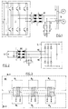
- 3 to 6 show exemplary embodiments for a drastic reduction in the number of components, these. Reduction takes place in that all chokes are combined into a single, common component BE, shown in broken lines in FIGS. 1 and 2.
- three windings L1, L2 and L3 are arranged on a rod 5 made of magnetic material, the number of turns of which are adapted to the specific requirements of the respective application. Regardless of the number of turns, it is true that the windings are wound as narrowly as possible on top of each other and that they are spatially separated from one another.
- the choice of magnetic material for rod 5 depends on the operating frequencies of the converter. For frequency converters, for example, nested iron sheets as well as iron powder or ferrite materials can be used.
- the winding starts of the windings L1 to L3 are each designated as terminal A and the output locks as terminal B. If you connect the terminals A of all three windings L1 to L3 with the output terminals 3 of the converter 1 (Fig. 1) and the terminals B with the connecting cable from the converter 1 to the induction machines 4, then the one shown in Fig. 3 and subsequently acts as Multiple choke designated unit BE on symmetrical and asymmetrical interference voltages as well as the device of Fig. 1st
- the multiple choke BE shown in FIG. 3 can thus be used to limit potential jumps between the lines and also with respect to the earth potential.
- the multiple choke BE shown in FIG. 3 contains a current-compensated choke and three symmetrical chokes acting as a series inductor, which are combined to form a single component.
- the choke is very saturation resistant to large currents due to the large air gap. This advantage is particularly useful for drive technology, since large currents can occur here for a short time due to changes in load.
- this contacting then acts for the wiring harnesses L1-L2 and L2-L3, the inductance, which results from the series connection of the two respective windings L1 and L2 or L2 and L3, and for the wiring harness L1-L3 is then only the leakage inductance is effective.
- this leakage inductance acts as a longitudinal inductance and limits short current rise times and potential jumps between the live lines. In individual cases, this solution can deliver satisfactory results.
- the device for use in four-wire networks with three phases and a common neutral conductor is expanded by an additional winding L N.
- the results that can be achieved with this multiple throttle BE are the same as those already described with reference to FIG. Analogous to the multiple choke of FIG. 3, a satisfactory solution can also be achieved in the construction of FIG. 4 by interchanging connections, for example the connections of the winding L N.
- FIG. 5 and 6 show two further variants, FIG. 5 showing a multiple choke BE for three-wire and FIG. 6 one for four-wire operation.
- the individual windings L1, L2 and L3 (Fig. 5) or L1, L2, L3 and L N (Fig. 6) are not on a rod-shaped but on a rectangular Core 6 arranged, which is divided by two air gaps 7 in two U-shaped, facing halves. This arrangement has the advantage that the largely closed magnetic circuit with the remaining residual air gap can generate significantly higher inductance values.
Landscapes
- Engineering & Computer Science (AREA)
- Power Engineering (AREA)
- Power Conversion In General (AREA)
- Emergency Protection Circuit Devices (AREA)
Applications Claiming Priority (3)
| Application Number | Priority Date | Filing Date | Title |
|---|---|---|---|
| CH01464/94A CH691720A5 (de) | 1994-05-11 | 1994-05-11 | Einrichtung zur Begrenzung der Aenderungsgeschwindigkeit von Strömen und Spannungen zwischen Leitungen oder gegenüber dem Erdpotential und Verwendung derselben. |
| CH146494 | 1994-05-11 | ||
| CH1464/94 | 1994-05-11 |
Publications (4)
| Publication Number | Publication Date |
|---|---|
| EP0682395A2 true EP0682395A2 (fr) | 1995-11-15 |
| EP0682395A3 EP0682395A3 (fr) | 1997-01-22 |
| EP0682395B1 EP0682395B1 (fr) | 2003-01-02 |
| EP0682395B2 EP0682395B2 (fr) | 2009-01-28 |
Family
ID=4211086
Family Applications (1)
| Application Number | Title | Priority Date | Filing Date |
|---|---|---|---|
| EP95106490A Expired - Lifetime EP0682395B2 (fr) | 1994-05-11 | 1995-04-28 | Dispositif pour limitation de la vitesse de changement des courants et tensions entre conducteurs ou vers la terre et procédé l'utilisant |
Country Status (4)
| Country | Link |
|---|---|
| EP (1) | EP0682395B2 (fr) |
| AT (1) | ATE230525T1 (fr) |
| CH (1) | CH691720A5 (fr) |
| DE (1) | DE59510516D1 (fr) |
Cited By (7)
| Publication number | Priority date | Publication date | Assignee | Title |
|---|---|---|---|---|
| WO1997048174A1 (fr) * | 1996-06-14 | 1997-12-18 | ALAMÄKI, Jarmo | Procede et appareil de filtrage du courant electrique fourni a un moteur |
| EP0899859A2 (fr) * | 1997-08-23 | 1999-03-03 | Asea Brown Boveri AG | Onduleur avec circuit intermédiaire de tension |
| DE19829424B4 (de) * | 1997-07-04 | 2007-12-06 | KS Techniques Société Anonyme | Gleichpoliges Filter |
| DE102008031296A1 (de) * | 2008-07-02 | 2009-08-20 | Siemens Aktiengesellschaft | Drosselspuleneinrichtung für einen Filterschaltkreis sowie Verwendung einer solchen und Filterschaltkreis |
| WO2010139382A1 (fr) * | 2009-06-03 | 2010-12-09 | Maschinenfabrik Reinhausen Gmbh | Dispositif permettant de vérifier des appareils de la technique de haute tension |
| CN111512545A (zh) * | 2017-12-21 | 2020-08-07 | 艾思玛太阳能技术股份公司 | Lc滤波器组件和具有这种lc滤波器组件的电气或电子设备 |
| US11522522B2 (en) * | 2019-09-02 | 2022-12-06 | Tdk Electronics Ag | Low-pass filter |
Families Citing this family (2)
| Publication number | Priority date | Publication date | Assignee | Title |
|---|---|---|---|---|
| DE102005031372A1 (de) * | 2005-07-05 | 2007-01-11 | Siemens Ag | Wechselrichter mit Sinusfilter |
| DE102008046576A1 (de) | 2008-09-10 | 2010-03-18 | Siemens Aktiengesellschaft | Dreiphasige Drosselspuleneinrichtung |
Citations (5)
| Publication number | Priority date | Publication date | Assignee | Title |
|---|---|---|---|---|
| GB1322433A (en) * | 1970-10-13 | 1973-07-04 | Siemens Ag | Radio interference suppression devices |
| DE2600765A1 (de) * | 1976-01-10 | 1977-07-14 | Licentia Gmbh | Siebdrossel zur minderung von stoerspannungen in stromversorgungen |
| DE3445879A1 (de) * | 1983-11-09 | 1986-06-19 | Vogt electronic AG, 8391 Erlau | Stromkompensierte ringkerndrossel mit erhoehter streuinduktivitaet |
| DE4135680A1 (de) * | 1991-10-30 | 1993-05-06 | Andreas Prof. Dr.-Ing.Habil. 7000 Stuttgart De Boehringer | Einrichtung zur begrenzung der aenderungsgeschwindigkeiten von ausgangsgroessen dreiphasiger, selbstgefuehrter wechselrichter mit gleichspannungszwischenkreis |
| EP0579962A1 (fr) * | 1992-06-22 | 1994-01-26 | Matsushita Electric Industrial Co., Ltd. | Bobine d'induction |
-
1994
- 1994-05-11 CH CH01464/94A patent/CH691720A5/de not_active IP Right Cessation
-
1995
- 1995-04-28 EP EP95106490A patent/EP0682395B2/fr not_active Expired - Lifetime
- 1995-04-28 DE DE59510516T patent/DE59510516D1/de not_active Expired - Lifetime
- 1995-04-28 AT AT95106490T patent/ATE230525T1/de not_active IP Right Cessation
Patent Citations (5)
| Publication number | Priority date | Publication date | Assignee | Title |
|---|---|---|---|---|
| GB1322433A (en) * | 1970-10-13 | 1973-07-04 | Siemens Ag | Radio interference suppression devices |
| DE2600765A1 (de) * | 1976-01-10 | 1977-07-14 | Licentia Gmbh | Siebdrossel zur minderung von stoerspannungen in stromversorgungen |
| DE3445879A1 (de) * | 1983-11-09 | 1986-06-19 | Vogt electronic AG, 8391 Erlau | Stromkompensierte ringkerndrossel mit erhoehter streuinduktivitaet |
| DE4135680A1 (de) * | 1991-10-30 | 1993-05-06 | Andreas Prof. Dr.-Ing.Habil. 7000 Stuttgart De Boehringer | Einrichtung zur begrenzung der aenderungsgeschwindigkeiten von ausgangsgroessen dreiphasiger, selbstgefuehrter wechselrichter mit gleichspannungszwischenkreis |
| EP0579962A1 (fr) * | 1992-06-22 | 1994-01-26 | Matsushita Electric Industrial Co., Ltd. | Bobine d'induction |
Non-Patent Citations (1)
| Title |
|---|
| 'Funk-Entstörung Datenbuch 1968/69', 1968, SIEMENS AG, DE Seiten 91,92, - 106 † |
Cited By (8)
| Publication number | Priority date | Publication date | Assignee | Title |
|---|---|---|---|---|
| WO1997048174A1 (fr) * | 1996-06-14 | 1997-12-18 | ALAMÄKI, Jarmo | Procede et appareil de filtrage du courant electrique fourni a un moteur |
| DE19829424B4 (de) * | 1997-07-04 | 2007-12-06 | KS Techniques Société Anonyme | Gleichpoliges Filter |
| EP0899859A2 (fr) * | 1997-08-23 | 1999-03-03 | Asea Brown Boveri AG | Onduleur avec circuit intermédiaire de tension |
| EP0899859A3 (fr) * | 1997-08-23 | 2000-06-07 | Asea Brown Boveri AG | Onduleur avec circuit intermédiaire de tension |
| DE102008031296A1 (de) * | 2008-07-02 | 2009-08-20 | Siemens Aktiengesellschaft | Drosselspuleneinrichtung für einen Filterschaltkreis sowie Verwendung einer solchen und Filterschaltkreis |
| WO2010139382A1 (fr) * | 2009-06-03 | 2010-12-09 | Maschinenfabrik Reinhausen Gmbh | Dispositif permettant de vérifier des appareils de la technique de haute tension |
| CN111512545A (zh) * | 2017-12-21 | 2020-08-07 | 艾思玛太阳能技术股份公司 | Lc滤波器组件和具有这种lc滤波器组件的电气或电子设备 |
| US11522522B2 (en) * | 2019-09-02 | 2022-12-06 | Tdk Electronics Ag | Low-pass filter |
Also Published As
| Publication number | Publication date |
|---|---|
| ATE230525T1 (de) | 2003-01-15 |
| CH691720A5 (de) | 2001-09-14 |
| EP0682395B1 (fr) | 2003-01-02 |
| EP0682395A3 (fr) | 1997-01-22 |
| DE59510516D1 (de) | 2003-02-06 |
| EP0682395B2 (fr) | 2009-01-28 |
Similar Documents
| Publication | Publication Date | Title |
|---|---|---|
| EP1145416B1 (fr) | Convertisseurs pour la transformation d'energie electrique | |
| DE1613695C2 (de) | Schaltungsanordnung zur Umrichtung einer Mehrphasenspannung in eine Wechselspannung niedriger Frequenz | |
| DE2306917B2 (de) | Drosselspule oder Transformator | |
| DE19630284A1 (de) | Antriebssystem für ein Schienenfahrzeug und Ansteuerverfahren hierzu | |
| EP0597409B1 (fr) | Véhicule multisystème | |
| EP0682402B1 (fr) | Dispositif pour la limitation de la pente des grandeurs de sortie d'un convertisseur auto-commuté à circuit intermédiaire à tension continue | |
| DE102005019215B4 (de) | Ausgangsfilter für einen gepulsten Stromrichter | |
| EP0682401B1 (fr) | Dispositif pour la limitation de la pente de la tension de sortie d'un convertisseur auto-commuté | |
| EP0682395B1 (fr) | Dispositif pour limitation de la vitesse de changement des courants et tensions entre conducteurs ou vers la terre et procédé l'utilisant | |
| EP1220431A1 (fr) | Amortissement des surhaussements de résonance d'un moteur électrique alimenté par un convertisseur avec circuit intermédiaire de tension | |
| DE102013208911A1 (de) | Mehrphasige Drossel mit integriertem Störungsunterdrückungstransformator | |
| EP1211788A1 (fr) | Amortissement des surhaussements de résonance d'un moteur électrique alimenté par un convertisseur avec circuit intermédiaire de tension | |
| AT502355B1 (de) | Stromversorgungseinrichtung für eine elektrische maschine | |
| EP3526889B1 (fr) | Ensemble inverseur avec un neutre à la terre | |
| EP3783630B1 (fr) | Dispositif de suppression d'une composante courant continu lors du fonctionnement d'un appareil électrique connecté à un réseau haute tension | |
| DE20311104U1 (de) | Umrichter mit Dämpfungseinrichtung zur Vermeidung von Resonanzen | |
| EP1217712A2 (fr) | Atténuation de résonances amplifiées dans un moteur alimenté par convertisseur à tension constante par amplification des pertes dans le domaine des fréquences de résonance | |
| WO2003085797A2 (fr) | Procede de transmission inductive d'energie electrique | |
| DE102015003225A1 (de) | Wechselrichter | |
| DE102008035529B4 (de) | Einrichtung zum Ansteuern eines Drehstrommotors, insbesondere eines Asynchronmotors | |
| EP4133565B1 (fr) | Dispositif filtrant | |
| DE19861015A1 (de) | Anordnung zur Einspeisung von elektrischem Strom in ein 3-phasiges Stromnetz | |
| DE29701914U1 (de) | Schaltungsanordnung zum direkten Umrichten elektrischer Energie | |
| WO2022002626A1 (fr) | Dispositif de filtrage et procédé pour faire fonctionner ce dispositif | |
| EP4115511A1 (fr) | Ensemble convertisseur |
Legal Events
| Date | Code | Title | Description |
|---|---|---|---|
| PUAI | Public reference made under article 153(3) epc to a published international application that has entered the european phase |
Free format text: ORIGINAL CODE: 0009012 |
|
| AK | Designated contracting states |
Kind code of ref document: A2 Designated state(s): AT BE DE DK FR GB IE IT NL |
|
| PUAL | Search report despatched |
Free format text: ORIGINAL CODE: 0009013 |
|
| AK | Designated contracting states |
Kind code of ref document: A3 Designated state(s): AT BE DE DK FR GB IE IT NL |
|
| 17P | Request for examination filed |
Effective date: 19970715 |
|
| 17Q | First examination report despatched |
Effective date: 19971204 |
|
| RAP1 | Party data changed (applicant data changed or rights of an application transferred) |
Owner name: SCHAFFNER EMV AG |
|
| GRAG | Despatch of communication of intention to grant |
Free format text: ORIGINAL CODE: EPIDOS AGRA |
|
| GRAG | Despatch of communication of intention to grant |
Free format text: ORIGINAL CODE: EPIDOS AGRA |
|
| GRAG | Despatch of communication of intention to grant |
Free format text: ORIGINAL CODE: EPIDOS AGRA |
|
| GRAH | Despatch of communication of intention to grant a patent |
Free format text: ORIGINAL CODE: EPIDOS IGRA |
|
| GRAH | Despatch of communication of intention to grant a patent |
Free format text: ORIGINAL CODE: EPIDOS IGRA |
|
| GRAA | (expected) grant |
Free format text: ORIGINAL CODE: 0009210 |
|
| AK | Designated contracting states |
Kind code of ref document: B1 Designated state(s): AT BE DE DK FR GB IE IT NL |
|
| PG25 | Lapsed in a contracting state [announced via postgrant information from national office to epo] |
Ref country code: NL Free format text: LAPSE BECAUSE OF FAILURE TO SUBMIT A TRANSLATION OF THE DESCRIPTION OR TO PAY THE FEE WITHIN THE PRESCRIBED TIME-LIMIT Effective date: 20030102 Ref country code: IE Free format text: LAPSE BECAUSE OF FAILURE TO SUBMIT A TRANSLATION OF THE DESCRIPTION OR TO PAY THE FEE WITHIN THE PRESCRIBED TIME-LIMIT Effective date: 20030102 Ref country code: FR Free format text: LAPSE BECAUSE OF FAILURE TO SUBMIT A TRANSLATION OF THE DESCRIPTION OR TO PAY THE FEE WITHIN THE PRESCRIBED TIME-LIMIT Effective date: 20030102 |
|
| REF | Corresponds to: |
Ref document number: 230525 Country of ref document: AT Date of ref document: 20030115 Kind code of ref document: T |
|
| REG | Reference to a national code |
Ref country code: GB Ref legal event code: FG4D Free format text: 20030102:NOT ENGLISH |
|
| REG | Reference to a national code |
Ref country code: IE Ref legal event code: FG4D Free format text: GERMAN |
|
| REF | Corresponds to: |
Ref document number: 59510516 Country of ref document: DE Date of ref document: 20030206 Kind code of ref document: P |
|
| GBT | Gb: translation of ep patent filed (gb section 77(6)(a)/1977) |
Effective date: 20030304 |
|
| PG25 | Lapsed in a contracting state [announced via postgrant information from national office to epo] |
Ref country code: DK Free format text: LAPSE BECAUSE OF FAILURE TO SUBMIT A TRANSLATION OF THE DESCRIPTION OR TO PAY THE FEE WITHIN THE PRESCRIBED TIME-LIMIT Effective date: 20030402 |
|
| PG25 | Lapsed in a contracting state [announced via postgrant information from national office to epo] |
Ref country code: AT Free format text: LAPSE BECAUSE OF NON-PAYMENT OF DUE FEES Effective date: 20030428 |
|
| PG25 | Lapsed in a contracting state [announced via postgrant information from national office to epo] |
Ref country code: BE Free format text: LAPSE BECAUSE OF NON-PAYMENT OF DUE FEES Effective date: 20030430 |
|
| PLBQ | Unpublished change to opponent data |
Free format text: ORIGINAL CODE: EPIDOS OPPO |
|
| PLBI | Opposition filed |
Free format text: ORIGINAL CODE: 0009260 |
|
| REG | Reference to a national code |
Ref country code: IE Ref legal event code: FD4D Ref document number: 0682395E Country of ref document: IE |
|
| 26 | Opposition filed |
Opponent name: EPCOS AG Effective date: 20030702 |
|
| BERE | Be: lapsed |
Owner name: *SCHAFFNER EMV A.G. Effective date: 20030430 |
|
| PLAX | Notice of opposition and request to file observation + time limit sent |
Free format text: ORIGINAL CODE: EPIDOSNOBS2 |
|
| EN | Fr: translation not filed | ||
| PLAX | Notice of opposition and request to file observation + time limit sent |
Free format text: ORIGINAL CODE: EPIDOSNOBS2 |
|
| PLAX | Notice of opposition and request to file observation + time limit sent |
Free format text: ORIGINAL CODE: EPIDOSNOBS2 |
|
| PLBB | Reply of patent proprietor to notice(s) of opposition received |
Free format text: ORIGINAL CODE: EPIDOSNOBS3 |
|
| PLCK | Communication despatched that opposition was rejected |
Free format text: ORIGINAL CODE: EPIDOSNREJ1 |
|
| APBP | Date of receipt of notice of appeal recorded |
Free format text: ORIGINAL CODE: EPIDOSNNOA2O |
|
| APAH | Appeal reference modified |
Free format text: ORIGINAL CODE: EPIDOSCREFNO |
|
| APBQ | Date of receipt of statement of grounds of appeal recorded |
Free format text: ORIGINAL CODE: EPIDOSNNOA3O |
|
| APBU | Appeal procedure closed |
Free format text: ORIGINAL CODE: EPIDOSNNOA9O |
|
| PGFP | Annual fee paid to national office [announced via postgrant information from national office to epo] |
Ref country code: IT Payment date: 20080426 Year of fee payment: 14 |
|
| PUAH | Patent maintained in amended form |
Free format text: ORIGINAL CODE: 0009272 |
|
| STAA | Information on the status of an ep patent application or granted ep patent |
Free format text: STATUS: PATENT MAINTAINED AS AMENDED |
|
| PGFP | Annual fee paid to national office [announced via postgrant information from national office to epo] |
Ref country code: GB Payment date: 20080421 Year of fee payment: 14 |
|
| 27A | Patent maintained in amended form |
Effective date: 20090128 |
|
| AK | Designated contracting states |
Kind code of ref document: B2 Designated state(s): AT BE DE DK FR GB IE IT NL |
|
| GBPC | Gb: european patent ceased through non-payment of renewal fee |
Effective date: 20090428 |
|
| PG25 | Lapsed in a contracting state [announced via postgrant information from national office to epo] |
Ref country code: GB Free format text: LAPSE BECAUSE OF NON-PAYMENT OF DUE FEES Effective date: 20090428 |
|
| PG25 | Lapsed in a contracting state [announced via postgrant information from national office to epo] |
Ref country code: IT Free format text: LAPSE BECAUSE OF NON-PAYMENT OF DUE FEES Effective date: 20090428 |
|
| PGFP | Annual fee paid to national office [announced via postgrant information from national office to epo] |
Ref country code: DE Payment date: 20130419 Year of fee payment: 19 |
|
| REG | Reference to a national code |
Ref country code: DE Ref legal event code: R119 Ref document number: 59510516 Country of ref document: DE |
|
| REG | Reference to a national code |
Ref country code: DE Ref legal event code: R119 Ref document number: 59510516 Country of ref document: DE Effective date: 20141101 |
|
| PG25 | Lapsed in a contracting state [announced via postgrant information from national office to epo] |
Ref country code: DE Free format text: LAPSE BECAUSE OF NON-PAYMENT OF DUE FEES Effective date: 20141101 |