EP0681348A2 - Data connector strain relief assembly - Google Patents
Data connector strain relief assembly Download PDFInfo
- Publication number
- EP0681348A2 EP0681348A2 EP95303039A EP95303039A EP0681348A2 EP 0681348 A2 EP0681348 A2 EP 0681348A2 EP 95303039 A EP95303039 A EP 95303039A EP 95303039 A EP95303039 A EP 95303039A EP 0681348 A2 EP0681348 A2 EP 0681348A2
- Authority
- EP
- European Patent Office
- Prior art keywords
- cable
- strain relief
- channel
- filler block
- electrical connector
- Prior art date
- Legal status (The legal status is an assumption and is not a legal conclusion. Google has not performed a legal analysis and makes no representation as to the accuracy of the status listed.)
- Granted
Links
Images


Classifications
-
- H—ELECTRICITY
- H01—ELECTRIC ELEMENTS
- H01R—ELECTRICALLY-CONDUCTIVE CONNECTIONS; STRUCTURAL ASSOCIATIONS OF A PLURALITY OF MUTUALLY-INSULATED ELECTRICAL CONNECTING ELEMENTS; COUPLING DEVICES; CURRENT COLLECTORS
- H01R13/00—Details of coupling devices of the kinds covered by groups H01R12/70 or H01R24/00 - H01R33/00
- H01R13/58—Means for relieving strain on wire connection, e.g. cord grip, for avoiding loosening of connections between wires and terminals within a coupling device terminating a cable
- H01R13/5837—Means for relieving strain on wire connection, e.g. cord grip, for avoiding loosening of connections between wires and terminals within a coupling device terminating a cable specially adapted for accommodating various sized cables
-
- H—ELECTRICITY
- H01—ELECTRIC ELEMENTS
- H01R—ELECTRICALLY-CONDUCTIVE CONNECTIONS; STRUCTURAL ASSOCIATIONS OF A PLURALITY OF MUTUALLY-INSULATED ELECTRICAL CONNECTING ELEMENTS; COUPLING DEVICES; CURRENT COLLECTORS
- H01R13/00—Details of coupling devices of the kinds covered by groups H01R12/70 or H01R24/00 - H01R33/00
- H01R13/58—Means for relieving strain on wire connection, e.g. cord grip, for avoiding loosening of connections between wires and terminals within a coupling device terminating a cable
- H01R13/5841—Means for relieving strain on wire connection, e.g. cord grip, for avoiding loosening of connections between wires and terminals within a coupling device terminating a cable allowing different orientations of the cable with respect to the coupling direction
-
- H—ELECTRICITY
- H01—ELECTRIC ELEMENTS
- H01R—ELECTRICALLY-CONDUCTIVE CONNECTIONS; STRUCTURAL ASSOCIATIONS OF A PLURALITY OF MUTUALLY-INSULATED ELECTRICAL CONNECTING ELEMENTS; COUPLING DEVICES; CURRENT COLLECTORS
- H01R13/00—Details of coupling devices of the kinds covered by groups H01R12/70 or H01R24/00 - H01R33/00
- H01R13/58—Means for relieving strain on wire connection, e.g. cord grip, for avoiding loosening of connections between wires and terminals within a coupling device terminating a cable
- H01R13/5804—Means for relieving strain on wire connection, e.g. cord grip, for avoiding loosening of connections between wires and terminals within a coupling device terminating a cable comprising a separate cable clamping part
-
- H—ELECTRICITY
- H01—ELECTRIC ELEMENTS
- H01R—ELECTRICALLY-CONDUCTIVE CONNECTIONS; STRUCTURAL ASSOCIATIONS OF A PLURALITY OF MUTUALLY-INSULATED ELECTRICAL CONNECTING ELEMENTS; COUPLING DEVICES; CURRENT COLLECTORS
- H01R13/00—Details of coupling devices of the kinds covered by groups H01R12/70 or H01R24/00 - H01R33/00
- H01R13/58—Means for relieving strain on wire connection, e.g. cord grip, for avoiding loosening of connections between wires and terminals within a coupling device terminating a cable
- H01R13/582—Means for relieving strain on wire connection, e.g. cord grip, for avoiding loosening of connections between wires and terminals within a coupling device terminating a cable the cable being clamped between assembled parts of the housing
- H01R13/5829—Means for relieving strain on wire connection, e.g. cord grip, for avoiding loosening of connections between wires and terminals within a coupling device terminating a cable the cable being clamped between assembled parts of the housing the clamping part being flexibly or hingedly connected to the housing
-
- H—ELECTRICITY
- H01—ELECTRIC ELEMENTS
- H01R—ELECTRICALLY-CONDUCTIVE CONNECTIONS; STRUCTURAL ASSOCIATIONS OF A PLURALITY OF MUTUALLY-INSULATED ELECTRICAL CONNECTING ELEMENTS; COUPLING DEVICES; CURRENT COLLECTORS
- H01R2201/00—Connectors or connections adapted for particular applications
- H01R2201/04—Connectors or connections adapted for particular applications for network, e.g. LAN connectors
-
- H—ELECTRICITY
- H01—ELECTRIC ELEMENTS
- H01R—ELECTRICALLY-CONDUCTIVE CONNECTIONS; STRUCTURAL ASSOCIATIONS OF A PLURALITY OF MUTUALLY-INSULATED ELECTRICAL CONNECTING ELEMENTS; COUPLING DEVICES; CURRENT COLLECTORS
- H01R2201/00—Connectors or connections adapted for particular applications
- H01R2201/16—Connectors or connections adapted for particular applications for telephony
Definitions
- the present invention relates generally to electrical data connectors. More particularly the present invention relates to an improved strain relief assembly for securing a jacketed multi-conductor cable terminated by an electrical data connector.
- Electrical data connectors are commonly employed to terminate signal carrying jacketed multi-conductor electrical cables which are used to connect various components of a data/communication system. Examples of electrical data connectors are shown in U.S. Patent Nos. 4,449,788, 4,501,459 and 4,619,494. Each of these data connectors includes a connector housing which supports a plurality of insulation displacement type electrical contacts. The individual conductors of the multi-conductor cable are terminated by the contacts for electrical connection therewith. The jacketed cable extends externally of the connector housing for extension to another component of the system. As interconnection is dependent upon a good termination of the conductors of the cable with the contacts, it is necessary to assure that any strain placed on the jacketed cable is not transmitted to the contact termination. Such strain could cause dislodgement of one or more of the conductors from the contacts. This would result in failure of the connector and accordingly the inoperability of the component to which it is terminated.
- the electrical connector art and specifically the data connector art has seen a wide variety of strain relief devices employed both internally and externally of the connector having to provide strain relief to the cable extending therefrom.
- Each of the above-identified patents shows a technique for providing cable strain relief. While each of the various cable strain relief devices shown, attempt to adequately support the jacketed cable in the connector, it has been found that these prior art devices may include many parts and therefore may be difficult to assemble. Also, such devices do not adequately accommodate a range of cable sizes in a single strain relief device. Further, these prior art devices may not protect against both inward and outward movement of the cable in the connector, as well as potential rotation of the cable in the connector.
- the present invention provides an electrical connector for terminating jacketed multi-conductor cables of at least two differing cable jacket diameters.
- the connector includes a connector housing for accommodating an end extent of either said cable.
- the connector includes a cable passage port therethrough permitting ingress and egress of the cables.
- the cable strain relief assembly frictionally engages and secures either of the cable.
- the strain relief assembly includes a strain relief body which is removably positionable in the connector housing adjacent the cable passage port.
- the strain relief body defines first and second cable channels, each channel accessible alternatively for accommodating exclusively one of the cables.
- the strain relief assembly further includes a channel filler block insertable into the first channel to fill the first channel preventing cable accommodation therein and rendering the second channel accessible for cable accommodation.
- the strain relief assembly additionally includes a strain relief plug insertably accommodated in the strain relief body. The plug is positioned to engage either of the cables positioned in either the first channel or second channel whereby either cable is supported in strain relief fashion between the strain relief body and the strain relief plug.
- the strain relief body includes a generally U-shaped member defining both the first and second cable channels.
- the first channel is defined by a recess in the bottom wall of the U-shaped member and the channel filler block is insertable into the recess in the bottom wall of the U-shaped member to close off the first channel rendering accessible only the second channel.
- the connector housing includes plural cable passage ports permitting cable passage at plural different locations with respect to the connector housing.
- the strain relief body is removably positionable in the connector housing and includes a cable accommodating channel positionable adjacent one of the plural cable passage ports.
- the strain relief body further includes port closing portions positionable adjacent the other ones of said plural cable passage ports for excluding cable passage therethrough.
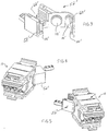
- Figure 1 shows in exploded perspective view, the data connector including a portion of the strain relief assembly of the present invention.
- Figure 2 shows in exploded perspective view, the strain relief assembly of Figure 1 removed from the connector.
- Figure 3 is a perspective showing of a further embodiment of a strain relief body of the strain relief assembly of the present invention.
- FIGs 4 and 5 are perspective showings of the data connector of Figure 1 including the further embodiment of the strain relief body of Figure 3.
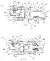
- Figures 6 and 7 are side elevational showings, partially in section, of the electrical connector and strain relief assembly of the present invention terminating cables having two differing cable diameters respectively.
- Data connector 10 is of the type used to terminate a multi-conductor jacketed data cable 12.
- Connector 10 is substantially similar to the connector shown in U.S. Patent No. 4,619,494 issued October 28, 1986 entitled “Shielded Electrical Connector", which is assigned to the Assignee of the present invention and which is incorporated by reference herein for all purposes.
- Connector 10 comprises a generally elongate rectangular insulative housing 14 defined by a cover 16 and a base 18. Connector 10 supports between cover 16 and base 18 a termination subassembly 20. Housing 14 may include an electrical shield (not shown) which provides for effective shielding of connector 10 from electro-magnetic interference and radio frequency interference which is prevalent in the environment in which connector 10 is used.
- Cover 16 includes a generally elongate planar lid 22 which supports a latching mechanism 24.
- Base 18 includes a bottom base wall 26 and an upstanding side wall 28 which partially surrounds base wall 26. Side wall 28 includes a plurality of generally U-shaped cable entry ports 30 which provide for passage of cable 12 into housing 14.
- five cable entry ports 30 are positioned such that cable 12 may extend out of housing 14 directly rearwardly through port 30a or offset to either side at a 45° angle through ports 30b and 30c or at a 90° angle through ports 30d and 30e.
- Base wall 26 further includes an additional latching mechanism 32 which in combination with latching mechanism 24 of cover 16 permits interconnection of connector 10 with another similarly constructed connector in a manner described in greater detail in the above-identified '494 patent.
- Termination subassembly 20 which is housed between cover 16 and base 18, includes an insulative contact holder 36 which support a plurality of insulation displacing electrical contacts 40 which individually terminate the conductors of multi-conductor cable 12. Termination subassembly also includes a conductor support block 41 for supporting the conductors of the multi-conductor cable 12 for termination with contacts 40. The conductor support block 41 may also support shunt bars 42 for shunting one contact 40 to another.
- the electrical termination of cable 12 within data connector 10 is more fully described in the above-identified '494 patent.
- Strain relief assembly 50 includes a strain relief body 52 and a strain relief plug 54 which is insertably accommodated by strain relief body 52 to secure cable 12 therebetween as will be described in further detail hereinbelow.
- Strain relief body 52 includes a central body portion 56 which is generally a U-shaped member and includes a pair of curved frontwardly directed arms 58 and 60 extending therefrom.
- Central body portion 56 includes a bottom wall 62 and a pair of spaced apart side walls 64 and 66 which extend upwardly from bottom wall 62.
- Arms 58 and 60 extend outwardly respectively from side walls 64 and 66.
- Bottom wall 62 and side walls 64 and 66 define generally an open ended cable passage 68 which together with strain relief plug 54 define a fully enclosed bounded region for accommodating cable 12.
- the strain relief assembly 50 of the present invention is designed to accommodate cables of at least two differing diameters.
- the multi-conductor cable will generally be denoted by reference numeral 12.
- the larger diameter cable will be denoted by reference numeral 12a, while the smaller diameter cable will be denoted by reference numeral 12b.
- the cable jacket will be denoted by reference numeral 13.
- Central body portion 56 defining cable passage 68 includes a recess 70 centrally positioned and extending partially through bottom wall 62.
- Recess 70 defines a first cable channel 72 which permits accommodation of the cable 12a of a relatively large diameter cable, such as shown in Figure 6.
- a bottom surface 76 of recess 70 includes a plurality of spaced apart transversely extending raised ridges 74 which are engagable with cable 12a for frictional securement of the jacket 13 therein.
- the present invention provides a filler block 76 which is attached to central body portion 56.
- Filler block 76 is generally a rectangular member having a first planar surface 82 and an opposed second planar surface 86.
- Filler block 76 is integrally formed with strain relief body 52 and is tethered thereto by a flexible hinge 78.
- Filler block 76 is sized to fit within and fill recess 70. In order to use filler block 76 the filler block is folded about hinge 78 and is inserted into recess 70.
- a plurality of transverse channels 80 on first planar surface 82 of filler block 76 are engagable with raised ridges 74 in recess 70 to provide proper positioning of filler block 76 in recess 70.
- central body portion 56 of strain relief body 52 defines a second channel 84 raised above first channel 72 which is partially defined by a second planar surface 86 of filler block 76.
- Second planar surface 86 also includes a plurality of raised ridges 88 which, as shown in Figure 7, are positioned for frictional engagement with jacket 13 of smaller diameter cable 12b.
- the strain relief assembly 50 of the present invention permits accommodation of cables 12 having at least two differing cable diameters by providing a first channel 72 for cables of larger diameter and a second channel 84 for cables of smaller diameter.
- first channel 72 for cable 12a of larger diameter filler block 76 may be removed from strain relief body 52.
- Hinge 78 is designed to be frangible to permit such easy removal.
- strain relief plug 54 is movably supported over strain relief body 52.
- Strain relief plug 54 is generally a U-shaped member having a top wall 88, a pair of depending side walls 90 and 92.
- Strain relief plug 54 includes a pair of longitudinally extending latch walls 94 and 96 which are spaced from and extend along side walls 90 and 92 respectively.
- a pair of transverse back walls 98 and 100 support respectively latch walls 94 an 96 for extension in a cantilevered manner therefrom.
- the interior surfaces 94a and 96a of latch walls 94 and 96 respectively, include tooth-like serrations 95a therealong.
- exterior surfaces 90a and 92a of side walls 90 and 92 respectively which face the interior surfaces 94a and 96a also include similar tooth-like serrations 95b. These serrations 95a and 95b permit movable locking engagement of strain relief plug 54 with strain relief body 52 as will be now more fully described.
- Strain relief body 52 includes a pair of interiorly positioned locking walls 102 and 104 which extend upwardly from bottom wall 62. Walls 102 and 104 are spaced inwardly from side walls 64 and 66 respectively. The spacing between the respective side walls 64 and 66 and locking walls 102 and 104 permit accommodation of latch walls 94 and 96 therebetween. Opposed surfaces of locking walls 102 and 104 include tooth-like serrations 95c similar to the serrations 95a and 95b of strain relief plug 54. In order to properly position and guide strain relief plug 54 into strain relief body 52, the internal surface of each of side walls 64 and 66 includes guide tracks 64a and 66a respectively.
- Strain relief plug 54 is designed to be movably accommodated within strain relief body 52. Ribs 94b and 96b are insertable into guide tracks 64a and 66a with teeth-like serrations 95c of locking walls 102 and 104 interengaging, in a tooth-like fashion, the serrations 95a and 95b of side walls 90 and 92 and latch walls 94 and 96 so as to securely movably position strain relief plug 54 with respect to strain relief body 52.
- strain relief plug 54 may be moved with respect to strain relief body 52 until strain relief plug 54 engages in a frictional manner, jacket 13 of either cable 12a or 12b supported therebetween.
- the interior U-shaped surface of strain relief plug 54 may include a plurality of transversely extending ridges 106 similar to ridges 74 for frictionally securing the cable jacket.
- Strain relief plug 54 is designed to be inserted into strain relief body 52 until it bottoms out in strain relief body 52. This will occur regardless of the diameter of the cable secured therebetween. Thus, there is no tendency to over or under insert strain relief plug 54 in strain relief body 52.
- strain relief plug 54 may be inserted to the same position with respect to strain relief body 52 and still frictionally secure each of the cables therebetween.
- the frictional securement of cables 12a and 12b between strain relief plug 54 and strain relief body 52 prevents both insertion and withdrawal thereof with respect to data connector 10 as well as rotational movement therein.
- strain relief assembly 50 of the present invention is shown in Figures 1 and 2.
- side wall 28 of base 18 of data connector 10 includes a plurality of generally U-shaped cable entry ports 30 which permit accommodation of cable 12 at multiple positions. However in use, only one cable entry port 30 is employed with any given data connector configuration. Thus it is necessary to close off the unused ports of housing 14.
- Strain relief assembly 50 of the present invention provides integrally therewith means for closing off the unused cable entry ports 30.
- port 30a extending directly rearwardly from data connector 10 is employed for cable entry, thus cable passage 68 of strain relief body 52 is aligned with that cable entry port 30a.
- Arms 58 and 60 of strain relief body 52 provide for the closure of the remaining cable entry ports 30b-e.
- Arms 58 and 60 extend generally along curved side wall 28 of base 18 to overlie the remaining cable entry ports 30b-e when strain relief body is positioned within housing 14.
- arms 58 and 60 include a plurality of inwardly directed protrusions 110 which fit within the U-shaped cable entry ports 30.
- protrusions 110 are generally oval in shape, however other suitable shapes may be employed. Protrusions 110 securely fit within U-shaped ports 30 and help secure strain relief body 52 in housing 14. Thus arms 58 and 60 together with protrusions 110 close off all unused cable entry ports 30 providing cable access only through a single port which supports cable passage 68 of strain relief body 52.
- the cable entry port 30a is positioned directly rearwardly of data connector 10. This may be referred to a "straight through" or 180° cable exit. However, any of the other cable entry ports 30b-e may also be employed.
- the present invention contemplates modifications to strain relief body 54 to accommodate other directions of cable entry.
- strain relief body 52 includes a cable passage 68' which is positioned to be adjacent one of the cable ports 30b or 30c to either side of the cable port 30a extending directly rearwardly of data connector 10. As will be described in further detail hereinbelow, strain relief body 52' may be used to access either port 30b or 30c on either side of rearwardly extending port 30a.
- strain relief body 52' functions identically to strain relief body 52 of the previously described embodiment.
- strain relief plug 54 ( Figure 2) may be used with either embodiment shown herein.
- Strain relief body 52 may be used to access either 45° cable entry port 30b or 30c by employing strain relief body 52' in one orientation or by inverting strain relief body 52' to access the other 45° port. Such dual orientations are shown in Figures 4 and 5. Thus strain relief body 52' may be employed to access two differing cable entry ports 30b and 30c.
- strain relief body may be constructed to access the remaining two ports 30d and 30e which extend at 90° from data connector 10. Such strain relief body would also include structure to close off the unused ports.
- strain relief body 52 or 52' is inserted within housing 14
- cable 12 may be terminated within housing 14 ( Figures 6 and 7). Cable 12 is positioned to extend out of the appropriate port with strain relief being provided by strain relief assembly 50. Cover 16 may then be snapped onto base 18 to assemble data connector 10 which is now usable for interconnection purposes.
Abstract
Description
- The present invention relates generally to electrical data connectors. More particularly the present invention relates to an improved strain relief assembly for securing a jacketed multi-conductor cable terminated by an electrical data connector.
- Electrical data connectors are commonly employed to terminate signal carrying jacketed multi-conductor electrical cables which are used to connect various components of a data/communication system. Examples of electrical data connectors are shown in U.S. Patent Nos. 4,449,788, 4,501,459 and 4,619,494. Each of these data connectors includes a connector housing which supports a plurality of insulation displacement type electrical contacts. The individual conductors of the multi-conductor cable are terminated by the contacts for electrical connection therewith. The jacketed cable extends externally of the connector housing for extension to another component of the system. As interconnection is dependent upon a good termination of the conductors of the cable with the contacts, it is necessary to assure that any strain placed on the jacketed cable is not transmitted to the contact termination. Such strain could cause dislodgement of one or more of the conductors from the contacts. This would result in failure of the connector and accordingly the inoperability of the component to which it is terminated.
- The electrical connector art and specifically the data connector art, has seen a wide variety of strain relief devices employed both internally and externally of the connector having to provide strain relief to the cable extending therefrom. Each of the above-identified patents shows a technique for providing cable strain relief. While each of the various cable strain relief devices shown, attempt to adequately support the jacketed cable in the connector, it has been found that these prior art devices may include many parts and therefore may be difficult to assemble. Also, such devices do not adequately accommodate a range of cable sizes in a single strain relief device. Further, these prior art devices may not protect against both inward and outward movement of the cable in the connector, as well as potential rotation of the cable in the connector.
- It is therefore desirable to provide an improved strain relief device for use with a data connector which is easy to assemble, provides superior strain relief and which accommodates a range of cable sizes.
- It is an object of the present invention to provide an electrical data connector for terminating jacketed multi-conductor electrical cable.
- It is further object of the present invention to provide an improved strain relief for securing the jacketed multi-conductor cable in the connector housing.
- It is a still further object of the present invention to provide an electrical connector strain relief device which will accommodate a range of cable sizes and which will prevent cable movement both into and out of the connector as well as prevent rotation of the cable in the connector.
- In the efficient attainment of these and other objects the present invention provides an electrical connector for terminating jacketed multi-conductor cables of at least two differing cable jacket diameters. The connector includes a connector housing for accommodating an end extent of either said cable. The connector includes a cable passage port therethrough permitting ingress and egress of the cables. The cable strain relief assembly frictionally engages and secures either of the cable. The strain relief assembly includes a strain relief body which is removably positionable in the connector housing adjacent the cable passage port. The strain relief body defines first and second cable channels, each channel accessible alternatively for accommodating exclusively one of the cables. The strain relief assembly further includes a channel filler block insertable into the first channel to fill the first channel preventing cable accommodation therein and rendering the second channel accessible for cable accommodation. The strain relief assembly additionally includes a strain relief plug insertably accommodated in the strain relief body. The plug is positioned to engage either of the cables positioned in either the first channel or second channel whereby either cable is supported in strain relief fashion between the strain relief body and the strain relief plug.
- As more particularly described by way of the preferred embodiment herein the strain relief body includes a generally U-shaped member defining both the first and second cable channels. The first channel is defined by a recess in the bottom wall of the U-shaped member and the channel filler block is insertable into the recess in the bottom wall of the U-shaped member to close off the first channel rendering accessible only the second channel.
- In a further aspect of the present invention, the connector housing includes plural cable passage ports permitting cable passage at plural different locations with respect to the connector housing. The strain relief body is removably positionable in the connector housing and includes a cable accommodating channel positionable adjacent one of the plural cable passage ports. The strain relief body further includes port closing portions positionable adjacent the other ones of said plural cable passage ports for excluding cable passage therethrough.
- Figure 1 shows in exploded perspective view, the data connector including a portion of the strain relief assembly of the present invention.
- Figure 2 shows in exploded perspective view, the strain relief assembly of Figure 1 removed from the connector.
- Figure 3 is a perspective showing of a further embodiment of a strain relief body of the strain relief assembly of the present invention.
- Figures 4 and 5 are perspective showings of the data connector of Figure 1 including the further embodiment of the strain relief body of Figure 3.
- Figures 6 and 7 are side elevational showings, partially in section, of the electrical connector and strain relief assembly of the present invention terminating cables having two differing cable diameters respectively.
- Referring to Figures 1, 6 and 7, a shielded
electrical data connector 10 of the present invention is shown.Data connector 10 is of the type used to terminate a multi-conductor jacketeddata cable 12.Connector 10 is substantially similar to the connector shown in U.S. Patent No. 4,619,494 issued October 28, 1986 entitled "Shielded Electrical Connector", which is assigned to the Assignee of the present invention and which is incorporated by reference herein for all purposes. -
Connector 10 comprises a generally elongate rectangularinsulative housing 14 defined by acover 16 and abase 18.Connector 10 supports betweencover 16 and base 18 a termination subassembly 20.Housing 14 may include an electrical shield (not shown) which provides for effective shielding ofconnector 10 from electro-magnetic interference and radio frequency interference which is prevalent in the environment in whichconnector 10 is used.Cover 16 includes a generally elongateplanar lid 22 which supports alatching mechanism 24.Base 18 includes abottom base wall 26 and anupstanding side wall 28 which partially surroundsbase wall 26.Side wall 28 includes a plurality of generally U-shaped cable entry ports 30 which provide for passage ofcable 12 intohousing 14. In the present illustrative embodiment, five cable entry ports 30 are positioned such thatcable 12 may extend out ofhousing 14 directly rearwardly throughport 30a or offset to either side at a 45° angle through ports 30b and 30c or at a 90° angle throughports -
Base wall 26 further includes anadditional latching mechanism 32 which in combination withlatching mechanism 24 ofcover 16 permits interconnection ofconnector 10 with another similarly constructed connector in a manner described in greater detail in the above-identified '494 patent. -
Termination subassembly 20, which is housed betweencover 16 andbase 18, includes aninsulative contact holder 36 which support a plurality of insulation displacingelectrical contacts 40 which individually terminate the conductors ofmulti-conductor cable 12. Termination subassembly also includes aconductor support block 41 for supporting the conductors of themulti-conductor cable 12 for termination withcontacts 40. Theconductor support block 41 may also supportshunt bars 42 for shunting onecontact 40 to another. The electrical termination ofcable 12 withindata connector 10 is more fully described in the above-identified '494 patent. - The present invention is directed primarily to an improved
strain relief assembly 50 shown removed fromdata connector 10 in Figure 2.Strain relief assembly 50 includes astrain relief body 52 and astrain relief plug 54 which is insertably accommodated bystrain relief body 52 to securecable 12 therebetween as will be described in further detail hereinbelow.Strain relief body 52 includes a central body portion 56 which is generally a U-shaped member and includes a pair of curved frontwardly directedarms bottom wall 62 and a pair of spaced apartside walls bottom wall 62.Arms side walls Bottom wall 62 andside walls ended cable passage 68 which together withstrain relief plug 54 define a fully enclosed bounded region for accommodatingcable 12. - With reference now to Figures 2, 6 and 7, it can be seen that the
strain relief assembly 50 of the present invention is designed to accommodate cables of at least two differing diameters. For ease of description, the multi-conductor cable will generally be denoted byreference numeral 12. The larger diameter cable will be denoted by reference numeral 12a, while the smaller diameter cable will be denoted by reference numeral 12b. The cable jacket will be denoted byreference numeral 13. - Central body portion 56
defining cable passage 68 includes arecess 70 centrally positioned and extending partially throughbottom wall 62.Recess 70 defines afirst cable channel 72 which permits accommodation of the cable 12a of a relatively large diameter cable, such as shown in Figure 6. Abottom surface 76 ofrecess 70 includes a plurality of spaced apart transversely extending raisedridges 74 which are engagable with cable 12a for frictional securement of thejacket 13 therein. - In order to accommodate in strain relief fashion, a cable 12b having a smaller diameter, such as that shown in Figure 7, the present invention provides a
filler block 76 which is attached to central body portion 56.Filler block 76 is generally a rectangular member having a firstplanar surface 82 and an opposed second planar surface 86.Filler block 76 is integrally formed withstrain relief body 52 and is tethered thereto by aflexible hinge 78.Filler block 76 is sized to fit within and fillrecess 70. In order to usefiller block 76 the filler block is folded abouthinge 78 and is inserted intorecess 70. A plurality of transverse channels 80 on firstplanar surface 82 offiller block 76 are engagable with raisedridges 74 inrecess 70 to provide proper positioning offiller block 76 inrecess 70. Withfiller block 76 inserted inrecess 70, central body portion 56 ofstrain relief body 52 defines asecond channel 84 raised abovefirst channel 72 which is partially defined by a second planar surface 86 offiller block 76. Second planar surface 86 also includes a plurality of raisedridges 88 which, as shown in Figure 7, are positioned for frictional engagement withjacket 13 of smaller diameter cable 12b. - The
strain relief assembly 50 of the present invention permits accommodation ofcables 12 having at least two differing cable diameters by providing afirst channel 72 for cables of larger diameter and asecond channel 84 for cables of smaller diameter. When employingfirst channel 72 for cable 12a of larger diameter,filler block 76 may be removed fromstrain relief body 52.Hinge 78 is designed to be frangible to permit such easy removal. - In order to securely frictionally retain either cable 12a or 12b within
cable passage 68,strain relief plug 54 is movably supported overstrain relief body 52.Strain relief plug 54 is generally a U-shaped member having atop wall 88, a pair of dependingside walls 90 and 92.Strain relief plug 54 includes a pair of longitudinally extendinglatch walls side walls 90 and 92 respectively. A pair oftransverse back walls walls 94 an 96 for extension in a cantilevered manner therefrom. The interior surfaces 94a and 96a oflatch walls like serrations 95a therealong. Further, theexterior surfaces side walls 90 and 92 respectively which face the interior surfaces 94a and 96a also include similar tooth-like serrations 95b. Theseserrations 95a and 95b permit movable locking engagement ofstrain relief plug 54 withstrain relief body 52 as will be now more fully described. -
Strain relief body 52 includes a pair of interiorly positioned lockingwalls bottom wall 62.Walls side walls respective side walls walls latch walls walls like serrations 95c similar to theserrations 95a and 95b ofstrain relief plug 54. In order to properly position and guidestrain relief plug 54 intostrain relief body 52, the internal surface of each ofside walls ribs 94b and 96b on the external surface oflatch walls Strain relief plug 54 is designed to be movably accommodated withinstrain relief body 52.Ribs 94b and 96b are insertable intoguide tracks 64a and 66a with teeth-like serrations 95c of lockingwalls serrations 95a and 95b ofside walls 90 and 92 andlatch walls strain relief plug 54 with respect to strainrelief body 52. - As shown with respect to Figures 6 and 7,
strain relief plug 54 may be moved with respect to strainrelief body 52 untilstrain relief plug 54 engages in a frictional manner,jacket 13 of either cable 12a or 12b supported therebetween. The interior U-shaped surface ofstrain relief plug 54 may include a plurality of transversely extendingridges 106 similar toridges 74 for frictionally securing the cable jacket.Strain relief plug 54 is designed to be inserted intostrain relief body 52 until it bottoms out instrain relief body 52. This will occur regardless of the diameter of the cable secured therebetween. Thus, there is no tendency to over or under insertstrain relief plug 54 instrain relief body 52. - As shown particularly in Figures 6 and 7, as the larger diameter cable 12a is supported in first channel 72 (Figure 6) and as the smaller diameter cable 12b (Figure 7) is supported in
second channel 84 which is raised fromfirst channel 72 by use offiller block 76, thestrain relief plug 54 may be inserted to the same position with respect to strainrelief body 52 and still frictionally secure each of the cables therebetween. The frictional securement of cables 12a and 12b betweenstrain relief plug 54 andstrain relief body 52 prevents both insertion and withdrawal thereof with respect todata connector 10 as well as rotational movement therein. - A further feature of the
strain relief assembly 50 of the present invention is shown in Figures 1 and 2. As above described,side wall 28 ofbase 18 ofdata connector 10 includes a plurality of generally U-shaped cable entry ports 30 which permit accommodation ofcable 12 at multiple positions. However in use, only one cable entry port 30 is employed with any given data connector configuration. Thus it is necessary to close off the unused ports ofhousing 14.Strain relief assembly 50 of the present invention provides integrally therewith means for closing off the unused cable entry ports 30. - In the present illustrative embodiment of Figures 1 and 2,
port 30a extending directly rearwardly fromdata connector 10 is employed for cable entry, thuscable passage 68 ofstrain relief body 52 is aligned with thatcable entry port 30a.Arms strain relief body 52 provide for the closure of the remaining cable entry ports 30b-e.Arms curved side wall 28 ofbase 18 to overlie the remaining cable entry ports 30b-e when strain relief body is positioned withinhousing 14. In order to help guidestrain relief body 52 with respect toside walls 28 and to fully close off unused ports 30b-e,arms protrusions 110 which fit within the U-shaped cable entry ports 30. As shown in the drawings,protrusions 110 are generally oval in shape, however other suitable shapes may be employed.Protrusions 110 securely fit within U-shaped ports 30 and help securestrain relief body 52 inhousing 14. Thusarms protrusions 110 close off all unused cable entry ports 30 providing cable access only through a single port which supportscable passage 68 ofstrain relief body 52. In the embodiment shown in Figures 1 and 2, thecable entry port 30a is positioned directly rearwardly ofdata connector 10. This may be referred to a "straight through" or 180° cable exit. However, any of the other cable entry ports 30b-e may also be employed. The present invention contemplates modifications to strainrelief body 54 to accommodate other directions of cable entry. - Shown in Figures 3, 4 and 5 are modifications to strain
relief body 52 which permit cable exit at ports 30b and 30c to either side of theport 30a (Figure 1). These ports are known as 45° cable exit/entry ports. Figures 4 and 5 show two possible 45° cable exit/entry orientations which may be provided by the single embodiment shown in Figure 3. With additional reference to Figure 1, strain relief body 52' includes a cable passage 68' which is positioned to be adjacent one of the cable ports 30b or 30c to either side of thecable port 30a extending directly rearwardly ofdata connector 10. As will be described in further detail hereinbelow, strain relief body 52' may be used to access either port 30b or 30c on either side of rearwardly extendingport 30a. As cable passage 68' accesses one of the side ports 30b or 30c, arm 60' extending from central body portion 56' is elongated while arm 58' is truncated so that the arms conform toupstanding side wall 28 ofbase 18 in order to close off the cable entry ports 30 not cable accessible. As above described, arms 58' and 60' include inwardly directed projections 110' which fit within the unused ports 30 to completely seal off these ports preventing access thereto. In all other respects, strain relief body 52' functions identically to strainrelief body 52 of the previously described embodiment. In fact, strain relief plug 54 (Figure 2) may be used with either embodiment shown herein. -
Strain relief body 52 may be used to access either 45° cable entry port 30b or 30c by employing strain relief body 52' in one orientation or by inverting strain relief body 52' to access the other 45° port. Such dual orientations are shown in Figures 4 and 5. Thus strain relief body 52' may be employed to access two differing cable entry ports 30b and 30c. - While not shown herein, it is contemplated that a further strain relief body may be constructed to access the remaining two
ports data connector 10. Such strain relief body would also include structure to close off the unused ports. - Referring again to Figure 1, once
strain relief body 52 or 52' is inserted withinhousing 14,cable 12 may be terminated within housing 14 (Figures 6 and 7).Cable 12 is positioned to extend out of the appropriate port with strain relief being provided bystrain relief assembly 50.Cover 16 may then be snapped ontobase 18 to assembledata connector 10 which is now usable for interconnection purposes. - Various changes to the foregoing described and shown structures would now be evident to those skilled in the art. Accordingly, the particularly disclosed scope of the invention is set forth in the following claims.
Claims (10)
- An electrical connector for terminating a jacketed multi-conductor cable of at least two differing cable diameters, said connector comprising:
a connector housing for accommodating an end extent of said cable, said connector including a cable passage port therethrough; and
a cable strain relief assembly for frictionally engaging and securing said cable, said cable strain relief including:
A strain relief body insertably positionable in said connector housing adjacent said cable port, said strain relief body defining first and second cable channels, each channel being alternatively accessible for accommodating one of said at least two differing cable diameters;
a channel filler block insertable into said first channel to fill said first channel preventing cable accommodation therein and rendering said second channel accessible for cable accommodation; and
a strain relief plug insertably accommodated by said strain relief body, said plug being movable to a position for engaging said cable supported in either said first channel or said second channel, whereby said cable is supported in strain relief fashion between said strain relief body and said strain relief plug. - An electrical connector of claim 1 wherein said strain relief body includes a generally U-shaped member, said
U-shaped member defining said first and second cable channels, said U-shaped member including a pair of opposed side walls and a bottom wall between said side walls. - An electrical connector of claim 2 wherein said first channel is defined by a recess in said bottom wall of said U-shaped member, said recess including raised elements for frictional engagement with said jacket of said cable supported in said first channel.
- An electrical connector of claim 3 wherein said channel filler block is insertable into recess in said bottom wall of said U-shaped member.
- An electrical connector of claim 4 wherein said channel filler block has a first surface insertable into said recess and an opposed second surface partially defining said second channel upon insertion of said channel filler block into said recess.
- An electrical connector of claim 5 wherein said first surface of said channel filler block includes means engagable with said raised elements of said recess for positioning said channel filler block in said recess.
- An electrical connector of claim 6 wherein said second surface of said channel filler block includes additional raised elements for frictional engagement with said jacket of said cable supported in said second channel.
- An electrical connector of claim 7 wherein said channel filler block is tethered to said strain relief body by a flexible hinge.
- An electrical connector of claim 8 wherein said channel filler block and said hinge are formed integrally with said strain relief body.
- An electrical connector of claim 9 wherein said channel filler block is frangibly removable from said strain relief body.
Applications Claiming Priority (2)
| Application Number | Priority Date | Filing Date | Title |
|---|---|---|---|
| US08/237,694 US5514007A (en) | 1994-05-04 | 1994-05-04 | Data connector strain relief assembly |
| US237694 | 1994-05-04 |
Publications (3)
| Publication Number | Publication Date |
|---|---|
| EP0681348A2 true EP0681348A2 (en) | 1995-11-08 |
| EP0681348A3 EP0681348A3 (en) | 1996-07-31 |
| EP0681348B1 EP0681348B1 (en) | 1999-02-10 |
Family
ID=22894766
Family Applications (1)
| Application Number | Title | Priority Date | Filing Date |
|---|---|---|---|
| EP95303039A Expired - Lifetime EP0681348B1 (en) | 1994-05-04 | 1995-05-03 | Electrical connector strain relief assembly |
Country Status (8)
| Country | Link |
|---|---|
| US (1) | US5514007A (en) |
| EP (1) | EP0681348B1 (en) |
| JP (2) | JP2981147B2 (en) |
| AU (1) | AU682447B2 (en) |
| BR (1) | BR9501918A (en) |
| CA (1) | CA2148299A1 (en) |
| DE (1) | DE69507737T2 (en) |
| IL (1) | IL113568A (en) |
Cited By (5)
| Publication number | Priority date | Publication date | Assignee | Title |
|---|---|---|---|---|
| FR2769418A1 (en) * | 1997-10-07 | 1999-04-09 | Legrand Sa | CABLE CLAMP AND ELECTRIC APPARATUS PROVIDED WITH SUCH A CABLE CLAMP |
| GB2338121A (en) * | 1998-06-01 | 1999-12-08 | Tenby Ind Ltd | A cut-out blank cum cable grip for an electrical connector |
| FR2786328A1 (en) * | 1998-11-25 | 2000-05-26 | Hans Simon | Electrical distribution connection box for different diameter electrical cables has space for cable entry and clamp for holding cables against base |
| EP1143568A2 (en) * | 2000-04-07 | 2001-10-10 | Robert Bosch Gmbh | Electrical coupling element with a working part |
| EP1143567A2 (en) * | 2000-04-07 | 2001-10-10 | Robert Bosch Gmbh | Electrical coupling element with a working element |
Families Citing this family (12)
| Publication number | Priority date | Publication date | Assignee | Title |
|---|---|---|---|---|
| US5514007A (en) * | 1994-05-04 | 1996-05-07 | Thomas & Betts Corporation | Data connector strain relief assembly |
| US5975942A (en) * | 1997-09-19 | 1999-11-02 | The United States Of America As Represented By The Secretary Of The Navy | Mechanical strain relief |
| EP1829165B1 (en) * | 2004-12-17 | 2017-11-01 | Panduit Corporation | Wire containment cap with an integral strain relief clip |
| TWM349117U (en) * | 2008-06-11 | 2009-01-11 | Surtec Ind Inc | Socket for communication cable |
| FR2952764A1 (en) * | 2009-11-16 | 2011-05-20 | Groupe R & D | Connection box for connecting wired elements e.g. optical fibers, has jumper fixing wired element on base and locking unit comprising tooth in contact with notches of side branch of jumper to lock jumper on base |
| EP2520959B1 (en) * | 2011-05-05 | 2014-03-12 | CCS Technology, Inc. | Cable strain relief device for cable closures and cable closure having at least one such cable strain relief device |
| US8968024B2 (en) | 2012-01-24 | 2015-03-03 | Panduit Corp. | Communication connector with wire containment cap for improved cable retention |
| DE202012100261U1 (en) * | 2012-01-25 | 2012-12-06 | Zellner Gmbh | Multi-core cable with connection component |
| DE102012111129A1 (en) * | 2012-11-19 | 2014-05-22 | Phoenix Contact Gmbh & Co. Kg | RJ45 plug with strain relief device |
| WO2020205657A1 (en) | 2019-03-29 | 2020-10-08 | Molex, Llc | Multi-diameter and multi-directional cable retaining assembly |
| US10601171B1 (en) * | 2019-05-08 | 2020-03-24 | Jyh Eng Technology Co., Ltd. | Tail sleeve structure of network signal connector |
| CN113540878A (en) * | 2021-06-04 | 2021-10-22 | 智英科技股份有限公司 | Socket connector with line pressing structure |
Citations (5)
| Publication number | Priority date | Publication date | Assignee | Title |
|---|---|---|---|---|
| DE2336612A1 (en) * | 1973-07-18 | 1975-01-30 | Siemens Ag | Electric installations housing has adjustable cable inlet hole - formed by clip-in piece with serrations reducing diameter of holes |
| US4108527A (en) * | 1977-06-23 | 1978-08-22 | Amp Incorporated | Strain relief assembly |
| EP0310339A2 (en) * | 1987-09-28 | 1989-04-05 | Hubbell Incorporated | Field terminable modular connector |
| US4952168A (en) * | 1990-01-11 | 1990-08-28 | Amp Incorporated | Cover assembly |
| EP0558250A1 (en) * | 1992-02-24 | 1993-09-01 | The Whitaker Corporation | Shielded data connector |
Family Cites Families (36)
| Publication number | Priority date | Publication date | Assignee | Title |
|---|---|---|---|---|
| US2091054A (en) * | 1936-09-28 | 1937-08-24 | Rattan Mfg Company | Electric-cable attaching device |
| US3689014A (en) * | 1971-06-18 | 1972-09-05 | Richard R Fink | Camming strain relief bushing |
| NL168664C (en) * | 1973-02-16 | 1982-04-16 | Draka Kabel Bv | CABLE SLEEVE. |
| US4033535A (en) * | 1973-05-18 | 1977-07-05 | Eaton Corporation | Strain-relief bushing |
| DE2502050C3 (en) * | 1975-01-20 | 1978-08-17 | Hans 5463 Unkel Simon | Cable entry with strain relief |
| US4209661A (en) * | 1978-03-16 | 1980-06-24 | Indian Head Inc. | Conductor clamping device |
| US4229616A (en) * | 1978-08-10 | 1980-10-21 | Hotchkiss Kenneth W | Cable connector cover |
| US4223178A (en) * | 1979-08-20 | 1980-09-16 | Square D Company | Locking member for outlet box cable |
| GB2079831B (en) * | 1980-07-14 | 1984-07-11 | Hayes Derek | Improvements in gripping or locating devices |
| US4367005A (en) * | 1980-11-05 | 1983-01-04 | Amp Incorporated | Strain relief cover |
| US4722580A (en) * | 1981-03-02 | 1988-02-02 | Amp Incorporated | Two way cover assembly |
| US4917628A (en) * | 1981-03-23 | 1990-04-17 | Virginia Patent Development Corp. | Modular plug for variably deforming cable terminated therein |
| US4501459A (en) * | 1982-12-22 | 1985-02-26 | Amp Incorporated | Electrical connector |
| US4449778A (en) * | 1982-12-22 | 1984-05-22 | Amp Incorporated | Shielded electrical connector |
| US4508415A (en) * | 1983-07-29 | 1985-04-02 | Amp Incorporated | Shielded electrical connector for flat cable |
| US4561715A (en) * | 1984-02-29 | 1985-12-31 | Sanchez Michael A | Cable connector cover with integral strain relief |
| US4549780A (en) * | 1984-07-27 | 1985-10-29 | Amp Incorporated | Electrical connector with alternative cable exits |
| US4641906A (en) * | 1984-10-30 | 1987-02-10 | Amp Incorporated | Shielded electrical connector |
| US4744769A (en) * | 1984-12-20 | 1988-05-17 | Amp Incorporated | Closed loop connector |
| US4602833A (en) * | 1984-12-20 | 1986-07-29 | Amp Incorporated | Closed loop connector |
| US4636023A (en) * | 1985-04-01 | 1987-01-13 | Amp Incorporated | Electrical connector with strain relief |
| US4619494A (en) * | 1985-10-07 | 1986-10-28 | Thomas & Betts Corporation | Shielded electrical connector |
| GB2183405B (en) * | 1985-11-25 | 1989-10-04 | Plastic Seals Limited | Improvements in or relating to clamping devices for electrical conductors and the like |
| US4702542A (en) * | 1986-05-14 | 1987-10-27 | Honeywell Information Systems Inc. | Latch and lock electrical connector housing |
| JPS6314376U (en) * | 1986-06-04 | 1988-01-30 | ||
| JPS6313661U (en) * | 1986-07-09 | 1988-01-29 | ||
| ES1004786Y (en) * | 1986-12-22 | 1989-04-01 | Amp Incorporated | AN ELECTRICAL CONNECTOR. |
| US4749369A (en) * | 1987-03-13 | 1988-06-07 | Wang Shun H | Connector |
| US4822286A (en) * | 1988-05-12 | 1989-04-18 | Amp Incorporated | Hood having an integral strain relief for use with electrical connectors |
| US4921441A (en) * | 1989-08-31 | 1990-05-01 | Amp Incorporated | Shielded backshell system having strain relief and shield continuity |
| US5052940A (en) * | 1990-05-11 | 1991-10-01 | Rit-Rad Interconnection Technologies Ltd. | Hermaphroditic self-shorting electrical connector |
| US5104337A (en) * | 1991-02-20 | 1992-04-14 | Chian Chyun Enterprise Co. Ltd. | Strain relief device for an electrical connector |
| JP2537031Y2 (en) * | 1991-04-25 | 1997-05-28 | 住友電装株式会社 | ID connector |
| US5195909A (en) * | 1992-03-05 | 1993-03-23 | Amp Incorporated | Insulative backshell system providing strain relief and shield continuity |
| US5199891A (en) * | 1992-05-13 | 1993-04-06 | Amp Incorporated | Cable strain relief for shielded electrical connector |
| US5514007A (en) * | 1994-05-04 | 1996-05-07 | Thomas & Betts Corporation | Data connector strain relief assembly |
-
1994
- 1994-05-04 US US08/237,694 patent/US5514007A/en not_active Expired - Fee Related
-
1995
- 1995-05-01 CA CA002148299A patent/CA2148299A1/en not_active Abandoned
- 1995-05-01 AU AU17805/95A patent/AU682447B2/en not_active Ceased
- 1995-05-01 IL IL11356895A patent/IL113568A/en not_active IP Right Cessation
- 1995-05-03 DE DE69507737T patent/DE69507737T2/en not_active Expired - Fee Related
- 1995-05-03 EP EP95303039A patent/EP0681348B1/en not_active Expired - Lifetime
- 1995-05-04 BR BR9501918A patent/BR9501918A/en not_active Application Discontinuation
- 1995-05-08 JP JP7109802A patent/JP2981147B2/en not_active Expired - Fee Related
-
1999
- 1999-05-11 JP JP11129720A patent/JPH11339883A/en active Pending
Patent Citations (5)
| Publication number | Priority date | Publication date | Assignee | Title |
|---|---|---|---|---|
| DE2336612A1 (en) * | 1973-07-18 | 1975-01-30 | Siemens Ag | Electric installations housing has adjustable cable inlet hole - formed by clip-in piece with serrations reducing diameter of holes |
| US4108527A (en) * | 1977-06-23 | 1978-08-22 | Amp Incorporated | Strain relief assembly |
| EP0310339A2 (en) * | 1987-09-28 | 1989-04-05 | Hubbell Incorporated | Field terminable modular connector |
| US4952168A (en) * | 1990-01-11 | 1990-08-28 | Amp Incorporated | Cover assembly |
| EP0558250A1 (en) * | 1992-02-24 | 1993-09-01 | The Whitaker Corporation | Shielded data connector |
Cited By (8)
| Publication number | Priority date | Publication date | Assignee | Title |
|---|---|---|---|---|
| FR2769418A1 (en) * | 1997-10-07 | 1999-04-09 | Legrand Sa | CABLE CLAMP AND ELECTRIC APPARATUS PROVIDED WITH SUCH A CABLE CLAMP |
| EP0908972A1 (en) * | 1997-10-07 | 1999-04-14 | Legrand | Cable clamp and an electrical apparatus fitted with such a cable clamp |
| GB2338121A (en) * | 1998-06-01 | 1999-12-08 | Tenby Ind Ltd | A cut-out blank cum cable grip for an electrical connector |
| FR2786328A1 (en) * | 1998-11-25 | 2000-05-26 | Hans Simon | Electrical distribution connection box for different diameter electrical cables has space for cable entry and clamp for holding cables against base |
| EP1143568A2 (en) * | 2000-04-07 | 2001-10-10 | Robert Bosch Gmbh | Electrical coupling element with a working part |
| EP1143567A2 (en) * | 2000-04-07 | 2001-10-10 | Robert Bosch Gmbh | Electrical coupling element with a working element |
| EP1143568A3 (en) * | 2000-04-07 | 2003-12-03 | Robert Bosch Gmbh | Electrical coupling element with a working part |
| EP1143567A3 (en) * | 2000-04-07 | 2003-12-03 | Robert Bosch Gmbh | Electrical coupling element with a working element |
Also Published As
| Publication number | Publication date |
|---|---|
| IL113568A (en) | 1999-04-11 |
| EP0681348A3 (en) | 1996-07-31 |
| EP0681348B1 (en) | 1999-02-10 |
| DE69507737D1 (en) | 1999-03-25 |
| BR9501918A (en) | 1995-12-05 |
| IL113568A0 (en) | 1995-08-31 |
| JPH11339883A (en) | 1999-12-10 |
| AU1780595A (en) | 1995-11-09 |
| US5514007A (en) | 1996-05-07 |
| JPH0845607A (en) | 1996-02-16 |
| DE69507737T2 (en) | 1999-07-22 |
| AU682447B2 (en) | 1997-10-02 |
| JP2981147B2 (en) | 1999-11-22 |
| CA2148299A1 (en) | 1995-11-05 |
Similar Documents
| Publication | Publication Date | Title |
|---|---|---|
| US5514007A (en) | Data connector strain relief assembly | |
| CA2417114C (en) | Electrical connector | |
| US4842550A (en) | Integrally molded environmentally protected strain relief backshell | |
| US4314094A (en) | Cable seal splice enclosure | |
| US5741158A (en) | Communications outlet having termination aid platform | |
| EP1780855A2 (en) | Enclosure | |
| JPS627666B2 (en) | ||
| US5691508A (en) | Enclosure for spliced multiconductor cable | |
| US5192217A (en) | Electrical busway distribution system having provisions for preventing unintentional contact with live conductors at tap-off locations | |
| WO1994009533A1 (en) | A planar member for gripping a cable | |
| SA97180646B1 (en) | ELECTRICAL TRACK AND ADAPTER ASEMBLY | |
| US6325671B1 (en) | Enclosure for spliced cable having strain relief ferrule | |
| US20060094285A1 (en) | Rotating electrical connector | |
| WO1998005096A1 (en) | Connector with cover | |
| RU2107372C1 (en) | Flexible switchgear busbar | |
| JPS62202474A (en) | Terminal plate | |
| CA2035392A1 (en) | Pin connector | |
| JPH06111876A (en) | Connection device | |
| JPH11260507A (en) | Electrically connecting device | |
| JPH033977Y2 (en) | ||
| GB9401153D0 (en) | Electrical plug connector housing with locking device | |
| CA1051531A (en) | Electrical contacts for electrical receptacle | |
| AU677967B2 (en) | A connector apparatus | |
| WO1997034338A9 (en) | Power tap network connector | |
| IE50832B1 (en) | Cable seal splice enclosure |
Legal Events
| Date | Code | Title | Description |
|---|---|---|---|
| PUAI | Public reference made under article 153(3) epc to a published international application that has entered the european phase |
Free format text: ORIGINAL CODE: 0009012 |
|
| AK | Designated contracting states |
Kind code of ref document: A2 Designated state(s): BE CH DE ES FR GB IT LI LU NL SE |
|
| PUAL | Search report despatched |
Free format text: ORIGINAL CODE: 0009013 |
|
| AK | Designated contracting states |
Kind code of ref document: A3 Designated state(s): BE CH DE ES FR GB IT LI LU NL SE |
|
| 17P | Request for examination filed |
Effective date: 19970128 |
|
| 17Q | First examination report despatched |
Effective date: 19970523 |
|
| GRAG | Despatch of communication of intention to grant |
Free format text: ORIGINAL CODE: EPIDOS AGRA |
|
| GRAG | Despatch of communication of intention to grant |
Free format text: ORIGINAL CODE: EPIDOS AGRA |
|
| GRAH | Despatch of communication of intention to grant a patent |
Free format text: ORIGINAL CODE: EPIDOS IGRA |
|
| GRAH | Despatch of communication of intention to grant a patent |
Free format text: ORIGINAL CODE: EPIDOS IGRA |
|
| GRAA | (expected) grant |
Free format text: ORIGINAL CODE: 0009210 |
|
| RAP1 | Party data changed (applicant data changed or rights of an application transferred) |
Owner name: THOMAS & BETTS CORPORATION (A TENNESSEE CORPORATIO |
|
| AK | Designated contracting states |
Kind code of ref document: B1 Designated state(s): BE CH DE ES FR GB IT LI LU NL SE |
|
| PG25 | Lapsed in a contracting state [announced via postgrant information from national office to epo] |
Ref country code: NL Free format text: LAPSE BECAUSE OF FAILURE TO SUBMIT A TRANSLATION OF THE DESCRIPTION OR TO PAY THE FEE WITHIN THE PRESCRIBED TIME-LIMIT Effective date: 19990210 Ref country code: LI Free format text: LAPSE BECAUSE OF FAILURE TO SUBMIT A TRANSLATION OF THE DESCRIPTION OR TO PAY THE FEE WITHIN THE PRESCRIBED TIME-LIMIT Effective date: 19990210 Ref country code: IT Free format text: LAPSE BECAUSE OF FAILURE TO SUBMIT A TRANSLATION OF THE DESCRIPTION OR TO PAY THE FEE WITHIN THE PRESCRIBED TIME-LIMIT;WARNING: LAPSES OF ITALIAN PATENTS WITH EFFECTIVE DATE BEFORE 2007 MAY HAVE OCCURRED AT ANY TIME BEFORE 2007. THE CORRECT EFFECTIVE DATE MAY BE DIFFERENT FROM THE ONE RECORDED. Effective date: 19990210 Ref country code: FR Free format text: LAPSE BECAUSE OF FAILURE TO SUBMIT A TRANSLATION OF THE DESCRIPTION OR TO PAY THE FEE WITHIN THE PRESCRIBED TIME-LIMIT Effective date: 19990210 Ref country code: ES Free format text: THE PATENT HAS BEEN ANNULLED BY A DECISION OF A NATIONAL AUTHORITY Effective date: 19990210 Ref country code: CH Free format text: LAPSE BECAUSE OF FAILURE TO SUBMIT A TRANSLATION OF THE DESCRIPTION OR TO PAY THE FEE WITHIN THE PRESCRIBED TIME-LIMIT Effective date: 19990210 Ref country code: BE Free format text: LAPSE BECAUSE OF FAILURE TO SUBMIT A TRANSLATION OF THE DESCRIPTION OR TO PAY THE FEE WITHIN THE PRESCRIBED TIME-LIMIT Effective date: 19990210 |
|
| REG | Reference to a national code |
Ref country code: CH Ref legal event code: EP |
|
| REF | Corresponds to: |
Ref document number: 69507737 Country of ref document: DE Date of ref document: 19990325 |
|
| PG25 | Lapsed in a contracting state [announced via postgrant information from national office to epo] |
Ref country code: LU Free format text: LAPSE BECAUSE OF NON-PAYMENT OF DUE FEES Effective date: 19990503 |
|
| NLV1 | Nl: lapsed or annulled due to failure to fulfill the requirements of art. 29p and 29m of the patents act | ||
| EN | Fr: translation not filed | ||
| REG | Reference to a national code |
Ref country code: CH Ref legal event code: PL |
|
| PLBE | No opposition filed within time limit |
Free format text: ORIGINAL CODE: 0009261 |
|
| STAA | Information on the status of an ep patent application or granted ep patent |
Free format text: STATUS: NO OPPOSITION FILED WITHIN TIME LIMIT |
|
| 26N | No opposition filed | ||
| REG | Reference to a national code |
Ref country code: GB Ref legal event code: IF02 |
|
| PGFP | Annual fee paid to national office [announced via postgrant information from national office to epo] |
Ref country code: SE Payment date: 20020418 Year of fee payment: 8 |
|
| PGFP | Annual fee paid to national office [announced via postgrant information from national office to epo] |
Ref country code: GB Payment date: 20020424 Year of fee payment: 8 |
|
| PGFP | Annual fee paid to national office [announced via postgrant information from national office to epo] |
Ref country code: DE Payment date: 20020520 Year of fee payment: 8 |
|
| PG25 | Lapsed in a contracting state [announced via postgrant information from national office to epo] |
Ref country code: GB Free format text: LAPSE BECAUSE OF NON-PAYMENT OF DUE FEES Effective date: 20030503 |
|
| PG25 | Lapsed in a contracting state [announced via postgrant information from national office to epo] |
Ref country code: SE Free format text: LAPSE BECAUSE OF NON-PAYMENT OF DUE FEES Effective date: 20030504 |
|
| PG25 | Lapsed in a contracting state [announced via postgrant information from national office to epo] |
Ref country code: DE Free format text: LAPSE BECAUSE OF NON-PAYMENT OF DUE FEES Effective date: 20031202 |
|
| GBPC | Gb: european patent ceased through non-payment of renewal fee |
Effective date: 20030503 |
|
| EUG | Se: european patent has lapsed |