EP0681184A1 - Analyser with automatic determination of the reference position of a pipetting needle - Google Patents
Analyser with automatic determination of the reference position of a pipetting needle Download PDFInfo
- Publication number
- EP0681184A1 EP0681184A1 EP95105887A EP95105887A EP0681184A1 EP 0681184 A1 EP0681184 A1 EP 0681184A1 EP 95105887 A EP95105887 A EP 95105887A EP 95105887 A EP95105887 A EP 95105887A EP 0681184 A1 EP0681184 A1 EP 0681184A1
- Authority
- EP
- European Patent Office
- Prior art keywords
- pipetting needle
- transport
- reference body
- pipetting
- directions
- Prior art date
- Legal status (The legal status is an assumption and is not a legal conclusion. Google has not performed a legal analysis and makes no representation as to the accuracy of the status listed.)
- Granted
Links
Images


Classifications
-
- G—PHYSICS
- G01—MEASURING; TESTING
- G01B—MEASURING LENGTH, THICKNESS OR SIMILAR LINEAR DIMENSIONS; MEASURING ANGLES; MEASURING AREAS; MEASURING IRREGULARITIES OF SURFACES OR CONTOURS
- G01B7/00—Measuring arrangements characterised by the use of electric or magnetic techniques
- G01B7/02—Measuring arrangements characterised by the use of electric or magnetic techniques for measuring length, width or thickness
- G01B7/023—Measuring arrangements characterised by the use of electric or magnetic techniques for measuring length, width or thickness for measuring distance between sensor and object
-
- G—PHYSICS
- G01—MEASURING; TESTING
- G01B—MEASURING LENGTH, THICKNESS OR SIMILAR LINEAR DIMENSIONS; MEASURING ANGLES; MEASURING AREAS; MEASURING IRREGULARITIES OF SURFACES OR CONTOURS
- G01B7/00—Measuring arrangements characterised by the use of electric or magnetic techniques
- G01B7/003—Measuring arrangements characterised by the use of electric or magnetic techniques for measuring position, not involving coordinate determination
-
- G—PHYSICS
- G01—MEASURING; TESTING
- G01N—INVESTIGATING OR ANALYSING MATERIALS BY DETERMINING THEIR CHEMICAL OR PHYSICAL PROPERTIES
- G01N35/00—Automatic analysis not limited to methods or materials provided for in any single one of groups G01N1/00 - G01N33/00; Handling materials therefor
- G01N35/10—Devices for transferring samples or any liquids to, in, or from, the analysis apparatus, e.g. suction devices, injection devices
- G01N35/1009—Characterised by arrangements for controlling the aspiration or dispense of liquids
- G01N35/1011—Control of the position or alignment of the transfer device
-
- G—PHYSICS
- G01—MEASURING; TESTING
- G01N—INVESTIGATING OR ANALYSING MATERIALS BY DETERMINING THEIR CHEMICAL OR PHYSICAL PROPERTIES
- G01N35/00—Automatic analysis not limited to methods or materials provided for in any single one of groups G01N1/00 - G01N33/00; Handling materials therefor
- G01N35/02—Automatic analysis not limited to methods or materials provided for in any single one of groups G01N1/00 - G01N33/00; Handling materials therefor using a plurality of sample containers moved by a conveyor system past one or more treatment or analysis stations
- G01N35/04—Details of the conveyor system
- G01N2035/0474—Details of actuating means for conveyors or pipettes
- G01N2035/0491—Position sensing, encoding; closed-loop control
- G01N2035/0494—Detecting or compensating piositioning errors
-
- G—PHYSICS
- G01—MEASURING; TESTING
- G01N—INVESTIGATING OR ANALYSING MATERIALS BY DETERMINING THEIR CHEMICAL OR PHYSICAL PROPERTIES
- G01N35/00—Automatic analysis not limited to methods or materials provided for in any single one of groups G01N1/00 - G01N33/00; Handling materials therefor
- G01N35/10—Devices for transferring samples or any liquids to, in, or from, the analysis apparatus, e.g. suction devices, injection devices
- G01N35/1009—Characterised by arrangements for controlling the aspiration or dispense of liquids
- G01N35/1011—Control of the position or alignment of the transfer device
- G01N2035/1013—Confirming presence of tip
-
- Y—GENERAL TAGGING OF NEW TECHNOLOGICAL DEVELOPMENTS; GENERAL TAGGING OF CROSS-SECTIONAL TECHNOLOGIES SPANNING OVER SEVERAL SECTIONS OF THE IPC; TECHNICAL SUBJECTS COVERED BY FORMER USPC CROSS-REFERENCE ART COLLECTIONS [XRACs] AND DIGESTS
- Y10—TECHNICAL SUBJECTS COVERED BY FORMER USPC
- Y10T—TECHNICAL SUBJECTS COVERED BY FORMER US CLASSIFICATION
- Y10T436/00—Chemistry: analytical and immunological testing
- Y10T436/11—Automated chemical analysis
- Y10T436/113332—Automated chemical analysis with conveyance of sample along a test line in a container or rack
- Y10T436/114998—Automated chemical analysis with conveyance of sample along a test line in a container or rack with treatment or replacement of aspirator element [e.g., cleaning, etc.]
Definitions
- the invention relates in particular to the design of the transport device of the pipetting needle of the pipetting device of an automatic analysis device, for example an analysis device for carrying out analyzes of biological samples.
- the invention further relates to a method for the automatic transport of a pipetting needle of an automatic pipetting device of an analytical device to a number of pipetting positions by means of a transport device, each pipetting position corresponding to the position of a specific vessel which is arranged on a vessel carrier unit, the transport device being set up for the pipetting needle in three mutually perpendicular directions (X, Y, Z), and each of these directions is parallel to one of the coordinate axes of the coordinate system of the transport device, an electrically conductive reference body being used to measure the coordinates of reference points, which is fixed to the base plate is connected, and which has two outer surfaces in each of the horizontal transport directions (X or Y direction), which are arranged perpendicular to the transport direction.
- a typical pipetting process in an automatic analyzer is e.g. the removal of a certain volume of reagent from a primary vessel, e.g. a reagent container, and its delivery to a secondary vessel, e.g. a reaction vessel.
- a transport device guides the pipetting needle from one target position to the next. In every target position, the automatically controlled dosing device effects the desired withdrawal or delivery of a volume of liquid.
- the primary or secondary vessels are arranged in vessel containers on support plates which are parallel to the XY plane of the coordinate system.
- this device first moves the pipetting needle in a plane parallel to the XY plane until it lies above the target vessel and then causes the pipetting needle to move downwards until it is in the correct position for liquid withdrawal from a primary vessel or there is a liquid discharge in a secondary vessel.
- the international patent application with publication number WO 91/16675 describes an automatic pipetting device of the type mentioned in the introduction, in which to determine reference values of the coordinates in each of the directions of movement (X, Y, Z direction) of the pipetting needle, a scanning of a surface of an electrical conductive reference body is carried out with the electrically conductive pipetting needle, wherein the electrical contact when the surface of the reference body with the pipetting needle is detected by means of an electrical circuit.
- the known device has the disadvantage that the repeated contact of the surfaces of the reference body with the sometimes unclean outer wall of the pipetting needle requires the formation of deposits on the scanned areas of the surfaces of the reference body. Depending on the type of liquids pipetted, these deposits can be electrically conductive or non-conductive.
- the invention is therefore based on the object of providing an analysis device which does not have the disadvantages mentioned above.
- the invention is also based on the object of providing a method for automatically transporting the pipetting needle to an automatic pipetting device of the type specified at the outset, with which the target just defined can be reached.
- the first part of the above object is achieved according to the invention with an analysis device of the type mentioned at the outset, which is characterized in that it contains the following means: a circuit for measuring the electrical capacitance between the pipetting needle and the reference body and Means for determining the coordinates of a reference position of the pipetting needle in at least one of the horizontal transport directions (X or Y direction), these means being suitable for moving the transport device of the pipetting needle so that the pipetting needle is in a position in the vicinity of each of the two outer surfaces of the reference body, which are arranged perpendicular to the transport direction, the pipetting needle being moved in each case towards a surface of the reference body until the electrical capacitance between the pipetting needle and the reference body reaches a predetermined value which corresponds to a certain distance between the pipetting needle and corresponds to the surface of the reference body.
- the second part of the above object is achieved according to the invention with a method of the type mentioned at the outset, which is characterized in that the electrical capacitance between the pipetting needle and the reference body is measured, and To determine the coordinates of a reference position of the pipetting needle in at least one of the horizontal transport directions (X or Y direction), the pipetting needle is moved with the transport device in opposite directions to a position in the vicinity of each of the two outer surfaces of the reference body, which are arranged perpendicular to the direction of transport, the pipetting needle being moved in each case towards a surface of the reference body until the measured value of the electrical capacitance between the pipetting needle and the Reference body reaches a predetermined value, which corresponds to a certain distance between the pipetting needle and the surface of the reference body.
- the main advantage of the analysis device according to the invention and the method according to the invention is that the intended function of the device according to the invention does not require the scanned surfaces to come into contact with the pipetting needle, i.e. the scanning of the surfaces is contactless. With the solution according to the invention, therefore, practically no deposits can form on the scanned surfaces of the reference body. Such deposits can therefore in no way impair the accuracy and reliability of the method according to the invention or cause deformations of the pipetting needle.
- Another advantage of the analysis device according to the invention and the method according to the invention is that correct and reliable functioning of the device according to the invention is ensured even when the pipetting system is filled with an electrically conductive liquid.
- a preferred embodiment of the analytical device according to the invention is characterized in that the electrical resistance of the liquid contained in the line connecting the pipetting needle to the dosing system is greater than a predetermined limit value. This is made possible by a suitable choice of the dimensions (diameter, length) of the line which connects the pipetting needle to the dosing system.
- This embodiment has the advantage that possible disturbances which are due to the electrical conductivity of the liquid in the pipetting system in combination with device-specific deviations in the electrical environment of the pipetting needle cannot have any influence on the function of the analysis device according to the invention.
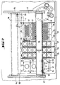
- FIG. 1 shows a perspective view of an analysis device 11.
- This device contains a horizontally arranged base plate 12 on which primary vessels, for example sample vessels 13 or reagent containers 23, and secondary vessels, for example reaction vessels 31, are arranged.
- the analysis device 11 contains an automatic pipetting device, in which a pipetting needle 42 consisting of an electrically conductive material is connected by a line 99 to a metering device 96.
- This metering device is, for example, an automatically controlled metering syringe, which is contained in the transport head 51 mentioned below.
- a predetermined volume of liquid is transferred from a primary vessel 13 or 23 to a secondary vessel 31 with the pipetting needle 42.
- the pipetting device contains a transport device 51-55 for the controlled transport of the pipetting needle 42 in three mutually perpendicular directions, X, Y, Z direction, two of the transport directions X and Y direction being horizontal and the third transport direction Z direction runs vertically.
- the transport device contains a transport head 51.
- the transport head contains a drive 52 for transporting the pipetting needle 42 in the vertical direction.
- the transport head 51 preferably also contains a drive 53 for transporting a gripper 43 in the vertical direction. With this gripper, reaction vessels can be transported to different processing positions, e.g. from a loading position, in which the reaction vessels are loaded with samples and reagents, to an incubator 36 contained in the analysis device, and from there to a washing device 62 also contained in the analysis device or to a photometer 61.
- the transport head 51 can be moved along a rail 55 in the X direction by a suitable drive.
- This rail 55 can be moved along rails 54 in the Y direction by a suitable drive (see FIG. 2).
- the rails 54 are fastened on the base plate 12.
- the analysis device contains an electrically conductive reference body 45 which is firmly connected to the base plate 12 and which has two outer surfaces 76, 77 and 78, 79 in each of the horizontal transport directions X and Y directions, respectively, which are arranged perpendicular to the transport direction are.
- the reference body 45 is used for the fine adjustment of the transport device 51-55 of the pipetting needle described below.
- the reference body 45 is preferably a square bolt with a square cross section.
- the sample containers 13 can e.g. be arranged in a circular arrangement 14 which is received in one of the sample vessel holders.
- Each of the sample vessels 13 has a lid which can be pierced with the pipetting needle.
- Each of the sample vessel holders 16, 17, 18 has a lid which has openings through which the pipetting needle has access to the lids of the sample vessels. The pipetting processes are carried out with closed sample vessels.
- each of the reagent containers 23, 24 is closed with a corresponding lid. This lid can also be pierced with the pipetting needle. The pipetting processes are carried out with closed reagent vessels.
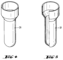
- FIG. 4 shows an enlarged perspective illustration of one of the reaction vessels 31 in FIGS. 1-3.
- FIG. 5 shows a representation of the reaction vessel 31 in FIG. 4, which shows the interior of the reaction vessel.
- All operations to be performed including the control of the dosing device 96 and the transport device 51-55 are controlled and coordinated by a central control unit (not shown) of the analysis device.
- a user interface 64 or keyboard for entering process parameters, as well as a display for displaying process states is shown schematically.
- the sample data which are applied to the sample tube by means of a barcode, for example, can be read into a memory using a manually operated stylus or scanner 63. Interfaces for a printer etc. (not shown) are provided.
- the embodiments of the analysis device 11 described below contain means for rough adjustment of the transport device 51-55 of the pipetting needle 42.
- means are used, for example, with which the pipetting needle 42 is guided to an end position and the coordinates (Xe, Ye, Ze) of the end position of the Pipette needle recorded and stored in each of the three mutually perpendicular directions become.
- the end position of the pipetting needle 42 in the X or Y direction is defined by the corresponding end position of the transport head 51. 2, the transport head 51 is shown in its end position in the X and Y directions.
- the end position of the transport head 51 in the X direction is detected by suitable means when the transport head 51 reaches the stop 56.
- the end position of the transport head 51 in the Y direction is detected by suitable means when the transport head 51 reaches the stop 57.
- the highest possible position of the pipetting needle, which enables its drive 52, defines the end position of the pipetting needle in the Z direction.
- the reaching of the end position of the transport head 51 in each transport direction is detected by suitable means, for example by an electrical signal which is triggered by the contact between the transport head 51 and a stop and which is transmitted to the control unit of the analysis device.
- the scanned region of the reference body 45 preferably has a square cross section in a plane perpendicular to the longitudinal axis of the reference body 45.
- the electrical resistance of the liquid contained in line 99, which connects pipetting needle 42 to metering system 96 (see FIG. 9), is preferably greater than a predetermined limit.
- the X and Y coordinates of all pipetting positions of the pipetting needle in relation to the coordinates of the reference position are calculated on the basis of the relevant dimensions of the different parts of the analysis device in the control unit mentioned above.
- a second preferred embodiment of the analysis device contains means for determining the coordinates Xo, Yo of a reference axis which runs parallel to the vertical transport direction Z and through the reference body 45, these means being suitable for moving the transport device 51-55 of the pipetting needle 42 in such a way that that the pipetting needle 42 is moved in both horizontal transport directions (X and Y direction) and in opposite directions to a position in the vicinity of each of the two outer surfaces 76, 77 and 78, 79 of the reference body 45, which is perpendicular to the transport direction are arranged, the pipetting needle 42 each moving toward a surface of the reference body 45 is until the value of the electrical capacitance measured with the circuit between the pipetting needle 42 and the reference body 45 reaches a predetermined value which corresponds to a certain distance between the pipetting needle 42 and the surface of the reference body 45.
- the X and Y coordinates of all pipetting positions of the pipetting needle with respect to Xo, Yo are calculated on the basis of the relevant dimensions of the different parts of the analysis device in the control unit mentioned above.
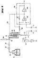
- a circuit according to FIG. 9 is used, which is also used in the analysis device as part of a level sensing device ("level detector").
- level sensing device With such a level sensing device, the immersion depth of the pipetting needle during the pipetting processes (for example when taking a sample volume from a sample vessel) is controlled by measuring the electrical capacitance between the pipetting needle and the surface of the liquid sample so that only a very short segment of the Tip of the pipetting needle penetrates into the liquid sample and thus the amount of sample undesirably carried along on the outer surface of the pipetting needle is as small as possible.
- the pipetting needle has the additional function of being a part of the electrical measuring circuit with which the electrical capacitance between the pipetting needle and the surface of the liquid sample is measured.
- the pipetting needle 42 is in liquid communication with the liquid in one through a hose 99, a connecting piece 98 and a T-link 95 with a metering syringe 96 and through a valve 94, a pump 93 and a line 92 Liquid container 91. All of these components form a liquid system which is filled with the liquid contained in the liquid container 91 during operation of the pipetting device. In the present exemplary embodiment, this liquid has good electrical conductivity.
- the hose 99 is arranged in a shielding housing 101 (“guarding case”).
- the connector 98 is mechanically and electrically connected to the shield housing 101 and to the liquid in the line 97.
- the pipetting needle 42 is electrically connected to the input of an oscillator circuit 104 through the inner conductor of a coaxial cable 103.
- the oscillator circuit 104 contains an impedance converter 105 and a voltage comparator 106 connected thereto.
- a coupling resistor R 1 connects the output of the voltage comparator 106 to the input of the impedance converter 105.
- the electrical connection of the output of the impedance converter 105 to the voltage comparator 106 is connected to the outer conductor of the coaxial cable 103 and electrically connected to the shield housing 101 and to the liquid in the line 97 via a line 102 (“guard”).
- the shielding housing 101 ("guarding case") and the line 102 (“guard”) serve to electrically decouple the circuit for measuring the capacitance C2 between the pipetting needle 42 and the reference body 45 from the above-mentioned liquid system of the pipetting device.
- the function of the circuit for measuring the capacitance C2 between the pipetting needle 42 and the reference body 45 is made insensitive to stray capacities which would otherwise influence the function of the measuring circuit by the mechanical and fluid connection of the pipetting needle 42 with the above-mentioned liquid system.
- the reference body 45 is mechanically and electrically connected directly to a base plate 12 of the analysis device (see FIG. 1).
- the base plate 12 is electrically connected to the earth.
- C2 represents the capacitance between the pipetting needle 42 and the reference body 45.
- C3 represents the capacitance between the mass of the oscillator circuit 104 and earth.
- Fig. 10 shows an equivalent circuit diagram of the arrangement according to Fig. 9.
- R2 represents the electrical resistance of the liquid in the hose 99 in Fig. 9.
- Fig. 11 shows the variation of the capacitance C2 in picofarads as a function of the distance between the pipetting needle 42 and the reference body 45th
- f can have other values. Significantly higher values of f, e.g. in the megahertz range are disadvantageous because the influence of interference signals is too great. Significantly lower values of f are also disadvantageous because more time is required to evaluate the output signal of the oscillator circuit.
- FIG. 10 shows, inter alia, the waveforms at 3 points of the equivalent circuit diagram of the oscillator circuit 104 according to FIG. 9 shown there.
- the value of C2 increases according to FIG. 11, and this leads to a corresponding change in the value of f.
- the value of C2 is previously measured for a specific position of the pipetting needle 42 in the analyzer 11. This particular position of the pipetting needle is, for example, the position 71 shown in FIGS. 6 and 7, in which the distance S 1 between the pipetting needle 42 and the reference body 45 is three millimeters.
- the corresponding value of C2 is designated in Fig. 11 with C71.
- the resistance R2 of the liquid in the hose 99 does not fall below a limit of 100 kilohms. Otherwise R2 would overload the impedance converter 105 too much.
- a too low value of R2 can result from the fact that the liquid in the liquid system of the pipetting device has a very low specific electrical resistance.
- the pipetting needle 42 of the automatic pipetting device of the analysis device 11 is guided to a number of pipetting positions by means of a transport device 51-55, each pipetting position corresponding to the position of a particular vessel, the transport device 51-55 being set up to dispense the pipetting needle 42 in three mutually perpendicular directions (X, Y, Z directions), and each of these directions is parallel to one of the coordinate axes of the coordinate system of the transport device 51-55.
- a rough adjustment of the transport device 51-55 of the pipetting needle 42 is carried out.
- the pipetting needle 42 is guided with the transport device 51-55 to the end position defined above in each of the three directions perpendicular to one another and the coordinates (X e , Y e , Z e ) of the end position are recorded and stored.
- the electrically conductive reference body 45 is used, which is firmly connected to the base plate 12 and which has two outer surfaces 76, 77 and 78, 79 in each of the horizontal transport directions (X and Y directions), which are perpendicular to Transport direction are arranged.
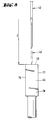
- the pipetting needle is preferably in the vertical position shown in FIG. 7 (ie in the Z direction) during its guided movement against one of the lateral outer surfaces of the reference body 45, in which a considerable part of the Pipetting needle is opposite the outer surface. In this way it is achieved that the capacity C2 has a sufficiently high value.
- the vertical position of the pipetting needle according to FIG. 7 just mentioned ensures that the accuracy of the adjustment is very high, in particular for the upper part of the pipetting needle, i.e. the upper part of the pipetting needle is positioned at the various pipetting positions with the greatest accuracy. In the present exemplary embodiment, this has the additional advantage that the gripper 43 carried or guided by the transport head 51 is also positioned with great accuracy at the various positions where it grips or brings the reaction vessels 31.
- a reference position in the Z direction is defined in which the pipetting needle 42 is moved from its starting position in the highest position and with decreasing speed towards the center of the upper surface 46 of the reference body 45 until the tip of the pipetting needle touches the surface 46 and this contact is detected with a suitable circuit.
- the the reference position of the pipetting needle in the Z direction thus determined is stored.
- the coordinate values of the two positions of the pipetting needle 42 thus defined are also recorded and stored in the at least one horizontal transport direction.
- the coordinate values of a reference position are determined in the at least one horizontal transport direction.
- the X and Y coordinates of all pipetting positions of the pipetting needle in relation to the coordinates of the reference position are calculated on the basis of the relevant dimensions of the different parts of the analysis device in the control unit mentioned above.
- the coordinates Xo, Yo of a reference axis are determined which run parallel to the vertical transport direction (Z) and through the reference body 45.
- the pipetting needle 42 is moved by means of the transport device 51-55 in both horizontal transport directions (X and Y direction) to a position in the vicinity of each of the two outer surfaces 76, 77 and 78, 79 of the reference body 45, which is vertical are arranged to the transport direction, the pipetting needle 42 in each case to a surface of the reference body 45 is moved until the measured value of the electrical capacitance between the pipetting needle 42 and the reference body 45 reaches a predetermined value, which corresponds to a certain distance between the pipetting needle 42 and the surface of the reference body 45.
- the same method is carried out in the X direction.
- the pipetting needle is first moved towards a surface 78 of the reference body 45 until the measured value of the electrical capacitance between the pipetting needle 42 and the reference body 45 reaches a predetermined value C 74, which corresponds to a certain distance S 74 between the pipetting needle 42 and the Surface of the reference body 45 corresponds, this process is then carried out in the opposite direction, ie the pipetting needle 42 is moved in the Y direction to a surface 79 of the reference body 45 until the measured value of the electrical capacitance between the pipetting needle 42 and the reference body 45 reaches a predetermined value C 75, which corresponds to a certain distance S 75 between the pipetting needle 42 and the surface of the reference body 45.
- the coordinate values of the two positions of the pipetting needle 42 thus defined are preferably recorded and stored in each of the horizontal transport directions.
- the coordinate values of a reference position in each of the horizontal transport directions are determined by calculating the mean value of the two recorded coordinate values.
- the X and Y coordinates of all pipetting positions of the pipetting needle with respect to Xo, Yo are calculated on the basis of the relevant dimensions of the different parts of the analysis device in the control unit mentioned above.
Abstract
Description
Die Erfindung betrifft ein Analysengerät, das folgende Komponenten enthält:
- eine waagerecht angeordnete Grundplatte auf der Primärgefässe und Sekundärgefässe angeordnet sind,
- eine mit einer Dosiervorrichtung verbundenen, aus einem elektrisch leitenden Material bestehenden Pipettiernadel zur Uebertragung von jeweils einem vorbestimmten Flüssigkeitsvolumen von einem Primärgefäss zu einem Sekundärgefässe,
- eine Transportvorrichtung zum gesteuerten Transport der Pipettiernadel in drei zueinander senkrechten Richtungen (X-, Y-, Z-Richtung) , wobei zwei der Transportrichtungen (X- bzw. Y-Richtung) waagerecht verlaufen und die dritte Transportrichtung (Z) vertikal verläuft,
- einen mit der Grundplatte fest verbundenen, elektrisch leitenden Bezugskörper, der in jeder der waagerechten Transportrichtungen (X- bzw. Y-Richtung) zwei Aussenflächen hat, die senkrecht zur Transportrichtung angeordnet sind,
- eine Steuereinrichtung zur Steuerung der Dosiervorrichtung und der Transportvorrichtung.
- a horizontally arranged base plate on which primary vessels and secondary vessels are arranged,
- a pipetting needle, which is connected to a metering device and consists of an electrically conductive material, for transferring a predetermined volume of liquid in each case from a primary vessel to a secondary vessel,
- a transport device for the controlled transport of the pipetting needle in three mutually perpendicular directions (X, Y, Z direction), two of the transport directions (X or Y direction) running horizontally and the third transport direction (Z) running vertically,
- an electrically conductive reference body which is firmly connected to the base plate and has two outer surfaces in each of the horizontal transport directions (X or Y direction), which are arranged perpendicular to the transport direction,
- a control device for controlling the metering device and the transport device.
Die Erfindung betrifft insbesondere die Ausgestaltung der Transportvorrichtung der Pipettiernadel der Pipettiervorrichtung eines automatischen Analysengerätes ist, z.B. ein Analysengerät zur Durchführung von Analysen biologischer Proben.The invention relates in particular to the design of the transport device of the pipetting needle of the pipetting device of an automatic analysis device, for example an analysis device for carrying out analyzes of biological samples.
Die Erfindung betrifft ferner ein Verfahren zum automatischen Transport einer Pipettiernadel einer automatischen Pipettiervorrichtung eines Analysengerätes zu einer Anzahl Pipettierpositionen mittels einer Transportvorrichtung, wobei jede Pipettierposition der Position eines bestimmten Gefässes entspricht, das auf einer Gefässträgereinheit angeordnet ist, wobei die Transportvorrichtung dazu eingerichtet ist, die Pipettiernadel in drei zueinander senkrechten Richtungen (X, Y, Z) zu bewegen, und wobei jede dieser Richtungen parallel zu einer der Koordinatenachsen des Koordinatensystems der Transportvorrichtung ist, wobei zur Messung der Koordinaten von Bezugspunkten ein elektrisch leitenden Bezugskörper verwendet wird, der mit der Grundplatte fest verbunden ist, und der in jeder der waagerechten Transportrichtungen (X-bzw. Y-Richtung) zwei Aussenflächen hat, die senkrecht zur Transportrichtung angeordnet sind.The invention further relates to a method for the automatic transport of a pipetting needle of an automatic pipetting device of an analytical device to a number of pipetting positions by means of a transport device, each pipetting position corresponding to the position of a specific vessel which is arranged on a vessel carrier unit, the transport device being set up for the pipetting needle in three mutually perpendicular directions (X, Y, Z), and each of these directions is parallel to one of the coordinate axes of the coordinate system of the transport device, an electrically conductive reference body being used to measure the coordinates of reference points, which is fixed to the base plate is connected, and which has two outer surfaces in each of the horizontal transport directions (X or Y direction), which are arranged perpendicular to the transport direction.
Ein typischer Pipettiervorgang in einem automatischen Analysengerät ist z.B. die Entnahme eines bestimmten Reagenzvolumens aus einem Primärgefäss, z.B. einem Reagenzbehälter, und dessen Abgabe an einem Sekundärgefäss, z.B. einem Reaktionsgefäss. Dabei führt eine Transportvorrichtung die Pipettiernadel von einer Zielposition zur nächsten. In jeder Zielposition bewirkt die automatisch gesteuerte Dosiervorrichtung die gewünschte Entnahme oder Abgabe eines Flüssigkeitsvolumens.A typical pipetting process in an automatic analyzer is e.g. the removal of a certain volume of reagent from a primary vessel, e.g. a reagent container, and its delivery to a secondary vessel, e.g. a reaction vessel. A transport device guides the pipetting needle from one target position to the next. In every target position, the automatically controlled dosing device effects the desired withdrawal or delivery of a volume of liquid.
Im dreidimensionalen, rechtwinkligen Koordinatensystem der Transportvorrichtung sind die Primär- bzw. Sekundärgefässe in Gefässbehälter auf Trägerplatten angeordnet, die parallel zur XY- Ebene des Koordinatensystems sind. Wenn die Transportvorrichtung die Pipettiernadel zu einer Zielposition führt, bewegt diese Vorrichtung die Pipettiernadel zunächst in einer zur XY-Ebene parallelen Ebene bis sie oberhalb des Zielgefässes liegt und bewirkt anschliessend eine Abwärtsbewegung der Pipettiernadel bis diese in der richtigen Lage für eine Flüssigkeitsentnahme aus einem Primärgefäss bzw. eine Flüssigkeitsabgabe in ein Sekundärgefäss befindet.In the three-dimensional, right-angled coordinate system of the transport device, the primary or secondary vessels are arranged in vessel containers on support plates which are parallel to the XY plane of the coordinate system. When the transport device leads the pipetting needle to a target position, this device first moves the pipetting needle in a plane parallel to the XY plane until it lies above the target vessel and then causes the pipetting needle to move downwards until it is in the correct position for liquid withdrawal from a primary vessel or there is a liquid discharge in a secondary vessel.
Damit die Transportvorrichtung die Pipettiernadel zu einer genau richtigen Zielposition in der XY-Ebene, d.h. genau oberhalb eines Primär-bzw. Sekundärgefässes, führen kann, müssen folgende Bedingungen erfüllt sein:
- die Steuereinrichtung der Transportvorrichtung muss die X- und Y-Koordinaten der Zielposition als Eingangssignal erhalten, um die Transportvorrichtung entsprechend steuern zu können,
- das Primär- bzw. Sekundärgefäss muss sich an der genau richtigen Stelle befinden,
- die Transportvorrichtung muss in jeder Transportrichtung justiert sein, d.h. in jeder Transportrichtung muss eine Position definiert werden, die als Bezugsposition gilt.
- the control device of the transport device must receive the X and Y coordinates of the target position as an input signal in order to be able to control the transport device accordingly,
- the primary or secondary vessel must be in the right place,
- the transport device must be adjusted in every transport direction, ie a position must be defined in each transport direction that is to be used as the reference position.
Die Internationale Patentanmeldung mit Publikationsnummer WO 91/16675 beschreibt eine automatische Pipettiervorrichtung der eingangs erwähnten Art, bei der zur Ermittlung von Bezugswerten der Koordinaten in jeder der Bewegungsrichtungen (X-, Y-, Z-Richtung) der Pipettiernadel eine Abtastung von einer Fläche eines elektrisch leitenden Bezugskörpers mit der elektrisch leitenden Pipettiernadel durchgeführt wird, wobei der elektrische Kontakt bei der Berührung der Fläche des Bezugskörpers mit der Pipettiernadel mittels einer elektrischen Schaltung erfasst wird.The international patent application with
Die bekannte Vorrichtung hat den Nachteil, dass die wiederholte Berührung der Flächen des Bezugskörpers mit der manchmal unsauberen Aussenwand der Pipettiernadel die Entstehung von Ablagerungen auf den abgetasteten Stellen der Flächen des Bezugskörpers fordert. Je nach der Art der pipettierten Flüssigkeiten können diese Ablagerungen elektrisch leitend oder nicht leitend sein.The known device has the disadvantage that the repeated contact of the surfaces of the reference body with the sometimes unclean outer wall of the pipetting needle requires the formation of deposits on the scanned areas of the surfaces of the reference body. Depending on the type of liquids pipetted, these deposits can be electrically conductive or non-conductive.
Wenn derartige Ablagerungen elektrisch leitend sind, verursachen sie eine ungenaue Erfassung der Position der abgetasteten Flächen. Dadurch wird die Genauigkeit der Ermittlung von Bezugswerten von Koordinaten für die genaue Steuerung des Transports der Pipettiernadel in Frage gestellt.If such deposits are electrically conductive, they cause inaccurate detection of the position of the scanned areas. As a result, the accuracy of the determination of reference values of coordinates for the precise control of the transport of the pipetting needle is questioned.
Wenn derartige Ablagerungen elektrisch nicht leitend sind, verhindern sie den beabsichtigten elektrischen Kontakt zwischen Pipettiernadel und Bezugskörper. In diesem Fall wird die Pipettiernadel auch nach Erreichen der abgetasteten Fläche wegen ausbleibender Kontakterfassung von der Transportvorrichtung gegen den Bezugskörper gedrückt. Die entsprechende mechanische Belastung kann die Pipettiernadel verbiegen und sie auf diese Weise unbrauchbar machen.If such deposits are electrically non-conductive, they prevent the intended electrical contact between the pipetting needle and the reference body. In this case, the pipetting needle is pressed by the transport device against the reference body even after reaching the scanned area due to the lack of contact detection. The corresponding mechanical load can bend the pipetting needle and in this way render it unusable.
Der Erfindung liegt daher die Aufgabe zugrunde, ein Analysengerät zur Verfügung zu stellen, das die oben erwähnten Nachteile nicht hat. Der Erfindung liegt ferner die Aufgabe zugrunde, ein Verfahren zum automatischen Transport der Pipettiernadel einer automatischen Pipettiervorrichtung der eingangs angegebenen Art zur Verfügung zustellen, mit der das soeben definierte Ziel erreichbar ist.The invention is therefore based on the object of providing an analysis device which does not have the disadvantages mentioned above. The invention is also based on the object of providing a method for automatically transporting the pipetting needle to an automatic pipetting device of the type specified at the outset, with which the target just defined can be reached.
Der erste Teil der obigen Aufgabe wird erfindungsgemäss mit einem Analysengerät der eingangs erwähnten Art gelöst, das dadurch gekennzeichnet ist, dass es folgende Mittel enthält:
eine Schaltung zur Messung der elektrischen Kapazität zwischen der Pipettiernadel und dem Bezugskörper und
Mittel zur Bestimmung der Koordinaten einer Bezugsposition der Pipettiernadel in wenigstens einer der waagerechten Transportrichtungen (X- bzw. Y-Richtung), wobei diese Mittel dazu geeignet sind, die Transportvorrichtung der Pipettiernadel so zu bewegen, dass die Pipettiernadel zu einer Position in der Nähe jeder der beiden Aussenflächen des Bezugskörpers bewegt wird, die senkrecht zur Transportrichtung angeordnet sind, wobei die Pipettiernadel jeweils zu einer Fläche des Bezugskörpers hin bewegt wird, bis die elektrische Kapazität zwischen der Pipettiernadel und dem Bezugskörper einen vorbestimmten Wert erreicht, der einem bestimmten Abstand zwischen der Pipettiernadel und der Fläche des Bezugskörpers entspricht.The first part of the above object is achieved according to the invention with an analysis device of the type mentioned at the outset, which is characterized in that it contains the following means:
a circuit for measuring the electrical capacitance between the pipetting needle and the reference body and
Means for determining the coordinates of a reference position of the pipetting needle in at least one of the horizontal transport directions (X or Y direction), these means being suitable for moving the transport device of the pipetting needle so that the pipetting needle is in a position in the vicinity of each of the two outer surfaces of the reference body, which are arranged perpendicular to the transport direction, the pipetting needle being moved in each case towards a surface of the reference body until the electrical capacitance between the pipetting needle and the reference body reaches a predetermined value which corresponds to a certain distance between the pipetting needle and corresponds to the surface of the reference body.
Der zweite Teil der obigen Aufgabe wird erfindungsgemäss mit einem Verfahren der eingangs erwähnten Art gelöst, das dadurch gekennzeichnet ist, dass
die elektrische Kapazität zwischen der Pipettiernadel und dem Bezugskörper gemessen wird, und
zur Bestimmung der Koordinaten einer Bezugsposition der Pipettiernadel in wenigstens einer der waagerechten Transportrichtungen (X- bzw. Y-Richtung), wird die Pipettiernadel mit der Transportvorrichtung in entgegengesetzten Richtungen zu je einer Position in der Nähe jeder der beiden Aussenflächen des Bezugskörpers bewegt wird, die senkrecht zur Transportrichtung angeordnet sind, wobei die Pipettiernadel jeweils zu einer Fläche des Bezugskörpers hin bewegt wird, bis der gemessene Wert der elektrischen Kapazität zwischen der Pipettiernadel und dem Bezugskörper einen vorbestimmten Wert erreicht, der einem bestimmten Abstand zwischen der Pipettiernadel und der Fläche des Bezugskörpers entspricht.The second part of the above object is achieved according to the invention with a method of the type mentioned at the outset, which is characterized in that
the electrical capacitance between the pipetting needle and the reference body is measured, and
To determine the coordinates of a reference position of the pipetting needle in at least one of the horizontal transport directions (X or Y direction), the pipetting needle is moved with the transport device in opposite directions to a position in the vicinity of each of the two outer surfaces of the reference body, which are arranged perpendicular to the direction of transport, the pipetting needle being moved in each case towards a surface of the reference body until the measured value of the electrical capacitance between the pipetting needle and the Reference body reaches a predetermined value, which corresponds to a certain distance between the pipetting needle and the surface of the reference body.
Der Hauptvorteil des erfindungsgemässen Analysengerätes bzw. des erfindungsgemässen Verfahrens liegt darin, dass für die beabsichtigte Funktion der erfindungsgemässen Vorrichtung eine Berührung der abgetasteten Flächen mit der Pipettiernadel nicht erforderlich ist, d.h. die Abtastung der Flächen ist berührungslos. Mit der erfindungsgemässen Lösung können sich daher praktisch keine Ablagerungen auf den abgetasteten Flächen des Bezugskörpers bilden. Derartige Ablagerungen können daher in keiner Weise die Genauigkeit und Zuverlässigkeit des erfindungsgemässen Verfahrens beeinträchtigen oder Deformationen der Pipettiernadel verursachen.The main advantage of the analysis device according to the invention and the method according to the invention is that the intended function of the device according to the invention does not require the scanned surfaces to come into contact with the pipetting needle, i.e. the scanning of the surfaces is contactless. With the solution according to the invention, therefore, practically no deposits can form on the scanned surfaces of the reference body. Such deposits can therefore in no way impair the accuracy and reliability of the method according to the invention or cause deformations of the pipetting needle.
Ein weiterer Vorteil des erfindungsgemässen Analysengerätes bzw. des erfindungsgemässen Verfahrens liegt darin, dass eine korrekte und zuverlässige Funktion der erfindungsgemässen Vorrichtung ist auch dann gewährleistet, wenn das Pipettiersystem mit einer elektrisch leitenden Flüssigkeit gefüllt ist.Another advantage of the analysis device according to the invention and the method according to the invention is that correct and reliable functioning of the device according to the invention is ensured even when the pipetting system is filled with an electrically conductive liquid.
Eine bevorzugte Ausführungsform des erfindungsgemässen Analysengerätes ist dadurch gekennzeichnet, dass der elektrische Widerstand der Flüssigkeit, die in der Leitung enthalten ist, die die Pipettiernadel mit dem Dosiersystem verbindet, grösser als einen vorbestimmten Grenzwert ist. Dies wird durch geeignete Wahl der Abmessungen (Durchmesser, Länge) der Leitung, die die Pipettiernadel mit dem Dosiersystem verbindet. Diese Ausführungsform hat den Vorteil, dass mögliche Störungen, die auf die elektrische Leitfähigkeit der Flüssigkeit im Pipettiersystem in Kombination mit gerätespezifischen Abweichungen in der elektrischen Umgebung der Pipettiernadel zurückzuführen sind, keinen Einfluss auf die Funktion des erfindungsgemässen Analysengerätes haben können.A preferred embodiment of the analytical device according to the invention is characterized in that the electrical resistance of the liquid contained in the line connecting the pipetting needle to the dosing system is greater than a predetermined limit value. This is made possible by a suitable choice of the dimensions (diameter, length) of the line which connects the pipetting needle to the dosing system. This embodiment has the advantage that possible disturbances which are due to the electrical conductivity of the liquid in the pipetting system in combination with device-specific deviations in the electrical environment of the pipetting needle cannot have any influence on the function of the analysis device according to the invention.
Ein Ausführungsbeispiel der Erfindung wird im folgenden anhand der beiliegenden Zeichnungen beschrieben. Es zeigen:
- Fig. 1 eine perspektivische Ansicht eines Analysengerätes.
- Fig. 2 eine Draufsicht des in Fig. 1 dargestellten Analysengerätes.
- Fig. 3 eine perspektivische schematische Darstellung der Anordnung der Probegefässe, Reagenzgefässe und Reaktionsgefässe im
Analysengerät 11. - Fig. 4 eine vergrösserte perspektivische Darstellung eines der
Reaktionsgefässe 31 in Figuren 1-3. - Fig. 5 eine Darstellung des
Reaktionsgefässe 31 in Fig. 4, die den Innenraum desReaktionsgefässes 31 zeigt. - Fig. 6 eine schematische Darstellung einer Abtastung eines
Bezugskörpers 45 mit einerPipettiernadel 42. - Fig. 7 eine schematische Darstellung der Bewegung der
Pipettiernadel 42 in einer waagerechten Richtung (X- bzw. Y- Richtung) beim Abtastvorgang gemäss Fig. 6. - Fig. 8 eine schematische Darstellung einer Abtastung in vertikaler Richtung (Z-Richtung) der oberen Fläche eines
Bezugskörpers 45 mit einerPipettiernadel 42. - Fig. 9 eine schematische Darstellung einer Anordnung zur Messung der Kapazität zwischen der
Pipettiernadel 42 und demBezugskörper 45. - Fig. 10 ein Ersatzschaltbild der Anordnung gemäss Fig. 9.
- Fig. 11 ein Diagramm der Variation der elektrischen Kapazität zwischen der
Pipettiernadel 42 und demBezugskörper 45.
- Fig. 1 is a perspective view of an analyzer.
- Fig. 2 is a plan view of the analyzer shown in Fig. 1.
- 3 shows a perspective schematic illustration of the arrangement of the sample vessels, reagent vessels and reaction vessels in the
analysis device 11. - 4 shows an enlarged perspective view of one of the
reaction vessels 31 in FIGS. 1-3. - FIG. 5 shows the
reaction vessel 31 in FIG. 4, which shows the interior of thereaction vessel 31. - 6 shows a schematic illustration of a scanning of a
reference body 45 with apipetting needle 42. - 7 shows a schematic illustration of the movement of the
pipetting needle 42 in a horizontal direction (X or Y direction) during the scanning process according to FIG. 6. - 8 shows a schematic illustration of a scanning in the vertical direction (Z direction) of the upper surface of a
reference body 45 with apipetting needle 42. - 9 shows a schematic illustration of an arrangement for measuring the capacitance between the pipetting
needle 42 and thereference body 45. - 10 shows an equivalent circuit diagram of the arrangement according to FIG. 9.
- 11 shows a diagram of the variation of the electrical capacitance between the pipetting
needle 42 and thereference body 45.
Fig. 1 zeigt eine perspektivische Ansicht eines Analysengerätes 11. Dieses Gerät enthält eine waagerecht angeordnete Grundplatte 12 auf der Primärgefässe, z.B. Probengefässe 13 bzw. Reagenzbehälter 23, und Sekundärgefässe, z.B. Reaktionsgefässe 31 angeordnet sind. Das Analysengerät 11 enthält eine automatische Pipettiereinrichtung, in der eine aus einem elektrisch leitenden Material bestehenden Pipettiernadel 42 durch eine Leitung 99 mit einer Dosiervorrichtung 96 verbunden ist. Diese Dosiervorrichtung ist z.B. eine automatisch gesteuerte Dosierspritze, die im nachstehend erwähnten Transportkopf 51 enthalten ist.1 shows a perspective view of an
Mit der Pipettiernadel 42 wird jeweils ein vorbestimmtes Flüssigkeitsvolumen von einem Primärgefäss 13 bzw. 23 zu einem Sekundärgefäss 31 übertragen. Die Pipettiereinrichtung enthält eine Transportvorrichtung 51-55 zum gesteuerten Transport der Pipettiernadel 42 in drei zueinander senkrechten Richtungen, X- ,Y- , Z-Richtung, wobei zwei der Transportrichtungen X- bzw. Y-Richtung waagerecht verlaufen und die dritte Transportrichtung Z-Richtung vertikal verläuft. Die Transportvorrichtung enthält einen Transportkopf 51. Der Transportkopf enthält einen Antrieb 52 zum Transport der Pipettiernadel 42 in vertikaler Richtung. Vorzugsweise enthält der Transportkopf 51 ausserdem einen Antrieb 53 zum Transport eines Greifers 43 in vertikaler Richtung. Mit diesem Greifer können Reaktionsgefässe zu verschiedenen Bearbeitungspositionen transportiert werden, z.B. von einer Ladeposition, bei der die Reaktionsgefässe mit Proben und Reagenzien beschickt werden, zu einem im Analysengerät enthaltenen Inkubator 36, und von dort zu einer ebenfalls im Analysengerät enthaltenen Wascheinrichtung 62 oder zu einem Photometer 61.A predetermined volume of liquid is transferred from a
Der Transportkopf 51 ist durch einen geeigneten Antrieb in X-Richtung entlang einer Schiene 55 bewegbar. Diese Schiene 55 ist durch einen geeigneten Antrieb in Y-Richtung entlang Schienen 54 bewegbar (siehe Fig. 2). Die Schienen 54 sind auf der Grundplatte 12 befestigt.The
Das Analysengerät enthält einen elektrisch leitenden Bezugskörper 45, der mit der Grundplatte 12 fest verbunden ist, und der in jeder der waagerechten Transportrichtungen X- bzw. Y-Richtung je zwei Aussenflächen 76, 77 bzw. 78, 79 hat, die senkrecht zur Transportrichtung angeordnet sind. Der Bezugskörper 45 wird für die nachstehend beschriebene feine Justierung der Transportvorrichtung 51-55 der Pipettiernadel verwendet. Der Bezugskörper 45 ist vorzugsweise ein Vierkantbolzen mit einem quadratischen Querschnitt.The analysis device contains an electrically
Auf der Grundplatte 12 ist eine Trägerplatte 21 angeordnet. Auf diese Trägerplatte werden verschiedene Gefässe angeordnet. Wie in Fig. 1-3 dargestellt, sind z.B. auf Trägerplatte 21 folgende Gefässe angeordnet:
Probengefässe 13 inProbengefässhalter einer Probengefässhaltereinheit 15 angeordnet sind,Reagenzgefässe Reagenzgefässhalter Reaktionsgefässe 31 inReaktionsgefässhalter
-
Sample vessels 13 insample vessel holders vessel holder unit 15, -
Reagent tubes reagent tube holders -
Reaction vessels 31 inreaction vessel holders
Wie in Fig. 3 gezeigt, können die Probenbehälter 13 z.B. in einer kreisförmigen Anordnung 14 angeordnet sein, die in einem der Probengefässhalter aufgenommen wird. Jedes der Probengefässe 13 hat einen Deckel, der mit der Pipettiernadel durchstechbar ist. Jeder der Probengefässhalter 16, 17, 18 hat einen Deckel, der Oeffnungen aufweist, durch die die Pipettiernadel Zugang zu den Deckeln der Probengefässe hat. Die Pipettiervorgänge werden mit verschlossenen Probengefässe durchgeführt.As shown in Fig. 3, the
Wie aus Fig. 3 ersichtlich ist jeder der Reagenzbehälter 23, 24 mit einem entsprechenden Deckel geschlossen. Auch dieser Deckel ist mit der Pipettiernadel durchstechbar. Die Pipettiervorgänge werden mit verschlossenen Reagenzgefässe durchgeführt.3, each of the
Fig. 4 zeigt eine vergrösserte perspektivische Darstellung eines der Reaktionsgefässe 31 in Figuren 1-3. Fig. 5 zeigt eine Darstellung des Reaktionsgefässes 31 in Fig. 4, die den Innenraum des Reaktionsgefässes zeigt.FIG. 4 shows an enlarged perspective illustration of one of the
Sämtliche durchzuführende Operationen, u.a. die Steuerung der Dosiervorrichtung 96 und der Transportvorrichtung 51-55 sind durch eine zentrale Steuereinheit (nicht dargestellt) des Analysengeräts gesteuert und koordiniert. Eine Bedienoberfläche 64 bzw. Tastatur zur Eingabe von Prozessparametern, sowie eine Anzeige zur Anzeige von Prozesszuständen ist schematisch dargestellt. Die Probendaten, welche beispielsweise mittels Barcode auf den Proberöhrchen aufgebracht sind, können über einen manuell geführten Lesegriffel oder Scanner 63 in einen Speicher eingelesen werden. Schnittstellen für einen Printer usw. (nicht dargestellt) sind vorgesehen.All operations to be performed, including the control of the
Die nachstehend beschriebenen Ausführungsformen des Analysengerätes 11 enthalten Mittel zur groben Justierung der Transportvorrichtung 51-55 der Pipettiernadel 42. Hierfür werden z.B. Mittel verwendet, mit denen die Pipettiernadel 42 zu einer Endposition geführt wird und die Koordinaten (Xe , Ye, Ze) der Endposition der Pipettiernadel in jeder der drei zueinander senkrechten Richtungen erfasst und gespeichert werden. Die Endposition der Pipettiernadel 42 in X- bzw. Y-Richtung ist durch die entsprechende Endposition des Transportkopfes 51 definiert. In Fig. 2 wird der Transportkopf 51 in seiner Endposition in X- und Y-Richtung gezeigt. Die Endposition des Transportkopfes 51 in X- Richtung wird durch geignete Mittel erfasst, wenn der Transportkopf 51 den Anschlag 56 erreicht. Die Endposition des Transportkopfes 51 in Y-Richtung wird durch geignete Mittel erfasst, wenn der Transportkopf 51 den Anschlag 57 erreicht. Die höchst mögliche Lage der Pipettiernadel, die deren Antrieb 52 ermöglicht, definiert die Endposition der Pipettiernadel in Z-Richtung. Die Erreichung der Endposition des Transportkopfs 51 in jeder Transportrichtung wird durch geeignete Mittel erfasst, z.B. durch ein elektrisches Signal, das durch den Kontakt zwischen dem Transportkopf 51 und einem Anschlag ausgelöst und das an die Steuereinheit des Analysengerätes übermittelt wird.The embodiments of the
In Fig. 2 wird durch gestrichelte Linien die Grundstellung 58 des Transportkopfes 51 in X-Richtung und die Grundstellung 59 der Schiene 55 in Y-Richtung dargestellt.2, the
Das Analysengerät 11 enthält ferner folgende Mittel zur feinen, d.h. sehr genauen Justierung der Transportvorrichtung 51-55:
- eine Schaltung zur Messung der elektrischen Kapazität zwischen der Pipettiernadel 42
und dem Bezugskörper 45, und - Mittel zur Bestimmung der Koordinaten einer Bezugsposition der Pipettiernadel 42 in wenigstens einer der waagerechten Transportrichtungen X- bzw. Y-Richtung, wobei diese Mittel dazu geeignet sind, die Transportvorrichtung 51-55
der Pipettiernadel 42 so zu bewegen, dass diePipettiernadel 42 in entgegengesetzten Richtungen zu je einer Position in der Nähe jeder der beiden Aussenflächen 76, 77 bzw. 78, 79 desBezugskörpers 45 bewegt wird, die senkrecht zur Transportrichtung angeordnet sind,wobei die Pipettiernadel 42 jeweils zu einer Fläche des Bezugskörpers 45 hin bewegt wird, bis der mit der Schaltung gemessene Wert der elektrischen Kapazität zwischen der Pipettiernadel 42und dem Bezugskörper 45 einen vorbestimmten Wert erreicht, der einem bestimmten Abstand zwischen der Pipettiernadel 42 und der Fläche des Bezugskörpers 45 entspricht.
- a circuit for measuring the electrical capacitance between the pipetting
needle 42 and thereference body 45, and - Means for determining the coordinates of a reference position of the
pipetting needle 42 in at least one of the horizontal transport directions X or Y direction, these means being suitable for moving the transport device 51-55 of thepipetting needle 42 such that thepipetting needle 42 is in opposite directions is moved to a position in the vicinity of each of the twoouter surfaces reference body 45, which are arranged perpendicular to the direction of transport, the pipettingneedle 42 being moved toward a surface of thereference body 45 until the with of the circuit measured value of the electrical capacitance between the pipettingneedle 42 and thereference body 45 reaches a predetermined value, which corresponds to a certain distance between the pipettingneedle 42 and the surface of thereference body 45.
Wie in Fig. 6 dargestellt, hat der abgetastete Bereich des Bezugskörpers 45 in einer zur Längsachse des Bezugskörpers 45 senkrechten Ebene vorzugsweise einen quadratischen Querschnitt.As shown in FIG. 6, the scanned region of the
Der elektrische Widerstand der Flüssigkeit, die in der Leitung 99 enthalten ist, die die Pipettiernadel 42 mit dem Dosiersystem 96 verbindet (siehe Fig. 9), ist vorzugsweise grösser als einen vorbestimmten Grenzwert ist.The electrical resistance of the liquid contained in
Eine erste bevorzugte Ausführungsform des Analysengeräts enthält ferner folgende Mittel:
- Mittel zur Erfassung und Speicherung der Koordinatenwerte der zwei so definierten Positionen der Pipettiernadel 42 in der wenigstens einer waagerechten Transportrichtung X- bzw. Y-Richtung, und
- Mittel zur Ermittlung der Koordinaten einer Bezugsposition in der Transportrichtung durch Berechnung des Mittelwertes der zwei erfassten Koordinatenwerte ermittelt wird.
- Means for acquiring and storing the coordinate values of the two positions of the
pipetting needle 42 thus defined in the at least one horizontal transport direction X and Y direction, and - Means for determining the coordinates of a reference position in the transport direction are determined by calculating the average of the two detected coordinate values.
Nach der Bestimmung der Koordinaten der Bezugsposition werden die X- bzw. Y-Koordinaten aller Pipettierpositionen der Pipettiernadel in Bezug auf die Koordinaten der Bezugsposition anhand der relevanten Dimensionen der verschiedenen Teile des Analysengerätes in der oben erwähnten Steuereinheit errechnet.After determining the coordinates of the reference position, the X and Y coordinates of all pipetting positions of the pipetting needle in relation to the coordinates of the reference position are calculated on the basis of the relevant dimensions of the different parts of the analysis device in the control unit mentioned above.
Eine zweite bevorzugte Ausführungsform des Analysengeräts enthält Mittel zur Bestimmung der Koordinaten Xo, Yo einer Bezugsachse, die parallel zur vertikalen Transportrichtung Z und durch den Bezugskörper 45 verläuft, wobei diese Mittel dazu geeignet sind, die Transportvorrichtung 51-55 der Pipettiernadel 42 so zu bewegen, dass die Pipettiernadel 42 in beiden waagerechten Transportrichtungen (X- bzw. Y-Richtung) und in entgegengesetzten Richtungen zu je einer Position in der Nähe jeder der beiden Aussenflächen 76, 77 bzw. 78, 79 des Bezugskörpers 45 bewegt wird, die senkrecht zur Transportrichtung angeordnet sind, wobei die Pipettiernadel 42 jeweils zu einer Fläche des Bezugskörpers 45 hin bewegt wird, bis der mit der Schaltung gemessene Wert der elektrischen Kapazität zwischen der Pipettiernadel 42 und dem Bezugskörper 45 einen vorbestimmten Wert erreicht, der einem bestimmten Abstand zwischen Pipettiernadel 42 und der Fläche des Bezugskörpers 45 entspricht.A second preferred embodiment of the analysis device contains means for determining the coordinates Xo, Yo of a reference axis which runs parallel to the vertical transport direction Z and through the
Nach der Bestimmung der Koordinaten Xo, Yo der oben erwähnten Bezugsachse werden die X- bzw. Y-Koordinaten aller Pipettierpositionen der Pipettiernadel in Bezug auf Xo, Yo anhand der relevanten Dimensionen der verschiedenen Teile des Analysengerätes in der oben erwähnten Steuereinheit errechnet.After determining the coordinates Xo, Yo of the reference axis mentioned above, the X and Y coordinates of all pipetting positions of the pipetting needle with respect to Xo, Yo are calculated on the basis of the relevant dimensions of the different parts of the analysis device in the control unit mentioned above.
Diese zweite bevorzugte Ausführungsform enthält vorzugsweise zusätzlich folgende Mittel:
- Mittel zur Erfassung und Speicherung der Koordinatenwerte der zwei so definierten Positionen der Pipettiernadel 42 in jeder der waagerechten Transportrichtungen (X- bzw. Y-Richtung), und
- Mittel zur Ermittlung der Koordinatenwerte einer Bezugsposition in jeder der waagerechten Transportrichtungen (X- bzw. Y-Richtung) durch Berechnung des Mittelwertes der zwei erfassten Koordinatenwerte ermittelt wird.
- Means for acquiring and storing the coordinate values of the two positions of the
pipetting needle 42 thus defined in each of the horizontal transport directions (X or Y direction), and - Means for determining the coordinate values of a reference position in each of the horizontal transport directions (X or Y direction) are determined by calculating the mean value of the two recorded coordinate values.
Zur Messung der elektrischen Kapazität zwischen Pipettiernadel 42 und Bezugskörper 45 wird eine Schaltung gemäss Fig. 9 verwendet, die im Analysengerät ausserdem als Teil einer Niveau-Fühleinrichtung ("level detector") verwendet wird. Mit einer solchen Niveau-Fühleinrichtung wird die Eintauchtiefe der Pipettiernadel bei den Pipettiervorgängen (z.B. bei der Entnahme eines Probevolumens aus einem Probengefäss) durch eine Messung der elektrischen Kapazität zwischen der Pipettiernadel und der Oberfläche der flüssigen Probe so gesteuert, dass nur ein sehr kurzes Segment der Spitze der Pipettiernadel in die flüssige Probe eindringt und somit die an der Aussenfläche der Pipettiernadel unerwünschterweise mitgenommene Probenmenge möglichst klein ist. Dabei hat die Pipettiernadel neben ihrer eigenen Funktion als Teil der Pipettiervorrichtung, die zusätzliche Funktion ein Teil der elektrischen Messschaltung zu sein, mit der die elektrische Kapazität zwischen der Pipettiernadel und der Oberfläche der flüssige Probe gemessen wird.To measure the electrical capacitance between the pipetting
Wie aus Fig. 9 ersichtlich, ist die Pipettiernadel 42 durch einen Schlauch 99, einen Verbindungsstück 98 und ein T-Glied 95 mit einer Dosierspritze 96 und durch ein Ventil 94, eine Pumpe 93 und eine Leitung 92 in flüssiger Verbindung mit der Flüssigkeit in einem Flüssigkeitsbehälter 91. Alle diese Komponenten bilden ein Flüssigkeitssystem, das während des Betriebs der Pipettiervorrichtung mit der im Flüssigkeitsbehälter 91 enthaltene Flüssigkeit gefüllt ist. Im vorliegenden Ausführungsbeispiel weist diese Flüssigkeit eine gute elektrische Leitfähigkeit auf.As can be seen from FIG. 9, the pipetting
Der Schlauch 99 ist in einem Abschirmgehäuse 101 ("guarding case") angeordnet. Der Verbindungsstück 98 ist mechanisch und elektrisch mit dem Abschirmgehäuse 101 und mit der Flüssigkeit in der Leitung 97 verbunden.The
Wie ebenfalls aus Fig. 9 ersichtlich ist die Pipettiernadel 42 durch den Innenleiter eines Koaxialkabels 103 mit dem Eingang einer Oszillatorschaltung 104 elektrisch verbunden. Die Oszillatorschaltung 104 enthält einen Impedanzwandler 105 und einen daran angeschlossenen Spannungskomparator 106. Ein Kopplungswiderstand R₁ verbindet den Ausgang des Spannungskomparators 106 mit dem Eingang des Impedanzwandlers 105. Die elektrische Verbindung des Ausgangs des Impedanzwandlers 105 mit dem Spannungskomparator 106 ist mit dem Aussenleiter des Koaxialkabels 103 und über eine Leitung 102 ("guard") mit dem Abschirmgehäuse 101 und mit der Flüssigkeit in der Leitung 97 elektrisch verbunden. Das Abschirmgehäuse 101 ("guarding case") und die Leitung 102 ("guard") dienen dazu, die Schaltung zur Messung der Kapazität C₂ zwischen der Pipettiernadel 42 und dem Bezugskörper 45 vom oben erwähnten Flüssigkeitsystem der Pipettiereinrichtung elektrisch zu entkoppeln. Auf diese Weise wird die Funktion der Schaltung zur Messung der Kapazität C₂ zwischen der Pipettiernadel 42 und dem Bezugskörper 45 gegen Streukapazitäten unempfindlich gemacht, die sonst durch die mechanische und flüssige Verbindung der Pipettiernadel 42 mit dem oben erwähnten Flüssigkeitsystem die Funktion der Messschaltung beeinflüssen würden.As can also be seen from FIG. 9, the pipetting
Wie in Fig. 9 schematisch dargestellt, ist der Bezugskörper 45 direkt mit einer Grundplatte 12 des Analysengeräts (siehe Fig. 1) mechanisch und elektrisch verbunden. Elektrisch ist die Grundplatte 12 mit der Erde verbunden.As shown schematically in FIG. 9, the
In Fig. 9 stellt C₂ die Kapazität zwischen der Pipettiernadel 42 und dem Bezugskörper 45 dar. C₃ stellt die Kapazität zwischen der Masse der Oszillatorschaltung 104 und Erde dar. In Fig. 10 stellt C₁ die Kapazität zwischen der Pipettiernadel 42 und Erde dar, wenn die Pipettiernadel sich in einer bestimmten vertikalen Lage befindet, z.B. in der in Fig. 7 dargestellten Lage, aber so weit vom Bezugskörper 45 entfernt, dass C₂ praktisch den Wert Null hat. Im vorliegenden Beispiel ist C₁= 4 Picofarad.In Fig. 9, C₂ represents the capacitance between the pipetting
Fig. 10 zeigt ein Ersatzschalbild der Anordnung gemäss Fig. 9. In Fig. 10 stellt R₂ der elektrische Widerstand der Flüssigkeit im Schlauch 99 in Fig. 9 dar.Fig. 10 shows an equivalent circuit diagram of the arrangement according to Fig. 9. In Fig. 10 R₂ represents the electrical resistance of the liquid in the
Fig. 11 zeigt die Variation der Kapazität C₂ in Picofarad in Funktion des Abstands zwischen der Pipettiernadel 42 und dem Bezugskörper 45.Fig. 11 shows the variation of the capacitance C₂ in picofarads as a function of the distance between the pipetting
Die Schwingungsfrequenz f des Oszillators 104 ist durch folgende Formel gegeben![]()
Die Schwingungsfrequenz f des Oszillators 104 ist z.B. f=120 Kilohertz wenn R1= 1 Megaohm , C₁ = 4 Picofarad und C₂ = 0 Picofarad.The oscillation frequency f of the ![]()
The oscillation frequency f of the
Selbstverständlich kann f andere Werte haben. Erheblich höhere Werte von f, z.B. im Megahertzbereich, sind nachteilig, weil der Einfluss von Störsignalen zu gross wird. Erheblich niedrigere Werte von f sind ebenfalls nachteilig, weil für die Auswertung des Ausgangssignals der Oszillatorschaltung mehr Zeit benötigt wird.Of course, f can have other values. Significantly higher values of f, e.g. in the megahertz range are disadvantageous because the influence of interference signals is too great. Significantly lower values of f are also disadvantageous because more time is required to evaluate the output signal of the oscillator circuit.
Fig. 10 zeigt u.a. die Wellenformen an 3 Punkten des dort dargestellten Ersatzschaltbildes der Oszillatorschaltung 104 gemäss Fig. 9. Die Wellenform am Eingang bzw. Ausgang des Impedanzwandlers 105 ist darauf zurückzuführen, dass der RC-Glied der Oszillatorschaltung mit einer Zeitkonstante t dauernd geladen und entladen wird, wobei ![]()
![]()
Wenn die Pipettiernadel 42 sich einer der seitlichen Aussenflächen des Bezugskörpers 45 nähert, nimmt der Wert von C₂ gemäss Fig. 11 zu, und dies führt zu einer entsprechenden Aenderung des Wertes von f. Durch Messung der Frequenz f des Signals am Ausgang des Spannungskomparators 106 ist es daher möglich den Wert von C₂ zu messen und damit der entsprechende Abstand zwischen der Pipettiernadel 42 und der seitlichen Aussenflächen des Bezugskörpers 45 zu bestimmen. Hierfür wird vorher der Wert von C₂ für eine bestimmte Position der Pipettiernadel 42 im Analysengerät 11 gemessen. Diese bestimmte Position der Pipettiernadel ist z.B. die in Figuren 6 und 7 gezeigte Position 71, bei der der Abstand S₇₁ zwischen der Pipettiernadel 42 und dem Bezugskörper 45 drei Millimeter beträgt. Der entsprechende Wert von C₂ wird in Fig. 11 mit C₇₁ bezeichnet.When the
Für eine geeigneten Funktion des Impedanzwandlers 105 ist es wichtig, dass der Widerstand R₂ der Flüssigkeit im Schlauch 99 einen Grenzwert von 100 Kiloohm nicht unterschreitet. Andernfalls würde R₂ den Impedanzwandler 105 zu stark belasten. Einen zu niedrigen Wert von R₂ kann daraus resultieren, dass die Flüssigkeit im Flüssigkeitssystem der Pipettiervorrichtung einen sehr niedrigen spezifischen elektrischen Widerstand hat. Durch geeignete Wahl der Parameter, die den Wert von R₂ bestimmen, kann jedoch ein Wert dieses Widerstandes erzielt werden, der die obige Bedingung erfüllt.For a suitable function of the
Der Wert von R₂ ist gegeben durch ![]()
r = spezifischer elektrischer Widerstand der Flüssigkeit im Schlauch 99
l = Länge des Schlauches 99
d = Innendurchmesser des Schlauches 99
Mit r=0.26 Ohm*Meter, l=0.76 Meter und d=0.76 Millimeter ist R₂ = 263 Kiloohm.The value of R₂ is given by ![]()
r = specific electrical resistance of the liquid in the
l = length of
d = inner diameter of
With r = 0.26 ohm * meter, l = 0.76 meter and d = 0.76 millimeter, R₂ = 263 kiloohm.
Mit einem Analysengerät wird die Pipettiernadel 42 der automatischen Pipettiervorrichtung des Analysengerätes 11 zu einer Anzahl Pipettierpositionen mittels einer Transportvorrichtung 51-55 geführt, wobei jede Pipettierposition der Position eines bestimmten Gefässes entspricht, wobei die Transportvorrichtung 51-55 dazu eingerichtet ist, die Pipettiernadel 42 in drei zueinander senkrechten Richtungen (X-, Y-, Z-Richtungen) zu bewegen, und wobei jede dieser Richtungen parallel zu einer der Koordinatenachsen des Koordinatensystems der Transportvorrichtung 51-55 ist.With an analysis device, the pipetting
Vor der nachstehend beschriebene feine Justierung der Transportvorrichtung 51-55 der Pipettiernadel wird eine grobe Justierung der Transportvorrichtung 51-55 der Pipettiernadel 42 durchgeführt. Dafür wird die Pipettiernadel 42 mit der Transportvorrichtung 51-55 zu den oben definierten Endposition in jeder der drei zueinander senkrechten Richtungen geführt und die Koordinaten (Xe, Ye, Ze) der Endposition werden erfasst und gespeichert .Before the fine adjustment of the transport device 51-55 of the pipetting needle described below, a rough adjustment of the transport device 51-55 of the
Zur feinen, d.h. genauen Justierung der Transportvorrichtung 51-55 der Pipettiernadel werden Koordinaten von Bezugspunkten ermittelt. Dafür wird das elektrisch leitenden Bezugskörper 45 verwendet, der mit der Grundplatte 12 fest verbunden ist, und der in jeder der waagerechten Transportrichtungen (X- bzw. Y-Richtung) je zwei Aussenflächen 76, 77 bzw. 78, 79 hat, die senkrecht zur Transportrichtung angeordnet sind.For fine, i.e. exact adjustment of the transport device 51-55 of the pipetting needle, coordinates of reference points are determined. For this purpose, the electrically
Zur feinen, d.h. genauen Justierung der Transportvorrichtung 51-55 der Pipettiernadel werden folgende Verfahrensschritte durchgeführt:
- die elektrische Kapazität C₂ zwischen der Pipettiernadel 42
und dem Bezugskörper 45 wird mit der oben beschriebene Schaltung gemessen, wobei als erstes der Wert von C₂ für eine bestimmtePosition 71der Pipettiernadel 42im Analysengerät 11 gemessen wird. Diese bestimmte Position der Pipettiernadel ist z.B. die inFiguren 6 und 7gezeigte Position 71, bei der der Abstand S₇₁ zwischen der Pipettiernadel 42und dem Bezugskörper 45 drei Millimeter beträgt. Der entsprechende Wert von C₂ wird in Fig. 11 mit C₇₁ bezeichnet. Wie aus Fig. 11 ersichtlich, ist z.B. C₇₁ = 0.7 Picofarad, und - zur Bestimmung der Koordinaten einer Bezugsposition der Pipettiernadel 42 in wenigstens einer der waagerechten Transportrichtungen (X- bzw. Y-Richtung), wird die
Pipettiernadel 42 mit der Transportvorrichtung 51-55 in entgegengesetzten Richtungen zu je einer Position in der Nähe jeder der beiden Aussenflächen 76, 77 bzw. 78, 79 desBezugskörpers 45 bewegt, die senkrecht zur Transportrichtung angeordnet sind. Dabei wird diePipettiernadel 42 z.B. in Y-Richtung zuerst zu einer Aussenfläche 76 desBezugskörpers 45 hin bewegt, bis diePipettiernadel eine Position 72 erreicht, bei der der gemessene Wert der elektrischen Kapazität C₂ zwischen der Pipettiernadel 42und dem Bezugskörper 45 einen vorbestimmten Wert C₇₂ erreicht, der einem bestimmten Abstand S₇₂ zwischen der Pipettiernadel 42 und der Aussenfläche 76 desBezugskörpers 45 entspricht. DieKoordinate der Position 72 in Y-Richtung ist Y₇₂. Anschliessend wird dieser Vorgang in entgegengesetzter Richtung durchgeführt, d.h. diePipettiernadel 42 wird in Y-Richtung zu einer Fläche 77 desBezugskörpers 45 hin bewegt, bis diePipettiernadel eine Position 73 erreicht, bei der der gemessene Wert der elektrischen Kapazität C₂ zwischen der Pipettiernadel 42und dem Bezugskörper 45 einen vorbestimmten Wert C₇₃ erreicht, der einem bestimmten Abstand S₇₃ zwischen der Pipettiernadel 42 und der Aussenfläche 77 desBezugskörpers 45 entspricht. DieKoordinate der Position 73 in Y-Richtung ist Y₇₃. Im Rahmen der Erfindung ist vorzugsweise


- the electrical capacitance C₂ between the pipetting
needle 42 and thereference body 45 is measured with the circuit described above, the value of C₂ for aspecific position 71 of thepipetting needle 42 in theanalyzer 11 being measured first. This particular position of the pipetting needle is, for example, theposition 71 shown in FIGS. 6 and 7, in which thedistance S 1 between the pipettingneedle 42 and thereference body 45 is three millimeters. The corresponding value of C₂ is designated in Fig. 11 with C₇₁. As can be seen from Fig. 11, for example, C₇₁ = 0.7 picofarads, and - To determine the coordinates of a reference position of the
pipetting needle 42 in at least one of the horizontal transport directions (X or Y direction), the pipettingneedle 42 with the transport device 51-55 is moved in opposite directions to a position near each of the twoouter surfaces reference body 45 moves, which are arranged perpendicular to the transport direction. The pipettingneedle 42 is, for example, first moved in the Y direction to anouter surface 76 of thereference body 45 until the pipetting needle reaches aposition 72 at which the measured value of the electrical capacitance C₂ between the pipettingneedle 42 and thereference body 45 has a predetermined value C₇₂ reached that a certain distance S₇₂ between the pipettingneedle 42 and theouter surface 76 ofReference body 45 corresponds. The coordinate ofposition 72 in the Y direction is Y₇₂. This process is then carried out in the opposite direction, ie thepipetting needle 42 is moved in the Y direction to asurface 77 of thereference body 45 until the pipetting needle reaches aposition 73 at which the measured value of the electrical capacitance C₂ between the pipettingneedle 42 and thereference body 45 reaches a predetermined value C₇₃, which corresponds to a certain distance S₇₃ between the pipettingneedle 42 and theouter surface 77 of thereference body 45. The coordinate ofposition 73 in the Y direction is Y₇₃. In the context of the invention is preferred
Beim soeben beschriebenen Verfahren sowie bei den nachstehend beschriebenen Ausführunsgformen befindet sich die Pipettiernadel während ihrer geführten Bewegung gegen einer der seitlichen Aussenflächen des Bezugskörpers 45 vorzugsweise in der in Fig. 7 gezeigten vertikalen Lage (d.h. in Z-Richtung), bei der einen erheblichen Teil der Pipettiernadel gegenüber der Aussenfläche liegt. Auf diese Weise wird erreicht, dass die Kapazität C₂ einen ausreichend hohen Wert hat. Ausserdem wird durch die soeben erwähnte vertikale Lage der Pipettiernadel gemäss Fig. 7 erreicht, dass die Genauigkeit der Justierung insbesondere für den oberen Teil der Pipettiernadel sehr hoch ist, d.h. durch die Justierung wird der obere Teil der Pipettiernadel mit höchster Genauigkeit an den verschiedenen Pipettierpositionen positioniert. Im vorliegenden Ausführungsbeispiel bringt dies den zusätzlichen Vorteil, dass der vom Transportkopf 51 getragene bzw. geführte Greifer 43 ebenfalls mit höchster Genauigkeit an den verschiedenen Positionen positioniert wird, wo er die Reaktiongefässen 31 fasst bzw. bringt.In the method just described and in the embodiments described below, the pipetting needle is preferably in the vertical position shown in FIG. 7 (ie in the Z direction) during its guided movement against one of the lateral outer surfaces of the
Nach der Bestimmung der Koordinaten einer Bezugsposition der Pipettiernadel in X- bzw. Y-Richtung einschliesslich der feinen Justierung in wenigstens einer der waagerechten Transportrichtungen (X- bzw. Y-Richtung) wird eine Bezugsposition in Z-Richtung definiert, in dem die Pipettiernadel 42 von ihrer Ausgangslage in höchster Stellung und mit abnehmender Geschwindigkeit gegen die Mitte der oberen Fläche 46 des Bezugskörpers 45 bewegt wird, bis die Spitze der Pipettiernadel die Fläche 46 berührt und dieser Kontakt mit einer geeignete Schaltung erfasst wird. Die so bestimmte Bezugsposition der Pipettiernadel in Z-Richtung wird gespeichert.After determining the coordinates of a reference position of the pipetting needle in the X or Y direction, including the fine adjustment in at least one of the horizontal transport directions (X or Y direction), a reference position in the Z direction is defined in which the
In einer ersten bevorzugten Ausführungsform des Verfahrens zur feinen Justierung der Transportvorrichtung 51-55 werden ferner die Koordinatenwerte der zwei so definierten Positionen der Pipettiernadel 42 in der wenigstens einer waagerechten Transportrichtung erfasst und gespeichert. Durch Berechnung des Mittelwertes der zwei erfassten Koordinatenwerte, z.B. Y₇₂ und Y₇₃, werden die Koordinatenwerte einer Bezugsposition in der wenigstens einer waagerechten Transportrichtung ermittelt.In a first preferred embodiment of the method for fine adjustment of the transport device 51-55, the coordinate values of the two positions of the
Die Bestimmung der Positionen 71 und 73 auf entgegengesezten Seiten des Bezugskörpers 45 und die soeben erwähnte Berechnung des Mittelwertes der zwei erfassten Koordinatenwerte bringen den Vorteil, dass dadurch die Symmetrie des Bezugskörpers ausgenützt wird, um den Einfluss allfälliger Ungenauigkeiten der Kapazitätsmessung auf die errechnete Koordinatenwerte der Bezugsposition zu eliminieren.The determination of the
Nach der Bestimmung der Koordinaten der Bezugsposition werden die X- bzw. Y-Koordinaten aller Pipettierpositionen der Pipettiernadel in Bezug auf die Koordinaten der Bezugsposition anhand der relevanten Dimensionen der verschiedenen Teile des Analysengerätes in der oben erwähnten Steuereinheit errechnet.After determining the coordinates of the reference position, the X and Y coordinates of all pipetting positions of the pipetting needle in relation to the coordinates of the reference position are calculated on the basis of the relevant dimensions of the different parts of the analysis device in the control unit mentioned above.
In einer zweiten bevorzugten Ausführungsform des Verfahrens zur feinen Justierung der Transportvorrichtung 51-55 werden die Koordinaten Xo, Yo einer Bezugsachse bestimmt, die parallel zur vertikalen Transportrichtung (Z) und durch den Bezugskörper 45 verläuft. Dafür wird die Pipettiernadel 42 mittels der Transportvorrichtung 51-55 in beiden waagerechten Transportrichtungen (X- bzw. Y-Richtung) zu je einer Position in der Nähe jeder der beiden Aussenflächen 76, 77 bzw. 78, 79 des Bezugskörpers 45 bewegt, die senkrecht zur Transportrichtung angeordnet sind, wobei die Pipettiernadel 42 jeweils zu einer Fläche des Bezugskörpers 45 hin bewegt wird, bis der gemessene Wert der elektrischen Kapazität zwischen der Pipettiernadel 42 und dem Bezugskörper 45 einen vorbestimmten Wert erreicht, der einem bestimmten Abstand zwischen Pipettiernadel 42 und der Fläche des Bezugskörpers 45 entspricht.In a second preferred embodiment of the method for fine adjustment of the transport device 51-55, the coordinates Xo, Yo of a reference axis are determined which run parallel to the vertical transport direction (Z) and through the
Im Rahmen dieses Verfahrens wird z.B. neben der oben bereits beschriebenen Erfassung von bestimmten Bezugspunkten der Pipettiernadel in Y-Richtung das gleiche Verfahren in X-Richtung durchgeführt.
Hierfür wird die Pipettiernadel zuerst zu einer Fläche 78 des Bezugskörpers 45 hin bewegt wird, bis der gemessene Wert der elektrischen Kapazität zwischen der Pipettiernadel 42 und dem Bezugskörper 45 einen vorbestimmten Wert C ₇₄ erreicht, der einem bestimmten Abstand S ₇₄ zwischen der Pipettiernadel 42 und der Fläche des Bezugskörpers 45 entspricht, anschliessend wird dieser Vorgang in entgegengesetzter Richtung durchgeführt, d.h. die Pipettiernadel 42 wird in Y-Richtung zu einer Fläche 79 des Bezugskörpers 45 hin bewegt wird, bis der gemessene Wert der elektrischen Kapazität zwischen der Pipettiernadel 42 und dem Bezugskörper 45 einen vorbestimmten Wert C ₇₅ erreicht, der einem bestimmten Abstand S ₇₅ zwischen der Pipettiernadel 42 und der Fläche des Bezugskörpers 45 entspricht. Im Rahmen der Erfindung ist vorzugsweise ![]()
![]()
For this purpose, the pipetting needle is first moved towards a ![]()
![]()
In dieser zweiten bevorzugten Ausführungsform des Verfahrens zur feinen Justierung der Transportvorrichtung 51-55 werden vorzugsweise die Koordinatenwerte der zwei so definierten Positionen der Pipettiernadel 42 in jeder der waagerechten Transportrichtungen erfasst und gespeichert. Durch Berechnung des Mittelwertes der zwei erfassten Koordinatenwerte werden die Koordinatenwerte einer Bezugsposition in jeder der waagerechten Transportrichtungen ermittelt .In this second preferred embodiment of the method for fine adjustment of the transport device 51-55, the coordinate values of the two positions of the
Nach der Bestimmung der Koordinaten Xo, Yo der oben erwähnten Bezugsachse werden die X- bzw. Y-Koordinaten aller Pipettierpositionen der Pipettiernadel in Bezug auf Xo, Yo anhand der relevanten Dimensionen der verschiedenen Teile des Analysengerätes in der oben erwähnten Steuereinheit errechnet.After determining the coordinates Xo, Yo of the reference axis mentioned above, the X and Y coordinates of all pipetting positions of the pipetting needle with respect to Xo, Yo are calculated on the basis of the relevant dimensions of the different parts of the analysis device in the control unit mentioned above.
Claims (12)
dadurch gekennzeichnet, dass es folgende Mittel enthält:
characterized in that it contains the following agents:
Applications Claiming Priority (3)
| Application Number | Priority Date | Filing Date | Title |
|---|---|---|---|
| CH139394 | 1994-05-02 | ||
| CH139394 | 1994-05-02 | ||
| CH1393/94 | 1994-05-02 |
Publications (2)
| Publication Number | Publication Date |
|---|---|
| EP0681184A1 true EP0681184A1 (en) | 1995-11-08 |
| EP0681184B1 EP0681184B1 (en) | 2001-09-26 |
Family
ID=4209384
Family Applications (1)
| Application Number | Title | Priority Date | Filing Date |
|---|---|---|---|
| EP95105887A Expired - Lifetime EP0681184B1 (en) | 1994-05-02 | 1995-04-20 | Analyser with automatic determination of the reference position of a pipetting needle |
Country Status (7)
| Country | Link |
|---|---|
| US (1) | US5529754A (en) |
| EP (1) | EP0681184B1 (en) |
| JP (1) | JP2799302B2 (en) |
| AT (1) | ATE206212T1 (en) |
| CA (1) | CA2147738A1 (en) |
| DE (1) | DE59509629D1 (en) |
| ES (1) | ES2164116T3 (en) |
Cited By (4)
| Publication number | Priority date | Publication date | Assignee | Title |
|---|---|---|---|---|
| EP1813682A1 (en) * | 2006-01-27 | 2007-08-01 | Sysmex Corporation | Nucleic acid amplification apparatus and method |
| DE102008010267A1 (en) * | 2008-02-19 | 2009-08-20 | Nyársik, Lajos, Dr. | Pipette device for manually applying fluid on platform in biochemical laboratory, has marking position indicated at marking element, and coupling unit with pin for fixing pipette unit position in slider at marking unit in marking position |
| EP2869030A1 (en) * | 2013-10-31 | 2015-05-06 | Sysmex Corporation | Method for adjusting position of aspirator and sample processing apparatus |
| EP3193015A1 (en) * | 2016-01-14 | 2017-07-19 | Siemens Healthcare Diagnostics Products GmbH | Method for checking the function of a dosing pump |
Families Citing this family (35)
| Publication number | Priority date | Publication date | Assignee | Title |
|---|---|---|---|---|
| US6521187B1 (en) | 1996-05-31 | 2003-02-18 | Packard Instrument Company | Dispensing liquid drops onto porous brittle substrates |
| US6537817B1 (en) | 1993-05-31 | 2003-03-25 | Packard Instrument Company | Piezoelectric-drop-on-demand technology |
| US6203759B1 (en) | 1996-05-31 | 2001-03-20 | Packard Instrument Company | Microvolume liquid handling system |
| US6083762A (en) * | 1996-05-31 | 2000-07-04 | Packard Instruments Company | Microvolume liquid handling system |
| DE29720432U1 (en) | 1997-11-19 | 1999-03-25 | Mwg Biotech Gmbh | robot |
| US6270726B1 (en) * | 1999-09-30 | 2001-08-07 | Dpc Cirrus, Inc. | Tube bottom sensing for small fluid samples |
| CA2724266C (en) | 2000-02-29 | 2012-12-04 | Gen-Probe Incorporated | Fluid dispense and liquid surface verification system and method |
| US6474181B2 (en) * | 2001-01-24 | 2002-11-05 | Gilson, Inc. | Probe tip alignment for precision liquid handler |
| AU2003253279A1 (en) * | 2002-03-13 | 2003-09-29 | The Automation Partnership (Cambridge) Limited | Low volume droplet dispensing |
| JP4291263B2 (en) * | 2002-05-28 | 2009-07-08 | オウトジエノミクス・インコーポレーテツド | Multi reagent pack |
| DE602004004955T2 (en) * | 2003-08-20 | 2007-12-06 | Sysmex Corp. | Sample analyzer and a device for the detection of nucleic acids |
| ATE320009T1 (en) * | 2004-01-15 | 2006-03-15 | Agilent Technologies Inc | POSITIONING SYSTEM AND METHOD FOR A LIQUID TRANSFER DEVICE |
| JP4928460B2 (en) * | 2004-11-09 | 2012-05-09 | パーキンエルマー・ヘルス・サイエンシズ・インコーポレーテッド | Method and system for determining the position of a probe |
| DE202005014704U1 (en) * | 2005-09-16 | 2007-02-01 | C. Gerhardt Fabrik Und Lager Chemischer Apparate Gmbh & Co. Kg | Device for the preparation of oil compositions for aromatherapy |
| EP1767950B1 (en) * | 2005-09-21 | 2008-08-20 | F.Hoffmann-La Roche Ag | Method and apparatus for accurate positioning of a pipetting device |
| US7457686B2 (en) | 2007-03-14 | 2008-11-25 | Ortho—Clinical Diagnostics, Inc. | Robotic arm alignment |
| JP5377866B2 (en) * | 2008-03-04 | 2013-12-25 | シスメックス株式会社 | Sample analyzer |
| US7804599B2 (en) * | 2008-07-24 | 2010-09-28 | MGM Instruments, Inc. | Fluid volume verification system |
| DE102008058065A1 (en) * | 2008-11-18 | 2010-05-20 | Diasys Diagnostic Systems Gmbh | An automated analyzer having an automatic pipetting device and a measuring device for determining the position of the pipetting needle tip |
| DE102010037084A1 (en) * | 2010-08-20 | 2012-02-23 | LCTech GmbH | Sample conditioning system and a method for processing a sample |
| JP5653471B2 (en) * | 2013-04-01 | 2015-01-14 | 株式会社東芝 | Automatic analyzer |
| FR3015039B1 (en) * | 2013-12-12 | 2017-02-24 | Stago Diagnostica | METHOD FOR DETERMINING THE POSITION OF AT LEAST ONE CARTOGRAPHY PION |
| EP2955526A1 (en) * | 2014-06-10 | 2015-12-16 | Siemens Healthcare Diagnostics Products GmbH | Apparatus for determining the position of a gauge and method for determining position |
| EP2977767B1 (en) * | 2014-07-21 | 2021-08-25 | Siemens Healthcare Diagnostics Products GmbH | Device for determining the position of an automatically moveable gauge |
| CN204269661U (en) * | 2014-10-28 | 2015-04-15 | 利多(香港)有限公司 | The sampling apparatus of full-automatic Hematometer |
| JP5899302B2 (en) * | 2014-12-22 | 2016-04-06 | 株式会社日立ハイテクノロジーズ | Automatic analyzer |
| GB2536227A (en) * | 2015-03-09 | 2016-09-14 | Stratec Biomedical Ag | Pipettor Autoteaching |
| EP3088904A1 (en) * | 2015-04-27 | 2016-11-02 | Siemens Healthcare Diagnostics Products GmbH | Method for checking the functionality of a washing station for pipette needles |
| CN107923923B (en) * | 2015-07-29 | 2020-11-03 | 株式会社日立高新技术 | Automatic analyzer |
| CN105277731B (en) * | 2015-09-30 | 2017-10-24 | 深圳市新产业生物医学工程股份有限公司 | The extracorporeal diagnostic instrument of the localization method and application of the sample adding system localization method |
| WO2017136468A1 (en) * | 2016-02-01 | 2017-08-10 | Bio-Rad Laboratories, Inc. | Direct contact instrument calibration system |
| CH712735A1 (en) * | 2016-07-22 | 2018-01-31 | Tecan Trading Ag | Pipetting device with a liquid volume sensor and liquid processing system. |
| WO2018015419A1 (en) * | 2016-07-22 | 2018-01-25 | Tecan Trading Ag | Pipette tip for an automated pipetting device and production method thereof |
| WO2019166512A1 (en) * | 2018-02-27 | 2019-09-06 | Eppendorf Ag | Measuring apparatus for a laboratory appliance for measuring an article, article for said measuring apparatus and measuring method |
| EP4016085A1 (en) | 2020-12-21 | 2022-06-22 | Tecan Trading AG | Iterative liquid aspiration |
Citations (3)
| Publication number | Priority date | Publication date | Assignee | Title |
|---|---|---|---|---|
| US4305007A (en) * | 1979-08-22 | 1981-12-08 | Gerald N. Stan | Electronic two directional control apparatus |
| WO1991016675A1 (en) * | 1990-04-06 | 1991-10-31 | Applied Biosystems, Inc. | Automated molecular biology laboratory |
| EP0555739A1 (en) * | 1992-02-13 | 1993-08-18 | F. Hoffmann-La Roche Ag | Automatic pipetting device |
Family Cites Families (6)
| Publication number | Priority date | Publication date | Assignee | Title |
|---|---|---|---|---|
| JPH0711526B2 (en) * | 1985-07-13 | 1995-02-08 | 株式会社島津製作所 | Automatic sampling device |
| CH671526A5 (en) * | 1985-12-17 | 1989-09-15 | Hamilton Bonaduz Ag | |
| US5104621A (en) * | 1986-03-26 | 1992-04-14 | Beckman Instruments, Inc. | Automated multi-purpose analytical chemistry processing center and laboratory work station |
| US5055263A (en) * | 1988-01-14 | 1991-10-08 | Cyberlab, Inc. | Automated pipetting system |
| US5306510A (en) * | 1988-01-14 | 1994-04-26 | Cyberlab, Inc. | Automated pipetting system |
| US5270210A (en) * | 1992-07-16 | 1993-12-14 | Schiapparelli Biosystems, Inc. | Capacitive sensing system and wash/alignment station for a chemical analyzer |
-
1995
- 1995-04-11 US US08/420,278 patent/US5529754A/en not_active Expired - Lifetime
- 1995-04-20 EP EP95105887A patent/EP0681184B1/en not_active Expired - Lifetime
- 1995-04-20 DE DE59509629T patent/DE59509629D1/en not_active Expired - Lifetime
- 1995-04-20 AT AT95105887T patent/ATE206212T1/en not_active IP Right Cessation
- 1995-04-20 ES ES95105887T patent/ES2164116T3/en not_active Expired - Lifetime
- 1995-04-24 CA CA002147738A patent/CA2147738A1/en not_active Abandoned
- 1995-04-27 JP JP7103864A patent/JP2799302B2/en not_active Expired - Fee Related
Patent Citations (3)
| Publication number | Priority date | Publication date | Assignee | Title |
|---|---|---|---|---|
| US4305007A (en) * | 1979-08-22 | 1981-12-08 | Gerald N. Stan | Electronic two directional control apparatus |
| WO1991016675A1 (en) * | 1990-04-06 | 1991-10-31 | Applied Biosystems, Inc. | Automated molecular biology laboratory |
| EP0555739A1 (en) * | 1992-02-13 | 1993-08-18 | F. Hoffmann-La Roche Ag | Automatic pipetting device |
Cited By (8)
| Publication number | Priority date | Publication date | Assignee | Title |
|---|---|---|---|---|
| EP1813682A1 (en) * | 2006-01-27 | 2007-08-01 | Sysmex Corporation | Nucleic acid amplification apparatus and method |
| US9290795B2 (en) | 2006-01-27 | 2016-03-22 | Sysmex Corporation | Nucleic acid amplification apparatus and method |
| DE102008010267A1 (en) * | 2008-02-19 | 2009-08-20 | Nyársik, Lajos, Dr. | Pipette device for manually applying fluid on platform in biochemical laboratory, has marking position indicated at marking element, and coupling unit with pin for fixing pipette unit position in slider at marking unit in marking position |
| EP2869030A1 (en) * | 2013-10-31 | 2015-05-06 | Sysmex Corporation | Method for adjusting position of aspirator and sample processing apparatus |
| US9733265B2 (en) | 2013-10-31 | 2017-08-15 | Sysmex Corporation | Method for adjusting position of aspirator and sample processing apparatus |
| EP3193015A1 (en) * | 2016-01-14 | 2017-07-19 | Siemens Healthcare Diagnostics Products GmbH | Method for checking the function of a dosing pump |
| CN107064533A (en) * | 2016-01-14 | 2017-08-18 | 西门子医学诊断产品有限责任公司 | For the method for the function of checking measuring pump |
| US10227973B2 (en) | 2016-01-14 | 2019-03-12 | Siemens Healthcare Diagnostics Products Gmbh | Method for checking the functionality of a metering pump |
Also Published As
| Publication number | Publication date |
|---|---|
| US5529754A (en) | 1996-06-25 |
| ES2164116T3 (en) | 2002-02-16 |
| CA2147738A1 (en) | 1995-11-03 |
| EP0681184B1 (en) | 2001-09-26 |
| JPH0843404A (en) | 1996-02-16 |
| JP2799302B2 (en) | 1998-09-17 |
| DE59509629D1 (en) | 2001-10-31 |
| ATE206212T1 (en) | 2001-10-15 |
Similar Documents
| Publication | Publication Date | Title |
|---|---|---|
| EP0681184B1 (en) | Analyser with automatic determination of the reference position of a pipetting needle | |
| EP0681160B1 (en) | Analyser with automatic checking of the straightness of a pipetting needle | |
| EP0555710B1 (en) | Liquid transfer device for a clinical analyser | |
| EP0555739B1 (en) | Automatic pipetting device | |
| WO2018015543A1 (en) | Pipette tip for an automated pipetting device | |
| EP1048953B1 (en) | Method and device for transferring liquids in an analyzer | |
| EP3452222B1 (en) | Pipette tip for an automated pipetting device | |
| DE10037715A1 (en) | Device for measuring the level of a product in a container | |
| EP2087363B1 (en) | Method for identifying a blockage, a coagulum or a clot on the receiving opening of a dosing needle | |
| EP2350675B1 (en) | Automated analytical device comprising an automatic pipetting device and a measuring device for determining the position of the pipetting needle tip | |
| DE3228767C2 (en) | Device for determining the interface between blood plasma and a blood cell suspension | |
| EP3821211B1 (en) | Devices and methods for capacitative foam detection in fluid containers | |
| EP3112861A1 (en) | Method for touch detection for a pipetting needle | |
| EP3821210B1 (en) | Device and method for controlling an optical detection unit by means of a capacitive level measurement in liquid containers | |
| DE19750642C2 (en) | Analyzer with pipetting probe | |
| DE3720473A1 (en) | Capacitative level measurement | |
| DE3737204A1 (en) | Device for the dosed transfer of liquids | |
| EP0990907A1 (en) | Device for positioning a pipette needle | |
| DE19756842A1 (en) | Method and device for liquid transfer with an analysis device | |
| EP0666110A1 (en) | Plastic pipette with surface level detection | |
| WO2010057860A1 (en) | Automated analysis device with an automatic pipetting device and a pipetting needle rinsing station |
Legal Events
| Date | Code | Title | Description |
|---|---|---|---|
| PUAI | Public reference made under article 153(3) epc to a published international application that has entered the european phase |
Free format text: ORIGINAL CODE: 0009012 |
|
| 17P | Request for examination filed |
Effective date: 19950420 |
|
| AK | Designated contracting states |
Kind code of ref document: A1 Designated state(s): AT BE CH DE DK ES FR GB GR IE IT LI LU NL PT |
|
| 17Q | First examination report despatched |
Effective date: 19980219 |
|
| GRAG | Despatch of communication of intention to grant |
Free format text: ORIGINAL CODE: EPIDOS AGRA |
|
| GRAG | Despatch of communication of intention to grant |
Free format text: ORIGINAL CODE: EPIDOS AGRA |
|
| GRAG | Despatch of communication of intention to grant |
Free format text: ORIGINAL CODE: EPIDOS AGRA |
|
| GRAH | Despatch of communication of intention to grant a patent |
Free format text: ORIGINAL CODE: EPIDOS IGRA |
|
| GRAH | Despatch of communication of intention to grant a patent |
Free format text: ORIGINAL CODE: EPIDOS IGRA |
|
| GRAA | (expected) grant |
Free format text: ORIGINAL CODE: 0009210 |
|
| AK | Designated contracting states |
Kind code of ref document: B1 Designated state(s): AT BE CH DE DK ES FR GB GR IE IT LI LU NL PT |
|
| PG25 | Lapsed in a contracting state [announced via postgrant information from national office to epo] |
Ref country code: NL Free format text: LAPSE BECAUSE OF FAILURE TO SUBMIT A TRANSLATION OF THE DESCRIPTION OR TO PAY THE FEE WITHIN THE PRESCRIBED TIME-LIMIT Effective date: 20010926 Ref country code: IE Free format text: LAPSE BECAUSE OF FAILURE TO SUBMIT A TRANSLATION OF THE DESCRIPTION OR TO PAY THE FEE WITHIN THE PRESCRIBED TIME-LIMIT Effective date: 20010926 |
|
| REF | Corresponds to: |
Ref document number: 206212 Country of ref document: AT Date of ref document: 20011015 Kind code of ref document: T |
|
| REG | Reference to a national code |
Ref country code: CH Ref legal event code: EP |
|
| REF | Corresponds to: |
Ref document number: 59509629 Country of ref document: DE Date of ref document: 20011031 |
|
| REG | Reference to a national code |
Ref country code: IE Ref legal event code: FG4D Free format text: GERMAN |
|
| PG25 | Lapsed in a contracting state [announced via postgrant information from national office to epo] |
Ref country code: PT Free format text: LAPSE BECAUSE OF FAILURE TO SUBMIT A TRANSLATION OF THE DESCRIPTION OR TO PAY THE FEE WITHIN THE PRESCRIBED TIME-LIMIT Effective date: 20011226 Ref country code: DK Free format text: LAPSE BECAUSE OF FAILURE TO SUBMIT A TRANSLATION OF THE DESCRIPTION OR TO PAY THE FEE WITHIN THE PRESCRIBED TIME-LIMIT Effective date: 20011226 |
|
| PG25 | Lapsed in a contracting state [announced via postgrant information from national office to epo] |
Ref country code: GR Free format text: LAPSE BECAUSE OF FAILURE TO SUBMIT A TRANSLATION OF THE DESCRIPTION OR TO PAY THE FEE WITHIN THE PRESCRIBED TIME-LIMIT Effective date: 20011228 |
|
| REG | Reference to a national code |
Ref country code: GB Ref legal event code: IF02 |
|
| GBT | Gb: translation of ep patent filed (gb section 77(6)(a)/1977) |
Effective date: 20011201 |
|
| REG | Reference to a national code |
Ref country code: ES Ref legal event code: FG2A Ref document number: 2164116 Country of ref document: ES Kind code of ref document: T3 |
|
| ET | Fr: translation filed | ||
| NLV1 | Nl: lapsed or annulled due to failure to fulfill the requirements of art. 29p and 29m of the patents act | ||
| PG25 | Lapsed in a contracting state [announced via postgrant information from national office to epo] |
Ref country code: LU Free format text: LAPSE BECAUSE OF NON-PAYMENT OF DUE FEES Effective date: 20020420 Ref country code: AT Free format text: LAPSE BECAUSE OF NON-PAYMENT OF DUE FEES Effective date: 20020420 |
|
| PG25 | Lapsed in a contracting state [announced via postgrant information from national office to epo] |
Ref country code: LI Free format text: LAPSE BECAUSE OF NON-PAYMENT OF DUE FEES Effective date: 20020430 Ref country code: CH Free format text: LAPSE BECAUSE OF NON-PAYMENT OF DUE FEES Effective date: 20020430 Ref country code: BE Free format text: LAPSE BECAUSE OF NON-PAYMENT OF DUE FEES Effective date: 20020430 |
|
| REG | Reference to a national code |
Ref country code: IE Ref legal event code: FD4D |
|
| PLBE | No opposition filed within time limit |
Free format text: ORIGINAL CODE: 0009261 |
|
| STAA | Information on the status of an ep patent application or granted ep patent |
Free format text: STATUS: NO OPPOSITION FILED WITHIN TIME LIMIT |
|
| 26N | No opposition filed | ||
| REG | Reference to a national code |
Ref country code: CH Ref legal event code: PL |
|
| PGFP | Annual fee paid to national office [announced via postgrant information from national office to epo] |
Ref country code: ES Payment date: 20110414 Year of fee payment: 17 |
|
| PGFP | Annual fee paid to national office [announced via postgrant information from national office to epo] |
Ref country code: IT Payment date: 20110430 Year of fee payment: 17 |
|
| PG25 | Lapsed in a contracting state [announced via postgrant information from national office to epo] |
Ref country code: IT Free format text: LAPSE BECAUSE OF NON-PAYMENT OF DUE FEES Effective date: 20120420 |
|
| PGFP | Annual fee paid to national office [announced via postgrant information from national office to epo] |
Ref country code: GB Payment date: 20130326 Year of fee payment: 19 |
|
| REG | Reference to a national code |
Ref country code: ES Ref legal event code: FD2A Effective date: 20130716 |
|
| PG25 | Lapsed in a contracting state [announced via postgrant information from national office to epo] |
Ref country code: ES Free format text: LAPSE BECAUSE OF NON-PAYMENT OF DUE FEES Effective date: 20120421 |
|
| PGFP | Annual fee paid to national office [announced via postgrant information from national office to epo] |
Ref country code: DE Payment date: 20130430 Year of fee payment: 19 |
|
| PGFP | Annual fee paid to national office [announced via postgrant information from national office to epo] |
Ref country code: FR Payment date: 20130417 Year of fee payment: 19 |
|
| REG | Reference to a national code |
Ref country code: DE Ref legal event code: R119 Ref document number: 59509629 Country of ref document: DE |
|
| GBPC | Gb: european patent ceased through non-payment of renewal fee |
Effective date: 20140420 |
|
| REG | Reference to a national code |
Ref country code: FR Ref legal event code: ST Effective date: 20141231 |
|
| REG | Reference to a national code |
Ref country code: DE Ref legal event code: R119 Ref document number: 59509629 Country of ref document: DE Effective date: 20141101 |
|
| PG25 | Lapsed in a contracting state [announced via postgrant information from national office to epo] |
Ref country code: DE Free format text: LAPSE BECAUSE OF NON-PAYMENT OF DUE FEES Effective date: 20141101 Ref country code: GB Free format text: LAPSE BECAUSE OF NON-PAYMENT OF DUE FEES Effective date: 20140420 |
|
| PG25 | Lapsed in a contracting state [announced via postgrant information from national office to epo] |
Ref country code: FR Free format text: LAPSE BECAUSE OF NON-PAYMENT OF DUE FEES Effective date: 20140430 |