EP0681050B1 - Basket positioning system for a top-loading horizontal axis automatic washer - Google Patents
Basket positioning system for a top-loading horizontal axis automatic washer Download PDFInfo
- Publication number
- EP0681050B1 EP0681050B1 EP95302953A EP95302953A EP0681050B1 EP 0681050 B1 EP0681050 B1 EP 0681050B1 EP 95302953 A EP95302953 A EP 95302953A EP 95302953 A EP95302953 A EP 95302953A EP 0681050 B1 EP0681050 B1 EP 0681050B1
- Authority
- EP
- European Patent Office
- Prior art keywords
- basket
- hub
- holding arm
- tub
- control shaft
- Prior art date
- Legal status (The legal status is an assumption and is not a legal conclusion. Google has not performed a legal analysis and makes no representation as to the accuracy of the status listed.)
- Expired - Lifetime
Links
Images


Classifications
-
- D—TEXTILES; PAPER
- D06—TREATMENT OF TEXTILES OR THE LIKE; LAUNDERING; FLEXIBLE MATERIALS NOT OTHERWISE PROVIDED FOR
- D06F—LAUNDERING, DRYING, IRONING, PRESSING OR FOLDING TEXTILE ARTICLES
- D06F37/00—Details specific to washing machines covered by groups D06F21/00 - D06F25/00
- D06F37/26—Casings; Tubs
- D06F37/28—Doors; Security means therefor
-
- D—TEXTILES; PAPER
- D06—TREATMENT OF TEXTILES OR THE LIKE; LAUNDERING; FLEXIBLE MATERIALS NOT OTHERWISE PROVIDED FOR
- D06F—LAUNDERING, DRYING, IRONING, PRESSING OR FOLDING TEXTILE ARTICLES
- D06F37/00—Details specific to washing machines covered by groups D06F21/00 - D06F25/00
- D06F37/30—Driving arrangements
- D06F37/302—Automatic drum positioning
Landscapes
- Engineering & Computer Science (AREA)
- Textile Engineering (AREA)
- Main Body Construction Of Washing Machines And Laundry Dryers (AREA)
- Power-Operated Mechanisms For Wings (AREA)
- Detail Structures Of Washing Machines And Dryers (AREA)
- Control Of Washing Machine And Dryer (AREA)
Description
- The present invention relates to a top-loading horizontal axis automatic washer having a tub with an opening and a rotatable basket disposed within the tub, the basket having door flaps, and more particularly, to a system for positioning the basket within the tub in a loading position wherein the basket doors are aligned with the tub opening.
- Typically, horizontal axis automatic washers employ either a front loading or a top loading configuration for receiving clothes items to be washed. U.S. Pat. No. 3,197,980 shows a typical front loading horizontal washer wherein the horizontal wash basket is accessed through one of the vertical end walls of the horizontal basket and the front surface of the washer enclosure.
- The preference of many consumers, however, particularly those in the U.S., is for top loading washers. Existing top loading horizontal axis washers, however, have some drawbacks. In the typical top-loading horizontal washer, the rotatable wash basket must be manually positioned by the user for alignment with a tub opening for accessing the interior of the wash basket. U.S. Patent No. 3,927,542 illustrates such a washer wherein no automatic wash basket positioning system is provided.
- U.S. Patent No. 4,862,712 discloses a top-loading horizontal washing machine having a system for locking a rotatable basket in an upright position responsive to opening a cabinet lid of the washer. In this reference, responsive to opening the cabinet lid, a feeler is positioned against a pulley which is drivingly connected to the wash basket, during basket positioning. The drive motor is deenergized when the feeler engages a recess on the pulley which corresponds to a upright basket position wherein the basket doors are aligned with a tub opening. In this fashion, the basket is automatically positioned for loading and unloading when the cabinet lid is opened.
- Several other references, such as European Patent 253,250 and U.S. Patent No. 2,571,197, disclose the concept of positioning a rotatable basket by stopping the drive motor of the basket in response to sensing the rotational position of pulleys or arms rotationally associated with the basket.
- The above described positioning systems, however, all contain disadvantages. One disadvantage is that without a mechanical interlock or motor brake positively positioning the basket and holding it in place, the wash basket is likely to rotate under the force generated by unbalanced loads within the basket. In this fashion, although the wash basket may be initially correctly positioned, the wash basket may quickly move out of position, requiring manual positioning for loading and unloading the wash basket. Further, due to the inertial rotation of the wash basket which occurs after the motor stops, basket positioning which involves sensing the basket position and then deenergizing the basket drive motor provides relatively poor basket rotational control. Additionally, the above described system are all relatively complicated and costly.
- US-A-2,904,895 discloses a washing machine in accordance with the precharacterising portions of claims 1 and 5 in which a wash basket is positioned by engagement of a latch with a bumper on the wash basket. The latch is mounted on one end of a pivoting operating arm whose other end is selectively driven by a solenoid. EP-A-0,347-393 discloses a washing machine in accordance with the precharacterising part of claim 11 which has a locking device for the drum comprising a roller which engages a recess on the driving pulling when driven by a geared motor.
- There exists a need for a top loading horizontal axis washer having an improved, more secure, reliable and accurate system for positioning a rotatable wash basket within a tub for loading and unloading clothes to and from the wash basket.
- Accordingly a first aspect of the invention provides a method of positioning a rotatable basket within an automatic washer for loading and unloading clothes items into the basket, said basket having a horizontal axis and being disposed within tub, said basket further being rotatably driven by a motor, said method comprising the steps of:
- (1) slowly rotating said basket within said tub;
- (2) actuating a holding arm, disposed adjacent said basket and having a holding end, to bias toward said rotating basket;
- (3) engaging said basket with said holding end such that said basket is rotatably fixed;
- (4) sensing said engagement of said basket with said holding end; and
- (5) deenergizing said motor; characterised in that said automatic washer
further includes a control shaft for rotatably supporting said holding arm, the control
shaft being rotatably supported by said tub and having an end extending external of
said tub; a hub rigidly attached to said externally extending end of said control shaft;
a spring for biasing said holding arm toward said basket and a latching mechanism
disposed adjacent said hub for selectively engaging said hub to latch said control
shaft in a predetermined angular position for resisting the urgings of said spring, said
step of actuating said holding arm further comprising:
tripping said latching mechanism such that said holding arm is released for rotation toward said rotating basket. -
- A second aspect of the invention providing an automatic washer, comprising:
- a tub;
- a perforate wash basket disposed within said tub being rotatable about a horizontal axis;
- a motor drivingly connected with said wash basket for selectively rotating said wash basket about said horizontal axis;
- a holding arm supported adjacent said wash basket and having a holding end
for selectively engaging said wash basket for positioning said wash basket relative to
said tub; characterised by:
- a control shaft rotatably supported by said tub and having a main portion disposed adjacent said basket and an end extending external of said tub;
- said holding arm being interconnected with said main portion of said control shaft;
- a hub rigidly attached to said externally extending end of said control shaft;
- a spring for biasing said control shaft to rotate such that said holding arm is urged toward said basket; and
- a latching mechanism disposed adjacent said hub for selectively engaging said hub in a predetermined angular position for resisting the urgings of said spring;
- wherein selective disengagement of said latching mechanism from said hub releases said control shaft to rotate such that said holding end is driven toward said wash basket for engaging said wash basket for positioning said wash basket relative to said tub.
-
- A third aspect of the invention provides a method of initiating the rotation of a rotatable basket within an automatic washer, said basket having a horizontal axis and being disposed within a tub, said basket having a holding arm for engaging the wash basket for positioning and holding the basket which may be rotatably driven by a motor, said method comprising:
- (1) disengaging a holding arm from the wash basket such that free basket rotation is allowed;
- (2) sensing said disengagement of said holding arm from said wash basket; and
- (3) rotating said basket; characterized in that said automatic washer
further includes a control shaft for rotatably supporting said holding arm, the control
shaft being rotatably supported by said tub and having an end extending external of
said tub; a hub rigidly attached to said externally extending end of said control shaft;
a spring for biasing said holding arm toward said basket and a latching mechanism
disposed adjacent said hub for selectively engaging said hub to latch said control
shaft in a predetermined angular position for resisting the urgings of said spring, said
step of disengaging said holding arm further comprising:
relatching said said latching mechanism such that said holding arm is disengaged from said said basket. -
- The invention will be further described by way of example with reference to the accompanying drawings, in which:-
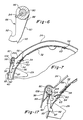
- Fig. 1 is a top, front and side perspective view of the automatic washer embodying the present invention having the lid and basket door flaps shown in the open position.
- Fig. 2 is a partially cut away side elevational view of the automatic washer of Fig. 1.
- Fig. 3 is a sectional view of the door flaps of the wash basket with the door flaps partially disengaged.
- Fig. 4 is a top, front and side perspective view of the second door flap of the present invention.
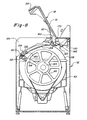
- Fig. 5 is a partially cut away front elevational view of the wash tub and wash basket of the present invention.
- Fig. 6 is a sectional view taken along lines VI-VI in Fig. 5.
- Fig. 7 is a sectional view of the door flaps, wash basket and tub of the present invention with the door flaps in their engaged position.
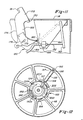
- Fig. 8 is a partially cut away side elevational view of the automatic washer of Fig. 1.
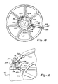
- Fig. 9 is an enlarged side elevational view taken along lines IX-IX in Fig. 5, showing the latching mechanism of the present invention.
- Fig. 10 is a sectional view taken along line X-X in Fig. 9.
- Fig. 11 is an enlarged side elevational view showing the lid mechanism of the present invention.
- Fig. 12 is a side sectional view showing the inner face of the pulley and the tripping mechanism of the present invention wherein the tripping mechanism is in a disengaged position.
- Fig. 13 is a side sectional view showing the inner face of the pulley and the tripping mechanism of the present invention wherein the tripping mechanism is in an engaged position.
- Fig. 14 is a circuit diagram for the automatic washer of Fig. 8.
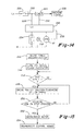
- Fig. 15 is a flow chart illustrating the steps implemented by the control system of the washing machine of Fig. 8 to carry out a method of positioning the wash basket according to the present invention.
- Fig. 16 is an enlarged partial side view of the tub of the present invention showing the cam in a disengaged position.
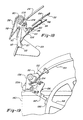
- Fig. 17 is an enlarged sectional view showing the holding arm, hook assembly and door flaps of the present invention.
- Fig. 18 is an enlarged sectional view showing the holding arm, hook assembly and door flaps of the present invention.
- Fig. 19 is an enlarged partial side view of the tub of the present invention showing the hub in a fully rotated clockwise position.
- Fig. 20 is a flow chart illustrating the steps implemented by the control system of the washing machine of Fig. 8 to carry out a method of initiating basket rotation after the basket has been positioned and held.
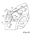
- Fig. 21 is a partial side elevational view of the automatic washer of Fig. 1, illustrating an alternative embodiment of the present invention.
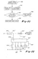
- Fig. 22 is a circuit diagram for the alternative embodiment of the automatic washer automatic washer of Fig. 21.
- Fig. 23 is a flow chart illustrating the steps implemented by the control system of the washing machine of Fig. 21 to carry out a method of positioning the wash basket according to the present invention.
- Fig. 24 is a flow chart illustrating the steps implemented by the control system of the washing machine of Fig. 21 to carry out a method of initiating basket rotation after the basket has been positioned and held.
- In Figs. 1 and 2, there is illustrated a top-loading drum-type
automatic washer 10 embodying the principles of the present invention. Thewasher 10 has anenclosure 12 generally defining afront surface 12a, aback surface 12b, opposite side surfaces 12c and 12d and atop surface 12e. The enclosure includes atop member 14, anouter cabinet 16 and anopenable lid 18, shown in an open position, which encloses animperforate wash tub 20. Thetop member 14 includes anaccess opening 22 extending partially along thetop surface 12e and thefront surface 12a for accessing the interior of theenclosure 12. Thewash tub 20 has an upwardly orientatedrectangular tub opening 24 having a front edge 24a. Theopening 24 is aligned with the access opening 22 and a slidablewash tub lid 26, shown in an open position, is provided for sealably closing theopening 24. - Disposed within the
wash tub 20 is a rotatable,perforate wash basket 28 having a rectangular basket opening 30 provided with an openablefirst door flap 32 and an openablesecond door flap 34. Each door flap includes afree edge portion 32a and 34a, respectively. The door flaps 32 34, shown in an open position, may be aligned with thetub opening 24 for allowing access into thewash basket 28 such that clothes may be loaded and unloaded from thewash basket 28. A plurality ofbaffles 29 may be disposed within thebasket 28, attached to the inner surface of thebasket 28 and extending inwardly for enhancing the tumbling action of the clothes items within thebasket 28 during a wash cycle. - The general construction of the
rotatable basket 28 and balancing disks 36 (Fig. 5) are shown and described in U.S. Patent No. 5,345, 792. - The
wash tub 20 is formed by a two piece construction including anupper tub member 38 and alower tub member 40. Thetub 20 is supported within theenclosure 12 bystruts 42 extending from thelower tub member 40 to aframe 44. Amotor 46 is supported from thelower tub member 40 and is drivably connected to apulley 48 by abelt 50. Thepulley 48 is drivably interconnected with thebasket 28 such that themotor 46 may rotate thebasket 28 within the tub. - The
automatic washer 10 is configured to ease loading and unloading of clothes items into thewash basket 28. As described above, the access opening 22 is configured to extend partially along thetop surface 12e andfront surface 12a such that clothes items being loaded and unloaded from thewash basket 28 must be raised only to the height of afront lip portion 52 of thetop member 14 to pass through theaccess opening 22. The ratio of the overall height H1 of theenclosure 12 to the distance H2 from the bottom of theenclosure 12 to thefront lip portion 52, when measured in like units, is approximately 1.16. Further, the access opening 22 extends along thetop surface 12e such that the ratio of the overall depth D1 of theautomatic washer 10 to the overall length D2 of the access opening 22 is 1.4. It can be seen, therefore, that access opening 22 provides a relatively large front angled opening for accessing the interior of thewash basket 28. - The
lid 18 is configured to completely cover theaccess opening 22. The lid therefore includes afirst portion 51 extending along thetop surface 12e and asecond portion 53 extending alongfront surface 12a. - The
top member 14 includes downwardly sloped side interior walls 55a and 55b which are disposed along the side edges of theaccess opening 22. These side interior walls extend from thetop surface 12e to the edge of the access opening 22 for providing a funnelling effect such that clothes being loaded into thewash basket 28 are downwardly directed under the urgings of gravity along the side interior walls 55a and 55b into thewash basket 28. - The door flaps 32 and 34 are configured to further enhance operator access into the
wash basket 28. As best seen in Figs. 2 and 3, thefirst door flap 32 is relatively large, having an arc length approximately equal to size of thebasket opening 30. Thesecond door flap 34 is relatively small in comparison to thefirst door flap 32. As contemplated by the inventors, thefirst door flap 32 has an arc length of approximately 32.5 cm (13") and thesecond door flap 34 has an arc length of approximately 7.5 cm (3"). The door flaps are hinged at mutually opposite edges 30a and 30b of therectangular opening 30 and are partially overlapped when they are closed. The door flaps 32 and 34 are curved throughout their width in such a way that, when they are in their closure position, the outline of theflaps respective torsion spring second door flap 34 is atab 63 for limiting the rotation of thesecond door flap 34 about thehinge point 54. - When the basket opening 30 is correctly aligned with the
tub opening 24, the door flaps may be opened for allowing access through theopening 30 into the interior of thebasket 28. When theflaps second door flap 34 is urged upwardly and is positioned adjacent the front edge 24a of thetub opening 24. Thetab 63 limits the rotational travel of thesecond door flap 34 and positions thesecond door flap 34 partially closed at a predetermined angle relative to a tangential line to thebasket 28 having thehinge point 54 as a tangent point. The predetermined angle is preferably approximately 45°. Thefirst door flap 34 is also urged upwardly when opened and is rotationally limited and positioned against thelid 18. It can be seen, therefore, that the asymmetrical configuration of the door flaps is such that the door flaps 32 and 34, when opened, do not hinder access into the interior of thewash basket 28. Specifically, thesecond door flap 34 extends just beyond the front edge 24a but does not interfere with loading and unloading clothes due to its small size while the much larger second door flap is positioned against thelid 18 out of the path of loading and unloading clothes items into thewash basket 28. - Closure of the door flaps 32 and 34 is achieved by downwardly forcing the open
first door flap 32. The resultant downward rotation of the first door flap causes thefree edge 32a of thefirst door flap 32 to catch the free edge 34a of thesecond door flap 34. This is possible due to the fixed angle, partially closed position in which thesecond door flap 34 is held bytab 63 when in its open position, which positions the free edge 34a of thesecond door flap 34 in the arc traced by thefree edge 32a of thefirst door flap 32 when thefirst door flap 32 is moved from an open position to a closed position. In this fashion, both of the door flaps 32 and 34 may be engaged by only downwardly urging thefirst door flap 32. - As shown in Figs 3 and 4,
apertures 64,side hook members 66 andcenter hook member 68 are respectively provided along thefree edges 32a and 34a of the door flaps in such a position as to permit theapertures 64 andhook members first door flap 32 is pushed downwardly. The hook members are configured to provide a highly reliable latching system for the door flaps 32 and 34 wherein all of the hook members properly engage their respective apertures. It can be seen that thehook members center point 70 such that thecenter hook 68 is the tallest hook member and has a vee shaped contact point. In this fashion, thecenter hook 68 is the first hook to engage its respective aperture even if the first door flap is twisted or forced downwardly with an off-center force. The side hooks 66 are configured having a s-curved shape wherein the top edges 66a of the side hooks are bent forward, away from premature contact and engagement with the matching first door flap piece. With the s-curve shape, the side hooks 66 are further prevented from latching prior to thecenter hook 68. - The above described door flap and basket construction allows for a relatively large
diameter wash basket 28 in comparison to the overall height of thewasher 10. Typically, in order to prevent the door flaps of a top loading horizontal washer from interfering with basket access, a lengthy tub access conduit is provided, extending from the top surface of the washer to the basket opening. However, due to the above described structure, in the present invention the basket opening 30 can approach thetop surface 12e of thewasher 10 such that the basket opening 30 is positioned relatively close to thetop surface 12e of the washer. This allows the basket diameter to be relatively large in comparison to the overall height of thewasher 10. As contemplated by the inventors, the ratio of overall height H1 of theenclosure 12 to the diameter of thebasket 28, when measured in like units, is approximately 1.7. - Turning now to Fig. 5-7, a
control shaft 80 is shown supported within thetub 20 and disposed adjacent therotatable basket 28. Thecontrol shaft 80 is rotatably supported at opposite ends by theupper tub member 38 and includes at least one end extending through theupper tub member 38 wherein a rotary positioning member orrotary positioning hub 82 is secured to thecontrol shaft 80 outside theupper tub member 38. Alatching mechanism 84 is provided adjacent thehub 82 for latching thehub 82 in a predetermined position, as described in detail herein further below. Thehub 82, latchingmechanism 84 andpulley 48 are shown disposed on the right hand side of thetub 20 but could be disposed on the opposite side and function in an identical fashion, as can be understood by one skilled in the art. The below description makes frequent reference to rotational directions by using the terms "clockwise" and "counter-clockwise". It can be understood by those skilled in the art that these terms are used with respect to a right side view perspective as illustrated in Figs. 7, 9, 11, and 14-17. - The
control shaft 80 supports a holdingarm 86 adjacent therotatable basket 28 which may be controlled for engaging astop opening 87 provided in thewash basket 28 for positioning thebasket 28 during loading and unloading. As shown, one of thebaffles 29 may be preferably positioned over thestop opening 87. As best shown in Fig. 6, the holdingarm 86 includes aboss portion 88 surrounding thecontrol shaft 80 and aleg portion 90 having a hook-like catch portion 92 provided at the end of theleg portion 90. Anengagement finger 93 is provided extending from thecatch portion 92 for limiting engagement of the holdingarm 86 with the basket stop opening 87. Apin 94, extending from thecontrol shaft 80, engages aslot 96 provided on theboss 88 of the holdingarm 86 for controlling relative rotation of the holdingarm 86 about thecontrol shaft 80. Atorsion spring 98 is provided for urging the holdingarm 86 toward thebasket 28 in a counter-clockwise direction. - A
tab engagement arm 100 is also supported by thecontrol shaft 80 adjacent thebasket 28 which may be controlled for engaging thetab 63 extending from thesecond door flap 34 wherein the door flaps 32 and 34 may be released from a closed position to an open position. As seen in Figs. 5 and 7, thetab engagement arm 100 includes adrive arm member 104 which is rigidly secured to thecontrol shaft 80 for rotation therewith, and atab hook 106 being hingedly mounted at the end of thedrive arm 104. Aspring 108 is provided for biasing thetab hook 106 toward thebasket 28 wherein thetab hook 106 is positioned by the hinged connection and thespring 108 to extend straight from thedrive arm 104 radially away from the center of thedrive shaft 80. - Turning now to Fig. 8, the
hub 82 attached to thecontrol shaft 80 is shown along with thelatching mechanism 84 and alid mechanism 120. These systems operate to control the rotation of thecontrol shaft 80 to actuate the holdingarm 86 and thetab engagement arm 100 for positioning thebasket 28 and opening the door flaps 32 and 34, as will be described herein below. - In Figs. 9 and 10, the
hub 82 is shown in detail, held in its engaged position by thelatching mechanism 84. Thehub 82 is preferably a thermoplastic member and is secured to thecontrol shaft 80 by ascrew 123. Atorsion spring 124 is provided for urging thehub 82 to rotate clockwise as shown. The torque applied to thecontrol shaft 80 byspring 124 is less than the torque applied to the shaft byspring 98. Thehub 82 is generally fan shaped and includes anotch 126 and anouter surface 127. Ahook portion 128 is provided along with acable guide surface 130 such that acable 132, extending from thelid mechanism 120, may be secured to thehub 82. Ahub switch 234 is secured to theupper tub 38 adjacent thehub 82 for sensing rotation of the hub. In particular, the orientation of thehub switch 234 is such that rotation of thehub 82 corresponding to engagement of the holdingarm 86 into thestop opening 87 is sensed. - The
latching mechanism 84 includes a latchinglever 134 and a trippinglever 136. These levers are contemplated to be metallic and formed by a sheet steel stamping operation. Thelevers upper tub member 38 by ashaft 138 having a threaded retainingend 140. The latchinglever 134 is provided with acatch flange 142 for engaging thenotch 126 provided on thehub 82. Atorsion spring 144 is provided for urging the latchinglever 134 toward thehub 82. The latchinglever 134 is further provided with atab 145 which extends from thelever 134 outwardly through aslot 146 provided in the trippinglever 136. In this fashion, thelevers spring 149 is provided for urging the latchinglever 134 counter-clockwise toward thehub 82 relative to the trippinglever 136. - The tripping
lever 136 is provided with afirst arm portion 147 extending toward thepulley 48 and asecond arm portion 148. Thesecond arm portion 148 is provided with a flange portion 150 having ahole 152. A connectingrod 154 interconnected with thehub 82 extends through thehole 152 of the flange 150. Aspring 156 is positioned between the flange 150 and acollar 158 provided on therod 154, such that thehub 82 and trippinglever 136 are resiliently interconnected with each other. - As mentioned above and shown in Fig. 8 and 11, the
lid mechanism 120 may operate to control the rotation of thecontrol shaft 80 when thebasket 28 is positioned and holdingarm 86 is in thestop opening 87. Thelid mechanism 120 is interconnected directly to thehub 82 by thecable 132 which may be enclosed in acasing 159 wherein thecasing 159 is secured to theupper tub 38 by bracket 160. Thecable 132 is attached to acam follower lever 162, at the end opposite attachment to thehub 82. Thecam follower lever 162 is rotatably supported by a cam bracket 164 which is secured to the top 14 and which also provides a surface for attaching abracket 166 which slidably supports thecable 132. - Extending from
lid 18 is alid hinge 168 which hingedly connects thelid 18 with the top 14 athinge point 170. Thelid hinge 168 includes afirst portion 172 secured to thelid 18 and asecond portion 174 extending beyond thehinge point 170 which supports alid hinge cam 176. Thelid hinge cam 176 includes acam surface 178 which slidably engages a cam follower end 180 of thecam follower lever 162. Thecam surface 178 is configured such that moving the lid from a closed position to an open position causes the cam surface to engage the cam follower end 180 such that thecable 132 is moved from a first rest position to a second forward position and back to the first rest position. - In Figs. 12 and 13, the inward face of the pulley is shown including a tripping
mechanism 182. The trippingmechanism 182 is associated with thepulley 48 and operates to trip thelatching mechanism 84 and to reset thelatching mechanism 84. The trippingmechanism 182 is designed such that during normal clockwise rotation of thepulley 48, no engagement with the latching mechanism occurs. However, when access to thebasket 28 is desired, rotation of thepulley 48 is reversed to a counter-clockwise rotation wherein the trippingmechanism 182 engages thelatching mechanism 84 so that the holdingarm 86 is released to engage the stop opening 87 for positioning thebasket 28. When the rotation of thebasket 28 is desired to be resumed, the tripping mechanism 122 operates to again engage thelatching mechanism 84 to reset it, drawing the holdingarm 86 away from thebasket 28. - Pulley rotation is required for causing the tripping
mechanism 182 to trip and reset thelatching mechanism 84. However, it can be understood that until thelatching mechanism 84 is reset, drawing the holdingarm 86 out of the stop opening 87 of thebasket 28, thebasket 28 can not rotate. Therefore, a two piece pulley system is required which provides for lost motion of thebasket 28 while thepulley 48 rotates to reset the latching mechanism. - The
pulley 48, therefore, is slidingly disposed about adrive hub 184 which is rigidly attached to a basket drive shaft 185 for driving thebasket 28. Thepulley 48 is supported by thedrive hub 184 in such a manner that limited relative rotation between thedrive hub 184 and thepulley 48 may occur. To accomplish this limited relative rotation, thepulley 48 is provided with a inwardly extendingdrive dog 186 which rides within aslot 188 provided on the outer diameter of thedrive hub 184.End walls slot 188 for interfering with the movement of thedrive dog 186 within theslot 188 such that thepulley 48 may rotate a limited angular distance relative to thedrive hub 184 and then engage the hub for co-rotation. It is contemplated by the inventors that thepulley 48 anddrive hub 184 may be constructed of different types of plastic material and slidingly engage each other along their inner and outer periphery, respectively. - The tripping
mechanism 182 further includes atrip arm 192 having acam follower end 194 and atrip end 196. Thetrip arm 192 includesslots 197 through which shoulderedfasteners 198 are placed for securing thetrip arm 192 to thepulley 48 for allowing axial movement of thetrip arm 192 relative to thepulley 48. Thecam follower end 194 is positioned in atrack 200 provided in thehub 184. Thetrack 200 includes acam portion 202 and andinner track 204. - As can be seen in Fig. 12, when the
pulley 48 is driven in a clockwise direction for driving thebasket 28, thepulley 48 rotates around thedrive hub 184 until thedrive dog 186 is driven into theend wall 190a. This rotation of thepulley 48 around thedrive hub 184 positions thecam follower end 194 within theinner track 204 wherein thetrip end 196 is positioned in a first position such that thetrip end 196 does not engage thelatching mechanism 84 during the basket/pulley co-rotation. However, as shown in Fig. 13, when the direction of the pulley rotation is changed such that thepulley 48 is driven in a counter-clockwise rotation, thepulley 48 rotates about thedrive hub 196 until thedrive dog 186 is driven into theend wall 190b. This rotation of thepulley 48 around thedrive hub 184 positions thecam follower end 194 within thetrack 200 wherein thetrip end 196 is positioned in a second position having thetrip end 196 positioned radially outward for engaging the latching mechanism when thetrip end 196 is rotated past thelatching mechanism 84. - Fig. 14 illustrates a simple circuit diagram for the above described
automatic washer 10. Alid switch 220 is provided associated with thelid 18 for breaking the power supply to the automatic washer upon opening thelid 18.Line 222 connects thelid switch 220 with atimer 224 for controlling the operation of various components of the washer. Thetimer 224 includes a plurality of switches for controlling a plurality of machine loads 226, as is known. Aline 228 extends fromline 222 to a printed circuit board (PCB) orcontrol board 230, including a microprocessor. Additionally, aline 232 extends from the timer to thecontrol board 230. - As is known to one skilled in the art, the
timer 224 contains a line switch (not shown) for energizing the timer such that closing the line switch energizes the timer and opening the line switch deenergizes the timer. Frequently, the timer line switch may be operated by the user by pushing/pulling on the timer knob. Once the timer is energized by closing the timer line switch,line 232 provides a 110 v signal input to the printedcircuit board 230, which is energized throughline 228. Thecontrol board 230 further receives a signal input from thehub switch 234 and selectively energizes anindicator light 236 and themotor 46. The motor may be a 220 v. DC variable speed universal motor. A tachometer feed-back line 238 provides a motor speed sensitive signal back to thecontrol board 230. Included in thecontrol board 230 is a reversing relay for operating themotor 46 in either a clockwise or counter-clockwise direction. - Turning now to Figs. 15-17, the operation of the latching
mechanisms 84, thelid mechanism 120, and the trippingmechanism 182 for causing rotation of thecontrol shaft 80 may be shown. These mechanisms operate to automatically position and hold thebasket 28 in its load/unload position as well as automatically opening thebasket doors lid 18 is opened. These operation, moreover, require only a basic control system as illustrated in Fig. 15. - During washer operation, the
basket 28 must be free to to rotate within thetub 20 requiring that the holdingarm 86 andtab engagement arm 100 be held in a disengaged position, away from thebasket 28, as illustrated in Fig. 7. Corresponding to the disengaged position of the holdingarm 86 andtab engagement arm 100, thehub 82 andcontrol shaft 80 are held in a predetermined angular position, shown in Fig. 9, which may be termed angular position "A". It may be understood, therefore, that when the control shaft is held in the angular position "A", the holdingarm 86 and thetab engagement arm 100 are positioned away from thebasket 28 such that thebasket 28 is free to rotate. Thehub 82, is held, against the counter-clockwise rotational urgings of thespring 98, in its respective position by the engagement of the latchinglever 134 with thenotch 126 on thehub 82. - Wash basket auto-positioning and holding is initiated when the
timer 224 is deenergized, as shown instep 242 of Fig. 15. Timer deenergization occurs automatically at the conclusion of a completed wash cycle and may also occur as a result of operator wash cycle interruption. In both cases, the timer line switch is opened, deenergizing the timer, which is sensed by thecontrol board 230 throughsignal input line 232, as shown instep 242. Instep 244, subsequent to the timer deenergization, the motor is deenergized and theindicator light 236 is flashed to signal to the user that the basket is being automatically positioned. Motor speed is sensed instep 246, determining when basket rotation has stopped or is less than a predetermined value. This basket "coast down" time may vary based on the wash load size and balance within thebasket 28 and whether thebasket 28 was in a high speed spin or low speed tumble. Motor speed sensing may be replaced by a simple hold time, long enough to ensure that basket rotation has slowed or stopped. Once the rotation of thebasket 28 in a clockwise direction has slowed sufficiently or stopped, thepulley 48 is driven in a counter-clockwise direction by themotor 46, as shown instep 248. - As described above, driving the
pulley 48 in a counter-clockwise direction causes the trip end 196 of the trippingmechanism 182 to move to the second position, shown in Fig. 13, for engaging thefirst arm portion 147 of the trippinglever 136. As shown in Fig. 16, when the radially extendedtrip end 196 is rotated past thefirst arm portion 147, thetrip end 196 engages thefirst arm portion 147 and causes the trippinglever 136 to rotate in a clock-wise direction about theshaft 138. The latchinglever 134 rotates with the trippinglever 136 as a result of the engagement created by thetab 145 extending through theslot 146. The rotation of the latching lever pulls thecatch flange 142 off of thenotch 126 such that thehub 82 is disengaged from the latchinglever 134 wherein, under the urgings of thespring 98, thehub 82 and thecontrol shaft 80 rotate in a counter-clockwise direction. - As a result of this counter-clockwise rotation of the
control shaft 80, the holdingarm 86 is urged into therotating basket 28. As shown in Fig. 17, engagement between thebasket 28 and the holdingarm 86 occurs upon alignment of thecatch portion 92 of the holdingarm 86 with the stop opening 87 in thebasket 28. This position of thecontrol shaft 80 maybe called angular position "B". - In
step 250, holding arm engagement into thestop opening 87 is sensed by thehub switch 234. Alternately, holding arm engagement may be determined by sensing a locked rotor condition of themotor 46. Upon sensing that the holdingarm 86 has engaged with thestop opening 87, themotor 46 is deenergized, as shown instep 252. Finally, instep 254, thecontrol board 230 is deenergized which simultaneously deenergizes the flashingindicator light 236. - It can be understood, therefore, that simple rotation of the
pulley 48 and thebasket 28 in a reverse direction from the direction of rotation during the wash cycle, operates to secure thebasket 28 in the desired position for loading and unloading clothes items. The use of the thetrip arm 192 for releasing thelatching mechanism 84 thereby actuating the holdingarm 86 ensures that the holdingarm 86 is driven into therotating basket 28 just prior to alignment between thecatch portion 92 with thestop opening 87. In this fashion, the holdingarm 86 does not drag across a large portion of the outer circumference of thebasket 28, which may result in undue holding arm wear, undue noise and possible misoperation. It can be seen, therefore, that the present invention provides a system requiring only a very basic control system for automatically positioning thebasket 28 for loading and unloading clothes items. - Once the
basket 28 is properly positioned and held as described above, thelid 18 may be opened for accessing thebasket 28. As described above, thelid mechanism 120 is such that opening thelid 18 causes thecable 132 to move from its first rest position to its second forward position and back to the first rest position. Figs. 18 and 19 show the effect moving thecable 132 to the second forward position has on thehub 82 rotation. As shown, the movement of thecable 132 to the second forward position rotates thehub 82 andcontrol shaft 80 against the biasing oftorsion spring 124 beyond the relative angular position "B" to a new angular position "C", such that thehook mechanism 100 is driven to engage thedoor flap tab 63. - During rotation of the control shaft from position "B" to position "C", the holding
arm 86 remains in its engaged position with thebasket 28 while thecontrol shaft 80 rotates relative to the holdingarm 86. This is possible due to the pin and slot connection between the holdingarm 86 and thecontrol shaft 80, as described above. The resultant engagement between thetab hook 106 and thetab 63 rotates thesecond door flap 34 clockwise wherein thehooks apertures 64, such that the door flaps 32 and 34 are disengaged. Upon disengagement, the first door flap is urged open in response to thelid spring 56. Upon complete opening of thelid 18, thecable 132 is moved back to the first position, as described above, wherein thecontrol shaft 80 returns to the angular position "B". This rotational movement back to angular position "B", causes the seconddoor flap tab 63 to be released from thetab hook 106 whereupon thesecond door flap 34 is urged open bydoor spring 54. - In this fashion, therefore, opening the
lid 18 results in the disengagement of the door flaps 32 and 34 such that the door flaps appear to open simultaneously with the opening of thelid 18 for accessing thebasket 28. Further, the basket door opening system is a completely mechanical system, requiring no control logic or control system. - Disengagement of the holding
arm 86 from thestop opening 87 is necessary to re-initiate basket rotation after the interior of thebasket 28 has been accessed. To accomplish this disengagement, thelatching mechanism 84 must be reset from angular position "B" to angular position "A" such that holdingarm 86 is disengaged from thebasket 28. Fig. 20 illustrates the control sequence for reinitiating basket rotation during a washer power-up routine. As shown instep 260, thecontrol board 230 senses timer energization. Instep 262, themotor 46 is energized to drive the pulley clockwise approximately one revolution. Due to the above described basket positioning system, at the initiation of the washer power-up, when wash basket rotation is desired after the basket has been positioned and held, thetrip arm 192 is positioned angularly in a counter-clockwise direction just beyond thefirst arm portion 147. - The clockwise rotation of the pulley operates to reset latching
mechanism 84 and thereby reset the holdingarm 86 in its disengaged position. Due to the limited relative rotation provided between thepulley 48 and thehub 184, thepulley 48 rotates about thehub 184 until thedrive dog 186 is driven into thesurface 190a. Thetrip arm 192 remains in the radially extended position until thecam follower end 194 engages thecam surface 202 and moves to theinner track 204. This results, therefore, in thetrip end 196 engaging thefirst arm portion 147 in a clockwise direction, causing the trippinglever 136 to rotate in a counter-clockwise direction about theshaft 138. The interconnection between the trippinglever 136 and thehub 82 throughrod 154 is such that the counter-clockwise rotation of the trippinglever 136 drives thehub 82 to rotate in a clockwise rotation. Thelatch lever 134 rides along theouter surface 127 of thehub 82 until thehub 82 has rotated thecontrol shaft 80 back to the angular position "A" wherein the catch flange engages thenotch 126. This clockwise rotation of thecontrol shaft 80 disengages the holdingarm 86 from thestop opening 87. - Disengagement of the holding
arm 86 from thestop opening 87 may be sensed by sensing hub rotation with thehub switch 234, as shown instep 264. Instep 266, if thehub switch 234 does not sense the hub rotation, indicating a failure mode, the machine is deenergized. However, if as expected, thehub switch 234 senses hub rotation to angular position "A", the wash cycle continues, as shown instep 268. - In this fashion, the latching mechanism is reset by clockwise rotation of the
pulley 48 while thetrip arm 192 remains in the radially extending position. However, as described above, after a limited relative rotation between thepulley 48 andhub 184, thetrip arm 192 returns to its disengaged position such that successive relative rotation of thetrip end 196 past the trippinglever 136 does not result in contact between thetrip end 196 and thefirst arm position 147. - In Fig. 21 an alternative embodiment of the present invention is illustrated. In this system, the strictly
mechanical latching mechanism 84, described above, is replaced with a latching system including electro-mechanical elements. - As shown, the latching mechanism of the alternative embodiment includes a latching lever 134' and a tripping lever 136' for operation in a similar fashion to the latching
lever 134 and the trippinglever 136. A hub 82' is provided rigidly attached to a shaft 80' for controlling the angular position of the the shaft 80'. Attached to the shaft 80' are a holding arm 86' and elements for opening the basket doors similar to those described above. - In contrast to the two piece pulley system described above, however, the alternative embodiment includes a single piece pulley 48' having a fixed
trip member 280 for engaging the tripping lever 136'. Atrip solenoid 282 is interconnected with the tripping lever 136' for selectively positioning the tripping lever 136' in a position for engagement with thetrip member 280. In contrast to the trippinglever 136, the tripping lever 136' must be rotated clockwise toward the pulley 48' for engagement with thetrip member 280 and rotated away from the pulley during normal washer operation when engagement between thetrip member 280 and the tripping lever 136' is not desired. Further, areset solenoid 284 is connected with the hub 82' for resetting the hub thereby disengaging the holding arm 86' from a stop opening 87'. - The circuit diagram of the control system for the alternative embodiment, illustrated in Fig. 22, is similar to Fig. 14. However, the
solenoids - The operation of the alternative embodiment may be understood by referring to Fig. 23. In
step steps trip solenoid 282 is energized by the control board 230', as shown instep 290, such that the tripping lever 136' is rotated down into a position for engagement with thetrip member 280. Instep 292, the motor is driven in a direction for driving the pulley 48' in a counter-clockwise direction. In this manner, thetrip member 280 is driven into the tripping lever 136' thereby rotating the tripping lever 136' in a clockwise direction. This clockwise rotation of the tripping lever 136' is allowed by providing aslot 294 for slotted engagement with thetrip solenoid 282. In a like manner to the description above regarding the rotation of the trippinglever 136, the rotation of the tripping lever 136' causes the holding arm 86' to drive into the rotating basket 28' for engagement with a stop opening 87' thereby positioning and holding the basket 28'. - In
step 294, the holding arm engagement is sensed through a micro-switch 234' or through a locked rotor motor condition, as described above. Subsequently, instep 296, the motor 46' is deenergized and instep 298 thetrip solenoid 282 is deenergized, moving the tripping lever 136' away from the pulley 48'. Finally, as shown instep 300, the control board is deenergized. - As can be understood by one skilled in the art, prior to reinitiating basket rotation, the holding arm 86' must be disengaged from the stop opening 87'. In Fig. 24, the power-up routine for the alternative embodiment of the present invention is illustrated. In
step 302, timer energization is sensed by the control board 230'. Instep 304, thereset solenoid 284 is momentarily energized or pulsed, which rotates the hub 82' and control shaft 80' in a clockwise direction, disengaging the holding arm 86' from the stop opening 87' and allowing the latching lever 134' to engage a hub notch for holding the hub 82' in an angular position "A'" such that the holding arm is disengaged from the basket 28'. Instep 306 the motor is energized for initiating the wash basket 28' rotation and subsequently operating thewasher 10 in the selected wash cycle. - It can be seen therefore, that the present invention provides a top loading automatic washer having an automatic basket positioning and holding system for orienting the basket during loading and unloading. This system requires only a simple control system and is relatively inexpensive. Further, the use of a holding arm for direct engagement with the basket ensures simple and highly accurate positioning of the basket.
- Although the present invention has been described with reference to specific embodiments, those of skill in the Art will recognize that changes may be made thereto.
- For example, the stop opening 87 described above, could be replace by a structure or member extending from the wash basket for engagement with the holding
arm 86. In this fashion, the wash basket could be engaged, in a like fashion as described above, for correctly positioning the basket for loading and unloading clothes to and from the wash basket. - Additionally, the holding
arm 86 could be acutated directly by a solenoid arrangement, rather than the mechanical linkage system disclosed above. For example, the holding arm may comprise a member interconnected with a actuator such that the holding arm is supported for linear motion wherein the holding arm may engage the wash basket.
Claims (13)
- A method of positioning a rotatable basket (28) within an automatic washer (10) for loading and unloading clothes items into the basket (28), said basket (28) having a horizontal axis and being disposed within tub (20), said basket (28) further being rotatably driven by a motor (46), said method comprising the steps of:(1) slowly rotating said basket (28) within said tub (20);(2) actuating a holding arm (86), disposed adjacent said basket (28) and having a holding end (92), to bias toward said rotating basket (28);(3) engaging said basket (28) with said holding end (92) such that said basket (28) is rotatably fixed;(4) sensing said engagement of said basket (28) with said holding end (92); and(5) deenergizing said motor (46); characterised in that said automatic washer (10) further includes a control shaft (80) for rotatably supporting said holding arm (86), the control shaft (80) being rotatably supported by said tub (20) and having an end extending external of said tub (20); a hub (82) rigidly attached to said externally extending end of said control shaft (80); a spring (98) for biasing said holding arm (86) toward said basket (28) and a latching mechanism (84) disposed adjacent said hub (82) for selectively engaging said hub (82) to latch said control shaft (80) in a predetermined angular position for resisting the urgings of said spring (98), said step of actuating said holding arm (86) further comprising:
tripping said latching mechanism (84) such that said holding arm (86) is released for rotation toward said rotating basket (28). - The method of positioning a rotatable basket (28) within an automatic washer (10) according to claim 1, wherein the wash basket (28) further includes a stop opening (87) and wherein:step 2 further includes actuating said holding arm (86) just prior to alignment of said holding end (92) with said stop opening (87); andstep 3 further includes engaging said holding end (92) into said stop opening (87).
- The method of positioning a rotatable basket according to claim 1, wherein the automatic washer (10) further includes a timer (224) for selectively energizing a plurality of machine components, said method of positioning the rotatable basket (28) further comprising the steps of :sensing timer deenergization; anddeenergizing said motor (46) until said motor (46) has deaccelerated and then initiating step 1.
- The method of positioning a rotatable basket according to claim 1 wherein the automatic washer (10) further includes a tripping mechanism (192) associated with a pulley (48) drivingly connected to said basket (28), said step of tripping said latching mechanism (84) further comprises:actuating said tripping mechanism (192) disposed on said pulley (48); androtating said tripping mechanism (192) past said latching mechanism (84) such that said latching mechanism (84) is tripped.
- An automatic washer (10), comprising:a tub (20);a perforate wash basket (28) disposed within said tub (20) being rotatable about a horizontal axis;a motor (46) drivingly connected with said wash basket (28) for selectively rotating said wash basket (28) about said horizontal axis;a holding arm (86) supported adjacent said wash basket (28) and having a holding end (92) for selectively engaging said wash basket (28) for positioning said wash basket (28) relative to said tub (20); characterised by:a control shaft (80) rotatably supported by said tub (20) and having a main portion disposed adjacent said basket (28) and an end extending external of said tub (20);said holding arm (86) being interconnected with said main portion of said control shaft (80);a hub (82) rigidly attached to said externally extending end of said control shaft (80);a spring (98) for biasing said control shaft (80) to rotate such that said holding arm (86) is urged toward said basket (28); anda latching mechanism (84) disposed adjacent said hub (82) for selectively engaging said hub (82) in a predetermined angular position for resisting the urgings of said spring (98);wherein selective disengagement of said latching mechanism (84) from said hub (82) releases said control shaft (80) to rotate such that said holding end (92) is driven toward said wash basket (28) for engaging said wash basket (28) for positioning said wash basket (28) relative to said tub (20).
- The automatic washer (10) according to claim 5, wherein said wash basket (28) further includes a stop opening (87) and wherein said holding end (92) selectively engages said stop opening (87).
- An automatic washer (10) according to claim 5 wherein said holding end (92) is hook-shaped.
- An automatic washer (10) according to claim 6, wherein said holding end (92) has a finger (93) extending therefrom for limiting the engagement of said holding end (92) with said stop opening (87).
- An automatic washer (10) according to claim 5, further comprising:
means (192) for tripping said latching mechanism (84) such that said hub (82) is released such that said control shaft (80) rotates under the urgings of said spring (98). - An automatic washer according to claim 5, further comprising:a pulley (48) drivingly interconnected with said basket (28) and said motor (46) for rotating said basket (28);a latching lever (134) rotatably supported adjacent said hub (82) for engaging a notch (126) on the hub (82) for latching said hub (82) in said predetermined angular position,a tripping lever (136) rotatably supported adjacent said latching lever (134) and interconnected with said latching lever (134) for rotation with said latching lever (134), said tripping lever (136) having a portion extending toward said pulley (48); andmeans (192) extending from said pulley (48) for engaging said portion of said tripping lever (136) for rotating said tripping lever (136) and latching lever (134) for disengaging said latching lever (134) from said notch (126) such that said control shaft (80) is released for rotation under the urgings of said spring (98).
- A method of initiating the rotation of a rotatable basket (28) within an automatic washer (10), said basket (28) having a horizontal axis and being disposed within a tub (20), said basket (28) having a holding arm (86) for engaging the wash basket (28) for positioning and holding the basket (28) which may be rotatably driven by a motor (46), said method comprising:(1) disengaging a holding arm (86) from the wash basket (28) such that free basket rotation is allowed;(2) sensing said disengagement of said holding arm (86) from said wash basket (28); and(3) rotating said basket (28); characterized in that said automatic washer (10) further includes a control shaft (80) for rotatably supporting said holding arm (86), the control shaft (80) being rotatably supported by said tub (20) and having an end extending external of said tub (20); a hub (82) rigidly attached to said externally extending end of said control shaft (80); a spring (98) for biasing said holding arm (86) toward said basket (28) and a latching mechanism (84) disposed adjacent said hub (82) for selectively engaging said hub (82) to latch said control shaft (80) in a predetermined angular position for resisting the urgings of said spring (98), said step of disengaging said holding arm (86) further comprising:
relatching said said latching mechanism (84) such that said holding arm (86) is disengaged from said said basket (28). - The method of initiating the rotation of a rotatable basket (28) according to claim 11, wherein the automatic washer (10) further includes a timer (224) for selectively energizing a plurality of machine components, said method of positioning the rotatable basket (28) further comprising the steps of:sensing timer energization; andenergizing said motor (46) for disengaging said holding arm (86) from said wash basket (28).
- A method of initiating the rotation of a rotatable basket (28) according to claim 11 wherein the automatic washer (10) further includes a tripping mechanism (192) associated with a pulley (48) drivingly connected to said basket (28), said step of relatching said latching mechanism (84) further comprises:actuating said tripping mechanism (192) disposed on said pulley (48); androtating said tripping mechanism (192) past said latching mechanism (84) such that said latching mechanism (84) is relatched.
Applications Claiming Priority (2)
| Application Number | Priority Date | Filing Date | Title |
|---|---|---|---|
| US236822 | 1994-05-02 | ||
| US08/236,822 US5469593A (en) | 1994-05-02 | 1994-05-02 | Basket positioning system for a top loading horizontal axis automatic washer |
Publications (3)
| Publication Number | Publication Date |
|---|---|
| EP0681050A2 EP0681050A2 (en) | 1995-11-08 |
| EP0681050A3 EP0681050A3 (en) | 1997-07-09 |
| EP0681050B1 true EP0681050B1 (en) | 2001-10-04 |
Family
ID=22891112
Family Applications (1)
| Application Number | Title | Priority Date | Filing Date |
|---|---|---|---|
| EP95302953A Expired - Lifetime EP0681050B1 (en) | 1994-05-02 | 1995-05-01 | Basket positioning system for a top-loading horizontal axis automatic washer |
Country Status (11)
| Country | Link |
|---|---|
| US (1) | US5469593A (en) |
| EP (1) | EP0681050B1 (en) |
| KR (1) | KR950032817A (en) |
| CN (1) | CN1124799A (en) |
| AU (1) | AU682258B2 (en) |
| CA (1) | CA2148151A1 (en) |
| DE (1) | DE69522991T2 (en) |
| ES (1) | ES2161268T3 (en) |
| NZ (1) | NZ272036A (en) |
| PH (1) | PH31532A (en) |
| TW (1) | TW317583B (en) |
Families Citing this family (37)
| Publication number | Priority date | Publication date | Assignee | Title |
|---|---|---|---|---|
| US5875655A (en) * | 1996-06-11 | 1999-03-02 | Whirlpool Corporation | Additive dispenser for an automatic washer |
| FR2772798B1 (en) * | 1997-12-23 | 2000-06-30 | Electrolux Syst Blanchisserie | WASHING MACHINE HAVING A DRUM DOOR WITH AUTOMATIC OPENING |
| FR2778678B1 (en) * | 1998-05-15 | 2000-08-04 | Ciapem | DEVICE FOR AUTOMATICALLY OPENING THE GATE OF A WASHING OR DRYING MACHINE |
| US7073356B2 (en) * | 2001-09-28 | 2006-07-11 | Sanyo Electric Co., Ltd. | Drum type washing machine |
| AU2002250159A1 (en) * | 2002-02-14 | 2003-09-04 | G.A. Braun, Inc. | Automatic loading extractor |
| US20040098812A1 (en) * | 2002-11-26 | 2004-05-27 | Herzog Rollie Richard | Clothes washer speed detection and lid lock systems and methods |
| US7013682B2 (en) * | 2003-05-23 | 2006-03-21 | Equator Corportion | Laundry machine door assembly and method |
| EP1544343B1 (en) * | 2003-12-19 | 2007-10-10 | Whirlpool Corporation | Top-loading washing machine with a drum equipped with a single door flap |
| KR101054402B1 (en) * | 2004-02-06 | 2011-08-04 | 엘지전자 주식회사 | Pulley assembly of washing machine |
| DE602005007903D1 (en) * | 2005-09-29 | 2008-08-14 | Electrolux Home Prod Corp | Top loading washing machine with door locking mechanism |
| CN101871158B (en) * | 2010-05-31 | 2014-11-05 | 海尔集团公司 | Washing machine inner tub and washing machine |
| US20130239626A1 (en) * | 2012-03-14 | 2013-09-19 | General Electric Company | Washing machine appliance with a top panel having a recessed portion |
| KR101500186B1 (en) * | 2013-11-06 | 2015-03-06 | 동부대우전자 주식회사 | Drum type washing machine |
| CN103668870B (en) * | 2013-12-27 | 2019-03-12 | 宁波奉化科创科技服务有限公司 | The safety-type elastic supporting mechanism of rotary drum washing machine |
| CA163030S (en) * | 2014-12-22 | 2016-12-20 | Samsung Electronics Co Ltd | Washing machine |
| AU362785S (en) * | 2014-12-24 | 2015-07-21 | Samsung Electronics Co Ltd | Washing Machine |
| USD762023S1 (en) * | 2015-01-22 | 2016-07-19 | Samsung Electronics Co., Ltd. | Washing machine |
| USD760966S1 (en) * | 2015-01-22 | 2016-07-05 | Samsung Electronics Co., Ltd. | Washing machine |
| USD762024S1 (en) * | 2015-01-22 | 2016-07-19 | Samsung Electronics Co., Ltd. | Washing machine |
| USD762022S1 (en) * | 2015-01-22 | 2016-07-19 | Samsung Electronics Co., Ltd. | Washing machine |
| USD761504S1 (en) * | 2015-01-22 | 2016-07-12 | Samsung Electronics Co., Ltd. | Washing machine |
| USD770706S1 (en) * | 2015-03-04 | 2016-11-01 | Lg Electronics Inc. | Washing machine |
| EP3272926B1 (en) * | 2015-03-20 | 2020-04-22 | LG Electronics Inc. | Washing machine |
| USD776373S1 (en) * | 2015-05-06 | 2017-01-10 | Samsung Electronics Co., Ltd. | Washing machine |
| USD775441S1 (en) * | 2015-05-06 | 2016-12-27 | Samsung Electronics Co., Ltd. | Door for washing machine |
| KR102412031B1 (en) * | 2015-08-13 | 2022-06-22 | 삼성전자주식회사 | Waching machine |
| USD785890S1 (en) * | 2015-08-26 | 2017-05-02 | Samsung Electronics Co., Ltd. | Washboard for washing machine |
| USD830650S1 (en) * | 2016-06-03 | 2018-10-09 | Samsung Electronics Co., Ltd. | Washing machine |
| US10066334B2 (en) * | 2016-07-08 | 2018-09-04 | Haier Us Appliance Solutions, Inc. | Washing machine appliance with a door lock assembly |
| USD824122S1 (en) * | 2016-11-29 | 2018-07-24 | Samsung Electronics Co., Ltd. | Washing machine |
| CN110300823A (en) * | 2017-02-24 | 2019-10-01 | 松下知识产权经营株式会社 | Device for clothing processing |
| CZ2017301A3 (en) * | 2017-05-26 | 2018-12-05 | Alliance Laundry Ce S.R.O. | An automatic positioning device for washing drums |
| CN109208276B (en) * | 2017-07-05 | 2024-03-15 | 天津海尔洗涤电器有限公司 | Linkage cover assembly and top-down drum washing machine |
| CN109281125A (en) * | 2017-07-19 | 2019-01-29 | 青岛海尔洗衣机有限公司 | Top opening barrel washing machine and its inner cylinder security protection system |
| CN109402940B (en) * | 2017-08-16 | 2021-05-25 | 青岛胶南海尔洗衣机有限公司 | Inner drum positioning method for clothes treatment equipment and clothes treatment equipment |
| CN110552175B (en) * | 2018-06-04 | 2022-08-23 | 青岛海尔洗衣机有限公司 | Washing machine |
| EP4079956A1 (en) * | 2021-04-23 | 2022-10-26 | Electrolux Professional Laundry France | Washing machine |
Family Cites Families (17)
| Publication number | Priority date | Publication date | Assignee | Title |
|---|---|---|---|---|
| US1470245A (en) * | 1921-09-27 | 1923-10-09 | Slider George | Cylinder washing machine |
| US1718191A (en) * | 1925-11-02 | 1929-06-18 | American Laundry Mach Co | Automatic door-spotting device for washing machines |
| US1953380A (en) * | 1931-02-03 | 1934-04-03 | James N White | Door for washing machines and the like |
| US2088915A (en) * | 1933-12-02 | 1937-08-03 | Us Hoffman Machinery Corp | Washing machine |
| US2034249A (en) * | 1933-12-18 | 1936-03-17 | John T Riddell | Method of making leather balls |
| US2571197A (en) * | 1949-10-26 | 1951-10-16 | American Machine & Metals | Stop control for partitioned washers |
| US2904895A (en) * | 1956-07-25 | 1959-09-22 | Gen Electric | Laundry machine with basket stop means |
| DE1188547B (en) * | 1963-12-14 | 1965-03-11 | Poensgen G M B H Geb | Double drum washing machines with sliding doors |
| US3240382A (en) * | 1964-02-26 | 1966-03-15 | Mc Graw Edison Co | Tub door for laundry machines |
| DE6603508U (en) * | 1965-08-19 | 1969-10-09 | Siemens-Electrogeraete Gmbh | DEVICE FOR ACHIEVING THE DRUM STANDSTILL OF A CLOTHED LAUNDRY MACHINE IN THE OPERATING POSITION. |
| DE2311956A1 (en) * | 1973-03-08 | 1974-09-12 | Siemens Elektrogeraete Gmbh | DEVICE FOR ACHIEVING THE DRUM STANDSTILL OF A CASE LOADABLE DRUM WASHING MACHINE IN THE OPERATING POSITION |
| US3939729A (en) * | 1974-10-03 | 1976-02-24 | Dutton-Lainson Company | Pawl and ratchet construction for hand winch |
| DE3431807A1 (en) * | 1984-08-30 | 1986-03-13 | Miele & Cie GmbH & Co, 4830 Gütersloh | Device for positioning the drum of a casing-loadable drum-type washing machine |
| DE3623059A1 (en) * | 1986-07-09 | 1988-01-21 | Bosch Siemens Hausgeraete | DEVICE FOR MOVING THE DRUM OF A LAUNDRY TREATMENT MACHINE IN THE LOADING POSITION |
| DE3738613A1 (en) * | 1987-11-13 | 1989-05-24 | Miele & Cie | COAT-LOADED DRUM WASHING MACHINE |
| IT1218255B (en) * | 1988-06-17 | 1990-04-12 | Smeg Spa | AUTOMATIC LOCKING DEVICE IN A PREFIXED POSITION OF THE WASHING MACHINE WASHING BASKET |
| FR2649730B1 (en) * | 1989-07-11 | 1991-10-11 | Ire Ind Reunies Electromenager | WASHING MACHINE WITH DRUM POSITIONING |
-
1994
- 1994-05-02 US US08/236,822 patent/US5469593A/en not_active Expired - Fee Related
-
1995
- 1995-04-28 CA CA002148151A patent/CA2148151A1/en not_active Abandoned
- 1995-05-01 AU AU17785/95A patent/AU682258B2/en not_active Ceased
- 1995-05-01 NZ NZ272036A patent/NZ272036A/en unknown
- 1995-05-01 DE DE69522991T patent/DE69522991T2/en not_active Expired - Fee Related
- 1995-05-01 EP EP95302953A patent/EP0681050B1/en not_active Expired - Lifetime
- 1995-05-01 ES ES95302953T patent/ES2161268T3/en not_active Expired - Lifetime
- 1995-05-02 CN CN95105797A patent/CN1124799A/en active Pending
- 1995-05-02 PH PH50444A patent/PH31532A/en unknown
- 1995-05-02 KR KR1019950010701A patent/KR950032817A/en not_active Application Discontinuation
- 1995-05-09 TW TW084104581A patent/TW317583B/zh active
Also Published As
| Publication number | Publication date |
|---|---|
| TW317583B (en) | 1997-10-11 |
| NZ272036A (en) | 1996-10-28 |
| EP0681050A2 (en) | 1995-11-08 |
| ES2161268T3 (en) | 2001-12-01 |
| AU682258B2 (en) | 1997-09-25 |
| KR950032817A (en) | 1995-12-22 |
| DE69522991D1 (en) | 2001-11-08 |
| CA2148151A1 (en) | 1995-11-03 |
| CN1124799A (en) | 1996-06-19 |
| EP0681050A3 (en) | 1997-07-09 |
| PH31532A (en) | 1998-11-03 |
| US5469593A (en) | 1995-11-28 |
| DE69522991T2 (en) | 2002-04-11 |
| AU1778595A (en) | 1995-11-09 |
Similar Documents
| Publication | Publication Date | Title |
|---|---|---|
| EP0681050B1 (en) | Basket positioning system for a top-loading horizontal axis automatic washer | |
| EP0681051B1 (en) | Top loading horizontal axis automatic washer | |
| US5398528A (en) | Pulley system for automatic washer | |
| EP0681048B1 (en) | System for automatically opening basket doors of top-loading, horizontal axis, automatic washer | |
| US5546772A (en) | Tub door system for a top loading horizontal axis automatic washer | |
| US5724837A (en) | Clothes washer having a motor-driven lid opening and closing mechanism | |
| EP0728861B1 (en) | Front loading laundry washing and/or drying machine, with improved means for the door opening | |
| JPS6120318B2 (en) | ||
| US2323765A (en) | Washing machine | |
| EP1842951B1 (en) | Locking device for the drum door of a laundry washing machine. | |
| US4890465A (en) | Tang clutch for planetary automatic washer drive | |
| JPH0553160B2 (en) | ||
| US4430871A (en) | Neutral pump-out for automatic washer | |
| US4566295A (en) | Neutral pump-out for automatic washer | |
| CA1199201A (en) | Neutral pump out for automatic washer | |
| DK147149B (en) | Vending machine with at least one drum | |
| JPH06114186A (en) | Washing/drying machine | |
| JPS60145188A (en) | Full-automatic washer |
Legal Events
| Date | Code | Title | Description |
|---|---|---|---|
| PUAI | Public reference made under article 153(3) epc to a published international application that has entered the european phase |
Free format text: ORIGINAL CODE: 0009012 |
|
| AK | Designated contracting states |
Kind code of ref document: A2 Designated state(s): DE ES FR GB IT SE |
|
| PUAL | Search report despatched |
Free format text: ORIGINAL CODE: 0009013 |
|
| AK | Designated contracting states |
Kind code of ref document: A3 Designated state(s): DE ES FR GB IT SE |
|
| 17P | Request for examination filed |
Effective date: 19971114 |
|
| 17Q | First examination report despatched |
Effective date: 19990809 |
|
| GRAG | Despatch of communication of intention to grant |
Free format text: ORIGINAL CODE: EPIDOS AGRA |
|
| GRAG | Despatch of communication of intention to grant |
Free format text: ORIGINAL CODE: EPIDOS AGRA |
|
| GRAH | Despatch of communication of intention to grant a patent |
Free format text: ORIGINAL CODE: EPIDOS IGRA |
|
| GRAH | Despatch of communication of intention to grant a patent |
Free format text: ORIGINAL CODE: EPIDOS IGRA |
|
| GRAA | (expected) grant |
Free format text: ORIGINAL CODE: 0009210 |
|
| AK | Designated contracting states |
Kind code of ref document: B1 Designated state(s): DE ES FR GB IT SE |
|
| REF | Corresponds to: |
Ref document number: 69522991 Country of ref document: DE Date of ref document: 20011108 |
|
| REG | Reference to a national code |
Ref country code: ES Ref legal event code: FG2A Ref document number: 2161268 Country of ref document: ES Kind code of ref document: T3 |
|
| REG | Reference to a national code |
Ref country code: GB Ref legal event code: IF02 |
|
| PG25 | Lapsed in a contracting state [announced via postgrant information from national office to epo] |
Ref country code: SE Free format text: LAPSE BECAUSE OF FAILURE TO SUBMIT A TRANSLATION OF THE DESCRIPTION OR TO PAY THE FEE WITHIN THE PRESCRIBED TIME-LIMIT Effective date: 20020104 |
|
| ET | Fr: translation filed | ||
| PLBE | No opposition filed within time limit |
Free format text: ORIGINAL CODE: 0009261 |
|
| STAA | Information on the status of an ep patent application or granted ep patent |
Free format text: STATUS: NO OPPOSITION FILED WITHIN TIME LIMIT |
|
| 26N | No opposition filed | ||
| PGFP | Annual fee paid to national office [announced via postgrant information from national office to epo] |
Ref country code: GB Payment date: 20040428 Year of fee payment: 10 |
|
| PGFP | Annual fee paid to national office [announced via postgrant information from national office to epo] |
Ref country code: FR Payment date: 20040519 Year of fee payment: 10 |
|
| PGFP | Annual fee paid to national office [announced via postgrant information from national office to epo] |
Ref country code: ES Payment date: 20040609 Year of fee payment: 10 |
|
| PGFP | Annual fee paid to national office [announced via postgrant information from national office to epo] |
Ref country code: DE Payment date: 20040630 Year of fee payment: 10 |
|
| PG25 | Lapsed in a contracting state [announced via postgrant information from national office to epo] |
Ref country code: IT Free format text: LAPSE BECAUSE OF NON-PAYMENT OF DUE FEES;WARNING: LAPSES OF ITALIAN PATENTS WITH EFFECTIVE DATE BEFORE 2007 MAY HAVE OCCURRED AT ANY TIME BEFORE 2007. THE CORRECT EFFECTIVE DATE MAY BE DIFFERENT FROM THE ONE RECORDED. Effective date: 20050501 Ref country code: GB Free format text: LAPSE BECAUSE OF NON-PAYMENT OF DUE FEES Effective date: 20050501 |
|
| PG25 | Lapsed in a contracting state [announced via postgrant information from national office to epo] |
Ref country code: ES Free format text: LAPSE BECAUSE OF NON-PAYMENT OF DUE FEES Effective date: 20050504 |
|
| PG25 | Lapsed in a contracting state [announced via postgrant information from national office to epo] |
Ref country code: DE Free format text: LAPSE BECAUSE OF NON-PAYMENT OF DUE FEES Effective date: 20051201 |
|
| GBPC | Gb: european patent ceased through non-payment of renewal fee |
Effective date: 20050501 |
|
| PG25 | Lapsed in a contracting state [announced via postgrant information from national office to epo] |
Ref country code: FR Free format text: LAPSE BECAUSE OF NON-PAYMENT OF DUE FEES Effective date: 20060131 |
|
| REG | Reference to a national code |
Ref country code: FR Ref legal event code: ST Effective date: 20060131 |
|
| REG | Reference to a national code |
Ref country code: ES Ref legal event code: FD2A Effective date: 20050504 |