EP0680933B1 - Process and plant for the treatment of a raw fluid flow by simple settlement after introducing fine sand - Google Patents
Process and plant for the treatment of a raw fluid flow by simple settlement after introducing fine sand Download PDFInfo
- Publication number
- EP0680933B1 EP0680933B1 EP95400873A EP95400873A EP0680933B1 EP 0680933 B1 EP0680933 B1 EP 0680933B1 EP 95400873 A EP95400873 A EP 95400873A EP 95400873 A EP95400873 A EP 95400873A EP 0680933 B1 EP0680933 B1 EP 0680933B1
- Authority
- EP
- European Patent Office
- Prior art keywords
- zone
- flow
- granular material
- maturation
- treatment installation
- Prior art date
- Legal status (The legal status is an assumption and is not a legal conclusion. Google has not performed a legal analysis and makes no representation as to the accuracy of the status listed.)
- Expired - Lifetime
Links
- 238000000034 method Methods 0.000 title claims description 30
- 239000004576 sand Substances 0.000 title claims description 24
- 230000008569 process Effects 0.000 title description 9
- 239000012530 fluid Substances 0.000 title description 5
- 239000008187 granular material Substances 0.000 claims description 44
- 230000035800 maturation Effects 0.000 claims description 41
- 238000009434 installation Methods 0.000 claims description 39
- 230000015271 coagulation Effects 0.000 claims description 27
- 238000005345 coagulation Methods 0.000 claims description 27
- 239000010802 sludge Substances 0.000 claims description 27
- 238000005189 flocculation Methods 0.000 claims description 26
- 230000016615 flocculation Effects 0.000 claims description 26
- 239000002245 particle Substances 0.000 claims description 16
- 239000000084 colloidal system Substances 0.000 claims description 12
- 239000003795 chemical substances by application Substances 0.000 claims description 10
- 239000003153 chemical reaction reagent Substances 0.000 claims description 9
- 239000007788 liquid Substances 0.000 claims description 9
- 239000000463 material Substances 0.000 claims description 9
- 239000000701 coagulant Substances 0.000 claims description 8
- 238000000926 separation method Methods 0.000 claims description 8
- 239000000725 suspension Substances 0.000 claims description 7
- 230000002776 aggregation Effects 0.000 claims description 3
- 238000004220 aggregation Methods 0.000 claims description 3
- 238000007599 discharging Methods 0.000 claims description 3
- 238000004062 sedimentation Methods 0.000 claims 15
- 238000012216 screening Methods 0.000 claims 1
- XLYOFNOQVPJJNP-UHFFFAOYSA-N water Substances O XLYOFNOQVPJJNP-UHFFFAOYSA-N 0.000 description 42
- 238000010908 decantation Methods 0.000 description 22
- 238000013019 agitation Methods 0.000 description 9
- 244000144992 flock Species 0.000 description 9
- 238000002360 preparation method Methods 0.000 description 9
- 239000008394 flocculating agent Substances 0.000 description 8
- 238000003756 stirring Methods 0.000 description 8
- 239000000126 substance Substances 0.000 description 8
- 241001508691 Martes zibellina Species 0.000 description 6
- 239000000203 mixture Substances 0.000 description 6
- 238000002156 mixing Methods 0.000 description 5
- 238000012360 testing method Methods 0.000 description 5
- 230000015572 biosynthetic process Effects 0.000 description 4
- 238000005119 centrifugation Methods 0.000 description 4
- 230000001112 coagulating effect Effects 0.000 description 4
- RBTARNINKXHZNM-UHFFFAOYSA-K iron trichloride Chemical compound Cl[Fe](Cl)Cl RBTARNINKXHZNM-UHFFFAOYSA-K 0.000 description 4
- 229910021578 Iron(III) chloride Inorganic materials 0.000 description 3
- 238000009826 distribution Methods 0.000 description 3
- 238000002347 injection Methods 0.000 description 3
- 239000007924 injection Substances 0.000 description 3
- 230000008901 benefit Effects 0.000 description 2
- 238000006243 chemical reaction Methods 0.000 description 2
- 238000004891 communication Methods 0.000 description 2
- 230000003247 decreasing effect Effects 0.000 description 2
- 230000000368 destabilizing effect Effects 0.000 description 2
- 238000002513 implantation Methods 0.000 description 2
- 230000001939 inductive effect Effects 0.000 description 2
- 229910052751 metal Inorganic materials 0.000 description 2
- 239000002184 metal Substances 0.000 description 2
- 238000005192 partition Methods 0.000 description 2
- 229920000867 polyelectrolyte Polymers 0.000 description 2
- 229920000642 polymer Polymers 0.000 description 2
- 239000000047 product Substances 0.000 description 2
- 238000000746 purification Methods 0.000 description 2
- 238000011084 recovery Methods 0.000 description 2
- 238000004064 recycling Methods 0.000 description 2
- 238000007873 sieving Methods 0.000 description 2
- 230000003068 static effect Effects 0.000 description 2
- 238000011144 upstream manufacturing Methods 0.000 description 2
- 230000009471 action Effects 0.000 description 1
- DIZPMCHEQGEION-UHFFFAOYSA-H aluminium sulfate (anhydrous) Chemical compound [Al+3].[Al+3].[O-]S([O-])(=O)=O.[O-]S([O-])(=O)=O.[O-]S([O-])(=O)=O DIZPMCHEQGEION-UHFFFAOYSA-H 0.000 description 1
- 125000000129 anionic group Chemical group 0.000 description 1
- 229920006318 anionic polymer Polymers 0.000 description 1
- 238000013459 approach Methods 0.000 description 1
- 230000001174 ascending effect Effects 0.000 description 1
- 239000012752 auxiliary agent Substances 0.000 description 1
- 125000002091 cationic group Chemical group 0.000 description 1
- 229920006317 cationic polymer Polymers 0.000 description 1
- 238000005352 clarification Methods 0.000 description 1
- 238000004140 cleaning Methods 0.000 description 1
- 230000006866 deterioration Effects 0.000 description 1
- 230000000694 effects Effects 0.000 description 1
- 238000011156 evaluation Methods 0.000 description 1
- 230000003311 flocculating effect Effects 0.000 description 1
- 238000011010 flushing procedure Methods 0.000 description 1
- 230000006872 improvement Effects 0.000 description 1
- 230000010198 maturation time Effects 0.000 description 1
- 238000005272 metallurgy Methods 0.000 description 1
- 150000002739 metals Chemical class 0.000 description 1
- 239000005416 organic matter Substances 0.000 description 1
- 230000002093 peripheral effect Effects 0.000 description 1
- 230000008092 positive effect Effects 0.000 description 1
- 238000001556 precipitation Methods 0.000 description 1
- 238000012545 processing Methods 0.000 description 1
- 238000005086 pumping Methods 0.000 description 1
- 238000010926 purge Methods 0.000 description 1
- 230000003134 recirculating effect Effects 0.000 description 1
- 230000005070 ripening Effects 0.000 description 1
- 150000003839 salts Chemical class 0.000 description 1
- 239000007787 solid Substances 0.000 description 1
- 239000000243 solution Substances 0.000 description 1
- 239000012798 spherical particle Substances 0.000 description 1
- 239000013589 supplement Substances 0.000 description 1
- 238000004381 surface treatment Methods 0.000 description 1
- 230000002195 synergetic effect Effects 0.000 description 1
- 230000008719 thickening Effects 0.000 description 1
Images
Classifications
-
- B—PERFORMING OPERATIONS; TRANSPORTING
- B01—PHYSICAL OR CHEMICAL PROCESSES OR APPARATUS IN GENERAL
- B01D—SEPARATION
- B01D21/00—Separation of suspended solid particles from liquids by sedimentation
- B01D21/01—Separation of suspended solid particles from liquids by sedimentation using flocculating agents
-
- B—PERFORMING OPERATIONS; TRANSPORTING
- B01—PHYSICAL OR CHEMICAL PROCESSES OR APPARATUS IN GENERAL
- B01D—SEPARATION
- B01D21/00—Separation of suspended solid particles from liquids by sedimentation
- B01D21/0018—Separation of suspended solid particles from liquids by sedimentation provided with a pump mounted in or on a settling tank
-
- B—PERFORMING OPERATIONS; TRANSPORTING
- B01—PHYSICAL OR CHEMICAL PROCESSES OR APPARATUS IN GENERAL
- B01D—SEPARATION
- B01D21/00—Separation of suspended solid particles from liquids by sedimentation
- B01D21/0039—Settling tanks provided with contact surfaces, e.g. baffles, particles
- B01D21/0042—Baffles or guide plates
-
- B—PERFORMING OPERATIONS; TRANSPORTING
- B01—PHYSICAL OR CHEMICAL PROCESSES OR APPARATUS IN GENERAL
- B01D—SEPARATION
- B01D21/00—Separation of suspended solid particles from liquids by sedimentation
- B01D21/02—Settling tanks with single outlets for the separated liquid
-
- B—PERFORMING OPERATIONS; TRANSPORTING
- B01—PHYSICAL OR CHEMICAL PROCESSES OR APPARATUS IN GENERAL
- B01D—SEPARATION
- B01D21/00—Separation of suspended solid particles from liquids by sedimentation
- B01D21/02—Settling tanks with single outlets for the separated liquid
- B01D21/04—Settling tanks with single outlets for the separated liquid with moving scrapers
- B01D21/06—Settling tanks with single outlets for the separated liquid with moving scrapers with rotating scrapers
-
- B—PERFORMING OPERATIONS; TRANSPORTING
- B01—PHYSICAL OR CHEMICAL PROCESSES OR APPARATUS IN GENERAL
- B01D—SEPARATION
- B01D21/00—Separation of suspended solid particles from liquids by sedimentation
- B01D21/02—Settling tanks with single outlets for the separated liquid
- B01D21/08—Settling tanks with single outlets for the separated liquid provided with flocculating compartments
-
- B—PERFORMING OPERATIONS; TRANSPORTING
- B01—PHYSICAL OR CHEMICAL PROCESSES OR APPARATUS IN GENERAL
- B01D—SEPARATION
- B01D21/00—Separation of suspended solid particles from liquids by sedimentation
- B01D21/24—Feed or discharge mechanisms for settling tanks
- B01D21/2427—The feed or discharge opening located at a distant position from the side walls
-
- B—PERFORMING OPERATIONS; TRANSPORTING
- B01—PHYSICAL OR CHEMICAL PROCESSES OR APPARATUS IN GENERAL
- B01D—SEPARATION
- B01D21/00—Separation of suspended solid particles from liquids by sedimentation
- B01D21/24—Feed or discharge mechanisms for settling tanks
- B01D21/245—Discharge mechanisms for the sediments
-
- B—PERFORMING OPERATIONS; TRANSPORTING
- B01—PHYSICAL OR CHEMICAL PROCESSES OR APPARATUS IN GENERAL
- B01D—SEPARATION
- B01D21/00—Separation of suspended solid particles from liquids by sedimentation
- B01D21/24—Feed or discharge mechanisms for settling tanks
- B01D21/2488—Feed or discharge mechanisms for settling tanks bringing about a partial recirculation of the liquid, e.g. for introducing chemical aids
-
- C—CHEMISTRY; METALLURGY
- C02—TREATMENT OF WATER, WASTE WATER, SEWAGE, OR SLUDGE
- C02F—TREATMENT OF WATER, WASTE WATER, SEWAGE, OR SLUDGE
- C02F1/00—Treatment of water, waste water, or sewage
- C02F1/52—Treatment of water, waste water, or sewage by flocculation or precipitation of suspended impurities
- C02F1/5281—Installations for water purification using chemical agents
-
- B—PERFORMING OPERATIONS; TRANSPORTING
- B01—PHYSICAL OR CHEMICAL PROCESSES OR APPARATUS IN GENERAL
- B01D—SEPARATION
- B01D21/00—Separation of suspended solid particles from liquids by sedimentation
- B01D21/26—Separation of sediment aided by centrifugal force or centripetal force
-
- C—CHEMISTRY; METALLURGY
- C02—TREATMENT OF WATER, WASTE WATER, SEWAGE, OR SLUDGE
- C02F—TREATMENT OF WATER, WASTE WATER, SEWAGE, OR SLUDGE
- C02F2301/00—General aspects of water treatment
- C02F2301/08—Multistage treatments, e.g. repetition of the same process step under different conditions
-
- C—CHEMISTRY; METALLURGY
- C02—TREATMENT OF WATER, WASTE WATER, SEWAGE, OR SLUDGE
- C02F—TREATMENT OF WATER, WASTE WATER, SEWAGE, OR SLUDGE
- C02F2305/00—Use of specific compounds during water treatment
- C02F2305/12—Inert solids used as ballast for improving sedimentation
Definitions
- the present invention relates to a method and a solid-liquid separation installation (especially but not exclusively for clarification or water purification) by coagulation - flocculation - decantation without lamellae (i.e. simple decantation).
- This invention is in line with water treatment techniques by physico-chemical treatment (with flock formation) then decantation (technique called physico-chemical decantation for short).
- the first simple physico-chemical decanters allowed operation at mirror speed (this is the ratio of the flow treated in m 3 / h by the surface of the decanter in m 2 ) of the order of one meter per hour; it was an upper limit imposed by the lightness of the physico-chemical flocs and the low speed of fall of these flocs in water.
- the sand used is recovered, for example by hydrocycloning of sandy sludge, and recycled at the top of the installation.
- the contact between raw water and the granular material is made by passing from bottom to top raw water through a fluidized bed of this material grainy (sand, practically), with an ascending speed continuously decreasing and removal from bed fluidized, for the purpose of concentration regulation, of a purge of sand loaded with sludge which is recycled after separation of sludge.
- Lamellar blocks are provided for improve the settling above the fluidized bed.
- Decanters operating following the above principle, have achieved mirror speeds from 8 to 15 m / h.
- the water loaded with flock penetrates by overflow into the upper part of the intermediate chamber where the flocs thicken and settle for 85 to 90% at the bottom.
- the water, partially clarified, then enters a lamellar settling which perfects the settling.
- speeds of the order of 35 m / h can it seem to be so reached when the quality constraints of the treated water remain moderate.
- water is injected into a agitated chamber for mixing and destabilizing the colloids, into which the granular material also arrives (practically fine sand) and the reagents.
- the mixture of water, sand, reagent and flocs in formation then pass in an agitated intermediate aggregation chamber, and in which flocs have germinated in the mixing chamber grow without settling.
- the mixture of water and flocs aggregated is then sent to a settling chamber lamellar.
- the sand - mud mixture collected at the bottom of the lamellar settling chamber is hydrocycloned for allow recycling of the sand to the mixing chamber.
- This process provides excellent decanted water qualities with decantation speeds at mirror reaching one hundred meters / hour.
- lamellae represent an element not negligible of the cost of the installations, both by their cost clean only by the constraints of implantation and cleaning that they train.
- the present invention therefore aims to improve the overall economy of settling by removing the coverslips without sacrificing water quality as well processed.
- the flock formed according to the invention makes it possible to reach mirror speeds of up to several tens meters per hour while ensuring very good quality treated water, which is notably much higher than speeds of no more than ten meters per hour that allow to obtain the flocs obtained according to the process CYCLOFLOC.
- the raw flow is preferably water at treat.
- the granular material is thus introduced into the later in the middle zone. It can be injected from the coagulation zone; it can be injected in several locations (in the coagulation area and in the area intermediate).
- the settling takes place freely without the intervention of mechanical subdivision elements close together, such as slats, arranged in the path of the flow.
- Distribution elements such as bulkheads or return ducts can of course be provided for hydraulic regulation purposes, depending on the geometry of the settling zone.
- minimum and maximum thresholds for velocity gradient values given above can be explained by the fact that it is necessary to maintain the granular material in suspension and maintain rapid kinetics of setting contact of the small flocs in formation with the flocs already formed around the particles of granular material, while limiting shear stresses to levels not inducing significant deterioration of the flocs formed.
- stirring means of the intermediate zone are connected to implementing means suitable for the generation by these stirring means of speed gradients of between 70 and 450 s -1 , preferably between 150 and 250 s -1 , and in that the settling zone is devoid of lamellae and is dimensioned, taking account of a predetermined value of inlet flow rate, so that the speed at the mirror there is on average at least 15 m / h.
- the coagulation zone is in practice a tank but it should be understood that this area can also be formed by a portion of pipeline in which the coagulant reagent is injected, the agitation necessary for coagulation which can be generated in this case by an elbow pipe, a chute, a static mixer or whatever other device allowing the rapid contacting of the reagent coagulating with the entire flow.
- An installation carried out according to this principle could operate with decantation speeds at the mirror of around 50m / h and up to 100m / h and more.
- the settling zone or chamber is here circular section (it can be provided for any other shape, with lower sludge discharge hoppers) and is advantageously provided with a scraper 25 running along the bottom conical in this area and driven in rotation by a motor 26 at a generally slow speed, in order to ensure practice a peripheral speed less than or equal to 10 cm / s approximately.
- a water recovery chute 27 is provided clarified.
- the settling zone has a massive passage section, i.e. does not have of mechanical elements dividing the flow on approach of the outlet for the clarified effluent. So there is no lamellae in the settling zone. Elements of distribution such as bulkheads or return ducts can of course be provided for hydraulic regulation purposes, depending on the geometry of the settling zone.
- the decantation chamber is however sized relative to a nominal flow of water to be treated Q, in so that the "mirror speed" Vm is in this room at least 15 m / h, preferably at least 35 m / h.
- the settling chamber has a horizontal section S such that: Q / S> 15 m / h
- the coagulant is of any suitable known type (for example ferric chloride or aluminum sulfate).
- the intermediate zone here is formed of two chambers in series: an 11B flocculation chamber in which lead to the secondary route 14 of agent arrival flocculant and secondary path 15 of material arrival granular, and a maturation zone 18.
- the maturation zone has a secondary channel connected to the source 14A, allowing additional addition of flocculating agent.
- This flocculating agent is of any known type suitable (in particular polyelectrolyte, of anionic type and / or cationic).
- the secondary route 15 granular material inlet opens into the area 11A, or even in room 18, or even in several of the chambers 11A, 11B and 18. It is preferable that this material granular is injected into chamber 11A and / or into the room 11B.
- the rooms 11A and 11B are here of sizes similar, within a battery 11.
- Each of the chambers 11B and 18 includes an agitator, the speed gradient being in principle maximum in the flocculation zone.
- the chamber 11B thus comprises an agitator 17 adapted, by virtue of a motor not shown, to generate speed gradients of between 100 and 450 s -1 , preferably between 200 and 250 s -1
- the chamber 18 comprises an agitator 19 adapted, thanks to its motor 20, to generate speed gradients between 70 and 300 s -1 , preferably between 150 and 200 s -1 .
- the granular material is preferably sand (easy to obtain and inexpensive) with an average size of between 20 and 300 ⁇ m approximately, preferably between 80 and 200 ⁇ m .
- FIG. 2 and 3 show a variant of realization of the invention. We see an installation there 30 whose elements similar to those of FIG. 1 have reference numbers which are deduced therefrom by adding the number 20.
- the zone of maturation 38 is on the other hand in the center of this zone 41 of decantation by communicating with the flocculation zone by a tube (or a chute) descending 45 '; in front of the there is provided a partition 46 ′ for this tube force a downward circulation of the fluid mass, to the bottom of the ripening chamber 38.
- the fluid mass leaves this intermediate chamber by overflow.
- a partition tubular 47 ' is provided around the intermediate chamber by having its upper edge which arrives higher than the normal level of the fluid mass in the settling chamber.
- the conical bottom of this settling chamber is here without scraper, which is made possible by the tilt important (typically greater than 55 °) given to this background.
- FIGS 4 and 5 show another variant embodiment of the invention.
- a installation 50 whose elements similar to those of the Figure 1 have reference numbers which are deduced therefrom by addition of the number 40.
- the exit from the maturation chamber 58 is a tube 65 which opens laterally into the settling chamber 61, away from, and transversely to its vertical axis of symmetry. More specifically, the tube 65 advantageously opens tangentially to the side wall from chamber 61, which causes a cyclone effect or vortex which contributes to accelerate decantation.
- a bottomless tubular wall 66 at the top of which overflows clarified water which is collected by an annular channel 67 connected to a discharge chute 68.
- the tubular wall 66 has a bottom shown schematically by the mixed line 70, hydraulically isolating the interior of this wall from the rest of the settling tank, and it is towards the interior of this wall that overflows by overflow of clarified water before discharging by the chute 62 which, in this case, departs directly from the interior of this wall.
- the flocculating polyelectrolyte is injected into the agitated flocculation zone at a fairly high speed gradient (between 100 and 450 s -1 , preferably around 200 s -1 approximately), allowing the microflocs resulting from the coagulation to meet and trap particles of granular material kept in suspension.
- the mixture of water and floc is introduced into the maturation chamber, agitated with a speed gradient of approximately 70 to 300 s -1 approximately, preferably of the order of approximately 150 s -1 .
- the flocs aggregate until reaching an optimum size understood, depending on the quality of incoming water, between 0.5 and 2.5 mm approximately.
- the residence time in the coagulation zone can be very short, mainly depending on the quality of mixing ensured in this zone (time usually between a few seconds and 3 minutes or even more (up to 10 minutes), preferably 30 seconds to 1 , 5 minutes at peak flow).
- the residence time in the flocculation zone is advantageously between 0.5 and 4 minutes or even more, up to 10 minutes (preferably 1.5 to 2 minutes at peak flow); ; residence time in the area of maturation is between 2 and 8 minutes or more, up to 15 minutes (preferably 3 to 6 minutes at flow peak).
- the invention combines a preparation in a series of at least 2 chambers (flocculation and maturation, if the coagulation is carried out online beforehand) and preferably 3 chambers (coagulation, flocculation, maturation as in the above examples) these tanks being rectangular or cylindrical, with simple decantation in a rectangular or cylindrical tank, depending on the constraints of implantation or civil engineering.
- the embodiment without lamellae of the figures 4 and 5 combine the physico-chemical preparation of the weighted floc described above with improved settling in a cyclone or vortex decanter.
- This type of decanter has been tested in decantation natural and allows, without the use of slats, to increase possible mirror speeds: its use in combination with careful physico-chemical preparation a dense ballasted floc as described above allows increase the settling performance compared to a simple settling.
- test 2 corresponds, compared to test 1, at a "high” flow rate and a "low” content Suspended matter.
Landscapes
- Chemical & Material Sciences (AREA)
- Chemical Kinetics & Catalysis (AREA)
- General Chemical & Material Sciences (AREA)
- Life Sciences & Earth Sciences (AREA)
- Hydrology & Water Resources (AREA)
- Engineering & Computer Science (AREA)
- Environmental & Geological Engineering (AREA)
- Water Supply & Treatment (AREA)
- Organic Chemistry (AREA)
- Separation Of Suspended Particles By Flocculating Agents (AREA)
Description
La présente invention concerne un procédé et une installation de séparation solide - liquide (notamment mais pas exclusivement pour la clarification ou l'épuration d'eau) par coagulation - floculation - décantation sans lamelles (c'est-à-dire décantation simple).The present invention relates to a method and a solid-liquid separation installation (especially but not exclusively for clarification or water purification) by coagulation - flocculation - decantation without lamellae (i.e. simple decantation).
Cette invention s'inscrit dans la lignée des techniques de traitement d'eau par traitement physico-chimique (avec formation de flocs) puis décantation (technique dite de décantation physico-chimique en abrégé).This invention is in line with water treatment techniques by physico-chemical treatment (with flock formation) then decantation (technique called physico-chemical decantation for short).
Les premiers décanteurs physico-chimiques simples autorisaient un fonctionnement à une vitesse au miroir (c'est le rapport du débit traité en m3/h par la surface du décanteur en m2) de l'ordre du mètre par heure ; il s'agissait d'une limite supérieure imposée par la légèreté des flocs physico-chimiques et la faible vitesse de chute de ces flocs dans l'eau.The first simple physico-chemical decanters allowed operation at mirror speed (this is the ratio of the flow treated in m 3 / h by the surface of the decanter in m 2 ) of the order of one meter per hour; it was an upper limit imposed by the lightness of the physico-chemical flocs and the low speed of fall of these flocs in water.
Une amélioration importante a consisté (voir le brevet FR-1.411.792 déposé le 4 Août 1964) à ajouter simultanément aux eaux à traiter des agents auxiliaires de clarification solides (par exemple du sable fin de 20 à 200 µm), un polymère et, éventuellement, d'autres produits chimiques usuels en épuration de l'eau (agents de floculation).An important improvement has consisted (see patent FR-1,411,792 filed on August 4, 1964) in simultaneously adding to the water to be treated solid clarifying auxiliary agents (for example fine sand from 20 to 200 μm ), a polymer and , possibly, other usual chemicals in water purification (flocculating agents).
Les flocs qui se forment emprisonnent des grains de sable qui en augmentent la densité et donc la vitesse de chute ; l'eau chargée en flocs circule dans un réacteur de décantation s'évasant vers le haut (d'où un champ de vitesse décroissant entre l'introduction inférieure et la sortie supérieure) ; des vitesses de décantation de l'ordre de 6 à 8 m/h sont couramment obtenues dans les installations fonctionnant suivant ce principe (ces installations sont couramment désignées sous l'appellation "CYCLOFLOC").The flocs that form trap grains of sand which increase the density and therefore the speed of fall; the water charged with flocs circulates in a reactor decantation flaring upwards (hence a velocity field decreasing between lower entry and exit superior); decantation rates of the order of 6 to 8 m / h are commonly obtained in operating installations following this principle (these installations are commonly designated as "CYCLOFLOC").
Le sable utilisé est récupéré, par exemple par hydrocyclonage des boues sableuses, et recyclé en tête de l'installation.The sand used is recovered, for example by hydrocycloning of sandy sludge, and recycled at the top of the installation.
Selon une autre technique (voir les documents FR-1.501.912 (déposé le 28 Septembre 1966) et FR-2.071.027 (déposé le 16 Décembre 1969)), le contact entre l'eau brute et la matière granuleuse se fait par passage de bas en haut de l'eau brute au-travers d'un lit fluidisé de cette matière granuleuse (sable, pratiquement), avec une vitesse ascendante continuellement décroissante et prélèvement dans le lit fluidisé, à des fins de régulation de concentration, d'une purge de sable chargé en boues que l'on recycle après séparation des boues. Des blocs lamellaires sont prévus pour améliorer la décantation au-dessus du lit fluidisé.According to another technique (see documents FR-1.501.912 (filed September 28, 1966) and FR-2,071,027 (filed December 16, 1969)), the contact between raw water and the granular material is made by passing from bottom to top raw water through a fluidized bed of this material grainy (sand, practically), with an ascending speed continuously decreasing and removal from bed fluidized, for the purpose of concentration regulation, of a purge of sand loaded with sludge which is recycled after separation of sludge. Lamellar blocks are provided for improve the settling above the fluidized bed.
Il est à noter que l'intérêt de blocs lamellaires (à lamelles inclinées) pour le traitement d'eau a été largement exposé dans divers documents dont les documents US-4.142.970, US-4.290.898 et US-4.388.195.It should be noted that the interest of lamellar blocks (with inclined slats) for water treatment has been widely exposed in various documents including documents US-4,142,970, US-4,290,898 and US-4,388,195.
Des décanteurs, dits "FLUORAPID", fonctionnant suivant le principe précité, ont permis d'atteindre des vitesses au miroir de 8 à 15 m/h.Decanters, called "FLUORAPID", operating following the above principle, have achieved mirror speeds from 8 to 15 m / h.
Un autre procédé de décantation est décrit dans le brevet FR-2.552.082 déposé le 7 Octobre 1983 ; selon ce procédé qui ne fait pas intervenir de sable, on dispose entre une chambre de réaction (floculation et/ou précipitation) et une chambre de décantation lamellaire, une chambre intermédiaire d'épaississement et de décantation. La chambre de réaction, qui comprend deux chambres en communication en leurs extrémités inférieures et supérieures et une hélice à flux axial induisant une recirculation forte entre ces deux chambres, reçoit également une partie des boues recueillies au fond de la chambre intermédiaire. Another decantation process is described in patent FR-2,552,082 filed on October 7, 1983; according to what process that does not involve sand, we have between a reaction chamber (flocculation and / or precipitation) and a lamellar settling chamber, an intermediate chamber thickening and settling. The bedroom reaction, which includes two communicating chambers their lower and upper ends and a propeller to axial flow inducing strong recirculation between these two chambers, also receives part of the sludge collected at the bottom of the intermediate chamber.
L'eau chargée en floc pénètre par surverse dans la partie supérieure de la chambre intermédiaire où les flocs épaississent et se déposent pour 85 à 90 % au fond. L'eau, partiellement clarifiée, pénètre alors dans une chambre de décantation lamellaire qui parfait la décantation. Des vitesses de l'ordre de 35 m/h peuvent semble-t-il être ainsi atteintes lorsque les contraintes de qualité de l'eau traitée restent modérées.The water loaded with flock penetrates by overflow into the upper part of the intermediate chamber where the flocs thicken and settle for 85 to 90% at the bottom. The water, partially clarified, then enters a lamellar settling which perfects the settling. Of speeds of the order of 35 m / h can it seem to be so reached when the quality constraints of the treated water remain moderate.
Plus récemment, il a été proposé un procédé de traitement, visant encore à augmenter la vitesse de sortie de décantation sans sacrifier la qualité de l'eau traitée, suivant le brevet FR-2.627.704 déposé le 25 Février 1988 ; ce procédé est mis en oeuvre à l'aide d'appareils couramment dénommés "ACTIFLO".More recently, a method has been proposed. processing, further aimed at increasing the output speed of decanting without sacrificing the quality of the treated water, according to patent FR-2,627,704 filed on February 25, 1988; this process is carried out using devices commonly called "ACTIVELO".
Selon ce procédé, l'eau est injectée dans une chambre agitée de mélange et de déstabilisation des colloides, dans laquelle arrivent également le matériau granulaire (pratiquement du sable fin) et les réactifs. Le mélange d'eau, sable, réactif et flocs en formation passe ensuite dans une chambre intermédiaire d'agrégation agitée, et dans laquelle les flocs ayant germé dans la chambre de mélange grossissent sans se décanter. Le mélange d'eau et de flocs agrégés est alors envoyé dans une chambre de décantation lamellaire. Le mélange sable - boue recueilli au fond de la chambre de décantation lamellaire est hydrocycloné pour permettre le recyclage du sable vers la chambre de mélange.According to this process, water is injected into a agitated chamber for mixing and destabilizing the colloids, into which the granular material also arrives (practically fine sand) and the reagents. The mixture of water, sand, reagent and flocs in formation then pass in an agitated intermediate aggregation chamber, and in which flocs have germinated in the mixing chamber grow without settling. The mixture of water and flocs aggregated is then sent to a settling chamber lamellar. The sand - mud mixture collected at the bottom of the lamellar settling chamber is hydrocycloned for allow recycling of the sand to the mixing chamber.
Ce procédé permet d'obtenir d'excellentes qualités d'eau décantée avec des vitesses de décantation au miroir atteignant la centaine de mètres/heure.This process provides excellent decanted water qualities with decantation speeds at mirror reaching one hundred meters / hour.
Il apparaít clairement que les progrès apportés par la succession des techniques précitées ont consisté, pour une qualité d'eau traitée donnée, en une augmentation de la vitesse de décantation, d'abord grâce à l'emploi de flocs lestés (CYCLOFLOC), puis en combinant l'utilisation de la décantation lamellaire à un floc lesté de sable (FLUORAPID) ou de boues préalablement décantées, ensuite en améliorant la qualité de la préparation du floc, grâce à des conditions d'agitation spécifiques, toujours en combinaison à la décantation lamellaire (ACTIFLO).It is clear that the progress made by the succession of the aforementioned techniques consisted, for a given treated water quality, increasing the decantation speed, first thanks to the use of flocs weighted (CYCLOFLOC), then by combining the use of the lamellar settling with a ballasted sand flock (FLUORAPID) or previously settled sludge, then improving the quality of the preparation of the floc, thanks to conditions specific agitation, always in combination with lamellar settling (ACTIVELO).
On constate donc que tous les procédés récents décrits dans la littérature, y compris l'ACTIFLO, se fondent sur l'emploi de lamelles pour la décantation, dès que l'on recherche des vitesses de décantation au miroir supérieures à, par exemple, 15 m/h.We therefore observe that all recent processes described in the literature, including the ACTIFLO, are based on the use of coverslips for decantation, as soon as search for higher decantation speeds in the mirror at, for example, 15 mph.
Or, ces lamelles représentent un élément non négligeable du coût des installations, tant par leur coût propre que par les contraintes d'implantation et de nettoyage qu'elles entraínent.However, these lamellae represent an element not negligible of the cost of the installations, both by their cost clean only by the constraints of implantation and cleaning that they train.
La présente invention vise donc à améliorer l'économie globale de la décantation en supprimant les lamelles sans pour autant sacrifier la qualité de l'eau ainsi traitée.The present invention therefore aims to improve the overall economy of settling by removing the coverslips without sacrificing water quality as well processed.
De façon surprenante et inattendue pour l'homme de l'art, les auteurs ont découvert qu'une préparation physico-chimique soigneuse du floc autour d'un matériau granulaire de lestage, du type de celle proposée par le brevet FR-2.627.704 déposé le 25 Février 1988, pouvait permettre d'atteindre des vitesses de décantation importantes même en l'absence de lamelles, et donc dans des conditions d'économie et de simplicité de procédé supérieures à celles déjà connues.Surprisingly and unexpectedly for humans of art, the authors discovered that a preparation careful physico-chemical flock around a material granular ballast, of the type proposed by the Patent FR-2,627,704 filed on February 25, 1988, could allow high settling rates to be reached even in the absence of lamellae, and therefore under conditions economy and simplicity of process superior to those already known.
C'est ainsi que, comme cela sera exposé ci-dessous, le floc formé selon l'invention permet d'atteindre des vitesses au miroir pouvant atteindre plusieurs dizaines de mètres par heure tout en assurant une très bonne qualité de l'eau traitée, ce qui est notamment très supérieur aux vitesses d'au plus une dizaine de mètres par heure que permettent d'obtenir les flocs obtenus selon le procédé CYCLOFLOC.This is how, as will be explained below, the flock formed according to the invention makes it possible to reach mirror speeds of up to several tens meters per hour while ensuring very good quality treated water, which is notably much higher than speeds of no more than ten meters per hour that allow to obtain the flocs obtained according to the process CYCLOFLOC.
L'invention propose un procédé de traitement d'un écoulement brut liquide chargé en particules et/ou colloïdes selon lequel :
- on fait circuler cet écoulement brut dans une première zone, dite zone de coagulation, que l'on maintient turbulente et dans laquelle on mélange à cet écoulement dans une proportion contrôlée un réactif coagulant,
- on fait circuler l'écoulement coagulé et un matériau granulaire ajouté dans une proportion contrôlée et qui est insoluble dans l'écoulement brut et plus dense que ce dernier, dans une seconde zone dite zone intermédiaire dans laquelle on maintient des turbulences propres à maintenir ce matériau granulaire en suspension tandis que des colloïdes ou particules de l'écoulement s'agrègent autour des particules de ce matériau granulaire,
- on fait circuler l'écoulement, avec sensiblement tout le matériau granulaire ajouté et les colloïdes y agrégés, dans une troisième zone, dite zone de décantation où on sépare un effluent décanté et des boues constituées du matériau granulaire et des colloïdes agrégés,
- on recueille les boues, on en extrait le matériau granulaire pour le recycler en amont et on extrait les boues sans matériau granulaire,
- this raw flow is circulated in a first zone, called the coagulation zone, which is kept turbulent and in which a coagulating reagent is mixed with this flow,
- circulating the coagulated flow and a granular material added in a controlled proportion and which is insoluble in the raw flow and more dense than the latter, in a second zone called the intermediate zone in which turbulence is maintained capable of maintaining this material granular in suspension while colloids or particles of the flow aggregate around the particles of this granular material,
- the flow is made to circulate, with substantially all of the granular material added and the colloids aggregated therein, in a third zone, known as the settling zone, where a decanted effluent and sludge made up of granular material and aggregated colloids are separated
- the sludge is collected, the granular material is extracted therefrom for recycling upstream and the sludge without granular material is extracted,
L'écoulement brut est de préférence de l'eau à traiter.The raw flow is preferably water at treat.
Le matériau granulaire est ainsi introduit au plus tard dans la zone intermédiaire. Il peut être injecté dès la zone de coagulation ; il peut être injecté en plusieurs endroits (dans la zone de coagulation et dans la zone intermédiaire). The granular material is thus introduced into the later in the middle zone. It can be injected from the coagulation zone; it can be injected in several locations (in the coagulation area and in the area intermediate).
La notion de vitesse moyenne (vitesse au miroir) indiquée ci-dessus provient de ce que le régime d'écoulement de l'eau à traiter présente en pratique des fluctuations.The concept of average speed (mirror speed) indicated above comes from the fact that the flow regime of the water to be treated in practice fluctuates.
En d'autres termes, la décantation se fait librement sans intervention d'éléments mécaniques de subdivision rapprochés, tels que lamelles, disposés dans le trajet de l'écoulement. Des éléments de répartition tels que cloisons ou goulottes de renvoi peuvent bien entendu être prévus à des fins de régulation hydraulique, en fonction de la géométrie de la zone de décantation.In other words, the settling takes place freely without the intervention of mechanical subdivision elements close together, such as slats, arranged in the path of the flow. Distribution elements such as bulkheads or return ducts can of course be provided for hydraulic regulation purposes, depending on the geometry of the settling zone.
Selon des enseignements préférés de l'invention, éventuellement combinés :
- le matériau granulaire est du sable fin,
- le sable a une taille moyenne de particules comprise entre 20 et 300 µm environ, préférentiellement entre 80 et 200 µm,
- la vitesse de décantation est d'au moins 35 m/h,
- on injecte un agent floculant dans l'écoulement brut, dans une première partie de la zone intermédiaire dite zone de floculation que l'on maintient à l'état turbulent, le reste de la zone intermédiaire constituant une zone de maturation où se complète l'agrégation des particules et colloïdes,
- on injecte un complément d'agent floculant dans la zone de maturation,
- le matériau granulaire est au moins en partie injecté dans la zone de floculation,
- la zone de floculation est agitée avec un gradient de vitesse compris entre 100 s-1 et 450 s-1 environ, de préférence entre 200 s-1 et 250 s-1, plus préférentiellement de l'ordre de 200 s-1 environ,
- le gradient de vitesse dans la zone de maturation est inférieur au gradient de vitesse dans la zone de floculation,
- le gradient de vitesse dans la zone de maturation est compris entre 70 et 300 s-1, de préférence entre 150 et 250 s-1, plus préférentiellement de l'ordre de 150 s-1 à 200 s-1 environ,
- on génère dans la zone de décantation un mouvement de cyclone ou vortex en injectant l'écoulement venant de la seconde zone d'un côté prédéterminé d'un axe vertical de symétrie de cette zone de décantation,
- la séparation entre matériau granulaire et boues est effectuée par hydrocyclonage, tamisage ou centrifugation.
- the granular material is fine sand,
- the sand has an average particle size of between 20 and 300 μm approximately, preferably between 80 and 200 μm,
- the settling speed is at least 35 m / h,
- a flocculating agent is injected into the raw flow, in a first part of the intermediate zone called the flocculation zone which is maintained in the turbulent state, the rest of the intermediate zone constituting a maturation zone where the aggregation of particles and colloids,
- a supplement of flocculating agent is injected into the maturation zone,
- the granular material is at least partially injected into the flocculation zone,
- the flocculation zone is agitated with a speed gradient of between approximately 100 s -1 and 450 s -1 , preferably between 200 s -1 and 250 s -1 , more preferably of the order of approximately 200 s -1 ,
- the speed gradient in the maturation zone is lower than the speed gradient in the flocculation zone,
- the speed gradient in the maturation zone is between 70 and 300 s -1 , preferably between 150 and 250 s -1 , more preferably around 150 s -1 to around 200 s -1 ,
- a cyclone or vortex movement is generated in the settling zone by injecting the flow coming from the second zone on a predetermined side of a vertical axis of symmetry of this settling zone,
- the separation between granular material and sludge is carried out by hydrocyclonage, sieving or centrifugation.
Il est rappelé que le gradient de vitesse G (s-1)
s'exprime par la formule :
L'existence de seuils minima et maxima pour les valeurs de gradients de vitesse indiquées ci-dessus s'explique par le fait qu'il faut maintenir le matériau granulaire en suspension et maintenir des cinétiques rapides de mise en contact des petits flocs en formation avec les flocs déjà formés autour des particules de matériau granulaire, tout en limitant les contraintes de cisaillement à des niveaux n'induisant pas de détérioration sensible des flocs formés.The existence of minimum and maximum thresholds for velocity gradient values given above can be explained by the fact that it is necessary to maintain the granular material in suspension and maintain rapid kinetics of setting contact of the small flocs in formation with the flocs already formed around the particles of granular material, while limiting shear stresses to levels not inducing significant deterioration of the flocs formed.
L'invention propose également une installation de traitement d'un écoulement brut liquide comportant en série :
- une première zone de coagulation munie d'une voie principale d'arrivée connectée à une source d'écoulement brut et d'une voie secondaire connectée à une source de réactif coagulant,
- des moyens d'agitation dans cette zone de coagulation,
- une seconde zone dite zone intermédiaire communiquant avec la première zone,
- de seconds moyens d'agitation dans cette zone intermédiaire,
- une voie secondaire connectée à une source de matériau granulaire insoluble dans l'écoulement brut et plus dense que ce dernier, et débouchant dans la zone de coagulation et/ou dans la zone intermédiaire,
- une troisième zone dite zone de décantation, communiquant avec la seconde zone et munie à sa partie supérieure d'une voie de sortie pour de l'effluent clarifié et à sa partie inférieure d'une voie d'évacuation de boues,
- une zone de séparation apte à récupérer le matériau granulaire dans les boues et munie d'une voie de sortie raccordée à la source de matériau granulaire,
- a first coagulation zone provided with a main inlet channel connected to a raw flow source and a secondary channel connected to a source of coagulating reagent,
- stirring means in this coagulation zone,
- a second zone called the intermediate zone communicating with the first zone,
- second stirring means in this intermediate zone,
- a secondary channel connected to a source of granular material insoluble in the raw flow and more dense than the latter, and emerging in the coagulation zone and / or in the intermediate zone,
- a third zone known as the settling zone, communicating with the second zone and provided at its upper part with an outlet channel for clarified effluent and at its lower part with a sludge evacuation channel,
- a separation zone capable of recovering the granular material from the sludge and provided with an outlet channel connected to the source of granular material,
caractérisée en ce que les moyens d'agitation de la zone intermédiaire sont reliés à des moyens de mise en oeuvre aptes à la génération par ces moyens d'agitation de gradients de vitesse compris entre 70 et 450 s-1, de préférence compris entre 150 et 250 s-1, et en ce que la zone de décantation est dépourvue de lamelles et est dimensionnée, compte tenu d'une valeur prédéterminée de débit d'entrée, en sorte que la vitesse au miroir y soit en moyenne d'au moins 15 m/h.characterized in that the stirring means of the intermediate zone are connected to implementing means suitable for the generation by these stirring means of speed gradients of between 70 and 450 s -1 , preferably between 150 and 250 s -1 , and in that the settling zone is devoid of lamellae and is dimensioned, taking account of a predetermined value of inlet flow rate, so that the speed at the mirror there is on average at least 15 m / h.
La zone de coagulation est en pratique une cuve mais il doit bien être compris que cette zone peut aussi être formée par une portion de canalisation dans laquelle le réactif coagulant est injecté, l'agitation nécessaire à la coagulation pouvant être dans ce cas engendrée par un coude de canalisation, une chute, un mélangeur statique ou tout autre dispositif permettant la mise en contact rapide du réactif coagulant avec l'ensemble de l'écoulement.The coagulation zone is in practice a tank but it should be understood that this area can also be formed by a portion of pipeline in which the coagulant reagent is injected, the agitation necessary for coagulation which can be generated in this case by an elbow pipe, a chute, a static mixer or whatever other device allowing the rapid contacting of the reagent coagulating with the entire flow.
Selon des enseignements préférés de l'invention, éventuellement combinés, concernant cette installation :
- la zone de décantation est dimensionnée en sorte que la vitesse au miroir y soit d'au moins 35 m/h,
- la zone intermédiaire comporte successivement une zone de floculation dans laquelle débouchent une voie d'arrivée d'écoulement coagulé et une voie secondaire d'arrivée connectée à une source d'agent floculant, puis une zone de maturation,
- la zone de maturation comporte une seconde voie d'arrivée d'agent floculant,
- la voie secondaire d'arrivée connectée dans la source de matériau granulaire débouche dans la zone de floculation,
- les seconds moyens d'agitation dans ladite zone intermédiaire sont reliés à des moyens de mise en oeuvre aptes à la génération par ces seconds éléments d'agitation de gradients de vitesse compris, dans la zone de floculation, entre 100 s-1 et 450 s-1 environ, de préférence entre 200 et 250 s-1 et dans la zone de maturation entre 70 et 300 s-1 environ, et de préférence entre 150 et 200 s-1.
- la zone de décantation est une chambre de section circulaire,
- la zone de maturation est une chambre disposée au centre de la zone de décantation,
- la zone de maturation i) est connectée en amont à un tube descendant, ii) contient une paroi située devant la sortie de ce tube et destinée à être franchie par sous-verse, et iii) est entourée d'une paroi tubulaire en saillie vers le haut, la voie de sortie pour l'eau clarifiée partant de la zone supérieure de la zone de décantation à l'extérieur de cette paroi tubulaire,
- la zone de maturation communique avec la zone de décantation par un tube débouchant dans la zone de décantation à l'écart d'un axe vertical de symétrie de cette dernière, en sorte de générer un cyclone ou vortex,
- la zone de décantation est circulaire et le tube y débouche tangentiellement,
- la zone de décantation comprend en une position centrale une paroi tubulaire communiquant avec une goulotte d'évacuation d'effluent clarifié ; cette paroi peut être sans fond et bordée à sa partie supérieure par une rigole communiquant avec cette goulotte ; cette paroi peut aussi avoir un fond et communiquer directement avec la goulotte, par exemple par ce fond.
- the settling zone is dimensioned so that the speed at the mirror there is at least 35 m / h,
- the intermediate zone successively comprises a flocculation zone into which open a coagulated flow arrival channel and a secondary arrival channel connected to a source of flocculating agent, then a maturation zone,
- the maturation zone includes a second route for the arrival of flocculating agent,
- the secondary inlet route connected in the source of granular material opens into the flocculation zone,
- the second stirring means in said intermediate zone are connected to implementing means suitable for the generation by these second stirring elements of speed gradients included, in the flocculation zone, between 100 s -1 and 450 s -1 approximately, preferably between 200 and 250 s -1 and in the maturation zone between 70 and 300 s -1 approximately, and preferably between 150 and 200 s -1 .
- the settling zone is a chamber of circular section,
- the maturation zone is a chamber located in the center of the decantation zone,
- the maturation zone i) is connected upstream to a downward tube, ii) contains a wall located in front of the outlet of this tube and intended to be crossed by underflow, and iii) is surrounded by a tubular wall projecting towards the top, the outlet channel for the clarified water starting from the upper zone of the settling zone outside this tubular wall,
- the maturation zone communicates with the decantation zone by a tube opening into the decantation zone away from a vertical axis of symmetry of the latter, so as to generate a cyclone or vortex,
- the settling zone is circular and the tube opens out tangentially,
- the settling zone comprises in a central position a tubular wall communicating with a chute for evacuating clarified effluent; this wall may be bottomless and bordered at its upper part by a channel communicating with this chute; this wall can also have a bottom and communicate directly with the chute, for example by this bottom.
Une installation réalisée selon ce principe a pu fonctionner avec des vitesses de décantation au miroir de l'ordre de 50m/h et pouvant aller jusqu'à 100 m/h et plus.An installation carried out according to this principle could operate with decantation speeds at the mirror of around 50m / h and up to 100m / h and more.
Rien ne laissait prévoir, a priori, la possibilité d'obtenir de telles vitesses de décantation sans recours à la décantation lamellaire.Nothing suggested, a priori, the possibility to obtain such settling speeds without recourse to lamellar settling.
Au contraire, l'évaluation par la formule de Stokes de la vitesse de chute de particules sphériques de sable (densité 2.65 T/m3) dans l'eau donne des vitesses de l'ordre de 30 m/h pour des particules de diamètre 100 µm et de 8 m/h pour des particules de diamètre 50 µm.On the contrary, the evaluation by Stokes' formula of the speed of fall of spherical particles of sand (density 2.65 T / m3) in water gives speeds of the order of 30 m / h for particles of diameter 100 µ m and 8 m / h for particles with a diameter of 50 µ m.
En outre, on a déjà insisté plus haut sur le fait que l'obtention de vitesses de décantation importantes, supérieures à, disons, 15 m/h, était systématiquement recherchée jusqu'à présent par combinaison de l'utilisation de lamelles à une préparation particulière du floc.In addition, it has already been emphasized above that that obtaining significant settling speeds, greater than, say, 15 mph, was consistently sought so far by combination of use slats to a particular preparation of the floc.
Il est pourtant apparu qu'une préparation soignée du floc autour du matériau granulaire a une action synergétique avec la vitesse de chute propre au matériau granulaire pur, et que l'augmentation de diamètre ainsi permise par la floculation a, sur la vitesse de chute, une action positive supérieure, grâce à la compacité du floc qu'entraíne son mode de préparation, à l'action négative de la baisse de densité du floc par rapport à celle du matériau granulaire pur.However, it appeared that careful preparation flock around the granular material has a synergistic action with the falling speed specific to the granular material pure, and that the increase in diameter thus allowed by the flocculation has a positive action on the rate of fall superior, thanks to the compactness of the flock that its mode entails of preparation, to the negative action of the drop in density flock compared to that of pure granular material.
Des objets, caractéristiques et avantages de l'invention ressortent de la description qui suit, donnée à titre d'exemple non limitatif, en regard des dessins annexés sur lesquels :
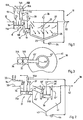
- la figure 1 est une vue schématique en élévation d'une première installation de traitement d'eau conforme à l'invention,
- la figure 2 est une vue schématique en élévation d'une seconde installation de traitement d'eau conforme à l'invention,
- la figure 3 est une vue schématique partielle de dessus de cette seconde installation,
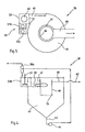
- la figure 4 est une vue schématique en élévation d'une troisième installation de traitement d'eau conforme à l'invention, et
- la figure 5 est une vue schématique de dessus de cette troisième installation.
- FIG. 1 is a schematic elevation view of a first water treatment installation according to the invention,
- FIG. 2 is a schematic elevation view of a second water treatment installation according to the invention,
- FIG. 3 is a partial schematic view from above of this second installation,
- FIG. 4 is a schematic elevation view of a third water treatment installation according to the invention, and
- Figure 5 is a schematic top view of this third installation.
La figure 1 représente de façon schématique une installation de traitement d'eau 10 comportant en série :
une première zone 11A dite zone de coagulation munie d'une voie principale d'arrivée 12 connectée à une source d'eau à traiter et d'une voiesecondaire 13 connectée à une source de réactif coagulant 13A,- au moins
un élément d'agitation 16 dans cette zone de coagulation, - une seconde zone dite zone intermédiaire communiquant avec
la première zone, ici par sousverse (la communication peut
bien sûr, en variante non représentée, se faire par surverse),
et connectée par des voies secondaires 14 et 15 respectivement,
à une
source 14A d'agent floculant et à unesource 15A de matériau granulaire insoluble dans l'eau et plus dense que l'eau, - au moins de seconds moyens d'agitation dans cette zone intermédiaire, relié à des moyens de mise en oeuvre aptes à la génération dans l'ensemble de cette zone de gradients de vitesse de l'ordre d'au moins 70 s-1 à 450 s-1 environ, de préférence de l'ordre de 150 à 250 s-1 environ,
- une troisième
zone 21 dite zone de décantation, communiquant avec la seconde zone (ici par surverse) et munie à sa partie supérieure d'une voie 22 de sortie pour de l'eau clarifiée et à sa partie inférieure d'une voie 23 d'évacuation de boues, ici munie d'un élément de pompage 24, - une zone de séparation constituant ici la
source 15A de matériau granulaire, apte à récupérer le matériau granulaire dans les boues et munie d'une voie de sortie de boues 15B et d'une voie de sortie 15C de matériau granulaire. Cette séparation peut se faire par tout moyen connu approprié à disposition de l'homme de métier pour séparer le sable recyclé des boues, notamment par hydrocyclonage, tamisage ou centrifugation.
- a
first zone 11A, called the coagulation zone, provided with amain inlet channel 12 connected to a source of water to be treated and asecondary channel 13 connected to a source of coagulatingreagent 13A, - at least one
agitation element 16 in this coagulation zone, - a second zone called the intermediate zone communicating with the first zone, here by underflow (communication can of course, in variant not shown, be done by overflow), and connected by
secondary channels source 14A of flocculating agent and at asource 15A of granular material insoluble in water and denser than water, - at least second stirring means in this intermediate zone, connected to implementation means suitable for generating throughout this zone speed gradients of the order of at least 70 s -1 to 450 s -1 approximately, preferably of the order of 150 to 250 s -1 approximately,
- a
third zone 21 known as the settling zone, communicating with the second zone (here by overflow) and provided at its upper part with anoutlet channel 22 for clarified water and at its lower part with a channel 23 ' sludge removal, here provided with apumping element 24, - a separation zone here constituting the
source 15A of granular material, capable of recovering the granular material in the sludge and provided with asludge outlet path 15B and anoutlet path 15C of granular material. This separation can be done by any suitable known means available to the skilled person to separate the recycled sand from the sludge, in particular by hydrocyclonage, sieving or centrifugation.
La zone ou chambre de décantation est ici de
section circulaire (elle peut être prévue de toute autre
forme, avec des trémies inférieures d'évacuation des boues)
et est avantageusement munie d'un racleur 25 longeant le fond
conique de cette zone et entraínée en rotation par un moteur
26 à une vitesse généralement lente, afin d'assurer en
pratique une vitesse périphérique inférieure ou égale à
10 cm/s environ.The settling zone or chamber is here
circular section (it can be provided for any other
shape, with lower sludge discharge hoppers)
and is advantageously provided with a
A la partie supérieure de la chambre de décantation
est prévue une goulotte 27 de récupération de l'eau
clarifiée.At the top of the settling chamber
a
Selon l'invention, la zone de décantation a une section de passage massive, c'est-à-dire ne présente pas d'éléments mécaniques subdivisant l'écoulement à l'approche de la voie de sortie de l'effluent clarifié. Il n'y a donc pas de lamelles dans la zone de décantation. Des éléments de répartition tels que cloisons ou goulottes de renvoi peuvent bien entendu être prévus à des fins de régulation hydraulique, en fonction de la géométrie de la zone de décantation.According to the invention, the settling zone has a massive passage section, i.e. does not have of mechanical elements dividing the flow on approach of the outlet for the clarified effluent. So there is no lamellae in the settling zone. Elements of distribution such as bulkheads or return ducts can of course be provided for hydraulic regulation purposes, depending on the geometry of the settling zone.
La chambre de décantation est pourtant dimensionnée par rapport à un débit nominal d'eau à traiter Q, en sorte que la "vitesse au miroir" Vm soit dans cette chambre d'au moins 15 m/h, de préférence d'au moins 35 m/h.The decantation chamber is however sized relative to a nominal flow of water to be treated Q, in so that the "mirror speed" Vm is in this room at least 15 m / h, preferably at least 35 m / h.
En d'autres termes, la chambre de décantation a
une section horizontale S telle que :
Le coagulant est de tout type connu approprié (par exemple chlorure ferrique ou sulfate d'aluminium).The coagulant is of any suitable known type (for example ferric chloride or aluminum sulfate).
La zone intermédiaire est ici formée de deux
chambres en série : une chambre de floculation 11B dans
laquelle débouchent la voie secondaire 14 d'arrivée d'agent
floculant et la voie secondaire 15 d'arrivée de matériau
granulaire, et une zone de maturation 18.The intermediate zone here is formed of two
chambers in series: an 11B flocculation chamber in
which lead to the
En variante non représentée, la zone de maturation
comporte une voie secondaire connectée à la source 14A,
permettant un ajout complémentaire d'agent floculant.In a variant not shown, the maturation zone
has a secondary channel connected to the
Cet agent floculant est de tout type connu approprié (notamment polyélectrolyte, de type anionique et/ou cationique). This flocculating agent is of any known type suitable (in particular polyelectrolyte, of anionic type and / or cationic).
En variante non représentée, la voie secondaire
15 d'arrivée de matériau granulaire débouche dans la zone
11A, ou même dans la chambre 18, voire dans plusieurs des
chambres 11A, 11B et 18. Il est préférable que ce matériau
granulaire soit injecté dans la chambre 11A et/ou dans la
chambre 11B.In a variant not shown, the
Les chambres 11A et 11B sont ici de tailles
similaires, au sein d'une batterie 11.The
Chacune des chambres 11B et 18 comporte un
agitateur, le gradient de vitesse étant en principe maximum
dans la zone de floculation. La chambre 11B comporte ainsi un
agitateur 17 adapté, grâce à un moteur non représenté, à
générer des gradients de vitesse compris entre 100 et 450 s-1,
de préférence entre 200 et 250 s-1, tandis que la chambre 18
comporte un agitateur 19 adapté, grâce à son moteur 20, à
générer des gradients de vitesse compris entre 70 et 300 s-1,
de préférence entre 150 et 200 s-1.Each of the
Le matériau granulaire est de préférence du sable (facile à obtenir et peu coûteux) de taille moyenne comprise entre 20 et 300 µm environ, de préférence entre 80 et 200 µm.The granular material is preferably sand (easy to obtain and inexpensive) with an average size of between 20 and 300 μm approximately, preferably between 80 and 200 μm .
Les figures 2 et 3 représentent une variante de
réalisation de l'invention. On y voit une installation 30
dont les éléments analogues à ceux de la figure 1 ont des
numéros de référence qui s'en déduisent par addition du
nombre 20.Figures 2 and 3 show a variant of
realization of the invention. We see an installation there 30
whose elements similar to those of FIG. 1 have
reference numbers which are deduced therefrom by adding the
La principale différence vis à vis de la figure
1 est que, si les zones de coagulation et de floculation sont
comme précédemment à l'extérieur de la zone 41, la zone de
maturation 38 est par contre au centre de cette zone 41 de
décantation en communiquant avec la zone de floculation par
un tube (ou une goulotte) descendant 45' ; en face de la
sortie de ce tube est prévue une cloison 46' destinée à
forcer une circulation vers la bas de la masse fluide,
jusqu'au fond de la chambre de maturation 38.The main difference from the figure
1 is that, if the coagulation and flocculation zones are
as before outside of
La masse fluide sort de cette chambre intermédiaire par surverse. The fluid mass leaves this intermediate chamber by overflow.
Pour éviter qu'une partie de la masse fluide ne
parte directement vers la voie de sortie 42, une cloison
tubulaire 47' est prévue autour de la chambre intermédiaire
en ayant son bord supérieur qui arrive plus haut que le
niveau normal de la masse fluide dans la chambre de décantation.To prevent part of the fluid mass from
goes directly to
Le fond conique de cette chambre de décantation est ici sans racleur, ce qui est rendu possible par l'inclinaison importante (supérieure typiquement à 55°) donnée à ce fond.The conical bottom of this settling chamber is here without scraper, which is made possible by the tilt important (typically greater than 55 °) given to this background.
La configuration de ces figures 2 et 3 a, par rapport à celle de la figure 1, l'avantage de pouvoir s'adapter de manière plus compacte à un ouvrage existant et de permettre une meilleure répartition dans la zone de décantation.The configuration of these Figures 2 and 3 a, by compared to that of FIG. 1, the advantage of being able adapt more compactly to an existing structure and to allow a better distribution in the area of decantation.
Les figures 4 et 5 représentent une autre
variante de réalisation de l'invention. On y voit une
installation 50 dont les éléments analogues à ceux de la
figure 1 ont des numéros de référence qui s'en déduisent par
addition du nombre 40.Figures 4 and 5 show another
variant embodiment of the invention. We see a
La principale différence vis à vis de la figure
1 réside dans le fait que la sortie de la chambre de maturation
58 est un tube 65 qui débouche latéralement dans la
chambre de décantation 61, à l'écart de, et transversalement
à son axe vertical de symétrie. Plus précisément, le tube 65
débouche avantageusement tangentiellement à la paroi latérale
de la chambre 61, ce qui provoque un effet de cyclone ou
vortex qui contribue à accélérer la décantation.The main difference from the figure
1 lies in the fact that the exit from the
Au centre de la chambre est prévue une paroi
tubulaire 66 sans fond au sommet de laquelle déborde par
surverse de l'eau clarifiée qui est recueillie par une rigole
annulaire 67 raccordée à une goulotte d'évacuation 68. En
variante, la paroi tubulaire 66 a un fond schématisé par la
ligne mixte 70, isolant hydrauliquement l'intérieur de cette
paroi vis à vis du reste du décanteur, et c'est vers l'intérieur
de cette paroi que déborde par surverse de l'eau
clarifiée avant de s'évacuer par la goulotte 62 qui, dans ce
cas, part directement de l'intérieur de cette paroi.In the center of the chamber is provided a bottomless
L'existence de deux chambres successives dans la zone intermédiaire des figures 1 à 5 s'explique par le fait qu'il est apparu que, dans le cas d'eaux chargées en matière organique colloïdale, un mode préféré de formation du floc pour obtenir une eau décantée de meilleure qualité consiste à injecter en tête de préparation l'agent coagulant destiné à déstabiliser la solution colloïdale (usuellement un sel de métal à valence élevée ou un polymère cationique), mélangé à l'eau brute par agitation ou par mélange statique. C'est après ce premier mélange déstabilisant que le polyélectrolyte floculant est injecté dans la zone de floculation agitée à gradient de vitesse assez élevé (entre 100 et 450 s-1, préférentiellement vers 200 s-1 environ), permettant aux microflocs résultant de la coagulation de se rencontrer et d'emprisonner des particules de matériau granulaire maintenues en suspension.The existence of two successive chambers in the intermediate zone of FIGS. 1 to 5 is explained by the fact that it has appeared that, in the case of water loaded with colloidal organic matter, a preferred mode of formation of the flock to obtain better quality decanted water consists in injecting at the head of the preparation the coagulating agent intended to destabilize the colloidal solution (usually a high valence metal salt or a cationic polymer), mixed with the raw water by stirring or by static mixing . It is after this first destabilizing mixture that the flocculating polyelectrolyte is injected into the agitated flocculation zone at a fairly high speed gradient (between 100 and 450 s -1 , preferably around 200 s -1 approximately), allowing the microflocs resulting from the coagulation to meet and trap particles of granular material kept in suspension.
Enfin, le mélange d'eau et de floc est introduit dans la chambre de maturation, agitée avec un gradient de vitesse d'environ 70 à 300 s-1 environ, préférentiellement de l'ordre de 150 s-1 environ. Dans la chambre de maturation, les flocs s'agrègent jusqu'à atteindre une taille optimum comprise, suivant la qualité d'eau entrante, entre 0,5 et 2,5 mm environ. Le temps de séjour dans la zone de coagulation peut être très faible, dépendant principalement de la qualité de mélange assurée dans cette zone (temps usuellement compris entre quelques secondes et 3 minutes voire plus (jusqu'à 10 minutes), préférentiellement 30 secondes à 1,5 minute au débit de pointe).Finally, the mixture of water and floc is introduced into the maturation chamber, agitated with a speed gradient of approximately 70 to 300 s -1 approximately, preferably of the order of approximately 150 s -1 . In the maturation chamber, the flocs aggregate until reaching an optimum size understood, depending on the quality of incoming water, between 0.5 and 2.5 mm approximately. The residence time in the coagulation zone can be very short, mainly depending on the quality of mixing ensured in this zone (time usually between a few seconds and 3 minutes or even more (up to 10 minutes), preferably 30 seconds to 1 , 5 minutes at peak flow).
Le temps de séjour dans la zone de floculation est avantageusement compris entre 0,5 et 4 minutes voire plus, jusqu'à 10 minutes (préférentiellement 1,5 à 2 minutes au débit de pointe) ; ; le temps de séjour dans la zone de maturation est compris entre 2 et 8 minutes voire plus, jusqu'à 15 minutes (préférentiellement 3 à 6 minutes au débit de pointe à traiter).The residence time in the flocculation zone is advantageously between 0.5 and 4 minutes or even more, up to 10 minutes (preferably 1.5 to 2 minutes at peak flow); ; residence time in the area of maturation is between 2 and 8 minutes or more, up to 15 minutes (preferably 3 to 6 minutes at flow peak).
On appréciera que la non-utilisation de lamelles dans la zone de décantation permet de s'affranchir des contraintes d'installation de ces lamelles. C'est ainsi notamment que l'on peut choisir une forme ronde pour les chambres de décantation.It will be appreciated that the non-use of slats in the settling zone allows to get rid of installation constraints of these slats. This is how especially that we can choose a round shape for settling chambers.
L'invention combine une préparation dans une série d'au moins 2 chambres (floculation et maturation, si la coagulation est préalablement réalisée en ligne) et préférentiellement 3 chambres (coagulation, floculation, maturation comme dans les exemples précités) ces cuves étant rectangulaires ou cylindriques, à une décantation simple dans une cuve rectangulaire ou cylindrique, en fonction des contraintes d'implantation ou de génie civil.The invention combines a preparation in a series of at least 2 chambers (flocculation and maturation, if the coagulation is carried out online beforehand) and preferably 3 chambers (coagulation, flocculation, maturation as in the above examples) these tanks being rectangular or cylindrical, with simple decantation in a rectangular or cylindrical tank, depending on the constraints of implantation or civil engineering.
Le mode de réalisation sans lamelles des figures 4 et 5 combine la préparation physico-chimique du floc lesté décrite ci-dessus avec une décantation améliorée dans un décanteur de type cyclone ou vortex.The embodiment without lamellae of the figures 4 and 5 combine the physico-chemical preparation of the weighted floc described above with improved settling in a cyclone or vortex decanter.
Ce type de décanteur a été testé en décantation naturelle et permet, sans recours aux lamelles, d'augmenter les vitesses au miroir possibles : son utilisation en combinaison avec une préparation physico-chimique soignée d'un floc lesté dense telle que décrite ci-dessus permet d'augmenter les performances de décantation par rapport à une décantation simple.This type of decanter has been tested in decantation natural and allows, without the use of slats, to increase possible mirror speeds: its use in combination with careful physico-chemical preparation a dense ballasted floc as described above allows increase the settling performance compared to a simple settling.
Une installation pilote a été réalisée de la manière suivante :
- cuve de floculation : 4 m3 fortement agités (~50 W/m3, soit un gradient de vitesse d'environ 220 s-1) dans lesquels on injecte du chlorure ferrique,
- cuve d'injection : 4 m3 également fortement agités (~ 50 W/m3, soit un gradient de vitesse d'environ 220 s-1) dans lesquels on injecte un polymère anionique et du sable de diamètre 130 µm issu de la sous-verse d'un hydrocyclone séparant les boues extraites du sable en recirculation ;
- cuve de maturation : 15 m3 agités plus lentement (~ 35 W/m3, soit un gradient de vitesse d'environ 190 s-1) ;
- cuve de décantation : section rectangulaire de 1,94 x 1,1 = 2,1 m2 (surface au miroir) sur une hauteur de 1,5 m alimentée frontalement par le bas et équipée d'une trémie pyramidale avec soutirage par chasse des boues et du sable ;
- récupération de l'eau traitée par une goulotte centrale de 0,5 m de large.
- flocculation tank: 4 m 3 strongly agitated (~ 50 W / m 3 , i.e. a speed gradient of approximately 220 s -1 ) into which ferric chloride is injected,
- injection tank: 4 m 3 also strongly agitated (~ 50 W / m 3 , i.e. a speed gradient of approximately 220 s -1 ) into which an anionic polymer and sand of diameter 130 μ m from the underflow of a hydrocyclone separating the sludge extracted from the recirculating sand;
- maturation tank: 15 m 3 agitated more slowly (~ 35 W / m 3 , i.e. a speed gradient of approximately 190 s -1 );
- decantation tank: rectangular section of 1.94 x 1.1 = 2.1 m 2 (surface in the mirror) over a height of 1.5 m supplied frontally from below and equipped with a pyramidal hopper with draw-off by flushing mud and sand;
- recovery of treated water by a central chute 0.5 m wide.
Le tableau suivant donne les résultats de deux
essais :
En fait l'essai 2 correspond, par rapport à l'essai 1, à un "fort" débit et une "faible" teneur en Matières En Suspension.In fact test 2 corresponds, compared to test 1, at a "high" flow rate and a "low" content Suspended matter.
On remarque à l'examen de ce tableau que d'excellents rendements d'abattement des MES sont obtenus avec des vitesses au miroir considérables (de 45 et 90 m/h).We observe on examining this table that excellent MES abatement yields are obtained with considerable mirror speeds (45 and 90 m / h).
Il va de soi que la description qui précède n'a été proposée qu'à titre d'exemple non limitatif et que de nombreuses variantes peuvent être proposées par l'homme de l'art sans sortir du cadre de l'invention. C'est ainsi notamment que l'invention se généralise au traitement de tout autre liquide chargé en particules ou colloïdes, tel que par exemple les bains pour traitement de surface des métaux dans le domaine de la métallurgie.It goes without saying that the above description does not has been proposed as a non-limiting example and that many variations can be proposed by the man of art without departing from the scope of the invention. This is how in particular that the invention is generalized to the treatment of any other liquid loaded with particles or colloids, such as example baths for surface treatment of metals in the field of metallurgy.
Claims (30)
- Method of treating an untreated flow of liquid charged with particles and/or colloids wherein:characterized in that the speed gradient in the intermediate zone is from 70 s-1 to 450 s-1, preferably from 150 s-1 to 250 s-1, and in that the sedimentation zone (21, 41, 61) in which the clarified effluent and the sludge are separated has no separator plates and the flow laden with granular material and with aggregated material is caused to flow therein at an average settling speed of at least 15 m/h.said untreated flow is caused to flow in a first or coagulation zone (11A, 31A, 51A) that is kept turbulent and in which said flow is mixed in controlled proportions with a coagulant reagent,the coagulated flow and a granular material added in controlled proportions and which is insoluble in and more dense than said flow are caused to flow in a second or intermediate zone (11B, 18, 31B, 38, 51B, 58) in which turbulence is maintained in order to maintain said granular material in suspension while colloids or particles in the flow aggregate around particles of said granular material,the flow with substantially all of the added granular material and the colloids or particles aggregated therein is caused to flow in a third or sedimentation zone (21, 41, 61) in which a clarified effluent is separated from sludge consisting of the granular material and the aggregated colloids,the sludge is collected, the granular material is extracted from it to recycle it and the sludge is extracted without granular material,
- Method according to claim 1 characterized in that the untreated flow is effluent.
- Method according to claim 1 characterized in that the settling speed is at least 35 m/h.
- Method according to any of claims 1 to 3 characterized in that the yield of materials in suspension is greater than 73.7%.
- Method according to any of claims 1 to 4, characterized in that the granular material is fine sand.
- Method according to claim 5 characterized in that the mean particle size of the sand is from approximately 20 µm to approximately 300 µm, preferably from 100 µm to 200 µm.
- Method according to any of claims 1 to 5 characterized in that a flocculant agent is fed into the untreated flow in a first part of the intermediate or flocculation zone (11B, 31B, 51B) which is kept turbulent, the remainder of the intermediate zone constituting a maturation zone in which aggregation of the particles and colloids is completed.
- Method according to claim 7 characterized in that further flocculant agent is fed into the maturation zone.
- Method according to claim 7 characterized in that at least some of the granular material is fed into the flocculation zone.
- Method according to any of claims 7 to 9 characterized in that the flocculation zone is stirred with a speed gradient from approximately 100 s-1 to approximately 450 s-1, preferably from 200 s-1 to 250 s-1.
- Method according to claim 10 characterized in that the speed gradient in the maturation zone (18, 38, 58) is less than the speed gradient in the flocculation zone.
- Method according to any of claims 7 to 11 characterized in that the speed gradient in the maturation zone is from 70 s-1 to 300 s-1, preferably from 150 s-1 to 200 s-1.
- Method according to any of claims 1 to 12 characterized in that a cyclone or vortex is generated in the sedimentation zone (61) by feeding the flow from the second zone from a predetermined side of a vertical axis of symmetry of said sedimentation zone.
- Method according to any of claims 1 to 13 characterized in that the granular material is separated from the sludge by hydrocycloning, screening or centrifuging.
- Installation for treating an untreated flow of liquid, including in series:characterized in that the stirrer means of the intermediate zone are connected to means adapted to generate by means of the stirrer means speed gradients from 70 s-1 to 450 s-1, preferably from 150 s-1 to 250 s-1, and in that the sedimentation zone has no separator plates and dimensions, given a predetermined inlet flowrate value, such that the average mirror speed therein is at least 15 m/h.a first coagulation zone (11A, 31A, 51A) having a main entry channel connected to a source of untreated flow and a secondary channel connected to a source of coagulant reagent,stirrer means (16, 36, 56) in said coagulation zone,a second or intermediate zone (18, 11B. 38, 31A, 58, 51A) communicating with the first zone,second stirrer means (20, 40, 60) in said intermediate zone,a secondary channel connected to a source of granular material that is insoluble in and more dense than said untreated flow, discharging into the coagulation zone or into the intermediate zone,a third or sedimentation zone (21, 41, 61) communicating with the second zone and having in its upper part an outlet channel for clarified effluent and in its lower part a sludge removal channel,a separation zone (15A, 35A, 55A) adapted to recover the granular material in the sludge and having an outlet channel connected to the source of granular material,
- Treatment installation according to claim 15 characterized in that the sedimentation zone has dimensions such that the mirror speed therein is at least 35 m/h.
- Treatment installation according to either of claims 15 and 16 characterized in that the yield of materials in suspension is greater than 73.7%.
- Treatment installation according to any of claims 15 to 17 characterized in that the intermediate zone includes a flocculation zone (11B, 31A, 51A) into which a coagulated flow inlet channel and a secondary inlet channel connected to a source of flocculant agent discharge, followed by a maturation zone (18, 38, 58).
- Treatment installation according to claim 18 characterized in that the maturation zone includes a flocculant agent inlet second channel.
- Treatment installation according to either of claims 18 and 19 characterized in that the secondary inlet channel connected to the source of granular material discharges into the flocculation zone.
- Treatment installation according to any of claims 18 to 20 characterized in that the second stirrer means in said intermediate zone are connected to means adapted to generate by means of said second stirrer means speed gradients in the flocculation zone from approximately 100 s-1 to approximately 450 s-1, preferably from 200 s-1 to 250 s-1, and speed gradients in the maturation zone from approximately 70 s-1 to approximately 300 s-1, preferably from 150 s-1 to 200 s-1.
- Treatment installation according to any of claims 15 to 21 characterized in that the sedimentation zone (21, 41, 61) is a circular cross-section chamber.
- Treatment installation according to any of claims 15 to 22 characterized in that the maturation zone (38) is a chamber at the centre of the sedimentation zone.
- Treatment installation according to claim 23 characterized in that the maturation zone i) is connected at its entry end to a downwardly extending tube (45), ii) contains a wall (46) in front of the outlet of said tube and adapted to be crossed by underflow, and iii) is surrounded by an upwardly projecting tubular wall (47), the outlet channel (42) for clarified effluent extending from the upper zone of the sedimentation zone to the exterior of said tubular wall.
- Treatment installation according to any of claims 15 to 22 characterized in that the maturation zone communicates with the sedimentation zone via a tube (65) discharging into the sedimentation zone away from a vertical axis of symmetry of the latter, so as to generate a cyclone or vortex.
- Treatment installation according to claim 25 characterized in that the sedimentation zone (61) is circular and the tube (65) discharges therein tangentially.
- Treatment installation according to claim 25 or 26 characterized in that the sedimentation zone (61) has in a central position a tubular wall (66) communicating with a clarified effluent removal trough (68).
- Treatment installation according to claim 27 characterized in that the tubular wall has no bottom and is bordered in its upper part by a gutter (67) communicating with the trough (68).
- Treatment installation according to claim 27 characterized in that the tubular wall has a bottom (70) hydraulically isolating the interior of said tubular wall from the remainder of the sedimentation device and communicating with the removal trough.
- Treatment installation according to any of claims 15 to 29 characterized in that the separation zone includes at least one hydrocyclone, screen, centrifuge or equivalent sand/sludge separator means.
Applications Claiming Priority (2)
| Application Number | Priority Date | Filing Date | Title |
|---|---|---|---|
| FR9405308A FR2719234B1 (en) | 1994-05-02 | 1994-05-02 | Method and installation for treating a raw flow by simple decantation after ballasting with fine sand. |
| FR9405308 | 1994-05-02 |
Publications (2)
| Publication Number | Publication Date |
|---|---|
| EP0680933A1 EP0680933A1 (en) | 1995-11-08 |
| EP0680933B1 true EP0680933B1 (en) | 2001-12-12 |
Family
ID=9462734
Family Applications (1)
| Application Number | Title | Priority Date | Filing Date |
|---|---|---|---|
| EP95400873A Expired - Lifetime EP0680933B1 (en) | 1994-05-02 | 1995-04-19 | Process and plant for the treatment of a raw fluid flow by simple settlement after introducing fine sand |
Country Status (8)
| Country | Link |
|---|---|
| US (1) | US5730864A (en) |
| EP (1) | EP0680933B1 (en) |
| JP (1) | JP3641008B2 (en) |
| CA (1) | CA2148039C (en) |
| DE (1) | DE69524473T2 (en) |
| DK (1) | DK0680933T3 (en) |
| FR (1) | FR2719234B1 (en) |
| TR (1) | TR29002A (en) |
Families Citing this family (49)
| Publication number | Priority date | Publication date | Assignee | Title |
|---|---|---|---|---|
| FR2739094B1 (en) * | 1995-09-21 | 1997-12-19 | Omnium Traitement Valorisa | PROCESS AND PLANT FOR DESSABLING AND PHYSICO-CHEMICAL DECANTATION OF URBAN OR INDUSTRIAL EFFLUENTS |
| US5800717A (en) * | 1996-10-02 | 1998-09-01 | Microsep International Corporation | Water and wastewater treatment system with internal recirculation |
| FR2758812B1 (en) * | 1997-01-27 | 1999-07-09 | Degremont | PROCESS FOR THE PHYSICO-CHEMICAL TREATMENT OF EFFLUENTS, IN PARTICULAR SURFACE WATER INTENDED FOR CONSUMPTION |
| DE69802781T2 (en) * | 1997-01-27 | 2002-05-23 | Degremont, Rueil-Malmaison | METHOD FOR THE PHYSICAL-CHEMICAL TREATMENT OF WATER, IN PARTICULAR SURFACE WATER INTENDED FOR CONSUMPTION |
| FR2769613A1 (en) * | 1997-10-14 | 1999-04-16 | Omnium Traitement Valorisa | Water purification with two stage thickening of sludge |
| US6083404A (en) * | 1998-09-18 | 2000-07-04 | Nalco Chemical Company | Method of dewatering difficult sludges |
| JP3901391B2 (en) * | 1999-05-13 | 2007-04-04 | オルガノ株式会社 | Coagulation sedimentation equipment |
| JP2001120909A (en) * | 1999-10-21 | 2001-05-08 | Japan Organo Co Ltd | Flocculating and settling device |
| FR2801878B1 (en) * | 1999-12-03 | 2002-02-22 | Degremont | METHOD AND PLANT FOR CLARIFYING LIQUIDS AND SUSPENSIONS BY MEASURED FLOCCULATION AND DECANTATION |
| US6890431B1 (en) * | 2000-02-18 | 2005-05-10 | The F. B. Leopold Co., Inc. | Buoyant media flotation |
| FR2810898B1 (en) * | 2000-06-29 | 2002-09-27 | Amenagement Urbain & Rural | WATER TREATMENT PROCESS AND DEVICE WITH INJECTED BALLAST IN A TRANQUILIZED AREA |
| US6383370B1 (en) | 2000-09-14 | 2002-05-07 | Infilco Degremont Inc. | Apparatus for treating wastewater |
| FR2815714B1 (en) * | 2000-10-20 | 2003-01-03 | Omnium Traitement Valorisa | INSTALLATION FOR MEASURING THE CONCENTRATION OF GRANULAR MATERIAL DENSE OF A FLOW AND SYSTEM FOR THE TREATMENT OF WATER INCLUDING SUCH AN INSTALLATION |
| AU2002220093B2 (en) | 2000-11-02 | 2006-09-14 | Veolia Water Solutions & Technologies Support | Method and apparatus for treatment of water and wastewater |
| FR2822080B1 (en) | 2001-03-15 | 2004-10-29 | Vivendi Water Systems | PROCESS AND PLANT FOR TREATING WATER BY MEASURED FLOCCULATION AND GRAVITY SEPARATION WITH VARIABLE MODE OF OPERATION |
| US20030150817A1 (en) * | 2002-02-11 | 2003-08-14 | Keever Christopher S. | Method and apparatus for treating wastewater |
| US6517714B2 (en) | 2001-04-30 | 2003-02-11 | Parkson Corporation | Treatment of liquids with ballasted flocculation |
| JP4535419B2 (en) * | 2001-05-31 | 2010-09-01 | オルガノ株式会社 | Coagulation sedimentation equipment |
| US6607671B2 (en) * | 2001-08-15 | 2003-08-19 | Texaco Inc. | Reactor and solids settler for grey water treatment |
| FR2833939B1 (en) | 2001-12-21 | 2004-10-29 | Omnium Traitement Valorisa | METHOD OF TREATING WATER BY DEACTED FLOCCULATION AND DECANTATION |
| EP1478467A1 (en) * | 2002-02-25 | 2004-11-24 | John Meunier Inc. | Acoustic sensor for obstruction in a device circulating vortex-flow fluid |
| FR2863908B1 (en) * | 2003-12-22 | 2006-05-19 | Otv Sa | FLOCCULATION TREATMENT PROCESS AND REACTOR |
| US20060108273A1 (en) * | 2004-02-06 | 2006-05-25 | Perri Joyce S | Ballasted flocculation process and system incorporating an electro-coagulation reactor for treating water or wastewater |
| FR2891540B1 (en) * | 2005-09-30 | 2007-12-28 | Otv Sa | METHOD FOR TREATING WATER COMPRISING A RAPID DECANTATION STEP FOLLOWED BY A FILTRATION STEP DIRECTLY ON MEMBRANES OF MICRO OR ULTRA-FILTRATION, AND CORRESPONDING DEVICE |
| US7695630B2 (en) * | 2005-11-15 | 2010-04-13 | De Guevara Cesar Ladron | Process for conditioning an aqueous solution for efficient colloidal precipitation |
| FR2904621B1 (en) * | 2006-08-01 | 2011-04-01 | Otv Sa | WATER TREATMENT PROCESS BY FLOCATION-DECANTATION COMPRISING A LEST CONTINUOUS MEASUREMENT AND CORRESPONDING INSTALLATION |
| FR2910822B1 (en) | 2006-12-29 | 2009-02-27 | Otv Sa | METHOD AND INSTALLATION FOR WATER TREATMENT THROUGH FLOCCULATION AND DECANTATION |
| EP2104649B1 (en) * | 2007-01-09 | 2018-09-19 | Evoqua Water Technologies LLC | System and method for enhancing an activated sludge process |
| US20100213123A1 (en) | 2007-01-09 | 2010-08-26 | Marston Peter G | Ballasted sequencing batch reactor system and method for treating wastewater |
| CA2675018C (en) | 2007-01-09 | 2012-06-05 | Cambridge Water Technology, Inc. | A system and method for removing dissolved contaminants, particulate contaminants, and oil contaminants from industrial waste water |
| US8470172B2 (en) | 2007-01-09 | 2013-06-25 | Siemens Industry, Inc. | System for enhancing a wastewater treatment process |
| US20110036771A1 (en) | 2007-01-09 | 2011-02-17 | Steven Woodard | Ballasted anaerobic system and method for treating wastewater |
| SE532693C2 (en) | 2007-03-29 | 2010-03-16 | Wo R Ld Consulting Ab | dewatering |
| US7608190B1 (en) | 2008-11-14 | 2009-10-27 | N.A. Water Systems, LLC | Process for removing barium from water |
| US7648637B1 (en) * | 2009-01-29 | 2010-01-19 | Otv S.A. | Water treatment method by ballasted flocculation, settling, and prior adsorbent contact |
| FR2958927B1 (en) * | 2010-04-20 | 2012-05-25 | Otv Sa | METHOD FOR WATER TREATMENT BY FLOCCULATION USING A FLOCCULANT AGENT OF NATURAL ORIGIN |
| JP5767009B2 (en) * | 2011-04-27 | 2015-08-19 | 水ing株式会社 | Method for starting up high-speed coagulation sedimentation basin and high-speed coagulation sedimentation apparatus for realizing |
| JP5826545B2 (en) * | 2011-07-20 | 2015-12-02 | 株式会社西原環境 | Polluted water treatment system and polluted water treatment method |
| JP5949059B2 (en) * | 2011-07-28 | 2016-07-06 | 栗田工業株式会社 | Solid-liquid separator |
| EP2858954A1 (en) | 2012-06-11 | 2015-04-15 | Evoqua Water Technologies LLC | Treatment using fixed film processes and ballasted settling |
| AU2013323431B2 (en) | 2012-09-26 | 2017-10-12 | Evoqua Water Technologies Llc | System for measuring the concentration of magnetic ballast in a slurry |
| US11291931B2 (en) | 2014-12-15 | 2022-04-05 | Akadeum Life Sciences, Inc. | Method and system for buoyant separation |
| JP6763806B2 (en) * | 2017-03-01 | 2020-09-30 | オルガノ株式会社 | Coagulation sedimentation device and its driving method |
| WO2020014273A1 (en) | 2018-07-09 | 2020-01-16 | Akadeum Life Sciences, Inc. | System and method for buoyant particle processing |
| CN109292931A (en) * | 2018-11-05 | 2019-02-01 | 黑河学院 | A wastewater discharge treatment device for solar cell preparation |
| EP4392158A4 (en) | 2021-08-26 | 2025-09-03 | Akadeum Life Sciences Inc | METHOD AND SYSTEM FOR FLOATING SEPARATION |
| US20230072021A1 (en) * | 2021-09-07 | 2023-03-09 | Steven L. Cort | Treatment of wastewater |
| EP4504367A1 (en) | 2022-04-01 | 2025-02-12 | Akadeum Life Sciences, Inc. | Method and system for buoyant-particle-assisted cell therapy |
| EP4646244A1 (en) | 2023-02-14 | 2025-11-12 | Akadeum Life Sciences, Inc. | Method and system for partially or fully automated buoyancy-assisted separation |
Family Cites Families (12)
| Publication number | Priority date | Publication date | Assignee | Title |
|---|---|---|---|---|
| FR1411792A (en) * | 1964-08-04 | 1965-09-24 | Nikex Nehezipari Kulkere | Process for clarifying and purifying surface water and industrial water containing suspended matter |
| FR1501912A (en) * | 1966-09-28 | 1967-11-18 | Pour Le Traitement Et L Utilis | Process applicable in particular to the clarification of water laden with impurities |
| FR2071027A6 (en) * | 1969-12-16 | 1971-09-17 | Traitement Utilisat Eaux | Water clarification process - using a fluidised bed |
| DE7138603U (en) * | 1971-10-12 | 1972-06-15 | Passavant Werke | Device for mechanical-chemical water treatment and wastewater treatment |
| JPS51142860A (en) * | 1975-04-30 | 1976-12-08 | Dowa Mining Co Ltd | Method for oxidation treatment of fe2+ in waste liquor |
| US4320012A (en) * | 1979-01-22 | 1982-03-16 | Palm Gordon F | Neutralization of phosphoric acid waste waters |
| US4388195A (en) * | 1979-07-05 | 1983-06-14 | Passavant-Werke Michelbacher Hutte | Process and apparatus for the chemical-mechanical treatment and purification of ground waters, surface waters and effluents |
| US4465597B2 (en) * | 1981-08-10 | 1997-07-01 | Tetra Tech | Treatment of industrial wastewaters |
| FR2553082B1 (en) * | 1983-10-07 | 1987-08-28 | Degremont | APPARATUS FOR TREATING WATER BY PRECIPITATION, SEPARATION, THICKENING AND RECIRCULATION OF FORMED SLUDGE |
| AT385498B (en) * | 1986-08-29 | 1988-04-11 | Cordt Gerhard Dipl Ing Dr | Wastewater treatment plant |
| FR2627704B1 (en) * | 1988-02-25 | 1991-12-13 | Ile France Syndicat Eaux | METHOD AND PLANT FOR TREATMENT OF WATER BY DECANTATION USING FINE SAND |
| US5112499A (en) * | 1991-05-22 | 1992-05-12 | Freeport-Mcmoran Resource Partners, Limited Partnership | Process for treating pond water |
-
1994
- 1994-05-02 FR FR9405308A patent/FR2719234B1/en not_active Expired - Fee Related
-
1995
- 1995-04-19 DE DE69524473T patent/DE69524473T2/en not_active Expired - Lifetime
- 1995-04-19 EP EP95400873A patent/EP0680933B1/en not_active Expired - Lifetime
- 1995-04-19 DK DK95400873T patent/DK0680933T3/en active
- 1995-04-27 CA CA002148039A patent/CA2148039C/en not_active Expired - Fee Related
- 1995-05-01 US US08/431,833 patent/US5730864A/en not_active Expired - Lifetime
- 1995-05-01 JP JP10761595A patent/JP3641008B2/en not_active Expired - Fee Related
- 1995-05-02 TR TR00509/95A patent/TR29002A/en unknown
Also Published As
| Publication number | Publication date |
|---|---|
| JP3641008B2 (en) | 2005-04-20 |
| FR2719234A1 (en) | 1995-11-03 |
| DK0680933T3 (en) | 2002-04-08 |
| JPH0847606A (en) | 1996-02-20 |
| US5730864A (en) | 1998-03-24 |
| EP0680933A1 (en) | 1995-11-08 |
| CA2148039A1 (en) | 1995-11-03 |
| FR2719234B1 (en) | 1999-08-13 |
| CA2148039C (en) | 2004-01-27 |
| TR29002A (en) | 1997-07-21 |
| DE69524473D1 (en) | 2002-01-24 |
| DE69524473T2 (en) | 2002-08-14 |
Similar Documents
| Publication | Publication Date | Title |
|---|---|---|
| EP0680933B1 (en) | Process and plant for the treatment of a raw fluid flow by simple settlement after introducing fine sand | |
| EP0330582B1 (en) | Method and device for the treatment of water by settlement introducing fine sand | |
| EP2108005B1 (en) | Method and plant for processing water by ballasted flocculation and deposition | |
| EP1483210B1 (en) | Method and device for clarification of liquids, particularly water, loaded with material in suspension | |
| FR2739094A1 (en) | METHOD AND INSTALLATION FOR DESSAVING AND PHYSICO-CHEMICAL DECANTATION OF URBAN OR INDUSTRIAL EFFLUENTS | |
| EP1991504B1 (en) | Plant and method for water treatment by flocculation/settling using ballasted floc with final degritting of the sludge | |
| EP2632859A1 (en) | Method for separating liquid from suspended matter in a sludge and device for same | |
| EP3094393B1 (en) | Method and device for treating liquid sludge and filter cakes obtained by said method | |
| CA1276325C (en) | Two-stage clarification process and device for liquids containing solids | |
| FR2922123A1 (en) | INSTALLATION FOR FLOCCULATION OF SUSPENDED MATERIAL SLUDGE, METHOD USING THE INSTALLATION | |
| FR3013700A1 (en) | METHOD AND DEVICE FOR TREATING LIQUID SLUDGE, AND SLATE GALVATES OBTAINED WITH SUCH A METHOD | |
| EP2632860A1 (en) | Water clarification method and device | |
| EP1294643B1 (en) | Method and device for treating water with ballast injected in stilling zone | |
| EP0174232B1 (en) | Method of clarifying a solids-loaden liquid by means of a sludge blanket | |
| FR2941225A1 (en) | COATING DEVICE WITH FLOCCULATING POLYMERIC MATERIAL IN THE LIQUID CONDITION OF BALLAST GRAINS USED FOR THE TREATMENT OF WATER BY FLOCCULATING THE SAME, AND CORRESPONDING INSTALLATION. | |
| EP2800730B1 (en) | Coagulation/flocculation apparatus for the treatment of a hydraulic flow, and implementation process | |
| WO2009130299A1 (en) | Hydrocyclone fluid treatment process | |
| JP4514958B2 (en) | Tangential solid separator | |
| WO2017033160A1 (en) | Method for treating waste water comprising a quick static decanter and associated facility | |
| FR2990212A1 (en) | PROCESS FOR RECOVERING HYDROCARBONS FROM A SLUDGE AND DEVICE USING SUCH A METHOD | |
| WO2024038163A1 (en) | Method for treating dirty overflow water from a water treatment plant, and corresponding facility | |
| BE481250A (en) | ||
| BE472960A (en) |
Legal Events
| Date | Code | Title | Description |
|---|---|---|---|
| PUAI | Public reference made under article 153(3) epc to a published international application that has entered the european phase |
Free format text: ORIGINAL CODE: 0009012 |
|
| AK | Designated contracting states |
Kind code of ref document: A1 Designated state(s): BE DE DK FR GB IT NL SE |
|
| 17P | Request for examination filed |
Effective date: 19951220 |
|
| 17Q | First examination report despatched |
Effective date: 19971205 |
|
| 18D | Application deemed to be withdrawn |
Effective date: 19990602 |
|
| 18RA | Request filed for re-establishment of rights before grant |
Effective date: 19991025 |
|
| 18RR | Decision to grant the request for re-establishment of rights before grant |
Free format text: 19991124 ANGENOMMEN |
|
| RIN1 | Information on inventor provided before grant (corrected) |
Inventor name: BINOT, PATRICK Inventor name: LE PODER, NICOLAS Inventor name: DELSALLE, FRANCOISE |
|
| GRAG | Despatch of communication of intention to grant |
Free format text: ORIGINAL CODE: EPIDOS AGRA |
|
| GRAG | Despatch of communication of intention to grant |
Free format text: ORIGINAL CODE: EPIDOS AGRA |
|
| GRAG | Despatch of communication of intention to grant |
Free format text: ORIGINAL CODE: EPIDOS AGRA |
|
| GRAH | Despatch of communication of intention to grant a patent |
Free format text: ORIGINAL CODE: EPIDOS IGRA |
|
| GRAH | Despatch of communication of intention to grant a patent |
Free format text: ORIGINAL CODE: EPIDOS IGRA |
|
| GRAA | (expected) grant |
Free format text: ORIGINAL CODE: 0009210 |
|
| AK | Designated contracting states |
Kind code of ref document: B1 Designated state(s): BE DE DK FR GB IT NL SE |
|
| REF | Corresponds to: |
Ref document number: 69524473 Country of ref document: DE Date of ref document: 20020124 |
|
| RAP2 | Party data changed (patent owner data changed or rights of a patent transferred) |
Owner name: OTV SA |
|
| NLT2 | Nl: modifications (of names), taken from the european patent patent bulletin |
Owner name: OTV SA |
|
| REG | Reference to a national code |
Ref country code: DK Ref legal event code: T3 |
|
| GBT | Gb: translation of ep patent filed (gb section 77(6)(a)/1977) |
Effective date: 20020418 |
|
| PLBE | No opposition filed within time limit |
Free format text: ORIGINAL CODE: 0009261 |
|
| STAA | Information on the status of an ep patent application or granted ep patent |
Free format text: STATUS: NO OPPOSITION FILED WITHIN TIME LIMIT |
|
| 26N | No opposition filed | ||
| REG | Reference to a national code |
Ref country code: NL Ref legal event code: TD Effective date: 20110621 |
|
| REG | Reference to a national code |
Ref country code: DE Ref legal event code: R082 Ref document number: 69524473 Country of ref document: DE Representative=s name: MEISSNER BOLTE PATENTANWAELTE RECHTSANWAELTE P, DE Effective date: 20110803 Ref country code: DE Ref legal event code: R082 Ref document number: 69524473 Country of ref document: DE Representative=s name: MEISSNER, BOLTE & PARTNER GBR, DE Effective date: 20110803 Ref country code: DE Ref legal event code: R081 Ref document number: 69524473 Country of ref document: DE Owner name: VEOLIA WATER SOLUTIONS & TECHNOLOGIES SUPPORT, FR Free format text: FORMER OWNER: OTV S.A., SAINT-MAURICE, FR Effective date: 20110803 Ref country code: DE Ref legal event code: R081 Ref document number: 69524473 Country of ref document: DE Owner name: VEOLIA WATER SOLUTIONS & TECHNOLOGIES SUPPORT, FR Free format text: FORMER OWNER: VEOLIA WATER SOLUTIONS & TECHNOLOGIES SUPPORT, SAINT-MAURICE, FR Effective date: 20110803 |
|
| REG | Reference to a national code |
Ref country code: FR Ref legal event code: CJ Effective date: 20111109 Ref country code: FR Ref legal event code: CD Owner name: VEOLIA WATER SOLUTIONS & TECHNOLOGIES SUPPORT, FR Effective date: 20111109 |
|
| PGFP | Annual fee paid to national office [announced via postgrant information from national office to epo] |
Ref country code: DK Payment date: 20120323 Year of fee payment: 18 |
|
| PGFP | Annual fee paid to national office [announced via postgrant information from national office to epo] |
Ref country code: NL Payment date: 20120326 Year of fee payment: 18 Ref country code: DE Payment date: 20120416 Year of fee payment: 18 Ref country code: BE Payment date: 20120430 Year of fee payment: 18 |
|
| PGFP | Annual fee paid to national office [announced via postgrant information from national office to epo] |
Ref country code: GB Payment date: 20120423 Year of fee payment: 18 Ref country code: FR Payment date: 20120529 Year of fee payment: 18 Ref country code: SE Payment date: 20120423 Year of fee payment: 18 |
|
| PGFP | Annual fee paid to national office [announced via postgrant information from national office to epo] |
Ref country code: IT Payment date: 20120423 Year of fee payment: 18 |
|
| BERE | Be: lapsed |
Owner name: VEOLIA WATER SOLUTIONS & TECHNOLOGIES SUPPORT S.A. Effective date: 20130430 |
|
| REG | Reference to a national code |
Ref country code: NL Ref legal event code: V1 Effective date: 20131101 |
|
| REG | Reference to a national code |
Ref country code: SE Ref legal event code: EUG |
|
| REG | Reference to a national code |
Ref country code: DK Ref legal event code: EBP Effective date: 20130430 |
|
| GBPC | Gb: european patent ceased through non-payment of renewal fee |
Effective date: 20130419 |
|
| PG25 | Lapsed in a contracting state [announced via postgrant information from national office to epo] |
Ref country code: DE Free format text: LAPSE BECAUSE OF NON-PAYMENT OF DUE FEES Effective date: 20131101 Ref country code: BE Free format text: LAPSE BECAUSE OF NON-PAYMENT OF DUE FEES Effective date: 20130430 Ref country code: SE Free format text: LAPSE BECAUSE OF NON-PAYMENT OF DUE FEES Effective date: 20130420 Ref country code: GB Free format text: LAPSE BECAUSE OF NON-PAYMENT OF DUE FEES Effective date: 20130419 |
|
| REG | Reference to a national code |
Ref country code: FR Ref legal event code: ST Effective date: 20131231 |
|
| REG | Reference to a national code |
Ref country code: DE Ref legal event code: R119 Ref document number: 69524473 Country of ref document: DE Effective date: 20131101 |
|
| PG25 | Lapsed in a contracting state [announced via postgrant information from national office to epo] |
Ref country code: IT Free format text: LAPSE BECAUSE OF NON-PAYMENT OF DUE FEES Effective date: 20130419 Ref country code: NL Free format text: LAPSE BECAUSE OF NON-PAYMENT OF DUE FEES Effective date: 20131101 Ref country code: FR Free format text: LAPSE BECAUSE OF NON-PAYMENT OF DUE FEES Effective date: 20130430 |
|
| PG25 | Lapsed in a contracting state [announced via postgrant information from national office to epo] |
Ref country code: DK Free format text: LAPSE BECAUSE OF NON-PAYMENT OF DUE FEES Effective date: 20130430 |