EP0680903A1 - Media sheet pick and feed system - Google Patents
Media sheet pick and feed system Download PDFInfo
- Publication number
- EP0680903A1 EP0680903A1 EP95302416A EP95302416A EP0680903A1 EP 0680903 A1 EP0680903 A1 EP 0680903A1 EP 95302416 A EP95302416 A EP 95302416A EP 95302416 A EP95302416 A EP 95302416A EP 0680903 A1 EP0680903 A1 EP 0680903A1
- Authority
- EP
- European Patent Office
- Prior art keywords
- pick
- pick roller
- media sheet
- roller shaft
- rotation
- Prior art date
- Legal status (The legal status is an assumption and is not a legal conclusion. Google has not performed a legal analysis and makes no representation as to the accuracy of the status listed.)
- Granted
Links
- 230000008878 coupling Effects 0.000 claims 2
- 238000010168 coupling process Methods 0.000 claims 2
- 238000005859 coupling reaction Methods 0.000 claims 2
- 230000037431 insertion Effects 0.000 claims 1
- 238000003780 insertion Methods 0.000 claims 1
- 238000013459 approach Methods 0.000 description 2
- 238000012986 modification Methods 0.000 description 2
- 230000004048 modification Effects 0.000 description 2
- 230000003068 static effect Effects 0.000 description 2
- 230000007423 decrease Effects 0.000 description 1
- 230000003247 decreasing effect Effects 0.000 description 1
- 238000010586 diagram Methods 0.000 description 1
- 230000000694 effects Effects 0.000 description 1
- 239000000463 material Substances 0.000 description 1
- 230000003287 optical effect Effects 0.000 description 1
Images

Classifications
-
- B—PERFORMING OPERATIONS; TRANSPORTING
- B65—CONVEYING; PACKING; STORING; HANDLING THIN OR FILAMENTARY MATERIAL
- B65H—HANDLING THIN OR FILAMENTARY MATERIAL, e.g. SHEETS, WEBS, CABLES
- B65H3/00—Separating articles from piles
- B65H3/02—Separating articles from piles using friction forces between articles and separator
- B65H3/06—Rollers or like rotary separators
- B65H3/0684—Rollers or like rotary separators on moving support, e.g. pivoting, for bringing the roller or like rotary separator into contact with the pile
-
- B—PERFORMING OPERATIONS; TRANSPORTING
- B65—CONVEYING; PACKING; STORING; HANDLING THIN OR FILAMENTARY MATERIAL
- B65H—HANDLING THIN OR FILAMENTARY MATERIAL, e.g. SHEETS, WEBS, CABLES
- B65H3/00—Separating articles from piles
- B65H3/02—Separating articles from piles using friction forces between articles and separator
- B65H3/06—Rollers or like rotary separators
- B65H3/0615—Rollers or like rotary separators reciprocating and rotatable in one direction only
-
- B—PERFORMING OPERATIONS; TRANSPORTING
- B65—CONVEYING; PACKING; STORING; HANDLING THIN OR FILAMENTARY MATERIAL
- B65H—HANDLING THIN OR FILAMENTARY MATERIAL, e.g. SHEETS, WEBS, CABLES
- B65H3/00—Separating articles from piles
- B65H3/02—Separating articles from piles using friction forces between articles and separator
- B65H3/06—Rollers or like rotary separators
- B65H3/0669—Driving devices therefor
Definitions
- This invention relates to media sheet feeders, and more particularly, to a media sheet pick and feed system that obviates the need for a spring loaded media sheet tray and enables easy re-loading of a media sheet tray.
- a commonly used prior art mechanism for picking and feeding of media sheets employs a D-shaped wheel which is rotated to cause a media sheet pick action.
- the flat section of the D-wheel remains out-of-contact with the fed sheet.
- This arrangement is satisfactory so long as the media sheet, during a feed operation, is not bent around the D-wheel shaft. This may occur when the media tray is positioned at an angle to the feed mechanism. Under such a circumstance, the media sheet must bend as it is fed into the print mechanism. If the media sheet presses against the D-shaped wheel, significant drag on the media sheet results.
- a solution to this problem has been to affix a pair of free-wheeling disks to the same shaft on which the D-wheel is mounted.
- FIG. 1 is a side view of the Epson pick wheel and comprises a drive gear 10 that is mounted on a shaft 12 which is, in turn, coupled to a drive motor (not shown).
- a pivot arm 14 is mounted for rotation about shaft 12 and encloses a rubber pick roller 16.
- a driven gear 18 mates with drive gear 10, is rigidly connected to rubber pick roller 16, and is mounted for rotation on a shaft 20.
- a spring washer 22 is positioned between an inner surface of arm 14 and driven gear 18 and performs a friction clutch function.
- a media tray includes a pressure plate 24 which supports a stack of media sheets 26 and is biased by a spring 28 into contact with rubber pick roller 16.
- An edge separator 30 is positioned to maintain an uppermost sheet on stack 26 in place until operation of rubber pick roller 16.
- drive gear 10 is driven in a counter clockwise (CCW) direction thereby causing driven gear 18 to rotate in a clockwise (CW) direction.
- CW clockwise
- arm 14 and pick roller 16 are caused to rotate in a CCW direction until arm 14 hits a stop 32.
- This action causes pick roller 16 to come into contact with an uppermost sheet of stack 26, which uppermost sheet is, in turn, forced against pick roller 16 through the action of spring 28 on tray 24.
- Continued clockwise rotation of pick roller 16 causes a feed of an uppermost sheet 34 from stack 26.
- the use of a spring loaded tray may require that the media sheet tray be removed for media sheet reloading or that a camming mechanism be provided that depresses the pressure plate to enable reloading.
- the camming mechanism increases torque requirements on the mechanism drive motor.
- a media sheet pick and feed system includes a pick roller shaft that is mounted for rotation and a media sheet tray which supports a stack of media sheets on a support surface. The support surface is separated from the pick roller shaft by a fixed distance during pick operations.
- An arm structure is coupled to and extends from the pick roller shaft and includes a pick roller that is geared to the pick roller shaft.
- a drive motor having first and second directions of rotation is coupleable via a clutch to the pick roller shaft. During a driven state, the drive motor, through the clutch, causes the pick roller shaft to rotate and operate the pick roller.
- the clutch mechanism in the non-driven state is uncoupled from the pick roller shaft and enables the pick roller to free wheel while it still remains in contact with a media sheet being fed. The pick roller is never out of contact with media sheets supported by the media sheet tray.
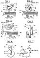
- Fig. 1 is a side view of a prior art pick roller mechanism.
- Fig. 2 is a schematic side view of the pick roller mechanism of Fig. 1 during a pick action.
- Fig. 3 is a schematic side view of the pick roller mechanism of Fig. 1 after the pick action and during a sheet feed.
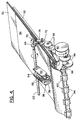
- Fig. 4 is a perspective view of a media sheet pick and feed system incorporating the invention hereof and illustrating a pick action.
- Fig. 5 is a front view of a clutch mechanism employed to drive a pick roller shaft in the system of Fig. 4.
- Fig. 6 is a side view of the clutch mechanism shown in Fig. 5.
- Fig. 7 is a force diagram illustrating a force feedback action which occurs during the operation of the pick roller shown in Fig. 4.
- Fig. 8 is a perspective view of the mechanism of Fig. 4 after a pick action has been accomplished and when a media sheet is being fed by feed rollers.
- a stack of media sheets 50 is supported on a tray 52 which is slidably removable from and insertable into a print mechanism. Tray 52 may be replenished with media sheets without removal from the print mechanism. Tray 52, when in position within the print mechanism, rests in a stationary position and includes no spring means for biasing stack 50 against the picking and feeding apparatus.
- a pair of arms 58 and 60 extend from and are mounted for rotation about a pick roller shaft 62. Arms 58 and 60 are connected (not shown) so as to always move in tandem.
- a pick roller drive gear 64 is rigidly mounted to pick roller shaft 62 and, through a pair of idler rollers 66, engages a gear (not shown) that is rigidly coupled to pick roller 56. Arms 58 and 60 enable pick roller 56 to rest on the topmost media sheet 54 of stack 50.
- the outer surface of pick roller 56 is preferably comprised of a rubber or a rubber-like material. As the size of stack 50 either increases or decreases, arms 58 and 60 rotate about pick roller shaft 62 and maintain pick roller 56 in constant contact with an uppermost sheet 54.
- a drive gear 68 that engages a friction clutch mechanism comprising gears 70, 72 and arm 74.
- a side view of the clutch mechanism (as seen from below tray 52) is shown in Fig. 5 and a plan view in Fig. 6.
- Gear 72 is mounted on a shaft 76 that extends from a fixed wall position (not shown) in Fig. 4.
- Gear 70 is connected to arm 74 via a shaft 78.
- a spring 80 is positioned between gear 70 and arm 74 so as to provide a frictional clutching operation.
- a motor 90 when driven CCW, operates through idler gears 92 to drive gear 72 in a CCW direction.
- Gear 70 is thus caused to rotate in a CW direction, causing gear 68 and pick rotor shaft 62 to rotate in a CCW direction. That rotary motion is transferred via gear 64 and idler gears 66 and causes pick roller 56 to rotate in the CW direction. Because arms 58 and 60 are rotatably mounted on pick roller shaft 62, pick roller 56 rests on uppermost sheet 54 of stack 50.
- the CW rotation of pick roller 56 causes media sheet 54 to move in a leftward direction towards feed rollers 94.
- the CCW movement of motor 90 is transmitted to feed rollers 94 through idler gears 96 and feed roller drive gear 98.
- Feed roller drive gear 98 and feed rollers 94 rotate in a CW direction.
- the CW rotation of feed rollers 94 prevents the passage of media sheet 54 therethrough.
- media sheet 54 is pushed against the nip between feed rollers 94 and pinch rollers 100, thus causing a transverse alignment action to be imparted to media sheet 54.
- a feature of the invention is that the arrangement of pick roller 56 in relation to topmost media sheet 54 enables a force feedback action which causes the normal force between pick roller 56 and media sheet 54 to increase so long as media sheet 54 resists travel in the feed direction.
- This feature can be understood by referring to Fig. 7 wherein pick roller 56 is shown engaging an uppermost surface of media sheet 54.
- f d u ⁇ N
- u the coefficient of friction between pick roller 56 and media sheet 54
- N the normal force acting between pick roller 56 and media sheet 54.
- N is small and fd is too small to overcome the resistance of media sheet 54.
- An increase in N results in an increase in the maximum driving force available f dmax . This allows f d to continue to increase until a point is reached where it is large enough to overcome the resistance of media sheet 54.
- the force feedback effect varies as the height of pick roller 56 changes with changes in the size of stack 50. This is because moment arm h changes with height of stack 50. Nevertheless, so long as h > 0 and pick roller 56 contacts media sheet 54 downstream in the feed direction from pick roller shaft 62, the normal force feedback action occurs.
- pick roller 56 In the event of an empty media tray 52, pick roller 56 will contact tray 52. If a pick action is initiated, large forces can be generated between pick roller 56 and tray 52 which can cause motor 90 to stall or may cause parts in the pick mechanism to break. This situation must be avoided.
- an optical sensor e.g., see 110 in Fig. 8
- Another approach is to place an idler roller in the bottom of tray 52, underneath pick roller 56. The idler roller will then rotate with pick roller 56 during any attempt to pick from an empty tray 52, thereby limiting the forces generated by pick roller 56 to the level required to turn the idler roller.
- a feed operation will be described.
- media sheet 54 reaches the configuration shown in Fig. 4, the direction of rotation of motor 90 is changed to a CW direction.
- the CW rotation is transmitted via idler gears 92 and causes a CW rotation of gear 72.
- arm 74 rotates in a CW direction out of engagement with gear 68.
- Arm 74 is limited in its clockwise rotation by a stop (not shown).
- gear 70 from gear 68 allows pick roller shaft 62 to operate in a free-wheeling mode so that pick roller 56 is free to continue rotation in a CW direction while feed rollers 94 are rotated in a CCW direction by the drive action transmitted through idler gears 96 from motor 90. Because of the free wheeling action of pick roller 56, there is little resistance to travel of topmost media sheet 54 during the operation of feed rollers 94. As the height of stack 50 varies (both upwardly and downwardly) pick roller 56 is in contact with the uppermost sheet due to the rotation of arms 58 and 60 about pick roller shaft 62.
- the initial normal force exerted by pick roller 56 on an uppermost media sheet can be quite low, because the needed additional force during picking is generated if the sheet resists picking. This helps during the loading of additional sheets as pick roller 56 can be easily lifted by a stack of inserted papers.
- the low normal force also helps to reduce drag when the topmost sheet is being advanced by feed rollers 94.
- the system also enables the handling of a large range of paper weights due to its ability to generate an amount of normal force required in each case.
Landscapes
- Engineering & Computer Science (AREA)
- Mechanical Engineering (AREA)
- Sheets, Magazines, And Separation Thereof (AREA)
- Handling Of Sheets (AREA)
- Handling Of Cut Paper (AREA)
Abstract
Description
- This invention relates to media sheet feeders, and more particularly, to a media sheet pick and feed system that obviates the need for a spring loaded media sheet tray and enables easy re-loading of a media sheet tray.
- A commonly used prior art mechanism for picking and feeding of media sheets employs a D-shaped wheel which is rotated to cause a media sheet pick action. During a sheet feed subsequent to a pick action, the flat section of the D-wheel remains out-of-contact with the fed sheet. This arrangement is satisfactory so long as the media sheet, during a feed operation, is not bent around the D-wheel shaft. This may occur when the media tray is positioned at an angle to the feed mechanism. Under such a circumstance, the media sheet must bend as it is fed into the print mechanism. If the media sheet presses against the D-shaped wheel, significant drag on the media sheet results. A solution to this problem has been to affix a pair of free-wheeling disks to the same shaft on which the D-wheel is mounted. These disks protrude beyond the flat section of the D-wheel (or wheels) thereby enabling the media sheet to be pressed against the disks instead of the D-wheel during the feed operation. A further solution to this problem is the use of an additional shaft after the D-wheel shaft so that the media sheet bends around circular rollers on the additional shaft. Both solutions add to the part count and cost of the media sheet pick and feed system.
- Another prior art pick and feed system is shown in Figs. 1-3 which illustrate a pick roller system employed in a media sheet feed mechanism manufactured by the Epson Corporation. Fig. 1 is a side view of the Epson pick wheel and comprises a
drive gear 10 that is mounted on ashaft 12 which is, in turn, coupled to a drive motor (not shown). Apivot arm 14 is mounted for rotation aboutshaft 12 and encloses arubber pick roller 16. A drivengear 18 mates withdrive gear 10, is rigidly connected torubber pick roller 16, and is mounted for rotation on ashaft 20. Aspring washer 22 is positioned between an inner surface ofarm 14 and drivengear 18 and performs a friction clutch function. - A media tray includes a
pressure plate 24 which supports a stack ofmedia sheets 26 and is biased by aspring 28 into contact withrubber pick roller 16. Anedge separator 30 is positioned to maintain an uppermost sheet onstack 26 in place until operation ofrubber pick roller 16. - Referring to Figs. 2 and 3, schematic views are shown of the pick roller and feed system of Fig. 1. To implement a pick operation,
drive gear 10 is driven in a counter clockwise (CCW) direction thereby causing drivengear 18 to rotate in a clockwise (CW) direction. Due to the friction exerted byspring washer 22,arm 14 andpick roller 16 are caused to rotate in a CCW direction untilarm 14 hits astop 32. This action causespick roller 16 to come into contact with an uppermost sheet ofstack 26, which uppermost sheet is, in turn, forced againstpick roller 16 through the action ofspring 28 ontray 24. Continued clockwise rotation ofpick roller 16 causes a feed of anuppermost sheet 34 fromstack 26. - As shown in Fig. 3, when
uppermost media sheet 34 is grabbed by a pair offeed rollers 36, the direction of rotation of drivengear 10 is reversed to a CW direction, thereby causingarm 14 andpick roller 16 to rotate in a CCW direction and out of engagement withuppermost sheet 34. The CCW rotation ofpick roller 16 is required as the clutching action ofspring washer 22 would causepick roller 16 to impede the feeding ofmedia sheet 34, were it not brought out of engagement. The CCW rotation ofarm 14 andpick roller 16 continues untilarm 14 hits asecond stop 38. - The use of a spring loaded tray may require that the media sheet tray be removed for media sheet reloading or that a camming mechanism be provided that depresses the pressure plate to enable reloading. The camming mechanism increases torque requirements on the mechanism drive motor.
- Accordingly, it is an object of this invention to provide a media sheet pick and feed system which exhibits decreased torque drive requirements and can be easily reloaded with media sheets.
- It is another object of this invention to provide an improved media sheet pick and feed system wherein the position of the pick roller automatically adjusts to height variations of a stack of media sheets.
- It is yet another object of this invention to provide an improved media sheet pick and feed system which employs a fixed position media sheet tray and requires no spring loading of media sheets against a pick roller.
- It is yet another object of this invention to provide an improved media sheet pick and feed system that is capable of a handling a wide range of paper weights.
- A media sheet pick and feed system includes a pick roller shaft that is mounted for rotation and a media sheet tray which supports a stack of media sheets on a support surface. The support surface is separated from the pick roller shaft by a fixed distance during pick operations. An arm structure is coupled to and extends from the pick roller shaft and includes a pick roller that is geared to the pick roller shaft. A drive motor having first and second directions of rotation is coupleable via a clutch to the pick roller shaft. During a driven state, the drive motor, through the clutch, causes the pick roller shaft to rotate and operate the pick roller. The clutch mechanism in the non-driven state is uncoupled from the pick roller shaft and enables the pick roller to free wheel while it still remains in contact with a media sheet being fed. The pick roller is never out of contact with media sheets supported by the media sheet tray.
- Fig. 1 is a side view of a prior art pick roller mechanism.
- Fig. 2 is a schematic side view of the pick roller mechanism of Fig. 1 during a pick action.
- Fig. 3 is a schematic side view of the pick roller mechanism of Fig. 1 after the pick action and during a sheet feed.
- Fig. 4 is a perspective view of a media sheet pick and feed system incorporating the invention hereof and illustrating a pick action.
- Fig. 5 is a front view of a clutch mechanism employed to drive a pick roller shaft in the system of Fig. 4.
- Fig. 6 is a side view of the clutch mechanism shown in Fig. 5.
- Fig. 7 is a force diagram illustrating a force feedback action which occurs during the operation of the pick roller shown in Fig. 4.
- Fig. 8 is a perspective view of the mechanism of Fig. 4 after a pick action has been accomplished and when a media sheet is being fed by feed rollers.
- Referring to Fig. 4, a stack of
media sheets 50 is supported on atray 52 which is slidably removable from and insertable into a print mechanism.Tray 52 may be replenished with media sheets without removal from the print mechanism. Tray 52, when in position within the print mechanism, rests in a stationary position and includes no spring means for biasingstack 50 against the picking and feeding apparatus. - A pair of
arms 58 and 60 extend from and are mounted for rotation about apick roller shaft 62.Arms 58 and 60 are connected (not shown) so as to always move in tandem. A pickroller drive gear 64 is rigidly mounted to pickroller shaft 62 and, through a pair ofidler rollers 66, engages a gear (not shown) that is rigidly coupled to pickroller 56.Arms 58 and 60 enablepick roller 56 to rest on thetopmost media sheet 54 ofstack 50. The outer surface ofpick roller 56 is preferably comprised of a rubber or a rubber-like material. As the size ofstack 50 either increases or decreases,arms 58 and 60 rotate aboutpick roller shaft 62 and maintainpick roller 56 in constant contact with anuppermost sheet 54. - At one extremity of
pick roller shaft 62 is adrive gear 68 that engages a friction clutchmechanism comprising gears arm 74. A side view of the clutch mechanism (as seen from below tray 52) is shown in Fig. 5 and a plan view in Fig. 6.Gear 72 is mounted on ashaft 76 that extends from a fixed wall position (not shown) in Fig. 4. Gear 70 is connected toarm 74 via ashaft 78. Aspring 80 is positioned betweengear 70 andarm 74 so as to provide a frictional clutching operation. Whengear 72 is rotated CCW,gear 70 rotates in a CW direction and due to the action ofspring 80,arm 74 rotates in a CCW direction. This action bringsgear 70 into engagement withgear 68 onpick roller shaft 62. By contrast, CW rotation ofgear 72 causesarm 74 to rotate in a CW direction, bringinggear 70 out of engagement withgear 68. A stop (not shown) engagesarm 74 so as to limit its CW travel. - Returning to Fig. 4, a
motor 90, when driven CCW, operates through idler gears 92 to drivegear 72 in a CCW direction.Gear 70 is thus caused to rotate in a CW direction, causinggear 68 and pickrotor shaft 62 to rotate in a CCW direction. That rotary motion is transferred viagear 64 and idler gears 66 and causes pickroller 56 to rotate in the CW direction. Becausearms 58 and 60 are rotatably mounted onpick roller shaft 62, pickroller 56 rests onuppermost sheet 54 ofstack 50. - During the pick action, the CW rotation of
pick roller 56 causesmedia sheet 54 to move in a leftward direction towardsfeed rollers 94. The CCW movement ofmotor 90 is transmitted to feedrollers 94 through idler gears 96 and feedroller drive gear 98. Feedroller drive gear 98 andfeed rollers 94 rotate in a CW direction. The CW rotation offeed rollers 94 prevents the passage ofmedia sheet 54 therethrough. As a result,media sheet 54 is pushed against the nip betweenfeed rollers 94 andpinch rollers 100, thus causing a transverse alignment action to be imparted tomedia sheet 54. - A feature of the invention is that the arrangement of
pick roller 56 in relation totopmost media sheet 54 enables a force feedback action which causes the normal force betweenpick roller 56 andmedia sheet 54 to increase so long asmedia sheet 54 resists travel in the feed direction. This feature can be understood by referring to Fig. 7 whereinpick roller 56 is shown engaging an uppermost surface ofmedia sheet 54. - As the CW motion of
pick roller 56 acts uponmedia sheet 54,media sheet 54 exerts a counter force f which resists the pick action. This force f is equal and acts in the opposite direction to the driving force fd exerted bypick roller 56 on media sheet 54 (i.e.

pick roller 56 andmedia sheet 54 and N is the normal force acting betweenpick roller 56 andmedia sheet 54. When the CW motion of the pick roller begins, fd increases from 0 to some value less than or equal to fdmax (=u·N). Initially, N is small and fd is too small to overcome the resistance ofmedia sheet 54. However, N increases as fd increases. This can be explained as follows. Force f (
pickroller shaft 62. Ignoring the masses of the parts (for simplicity), for static balance, the moment (f·h) must be balanced by an opposing moment and the only force that can apply the opposing moment is normal force N (i.e. N·L). Therefore, as f increases, normal force N must also increase to preserve the static balance. An increase in N results in an increase in the maximum driving force available fdmax. This allows fd to continue to increase until a point is reached where it is large enough to overcome the resistance ofmedia sheet 54. - The
more sheet 54 resists the pick action, the more driving force is thus available to the pick action. This arrangement of forces differs from the prior art designs that use a spring-loaded pressure plate. In such designs, the normal force is provided by the springs under the pressure plate and the normal force is fixed. So also is the maximum driving friction force available. - The force feedback effect varies as the height of
pick roller 56 changes with changes in the size ofstack 50. This is because moment arm h changes with height ofstack 50. Nevertheless, so long as h > 0 and pickroller 56contacts media sheet 54 downstream in the feed direction frompick roller shaft 62, the normal force feedback action occurs. - In the event of an
empty media tray 52, pickroller 56 will contacttray 52. If a pick action is initiated, large forces can be generated betweenpick roller 56 andtray 52 which can causemotor 90 to stall or may cause parts in the pick mechanism to break. This situation must be avoided. Various approaches can be taken to avoid it. For example, an optical sensor (e.g., see 110 in Fig. 8) may be used to sense paper in the tray in order to prevent an attempt to pick from an empty tray. Another approach is to place an idler roller in the bottom oftray 52, underneath pickroller 56. The idler roller will then rotate withpick roller 56 during any attempt to pick from anempty tray 52, thereby limiting the forces generated bypick roller 56 to the level required to turn the idler roller. - Turning to Fig. 8, a feed operation will be described. Once
media sheet 54 reaches the configuration shown in Fig. 4, the direction of rotation ofmotor 90 is changed to a CW direction. The CW rotation is transmitted via idler gears 92 and causes a CW rotation ofgear 72. As a result of the clutching action imparted bygear 70,arm 74 rotates in a CW direction out of engagement withgear 68.Arm 74 is limited in its clockwise rotation by a stop (not shown). - The disengagement of
gear 70 fromgear 68 allowspick roller shaft 62 to operate in a free-wheeling mode so thatpick roller 56 is free to continue rotation in a CW direction whilefeed rollers 94 are rotated in a CCW direction by the drive action transmitted through idler gears 96 frommotor 90. Because of the free wheeling action ofpick roller 56, there is little resistance to travel oftopmost media sheet 54 during the operation offeed rollers 94. As the height ofstack 50 varies (both upwardly and downwardly)pick roller 56 is in contact with the uppermost sheet due to the rotation ofarms 58 and 60 aboutpick roller shaft 62. - As a result of the above described design, the initial normal force exerted by
pick roller 56 on an uppermost media sheet can be quite low, because the needed additional force during picking is generated if the sheet resists picking. This helps during the loading of additional sheets aspick roller 56 can be easily lifted by a stack of inserted papers. The low normal force also helps to reduce drag when the topmost sheet is being advanced byfeed rollers 94. The system also enables the handling of a large range of paper weights due to its ability to generate an amount of normal force required in each case. - It should be understood that the foregoing description is only illustrative of the invention. Various alternatives and modifications can be devised by those skilled in the art without departing from the invention. For instance, if it is desired to mount the media tray of Figs. 4 and 8 in a vertical or near vertical orientation, a spring bias would be required to bias
pick roller 56 againststack 54. Accordingly, the present invention is intended to embrace all such alternatives, modifications and variances which fall within the scope of the appended claims.
Claims (8)
- A media sheet pick and feed system comprising:
a pick roller shaft (62) mounted for rotation;
a media sheet support surface (52) for supporting a stack (50) of media sheets during pick and feed operations, said support surface (52) separated from said pick roller shaft (62) by a fixed distance during said operations;
arm means (58, 60) coupled to and extending from said pick roller shaft (62);
pick roller means (56, 64, 66) rotatably supported by said arm means (58, 60) so as to rest upon an upper most media sheet (54) of said stack (50), and drivingly engaged with said pick roller shaft (62);
drive means (90, 92) having first and second directions of rotation; and
clutch means (68, 70, 72, 74) having a driving state and a non-driving state and in said driving state, coupling said drive means (90, 92) to said pick roller shaft (62) to cause a rotation thereof and a pick rotation of said pick roller means (56, 64, 66), said clutch means (68, 70, 72, 74) in said non-driving state being uncoupled from said pick roller shaft (62) to enable free wheeling of said pick roller shaft (62) and pick roller means (56, 64, 66) while still in contact with a media sheet (54) being fed. - The media sheet pick and feed system as recited in claim 1, further comprising:
feed roll means (94, 96, 98, 100) positioned in a feed direction from said pick roller means (52, 64, 66) and coupled to said drive means (90, 92) while said drive means (90, 92) is rotating in said first direction of rotation, said feed roll means (94, 96, 98, 100) thereby caused to rotate to impede a media sheet (54) from moving in a feed direction while said pick roller means (56, 64, 66) is rotating in a pick direction, said feed roll means (94, 96, 98, 100) and pick roller means (56, 64, 66) cooperating to thereby enable an alignment of said media sheet (54) against said feed roll means. - The media sheet pick and feed system as recited in claim 2 wherein said feed roll means (94, 96, 98, 100) responds to a rotation of said drive means (90, 92) in said second direction of rotation to feed a media sheet (54) in engagement therewith.
- the media sheet pick and feed system as recited in claim 1, wherein said arm means (58, 60) extends from said pick roller means (56, 64, 66) in a direction in which said media sheets are to be fed and causes said pick roller means (56, 64, 66) to continuously contact a media sheet at a point downstream from said pick roller shaft (62) in a feed direction of said media sheets.
- The media sheet pick and feed system as recited in claim 3, wherein said arm means and pick roller means comprise:
a pair of arms (58, 60) rotatably coupled to said pick roller shaft (62);
a pick roller (56) mounted on an axle between said pair of arms (58, 60) at an extremity thereof that is most distant from said pick roller shaft (62); and
gear means (64, 66) drivingly coupling said pick roller (56) to said pick roller shaft (62). - the media sheet pick and feed system as recited in claim 5 wherein said clutch means (68, 70, 72, 74) comprises:
a first gear (72) coupled to said drive means (90, 92) and mounted at one extremity of an arm (74) by a fixed axle (76);
a second gear (70) frictionally mounted on a translatable axle (78) mounted at a second extremity of said arm (74), rotation of said first gear (72) by rotation of said drive means (90, 92) in said first direction causing movement of said arm (74) and second gear (70) into driving engagement with said pick roller shaft (62), rotation of said first gear (72) in an opposite direction by said drive means (90, 92) causing movement of said arm (74) and second gear (70) out of engagement with said pick roller shaft (62). - The media sheet pick and feed system as recited in claim 4 wherein a stack of media sheets (50) are insertable and removable from said media sheet support surface (52) while engaged with said media sheet pick and feed system, insertion of said stack of media sheets (50) and causing a rotation of said arm means (58, 60) and pick roller means (56, 64, 66) about said pick roller shaft (62).
- The media pick and feed system as recited in claim 5 further comprising:
means (110) for preventing said pick roller (56) from contacting said media sheet support surface (52) during a rotational driven state.
Applications Claiming Priority (2)
| Application Number | Priority Date | Filing Date | Title |
|---|---|---|---|
| US23860194A | 1994-05-03 | 1994-05-03 | |
| US238601 | 1994-05-03 |
Publications (2)
| Publication Number | Publication Date |
|---|---|
| EP0680903A1 true EP0680903A1 (en) | 1995-11-08 |
| EP0680903B1 EP0680903B1 (en) | 1998-06-17 |
Family
ID=22898590
Family Applications (1)
| Application Number | Title | Priority Date | Filing Date |
|---|---|---|---|
| EP95302416A Expired - Lifetime EP0680903B1 (en) | 1994-05-03 | 1995-04-12 | Media sheet pick and feed system |
Country Status (4)
| Country | Link |
|---|---|
| US (1) | US5547181A (en) |
| EP (1) | EP0680903B1 (en) |
| JP (1) | JP3590446B2 (en) |
| DE (1) | DE69502996T2 (en) |
Cited By (2)
| Publication number | Priority date | Publication date | Assignee | Title |
|---|---|---|---|---|
| EP0866008A1 (en) * | 1997-03-17 | 1998-09-23 | Lexmark International, Inc. | Media feed apparatus |
| US6457707B1 (en) | 2000-11-22 | 2002-10-01 | Hewlett-Packard Co. | Automatic document feeder |
Families Citing this family (52)
| Publication number | Priority date | Publication date | Assignee | Title |
|---|---|---|---|---|
| US5887411A (en) * | 1996-12-04 | 1999-03-30 | Privatizer Systems, Inc. | Apparatus and method for positioning a number of non-transparent enclosure sheets in a document security apparatus |
| US5941048A (en) * | 1996-12-04 | 1999-08-24 | Privatizer Systems, Inc | Apparatus and method of sealing an envelope in a document security apparatus |
| US5934045A (en) * | 1996-12-04 | 1999-08-10 | Privatizer Systems, Inc. | Method for providing confidentiality to a facsimile transmission having information associated with a first page of the transmission printed on a first enclosure sheet |
| US5956930A (en) * | 1996-12-04 | 1999-09-28 | Privatizer Systems, Inc. | Apparatus and method of forming an envelope in a document security apparatus |
| US5946889A (en) * | 1996-12-04 | 1999-09-07 | Privatizer Systems, Inc | Apparatus and method for enclosing a confidential sheet between a first enclosure sheet and a second enclosure sheet within a document security apparatus |
| US5979148A (en) * | 1996-12-04 | 1999-11-09 | Privatizer Systems, Inc. | Apparatus and method for sealing an envelope in a document security apparatus having a sealing roller with a sealing ridge attached thereto |
| US5996317A (en) * | 1996-12-04 | 1999-12-07 | Privatizer Systems, Inc. | Method for providing confidentiality to a facsimile transmission having a non-printed back enclosure sheet |
| US5937619A (en) * | 1996-12-04 | 1999-08-17 | Privatizer Systems Incorporated | Apparatus and method for sealing an envelope having a first lateral side and a second lateral side in a document security apparatus |
| US6076336A (en) * | 1996-12-04 | 2000-06-20 | Privatizer Systems, Inc. | Apparatus and method for advancing a confidential sheet into a pocket defined by a number of enclosure sheets |
| KR200168038Y1 (en) * | 1996-12-27 | 2000-03-02 | 윤종용 | Sheet supply apparatus |
| JP2935262B1 (en) * | 1998-03-20 | 1999-08-16 | 富士通株式会社 | Sheet feeding apparatus and recording apparatus using the same |
| US6267369B1 (en) * | 1999-07-02 | 2001-07-31 | Hewlett-Packard Company | Torque loading of a sheet material feed roller |
| US6217018B1 (en) * | 1999-07-22 | 2001-04-17 | Hewlett-Packard Company | Sheet feed mechanism |
| US6170348B1 (en) * | 1999-09-13 | 2001-01-09 | Hewlett-Packard Company | Swing arm transmission for driving sheet feed mechanism of a printing device media input tray |
| US6322065B1 (en) | 1999-12-22 | 2001-11-27 | Hewlett-Packard Company | Hinged-arm pick mechanism |
| US6464414B1 (en) | 2000-03-21 | 2002-10-15 | Lexmark International, Inc. | Print media sensor adjustment mechanism |
| US6382619B1 (en) * | 2000-04-19 | 2002-05-07 | Hewlett-Packard Company | Pick mechanism and image forming device including the same |
| US6352256B1 (en) * | 2000-07-12 | 2002-03-05 | Acer Communications And Multimedia Inc. | Media feeding system |
| JP4356213B2 (en) | 2000-08-10 | 2009-11-04 | ブラザー工業株式会社 | Paper feeder |
| US6497405B2 (en) * | 2001-01-02 | 2002-12-24 | Cheng-Hui Yu | Sheet feeding apparatus |
| KR100412492B1 (en) * | 2001-10-11 | 2003-12-31 | 삼성전자주식회사 | Paper feeding device for printer |
| JP4077245B2 (en) * | 2002-05-28 | 2008-04-16 | 株式会社東芝 | Paper sheet take-out device |
| JP3687634B2 (en) * | 2002-07-26 | 2005-08-24 | ブラザー工業株式会社 | Printer |
| US6974127B2 (en) * | 2002-12-03 | 2005-12-13 | Samsung Electronics Co., Ltd. | Drive apparatus for ink jet printer |
| KR100485789B1 (en) * | 2003-01-17 | 2005-04-28 | 삼성전자주식회사 | Paper feeding device for ink-jet printer |
| US6749298B1 (en) | 2003-02-27 | 2004-06-15 | Hewlett-Packard Development Company, L.P. | Power transmission arrangement |
| TW566418U (en) * | 2003-04-01 | 2003-12-11 | Lite On Technology Corp | Paper retrieving mechanism |
| KR100513753B1 (en) * | 2003-04-15 | 2005-09-09 | 삼성전자주식회사 | Paper-feeding apparatus of office machine |
| US7377508B2 (en) * | 2003-05-12 | 2008-05-27 | Lexmark International, Inc. | Pick mechanism and algorithm for an image forming apparatus |
| TW581111U (en) * | 2003-06-27 | 2004-03-21 | Lite On Technology Corp | Paper retrieving mechanism |
| KR100561478B1 (en) * | 2004-01-27 | 2006-03-16 | 삼성전자주식회사 | 2 Way Paper Pickup System |
| US7325801B2 (en) * | 2004-06-14 | 2008-02-05 | Lexmark International, Inc | Method and apparatus for detecting an absence of print media |
| US7182192B2 (en) * | 2004-11-08 | 2007-02-27 | Lexmark International, Inc. | Clutch mechanism and method for moving media within an image forming apparatus |
| US7467790B2 (en) * | 2005-03-24 | 2008-12-23 | Lexmark International, Inc. | Paper feed assembly |
| US7331574B2 (en) * | 2005-06-30 | 2008-02-19 | Hewlett-Packard Development Company, L.P. | Media input system |
| US7632032B2 (en) * | 2005-12-05 | 2009-12-15 | Silverbrook Research Pty Ltd | Method of assembling printer media transport arrangement |
| US7547088B2 (en) * | 2005-12-05 | 2009-06-16 | Silverbrook Research Pty Ltd | Method of assembling pagewidth printhead capping arrangement |
| US7681876B2 (en) * | 2005-12-05 | 2010-03-23 | Silverbrook Research Pty Ltd | Printer having disengageably gear driven media pick-up roller |
| US7735955B2 (en) * | 2005-12-05 | 2010-06-15 | Silverbrook Research Pty Ltd | Method of assembling printhead capping mechanism |
| US7611239B2 (en) * | 2005-12-05 | 2009-11-03 | Silverbrook Research Pty Ltd | Printer having coded capping mechanism |
| US7780161B2 (en) * | 2005-12-05 | 2010-08-24 | Silverbrook Research Pty Ltd | Method of picking media in printer |
| US7758038B2 (en) * | 2005-12-05 | 2010-07-20 | Silverbrook Research Pty Ltd | Printer having compact media pick-up device |
| TWM318070U (en) * | 2007-01-26 | 2007-09-01 | Ren-Hau Dai | An electricity-generating manual apparatus |
| US7699305B2 (en) * | 2007-03-29 | 2010-04-20 | Lexmark International, Inc. | Smart pick control algorithm for an image forming device |
| KR101198183B1 (en) * | 2007-07-13 | 2012-11-12 | 삼성전자주식회사 | Paper feeding apparatus and image forming apparatus having the same |
| US20090273135A1 (en) * | 2008-05-05 | 2009-11-05 | Bowe Bell + Howell Scanners L.L.C. | Feeder system with independent control of rollers |
| JP2011032063A (en) * | 2009-08-03 | 2011-02-17 | Canon Inc | Sheet feeder, image forming device, and sheet separating method for sheet feeder |
| TWI356003B (en) * | 2009-08-21 | 2012-01-11 | Primax Electronics Ltd | Automatic document feeding scanner and method of a |
| JP4998603B2 (en) * | 2010-07-08 | 2012-08-15 | コニカミノルタビジネステクノロジーズ株式会社 | Sheet supply mechanism and automatic document feeder |
| US10994560B2 (en) * | 2017-07-31 | 2021-05-04 | Hewlett-Packard Development Company, L.P. | Print media amount determination |
| CN112497934A (en) * | 2020-11-20 | 2021-03-16 | 衡阳和乐办公设备有限公司 | Automatic paper feeding device of printer |
| CN112936984A (en) * | 2021-02-07 | 2021-06-11 | 杭州亮点印刷包装有限公司 | Automatic die-cutting indenting machine |
Citations (4)
| Publication number | Priority date | Publication date | Assignee | Title |
|---|---|---|---|---|
| DE2003497A1 (en) * | 1969-01-28 | 1970-12-03 | Canon Kk | Paper sheet feeding device |
| DE2851458A1 (en) * | 1978-11-28 | 1980-06-04 | Agfa Gevaert Ag | Separating device for top sheets of sheet stacks - uses roller driven by drive wheel and has swivel guide bearing on turning axis of drive wheel |
| US4290593A (en) * | 1977-09-26 | 1981-09-22 | Pitney Bowes Inc. | Method for sheet feeding |
| US4934686A (en) * | 1987-12-10 | 1990-06-19 | Matsushita Electric Industrial Co., Ltd. | Sheet feeding apparatus with a constant friction torque generating mechanism |
Family Cites Families (4)
| Publication number | Priority date | Publication date | Assignee | Title |
|---|---|---|---|---|
| JPS55155366A (en) * | 1979-05-24 | 1980-12-03 | Canon Inc | Copier having manual paper insertion mechanism |
| DE3883702T2 (en) * | 1987-10-30 | 1994-04-21 | Sharp Kk | Sheet feeder. |
| US5085420A (en) * | 1989-07-18 | 1992-02-04 | Canon Kabushiki Kaisha | Sheet feeding apparatus |
| JPH03177239A (en) * | 1989-12-02 | 1991-08-01 | Canon Inc | Sheet transporting device |
-
1995
- 1995-04-12 EP EP95302416A patent/EP0680903B1/en not_active Expired - Lifetime
- 1995-04-12 DE DE69502996T patent/DE69502996T2/en not_active Expired - Fee Related
- 1995-04-28 JP JP12959495A patent/JP3590446B2/en not_active Expired - Fee Related
- 1995-12-20 US US08/579,727 patent/US5547181A/en not_active Expired - Lifetime
Patent Citations (4)
| Publication number | Priority date | Publication date | Assignee | Title |
|---|---|---|---|---|
| DE2003497A1 (en) * | 1969-01-28 | 1970-12-03 | Canon Kk | Paper sheet feeding device |
| US4290593A (en) * | 1977-09-26 | 1981-09-22 | Pitney Bowes Inc. | Method for sheet feeding |
| DE2851458A1 (en) * | 1978-11-28 | 1980-06-04 | Agfa Gevaert Ag | Separating device for top sheets of sheet stacks - uses roller driven by drive wheel and has swivel guide bearing on turning axis of drive wheel |
| US4934686A (en) * | 1987-12-10 | 1990-06-19 | Matsushita Electric Industrial Co., Ltd. | Sheet feeding apparatus with a constant friction torque generating mechanism |
Cited By (3)
| Publication number | Priority date | Publication date | Assignee | Title |
|---|---|---|---|---|
| EP0866008A1 (en) * | 1997-03-17 | 1998-09-23 | Lexmark International, Inc. | Media feed apparatus |
| US5868385A (en) * | 1997-03-17 | 1999-02-09 | Lexmark International, Inc. | Media feed arm with directional damping |
| US6457707B1 (en) | 2000-11-22 | 2002-10-01 | Hewlett-Packard Co. | Automatic document feeder |
Also Published As
| Publication number | Publication date |
|---|---|
| US5547181A (en) | 1996-08-20 |
| EP0680903B1 (en) | 1998-06-17 |
| JPH07304528A (en) | 1995-11-21 |
| DE69502996T2 (en) | 1998-10-15 |
| DE69502996D1 (en) | 1998-07-23 |
| JP3590446B2 (en) | 2004-11-17 |
Similar Documents
| Publication | Publication Date | Title |
|---|---|---|
| US5547181A (en) | Media sheet pick and feed system | |
| US5527026A (en) | Auto compensating paper feeder | |
| US4717139A (en) | Sheet feeding apparatus | |
| CA2015885C (en) | Paper feeder | |
| JPH0270634A (en) | Paper feeder | |
| US5435537A (en) | Cut sheet pick and feed mechanism with active sheet separation device | |
| US5377969A (en) | Method and device for separating sheet-type recording media | |
| US5172899A (en) | Paper feeder | |
| JPS641377B2 (en) | ||
| JPH0253341B2 (en) | ||
| JP3311049B2 (en) | Paper feeder and image forming apparatus having the same | |
| US4573675A (en) | Document feeder | |
| JP2566253B2 (en) | Paper feeder | |
| JPH1159939A (en) | Automatic paper feeder | |
| US7637494B2 (en) | Device for separating sheets of a recording medium | |
| EP0354635A2 (en) | Paperfeed system for optoelectronic scanner | |
| JP2554394B2 (en) | Paper feeder | |
| JP3069394B2 (en) | Paper feeder | |
| JPH03102038A (en) | Paper feeding device in image forming apparatus | |
| JPH1191971A (en) | Paper feeding device | |
| JP2000095423A (en) | Device for collecting and aligning paper loads of recording medium | |
| JP3634543B2 (en) | Paper feeder | |
| KR940002208B1 (en) | Paper feeding device | |
| JPH0739894Y2 (en) | Double-feed prevention mechanism for paper feeder | |
| JPH02132027A (en) | Paper feeding device |
Legal Events
| Date | Code | Title | Description |
|---|---|---|---|
| PUAI | Public reference made under article 153(3) epc to a published international application that has entered the european phase |
Free format text: ORIGINAL CODE: 0009012 |
|
| AK | Designated contracting states |
Kind code of ref document: A1 Designated state(s): DE FR GB IT |
|
| 17P | Request for examination filed |
Effective date: 19960418 |
|
| 17Q | First examination report despatched |
Effective date: 19970526 |
|
| GRAG | Despatch of communication of intention to grant |
Free format text: ORIGINAL CODE: EPIDOS AGRA |
|
| GRAG | Despatch of communication of intention to grant |
Free format text: ORIGINAL CODE: EPIDOS AGRA |
|
| GRAH | Despatch of communication of intention to grant a patent |
Free format text: ORIGINAL CODE: EPIDOS IGRA |
|
| GRAH | Despatch of communication of intention to grant a patent |
Free format text: ORIGINAL CODE: EPIDOS IGRA |
|
| GRAA | (expected) grant |
Free format text: ORIGINAL CODE: 0009210 |
|
| AK | Designated contracting states |
Kind code of ref document: B1 Designated state(s): DE FR GB IT |
|
| REF | Corresponds to: |
Ref document number: 69502996 Country of ref document: DE Date of ref document: 19980723 |
|
| ITF | It: translation for a ep patent filed | ||
| ET | Fr: translation filed | ||
| PG25 | Lapsed in a contracting state [announced via postgrant information from national office to epo] |
Ref country code: GB Free format text: LAPSE BECAUSE OF NON-PAYMENT OF DUE FEES Effective date: 19990412 |
|
| PLBE | No opposition filed within time limit |
Free format text: ORIGINAL CODE: 0009261 |
|
| STAA | Information on the status of an ep patent application or granted ep patent |
Free format text: STATUS: NO OPPOSITION FILED WITHIN TIME LIMIT |
|
| 26N | No opposition filed | ||
| GBPC | Gb: european patent ceased through non-payment of renewal fee |
Effective date: 19990412 |
|
| PG25 | Lapsed in a contracting state [announced via postgrant information from national office to epo] |
Ref country code: FR Free format text: LAPSE BECAUSE OF NON-PAYMENT OF DUE FEES Effective date: 19991231 |
|
| REG | Reference to a national code |
Ref country code: FR Ref legal event code: ST |
|
| PG25 | Lapsed in a contracting state [announced via postgrant information from national office to epo] |
Ref country code: DE Free format text: LAPSE BECAUSE OF NON-PAYMENT OF DUE FEES Effective date: 20000201 |
|
| PG25 | Lapsed in a contracting state [announced via postgrant information from national office to epo] |
Ref country code: IT Free format text: LAPSE BECAUSE OF NON-PAYMENT OF DUE FEES;WARNING: LAPSES OF ITALIAN PATENTS WITH EFFECTIVE DATE BEFORE 2007 MAY HAVE OCCURRED AT ANY TIME BEFORE 2007. THE CORRECT EFFECTIVE DATE MAY BE DIFFERENT FROM THE ONE RECORDED. Effective date: 20050412 |