EP0680874B1 - Redresseur à aubes pour dispositif anti-couple à rotor et stator redresseur carénés d'hélicoptère - Google Patents
Redresseur à aubes pour dispositif anti-couple à rotor et stator redresseur carénés d'hélicoptère Download PDFInfo
- Publication number
- EP0680874B1 EP0680874B1 EP95400999A EP95400999A EP0680874B1 EP 0680874 B1 EP0680874 B1 EP 0680874B1 EP 95400999 A EP95400999 A EP 95400999A EP 95400999 A EP95400999 A EP 95400999A EP 0680874 B1 EP0680874 B1 EP 0680874B1
- Authority
- EP
- European Patent Office
- Prior art keywords
- vane
- duct
- flow
- rotor
- straightener
- Prior art date
- Legal status (The legal status is an assumption and is not a legal conclusion. Google has not performed a legal analysis and makes no representation as to the accuracy of the status listed.)
- Expired - Lifetime
Links
- 229910052751 metal Inorganic materials 0.000 claims description 11
- 239000002184 metal Substances 0.000 claims description 11
- 238000000034 method Methods 0.000 claims description 6
- 238000011144 upstream manufacturing Methods 0.000 claims description 6
- 238000004519 manufacturing process Methods 0.000 claims description 4
- 238000003754 machining Methods 0.000 claims description 3
- 238000009966 trimming Methods 0.000 claims description 2
- 238000005520 cutting process Methods 0.000 claims 1
- 230000001747 exhibiting effect Effects 0.000 claims 1
- 210000003462 vein Anatomy 0.000 description 79
- 208000031968 Cadaver Diseases 0.000 description 6
- 230000004907 flux Effects 0.000 description 4
- 230000003993 interaction Effects 0.000 description 4
- 238000005452 bending Methods 0.000 description 3
- 230000005540 biological transmission Effects 0.000 description 3
- 230000006835 compression Effects 0.000 description 3
- 238000007906 compression Methods 0.000 description 3
- 230000007423 decrease Effects 0.000 description 3
- 239000000463 material Substances 0.000 description 3
- 238000011084 recovery Methods 0.000 description 3
- UJCHIZDEQZMODR-BYPYZUCNSA-N (2r)-2-acetamido-3-sulfanylpropanamide Chemical compound CC(=O)N[C@@H](CS)C(N)=O UJCHIZDEQZMODR-BYPYZUCNSA-N 0.000 description 2
- 229910000838 Al alloy Inorganic materials 0.000 description 2
- 241001669680 Dormitator maculatus Species 0.000 description 2
- 230000006870 function Effects 0.000 description 2
- 230000007246 mechanism Effects 0.000 description 2
- 230000000717 retained effect Effects 0.000 description 2
- 241000940835 Pales Species 0.000 description 1
- 206010033546 Pallor Diseases 0.000 description 1
- 241000287107 Passer Species 0.000 description 1
- 230000000712 assembly Effects 0.000 description 1
- 238000000429 assembly Methods 0.000 description 1
- 230000008859 change Effects 0.000 description 1
- 230000002349 favourable effect Effects 0.000 description 1
- 239000006260 foam Substances 0.000 description 1
- 238000005304 joining Methods 0.000 description 1
- 230000014759 maintenance of location Effects 0.000 description 1
- 210000000056 organ Anatomy 0.000 description 1
- 230000002093 peripheral effect Effects 0.000 description 1
- 230000002035 prolonged effect Effects 0.000 description 1
- 230000009467 reduction Effects 0.000 description 1
- 239000007787 solid Substances 0.000 description 1
- 238000009987 spinning Methods 0.000 description 1
- 238000003466 welding Methods 0.000 description 1
Images



Classifications
-
- B—PERFORMING OPERATIONS; TRANSPORTING
- B64—AIRCRAFT; AVIATION; COSMONAUTICS
- B64C—AEROPLANES; HELICOPTERS
- B64C27/00—Rotorcraft; Rotors peculiar thereto
- B64C27/82—Rotorcraft; Rotors peculiar thereto characterised by the provision of an auxiliary rotor or fluid-jet device for counter-balancing lifting rotor torque or changing direction of rotorcraft
-
- B—PERFORMING OPERATIONS; TRANSPORTING
- B64—AIRCRAFT; AVIATION; COSMONAUTICS
- B64C—AEROPLANES; HELICOPTERS
- B64C27/00—Rotorcraft; Rotors peculiar thereto
- B64C27/82—Rotorcraft; Rotors peculiar thereto characterised by the provision of an auxiliary rotor or fluid-jet device for counter-balancing lifting rotor torque or changing direction of rotorcraft
- B64C2027/8254—Shrouded tail rotors, e.g. "Fenestron" fans
-
- Y—GENERAL TAGGING OF NEW TECHNOLOGICAL DEVELOPMENTS; GENERAL TAGGING OF CROSS-SECTIONAL TECHNOLOGIES SPANNING OVER SEVERAL SECTIONS OF THE IPC; TECHNICAL SUBJECTS COVERED BY FORMER USPC CROSS-REFERENCE ART COLLECTIONS [XRACs] AND DIGESTS
- Y10—TECHNICAL SUBJECTS COVERED BY FORMER USPC
- Y10T—TECHNICAL SUBJECTS COVERED BY FORMER US CLASSIFICATION
- Y10T29/00—Metal working
- Y10T29/49—Method of mechanical manufacture
- Y10T29/49316—Impeller making
-
- Y—GENERAL TAGGING OF NEW TECHNOLOGICAL DEVELOPMENTS; GENERAL TAGGING OF CROSS-SECTIONAL TECHNOLOGIES SPANNING OVER SEVERAL SECTIONS OF THE IPC; TECHNICAL SUBJECTS COVERED BY FORMER USPC CROSS-REFERENCE ART COLLECTIONS [XRACs] AND DIGESTS
- Y10—TECHNICAL SUBJECTS COVERED BY FORMER USPC
- Y10T—TECHNICAL SUBJECTS COVERED BY FORMER US CLASSIFICATION
- Y10T29/00—Metal working
- Y10T29/49—Method of mechanical manufacture
- Y10T29/49316—Impeller making
- Y10T29/49336—Blade making
- Y10T29/49339—Hollow blade
Definitions
- the invention relates to anti-torque devices of the type including a multi-blade variable pitch rotor as well that a stator stator with profiled blades fixed downstream of the rotor, and which are faired in the rear parts of helicopters with a single main rotor or lift, as described in French patent FR 2,534,222 of the applicant, and the invention relates more specifically to a stator vane rectifier and a manufacturing process of a dawn of such a rectifier.
- an anti-torque device with faired tail rotor and stator for helicopter comprising a vein, of axis substantially transverse to the helicopter, and in which are arranged, on the one hand, the rotor, substantially coaxial with said vein, and causing a transverse air flow
- the stator rectifier comprising a plurality of blades profiles fixed inside said vein downstream of the rotor with respect to the air flow, and arranged so substantially radial with respect to said vein to be able recover rotational energy from the air flow at the rotor outlet in the form of an axial anti-torque thrust, adding to that produced by the rotation of the rotor in the vein, without increasing the transmitted power for this purpose to the rotor.
- the patent FR 2 534 222 also proposes that the stator vanes extend between a fixed central body, substantially coaxial in the vein, and the annular wall of the fairing vein, and that they alone provide the mechanical connection between this fixed body and said wall, and therefore the fixing of the fixed body and the rotor, mounted in rotation on this body, in the vein, replacing support arms, often three in number, generally used to provide this mechanical connection between the body fixed and the wall of the vein.
- vein present, from upstream to downstream, a converging entry with a rounded edge, a cylindrical part, in which rotate the rotor blades, and a divergent ending by a divergent outlet, the rectifier being arranged in the divergent, and the vanes which constitute it can be independent of each other and with an aerodynamic profile constant and zero twist, for example a profile of the type NACA 65A10.
- the problem underlying the invention is to propose a straightener with a simple structure and economical and suitable for easy and independent fixing of each dawn, in a way that allows it to fill advantageously the above-mentioned simultaneous functions.
- Another object of the invention is to propose a method of economic production of the vanes of such rectifiers.
- the hollow central part is a section of hollow profile, of section, preferably constant, corresponding to the profile aerodynamic, preferably without twisting, extending from foot of dawn at the end of dawn.
- At least one tip of foot or tip of blade includes a member fitted into an end portion corresponding to the section of profile, and carrying the corresponding fixing lugs, which extend transversely the span of dawn outside of said section profile.
- At least one foot end piece or blade tip is arranged in a sleeve, in which is engaged an end portion of the profile section, the sleeve carrying the corresponding fixing lug (s).
- At least one foot tip or blade tip is in one piece with the section of profile and each of its fixing lugs is arched by compared to the upper surface and / or the lower surface of the dawn that said extended leg.
- each fixing lug for a foot tip or blade tip extends above and / or below the upper surface the lower part of the corresponding dawn, and preferably is curved with a corresponding curvature substantially to that of the surface of the central body or the wall of the vein on which said leg is intended to be fixed.
- each blade is advantageously such as its thickness, in the portion center of its hollow part, is less than its thickness in the end portions of said hollow part.
- each blade is such that it includes a spar connecting the extrados part at dawn intrados part, and at right of which extends at least one fixing lug of one at least foot and tip tips.
- the or the fixing lugs are fixed by riveting on the outside from the central body at the foot of dawn and by screwing and on at least one insert mounted in the wall of the vein, at the end dawn, with, if necessary, interposition of a wedge removable under the blade tip fixing tab (s), to center the rectifier in the vein.
- the fixing lugs of the foot and / or the blade tip are inclined and / or bent relative to the longitudinal plane extending along the span and passing by the dawn rope, so that the dawn, fixed between the central body and the wall of the vein, is inclined on the radial direction with respect to the axis of the vein, preferably an angle ⁇ between about 0 ° and about 25 °.
- the fixing lugs of the foot and / or of the blade tip are inclined and / or bent relative to said longitudinal plane passing through the chord of the dawn of so that the dawn, fixed on the central body and on the vein, is tilted in an arrow from his foot towards its end and from upstream to downstream in the vein, preferably a angle ⁇ between about 0 ° and about 6 °.
- it comprises further the steps of trimming at least a portion end of the profile section at the leading edge and the trailing edge of the dawn, so as to form at minus an extension of the upper surface and at least one extension of the lower surface, then arching said extensions transversely at dawn so as to form said legs of fixation.
- it includes the step consisting of chemically machining at least the outside of the central part of the hollow profile section, in order to reduce the thickness and therefore the weight, and, moreover, it can consist of bending and / or tilting at least one leg of attachment of a blade tip, so as to allow conformation of the leg to the shape of the body or the vein and / or the inclination of the dawn in arrow of the body towards the vein and upstream downstream of the vein and / or by relation to the radial direction in the vein.
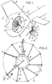
- the tail boom 1 of a helicopter supports at its rear end a empennage 2, the upper part of which is arranged in vertical drift 3, and a horizontal drift with two planes 4 extending on either side of the beam 1.
- the base of the empennage 2 is arranged in hull 5 transversely crossed by a flow vein 6 of air from a faired anti-torque device also comprising a multi-blade rotor 7 with variable pitch, rotatably mounted and substantially coaxial in vein 6, as well as a stator rectifier 8, fixed downstream of the rotor 7 in the vein 6 by relation to the direction of flow of the air flow passing through this last, and having fixed vanes 9.
- the vein 6 has, around its axis X-X substantially transverse to the longitudinal axis of the helicopter, a form of revolution substantially described with reference to the FIG. 3, and comprising a converging entry 10, on board rounded, prolonged, towards the exit of the vein 6, by a cylindrical part 11, itself extended to the outlet by a divergent 12.
- the rotor 7 is mounted in the vein 6 of the side of its entrance and so that its 13 blades turn in the cylindrical part 11 of the vein 6, the axes of pitch change of the blades 13 defining a plane P of rotation of the rotor, in which they move and which is substantially perpendicular to the X-X axis of the streamlined vein 6.
- the rotor 7 is mounted and rotated on a body central 14, of cylindrical-conical external shape and substantially coaxial with the vein 6, this body 14 being integral with the empennage 2 structure via vanes 9 rectifier 8, which hold the body 14 in the center of the vein 6 and on the side of its outlet relative to the rotor 7.
- the body 14 is produced by machining a block of aluminum alloy from a blank optionally forged. In known manner, the body 14 envelops a mechanism for driving the rotor 7 in rotation by a shaft motor 15, itself driven from a drive shaft crossing an arm 16 and connected to an annex outlet from the main gearbox of the helicopter. A part of the arm 16 is arranged substantially radially in the vein 6, in place substantially of one of the blades 9 of the rectifier 8, in the space delimited between the two blades 9 the most separated from each other in Figure 2.
- the body 14 and the rotor 7 comprise a collective control device for the pitch of the blades 13, actuated by a control rod, not shown, because the arm 16 of FIG. 1 serves as a fairing for the shaft of transmission and to this connecting rod.
- vanes 9, fixed in the vein 6 downstream of the blades 13 of the rotor 7, without however coming out of the divergent 12 of vein 6, provide energy recovery from rotation of the air flow downstream of the blades 13, in straightening this flow towards the X-X axis of the vein 6, and by providing additional torque boost, such as explained in French patent FR 2,534,222 of the applicant, the description of which is incorporated herein descriptive memory by reference, in particular as regards the description of Figures 4 and 5 of this patent.
- the straightening of the air flow by the vanes 9 is notably ensured by the appropriate choice of aerodynamic profile asymmetrical of the blades 9, and in particular of its camber and its angular setting in relation to the X-X axis vein 6.
- the rectifier 8 in a vein 6 1 m in diameter at its part cylindrical 11, includes ten blades 9 with aerodynamic profile and the transmission arm 16, which are regularly distributed in circumferential direction around the X-X axis.
- the arm 16 is substantially radial and of section circular, while each blade 9 has a profile aerodynamics of type NACA 65 with for example a thickness 10% relative, constant camber, chosen between about 21 ° and about 27 °, for example 23 °, and a setting fixed angle chosen between approximately 2 ° and approximately 3 °, by example 2.5 °, and oriented to stitch.
- each dawn 9 is not radial, but inclined in the radial direction of an angle ⁇ between approximately 0 ° and approximately 25 °, measured on the span of dawn 9 to 0.8 R where R is the radius of the vein 6 as shown in Figure 2, this inclination being assured of the foot 17 of each blade 9, by which it is fixed to the body 14, towards the end 18 of the blade 9, by which it is fixed to the side and annular wall 6a of the fairing vein 6, in the opposite direction to the direction of rotation of the blades 13 of the rotor 7, indicated by the arrow ⁇ .
- This inclination ⁇ decreases also the noise of rotation of the rotor 7, because it avoids that the interference between the wake of a blade 13 and a dawn 9 does happen simultaneously across the span common to the blade and to the dawn, since the blades 13 are substantially radial with respect to the X-X axis of the vein 6.
- each blade 9 which is relate individually to the cylindrical part of the body 14 and on the frustoconical surface of the divergent 12, are also arranged so that each blade 9 is further inclined soaring from its foot 17 towards its end 18 and from upstream towards downstream in the vein 6, at an angle ⁇ , as shown on the figure 3, chosen between approximately 0 ° and approximately 6 °, for example 4 °.
- This inclination ⁇ makes it possible to spread the leading edge vanes 9 of the plane of rotation P of the blades 13, and therefore trailing edge of these, especially in the peripheral part of the vein 6, which is favorable to a reduction in the interference noise between the blades 13 and the vanes 9.
- the blades 9 can hold the body 14 close of the plane P of rotation of the rotor 7, which promotes a proper centering of the latter in the vein 6.
- the parts end 17 'and 18' of the profile section 9 ' are then machined, for example cut out, removing each 17 'and 18' ends of the material in the edge area leading edge 21 and trailing edge 22 (and more significant from the trailing edge 22 to the side member 23 at the end 18 ′ on the side intended to form the tip of the blade 18), then removing material from the ends of the spar 23 (see Figure 7) so as to form each 17 'or 18' end, extensions of the upper surface 19 and of the lower surface 20.
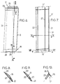
- Figure 9 shows the aerodynamic profile of the main part 24 of dawn 9, thinner than the profile of Figure 8, the section 9 'of hollow extruded section.
- the blade root 17 is thus arranged as a foot end 25 with two fixing lugs 26 in one piece with the current part 24.
- end piece 28 which also includes two fixing lugs 29 external to the profile but in one piece with the latter and generally transverse to the passing longitudinal plane by the rope of dawn 9, as are also the legs attachment 26 of the nozzle 25.
- each leg 26 and one of the legs 29 extends above the upper part 19 and the other below of the lower part 20 of dawn 9, each leg 26 having substantially a rectangular shape with vertices rounded, (as shown in figure 12), which spans most of the chord of dawn 9, while each leg 29 rather has the shape of a substantially trapezoid rounded vertices, extending to the right of the side member 23, and on a smaller portion of rope, as shown in the figure 13.
- Figures 5, 6, 10 and 11 also show that the transverse legs 26 and 29 are curved and inclined by so as to have a substantially corresponding curvature and respectively to that of the external surface of the body 14 and of the internal surface of the wall of the vein 6a, on which they apply to be fixed there, by four rivets 27 for each tab 26 on the body 14, as shown in Figure 12, and by a screw 30 for retain each leg 29 on the wall of the vein 6a, as shown in Figure 13.
- the curvature of the legs 26 is much more marked than that of the legs 29, which can actually be noticeably flat, given their low dimensions relative to the radius of the vein 6.
- the inclinations legs 26 and 29 relative to the current part 24 are such that they give the dawn 9 the angles of inclination ⁇ in the radial direction and ⁇ in arrow (see Figures 2 and 3) when the foot 17 and the end 18 of the blade 9 are fixed respectively to the body 14 and to the wall 6a of the vein 6 by the transverse legs 26 and 29.
- an insert 31 having a support facet 32 can be sealed in the wall of divergent 12, as shown schematically in Figures 3 and 4, so that facet 32 is visible on the internal face of the diverge 12 by being substantially flush with it.
- Each fixing lug 29 is then fixed by a screw 30 to the facet 32 with interposition between them of a peelable shim 33, which can be kept or removed as required, to center the rectifier 8 in the vein 6 and check the clearance under each foot 17 of blade 9, to thus limit the mounting constraints on the body 14.
- the vanes 9, and therefore the rectifier assemblies 8, are interchangeable.
- Figure 14 partially shows in section a blade, as described above, and further comprising two foam plugs 34 and 35, inserted in the ends hollow of the main part 24, respectively on the side of the foot and the tip of the blade, to prevent whistling that could cause air flows in the dawn 9.
- FIG. 15 represents a second example of a blade, limited to its foot fixed to the body 14.
- the running part 24 of the blade is formed of a section of profile 9 'cut substantially the length of the span of dawn, and whose 17 'and 18' end portions are neither clipped nor arched. But the central part between them is machined chemically to reduce its thickness.
- the foot dawn is achieved by engaging and securing the end portion 17 ′ in the sleeve 37 of an end piece foot 36, for example made of sheet metal, and provided with two tabs attachment 38a and 38b secured to the bottom, which is tightened and substantially closed of the sleeve 37.
- the legs 38a and 38b can be in one piece with sleeve 37 and extend it transversely to the main part 24, and / or does not constitute only one fixing lug, possibly extending only on one side of dawn.
- the end 18 ′ of the profile section is fitted and secured inside a sleeve of a tip blade also comprising one or two fixing lugs external to the sleeve and generally transverse to the plane longitudinal passing through the dawn rope, in order to present favorably for fixing against the wall of vein 6a.
- the third example of dawn in Figures 16 and 17 does not essentially differs from that described above in reference to Figure 15 only by making the end caps brought up from the foot and the tip of dawn and mounted on the ends of the section of hollow metal profile.
- the tip 39 of the blade root 17 comprises a relatively massive metallic member 40, which is fitted and retained in the corresponding end of the section of hollow metal profile constituting the part current 24 of dawn.
- This element 40 or core is integral, by its base, fixing lugs 41a and 41b which are folded one above the upper part 19 and the other below the lower part 20 of the part streamline 24, which are curved and inclined by the same way as legs 26, 38a and 38b of the examples previous.
- the legs 41a and 41b can be of a single sheet metal part with the core 40, for example bent into a U in its part introduced into the profiled section of the blade, and are fixed each by four rivets on the external surface of the body 14, as in the example of FIGS. 5 to 13.
- the tip 42 of the blade tip comprises a relatively solid and metallic member or core 43, fitted and retained in the corresponding end of the section of hollow metal profile forming the part current 24 of dawn, this core 43 also carrying, by its base, two fixing lugs 44a and 44b, which are inclined transversely, relative to the span of dawn, and possibly curved, in the same way as the legs fixing the previous examples, to be fixed, by example by two screws 45, against the internal face of the divergent 12 of vein 6, via a monolithic insert such as 31 in FIG. 4.
- lugs 44a and 44b for fixing the end piece 42 of the blade tip can be in one piece with the core 43, made of metal sheet folded into a U in the section of streamlined.
- the tip of the blade root can be one of the three types described above, and the end cap dawn of another of these three types, with one or more fixing lugs for each.
Landscapes
- Engineering & Computer Science (AREA)
- Mechanical Engineering (AREA)
- Aviation & Aerospace Engineering (AREA)
- Structures Of Non-Positive Displacement Pumps (AREA)
Description
- une veine, d'axe sensiblement transversal à l'hélicoptère et traversant une carène dans la partie arrière de l'hélicoptère,
- un rotor, sensiblement coaxial à la veine, et monté en rotation dans la veine sur un corps central, également sensiblement coaxial à la veine, de sorte que sa rotation engendre un écoulement d'air dans la veine, et
- un stator redresseur, fixé dans la veine en aval du rotor par rapport au sens d'écoulement de l'air, et comportant des aubes présentant, chacune, une partie courante à profil aérodynamique redressant le flux d'air en aval du rotor vers l'axe de la veine, ainsi qu'un pied d'aube et un bout d'aube aux extrémités respectives de la partie courante, et par lesquels l'aube est liée respectivement au corps central et à la paroi annulaire de la veine, de façon à supporter le corps dans cette dernière, et le redresseur se caractérise en ce que chaque aube comprend une partie centrale métallique creuse, formant au moins sa partie courante, et en ce que l'un au moins de ses pied et bout d'aube est agencé en embout muni d'au moins une patte transversale de fixation au corps central ou à la paroi de la veine.
- filer un profilé métallique creux de section correspondant au profil aérodynamique de l'aube,
- découper un tronçon de profilé de longueur au moins égale à l'envergure de la partie profilée de l'aube, et
- agencer au moins une extrémité du tronçon de profilé en embout muni d'au moins une patte de fixation, pour fixer l'embout respectivement sur le corps ou sur la paroi de la veine.
- la figure 1 est une vue en perspective de 3/4 arrière d'un dispositif anti-couple caréné, avec rotor et stator redresseur disposés dans une veine traversant la partie arrière d'un hélicoptère, le rotor étant représenté sorti de la veine avec arrachement partiel, pour plus de clarté,
- la figure 2 est une vue schématique partielle, en élévation latérale depuis la sortie de la veine, du redresseur de la figure 1,
- la figure 3 est une coupe selon III-III de la figure 2, et avec une coupe axiale de la liaison d'un bout d'aube à la paroi de la veine,
- la figure 4 représente, à plus grande échelle, la coupe axiale détaillée de la liaison du bout d'aube à la veine,
- la figure 5 est une vue à plus grande échelle et de l'arrière d'une aube du redresseur de la figure 2,
- la figure 6 est une vue en élévation latérale selon la flèche VI de l'aube de la figure 5,
- la figure 7 est une vue en coupe selon VII-VII de l'aube de la figure 5,
- les figures 8 et 9 sont des coupes transversales de l'aube selon VIII-VIII et IX-IX de la figure 7,
- les figures 10 et 11 sont des coupes partielles selon X-X et XI-XI de la figure 6, respectivement au niveau du pied et du bout de l'aube,
- les figures 12 et 13 sont des vues selon les flèches XII et XIII respectivement sur la figure 5 et sur la figure 2 et montrant les pattes de fixation du pied et du bout de l'aube,
- la figure 14 est une coupe longitudinale partielle d'une variante de l'aube des figures précédentes, la coupe étant limitée aux parties du pied et du bout de l'aube,
- la figure 15 est une vue schématique et partielle représentant de l'arrière la liaison du pied d'un second exemple d'aube au corps, et
- les figures 16 et 17 sont des vues correspondant sensiblement et respectivement aux figures 5 et 6 pour un troisième exemple d'aube.
Claims (15)
- Redresseur à aubes, pour dispositif anti-couple d'hélicoptère comprenant :une veine (6), d'axe (X-X) sensiblement transversal à l'hélicoptère et traversant une carène (5) dans la partie arrière de l'hélicoptère,un rotor (7), sensiblement coaxial à la veine (6), et monté en rotation dans la veine (6) sur un corps central (14), également sensiblement coaxial à la veine (6), de sorte que sa rotation engendre un écoulement d'air dans la veine (6), etun stator redresseur (8), fixé dans la veine (6) en aval du rotor (7) par rapport au sens d'écoulement de l'air, et comportant des aubes (9) présentant, chacune, une partie courante (24) à profil aérodynamique redressant le flux d'air en aval du rotor (7) vers l'axe (X-X) de la veine (6), ainsi qu'un pied d'aube (17) et un bout d'aube (18) aux extrémités respectives de la partie courante (24), et par lesquels l'aube (9) est liée respectivement au corps central (14) et à la paroi annulaire (6a) de la veine (6), de façon à supporter le corps (14) dans cette dernière, le redressseur (8) étant caractérisé en ce que chaque aube (9) comprend une partie centrale métallique creuse, formant au moins sa partie courante (24), et en ce que l'un au moins de ses pied (17) et bout (18) d'aube (9) est agencé en embout (25, 28, 36, 39, 42) muni d'au moins une patte (26, 29, 38a, 38b, 41a, 41b, 44a, 44b) transversale de fixation au corps central (14) ou à la paroi de la veine (6).
- Redresseur à aubes selon la revendication 1, caractérisé en ce que ladite partie centrale creuse est un tronçon de profilé creux (9'), de section correspondant au profil aérodynamique s'étendant du pied d'aube (17) au bout d'aube (18).
- Redresseur à aubes selon la revendication 2, caractérisé en ce qu'au moins un embout de pied (39) ou de bout (42) d'aube comprend un organe (40, 43), emmanché dans une partie d'extrémité correspondante du tronçon de profilé (9'), et portant la ou les pattes de fixation (41a, 41b, 44a, 44b) correspondantes, qui s'étendent transversalement à l'envergure de l'aube à l'extérieur dudit tronçon de profilé (9').
- Redresseur à aubes selon la revendication 2, caractérisé en ce qu'au moins un embout de pied (36) ou de bout d'aube est agencé en manchon (37), dans lequel est engagée une partie d'extrémité du tronçon de profilé (9'), le manchon (37) portant la ou les pattes de fixation correspondantes (38a, 38b).
- Redresseur à aubes selon la revendication 2, caractérisé en ce qu'au moins un embout de pied (25) ou de bout (28) d'aube (9) est d'une seule pièce avec le tronçon de profilé (9') et chacune de ses pattes de fixation (26, 29) est cambrée par rapport à l'extrados (19) et/ou l'intrados (20) de l'aube (9) que ladite patte prolonge.
- Redresseur à aubes selon l'une quelconque des revendications 1 à 5, caractérisé en ce que chaque patte de fixation (26, 29, 38a, 38b, 41a, 41b, 44a, 44b) d'un embout de pied (25, 36, 39) ou de bout (28, 42) d'aube s'étend audessus de la partie d'extrados (19) et/ou au-dessous de la partie d'intrados (20) de l'aube (9) correspondante, et/ou est cintrée avec une courbure correspondant sensiblement à celle de la surface du corps central (14) ou de la veine (6) sur laquelle ladite patte est destinée à être fixée.
- Redresseur à aubes selon l'une quelconque des revendications 1 à 6, caractérisé en ce que l'épaisseur d'une aube, dans la portion centrale (24) de sa partie creuse, est inférieure à son épaisseur dans les portions d'extrémité (17', 18') de ladite partie creuse.
- Redresseur à aubes selon l'une quelconque des revendications 1 à 7, caractérisé en ce qu'au moins une aube (9) comprend un longeron (23) raccordant la partie d'extrados (19) à la partie d'intrados (20) de l'aube (9), et au droit duquel s'étend au moins une patte (26, 29, 38a, 38b, 41a, 41b, 44a, 44b) de fixation de l'un au moins des embouts de pied (25, 36, 39) et de bout (28, 42) d'aube.
- Redresseur à aubes selon l'une quelconque des revendications 1 à 8, caractérisé en ce que la ou les pattes de fixation (26) du pied d'au moins une aube (17) se fixent par rivetage (27) sur l'extérieur du corps central (14) et la ou les pattes de fixation (29) du bout d'aube (18) se fixent par vissage (30) sur au moins un insert (31) monté dans la paroi de la veine (6), avec, en cas de besoin, interposition d'une cale amovible (33) sous la ou les pattes de fixation (29) du bout d'aube (18), pour effectuer le centrage du redresseur (8) dans la veine (6).
- Redresseur à aubes selon l'une quelconque des revendications 1 à 9, caractérisé en ce que les pattes de fixation (26, 29, 38a, 38b, 41a, 41b, 44a, 44b) du pied (17) et/ou du bout (18) d'au moins une aube (9) sont inclinées et/ou cintrées par rapport au plan longitudinal s'étendant selon l'envergure et passant par la corde de l'aube (9) de sorte que l'aube (9), fixée entre le corps central (14) et la paroi de la veine (6), est inclinée sur la direction radiale par rapport à l'axe (X-X) de la veine (6).
- Redresseur à aubes selon l'une quelconque des revendications 1 à 10, caractérisé en ce que les pattes de fixation (26, 29, 38a, 38b, 41a, 41b, 44a, 44b) du pied (17) et/ou du bout (18) d'au moins une aube (9) sont inclinées et/ou cintrées par rapport au plan longitudinal passant par la corde de l'aube (9) de sorte que l'aube (9), fixée entre le corps central (14) et la paroi de la veine (6), est inclinée en flèche de son pied (17) vers son bout (18) et de l'amont vers l'aval dans la veine (6).
- Procédé de fabrication d'une aube (9) de redresseur (8) à profil aérodynamique pour, d'une part, supporter un corps central (14) sensiblement coaxialement dans une veine (6) traversant une partie arrière d'hélicoptère et d'axe (X-X) sensiblement transversal à l'hélicoptère, et en aval d'un rotor (7) sensiblement coaxial, monté en rotation sur le corps (14) et tournant dans la veine (6), et, d'autre part, redresser, en aval du rotor (7), le flux d'air engendré par la rotation du rotor (7) dans la veine (6), caractérisé en ce qu'il comprend les étapes consistant à :filer un profilé métallique creux de section correspondant au profil aérodynamique de l'aube (9),découper un tronçon de profilé (9') de longueur au moins égale à l'envergure de la partie profilée de l'aube (9), etagencer au moins une extrémité du tronçon de profilé (9') en embout (25, 28, 36, 39, 42) muni d'au moins une patte de fixation (26, 29, 38a, 38b, 41a, 41b, 44a, 44b), pour fixer l'embout respectivement sur le corps (14) ou sur la paroi de la veine (6).
- Procédé selon la revendication 12, caractérisé en ce qu'il comprend de plus les étapes consistant à détourer au moins une partie d'extrémité (17', 18') du tronçon de profilé (9') au niveau du bord d'attaque (21) et du bord de fuite (22) de l'aube (9), de façon à former au moins un prolongement de l'extrados (19) et au moins un prolongement de l'intrados (20), puis à cambrer lesdits prolongements transversalement à l'aube (9) de façon à former lesdites pattes de fixation (26, 29).
- Procédé selon l'une des revendications 12 et 13, caractérisé en ce qu'il comprend de plus l'étape consistant à usiner chimiquement au moins l'extérieur de la partie centrale (24) du tronçon de profilé creux (9'), afin d'en réduire l'épaisseur.
- Procédé selon l'une des revendications 12 à 14, caractérisé en ce qu'il consiste à cintrer et/ou incliner au moins une patte de fixation (26, 29, 38a, 38b, 41a, 41b, 44a, 44b) d'un embout d'aube (25, 28, 36, 39, 42), d'une manière à permettre la conformation de la patte à la forme du corps (14) ou de la paroi de la veine (6) et/ou l'inclinaison de l'aube (9) en flèche du corps (14) vers la veine (6) et de l'amont vers l'aval de la veine (6) et/ou par rapport à la direction radiale dans la veine (6).
Applications Claiming Priority (2)
| Application Number | Priority Date | Filing Date | Title |
|---|---|---|---|
| FR9405480A FR2719552B1 (fr) | 1994-05-04 | 1994-05-04 | Aube de redresseur pour dispositif anti-couple à rotor et stator redresseur carénés d'hélicoptère. |
| FR9405480 | 1994-05-04 |
Publications (2)
| Publication Number | Publication Date |
|---|---|
| EP0680874A1 EP0680874A1 (fr) | 1995-11-08 |
| EP0680874B1 true EP0680874B1 (fr) | 1998-07-29 |
Family
ID=9462874
Family Applications (1)
| Application Number | Title | Priority Date | Filing Date |
|---|---|---|---|
| EP95400999A Expired - Lifetime EP0680874B1 (fr) | 1994-05-04 | 1995-05-02 | Redresseur à aubes pour dispositif anti-couple à rotor et stator redresseur carénés d'hélicoptère |
Country Status (4)
| Country | Link |
|---|---|
| US (2) | US5454691A (fr) |
| EP (1) | EP0680874B1 (fr) |
| DE (1) | DE69503694T2 (fr) |
| FR (1) | FR2719552B1 (fr) |
Families Citing this family (14)
| Publication number | Priority date | Publication date | Assignee | Title |
|---|---|---|---|---|
| FR2721000B1 (fr) * | 1994-06-10 | 1996-08-23 | Eurocopter France | Aube de redresseur en composite, redresseur la comportant, pour dispositif anti-couple à rotor et stator redresseur carénés, et leur procédé de fabrication. |
| KR100734649B1 (ko) * | 1997-11-17 | 2007-07-02 | 시게이트 테크놀로지 엘엘씨 | 프레임 수신을 위한 방법과 전용 프레임 버퍼 |
| ATE449237T1 (de) | 2004-07-16 | 2009-12-15 | Bell Helicopter Textron Inc | Gegendrehmomentvorrichtung für hubschrauber |
| FR2968272B1 (fr) * | 2010-12-06 | 2013-07-12 | Eurocopter France | Element de structure ameliore d'un giravion pour diminuer la trainee aerodynamique. |
| US8690531B2 (en) | 2010-12-30 | 2014-04-08 | General Electroc Co. | Vane with spar mounted composite airfoil |
| US8727721B2 (en) * | 2010-12-30 | 2014-05-20 | General Electric Company | Vane with spar mounted composite airfoil |
| FR2987346B1 (fr) | 2012-02-27 | 2014-08-29 | Eurocopter France | Pale de rotor, rotor, aeronef, et procede |
| EP2671798B1 (fr) * | 2012-06-08 | 2015-08-05 | AIRBUS HELICOPTERS DEUTSCHLAND GmbH | Hélicoptère avec un conduit transversal |
| US10184488B2 (en) * | 2013-02-25 | 2019-01-22 | Greenheck Fan Corporation | Fan housing having flush mounted stator blades |
| CA2902316C (fr) | 2013-02-25 | 2018-10-09 | Greenheck Fan Corporation | Ensemble ventilateur helicocentrifuge |
| US10125783B2 (en) | 2013-02-25 | 2018-11-13 | Greenheck Fan Corporation | Fan assembly and fan wheel assemblies |
| EP2878433B1 (fr) * | 2013-11-29 | 2016-04-20 | AIRBUS HELICOPTERS DEUTSCHLAND GmbH | Ensemble rotatif caréné de composite segmenté pour aéronef et procédé pour sa fabrication |
| US10889366B2 (en) | 2018-09-21 | 2021-01-12 | Textron Innovations Inc. | Ducted thrusters |
| EP4361037B1 (fr) | 2022-10-28 | 2025-07-30 | AIRBUS HELICOPTERS DEUTSCHLAND GmbH | Giravion avec une poutre de queue ayant un rotor anti-couple caréné |
Family Cites Families (9)
| Publication number | Priority date | Publication date | Assignee | Title |
|---|---|---|---|---|
| FR1531536A (fr) * | 1967-05-22 | 1968-07-05 | Sud Aviation | Hélice ou rotor à pas variable |
| FR1593008A (fr) * | 1968-07-11 | 1970-05-25 | ||
| FR2534222A1 (fr) * | 1982-10-06 | 1984-04-13 | Aerospatiale | Agencement de rotor de queue a poussee accrue pour aeronef a voilure tournante et dispositif pour accroitre la poussee d'un tel agencement |
| FR2542695B1 (fr) * | 1983-03-18 | 1985-07-26 | Aerospatiale | Helice multipale a pas variable a pale s en materiaux composites demontables individuellement, procede de fabrication de telles pales et pales ainsi realisees |
| GB2145774A (en) * | 1983-08-31 | 1985-04-03 | Dowty Rotol Ltd | Bladed rotors and ducts associated therewith |
| US4594761A (en) * | 1984-02-13 | 1986-06-17 | General Electric Company | Method of fabricating hollow composite airfoils |
| US5131604A (en) * | 1991-04-11 | 1992-07-21 | United Technologies Corporation | Helicopter antitorque device |
| FR2683504A1 (fr) * | 1991-11-07 | 1993-05-14 | Aerospatiale | Systeme anticouple a rotor arriere pour helicoptere. |
| US5272869A (en) * | 1992-12-10 | 1993-12-28 | General Electric Company | Turbine frame |
-
1994
- 1994-05-04 FR FR9405480A patent/FR2719552B1/fr not_active Expired - Lifetime
- 1994-09-01 US US08/298,310 patent/US5454691A/en not_active Expired - Lifetime
-
1995
- 1995-04-13 US US08/422,314 patent/US5619797A/en not_active Expired - Lifetime
- 1995-05-02 DE DE69503694T patent/DE69503694T2/de not_active Expired - Lifetime
- 1995-05-02 EP EP95400999A patent/EP0680874B1/fr not_active Expired - Lifetime
Also Published As
| Publication number | Publication date |
|---|---|
| DE69503694D1 (de) | 1998-09-03 |
| FR2719552A1 (fr) | 1995-11-10 |
| US5619797A (en) | 1997-04-15 |
| FR2719552B1 (fr) | 1996-07-26 |
| EP0680874A1 (fr) | 1995-11-08 |
| US5454691A (en) | 1995-10-03 |
| DE69503694T2 (de) | 1999-04-15 |
Similar Documents
| Publication | Publication Date | Title |
|---|---|---|
| EP0107543B1 (fr) | Agencement de rotor de queue de poussée accrue pour aéronef à voilure tournante | |
| CA2849677C (fr) | Rotor carene d'aeronef, et giravion | |
| EP0680874A1 (fr) | Aube de redresseur pour dispositif anti-couple à rotor et stator redresseur carénés d'hélicoptère | |
| EP4185521B1 (fr) | Turbomachine d'aeronef comportant des aubes d'helice a calage variable | |
| EP4107062A1 (fr) | Pale composite pour rotor de turbomachine | |
| EP0298826A1 (fr) | Pale à extrémité courbe pour voilure tournante d'aéronef | |
| EP0036825B1 (fr) | Pale à hautes performances pour rotor d'hélicoptère | |
| EP2631169B1 (fr) | Rotor, aéronef et procédé | |
| EP1452741A1 (fr) | Aube en flèche de turboréacteur | |
| EP0067097B1 (fr) | Extrémité de pale pour voilure tournante d'aéronef | |
| FR3118094A1 (fr) | Aube de stator avec portion mobile, module de turbomachine equipe d’une telle aube de stator et turbomachine correspondante | |
| EP2818408B1 (fr) | Pale à rigidité en torsion réduite et rotor muni d'une telle pale | |
| FR3021706A1 (fr) | Turbopropulseur d'aeronef comportant deux helices coaxiales. | |
| FR3046442A1 (fr) | Arbre d'entrainement d'aeropompe reglee | |
| EP2432684B1 (fr) | Procédé pour l'amélioration de l'efficacité aérodynamique de l'empennage vertical d'un aéronef | |
| EP4522869A1 (fr) | Turbomachine d'aeronef comportant des aubes d'helice a calage variable | |
| CA3059098C (fr) | Systeme carene et aeronef | |
| FR3120650A1 (fr) | Turbomachine d’aeronef comportant des aubes d’helice a calage variable | |
| EP3984883A1 (fr) | Methode d'amelioration du comportement aerodynamique de pales d'un giravion en vol stationnaire par un deplacement du bord d'attaque des profils aerodynamiques de ces pales | |
| WO2017144807A1 (fr) | Moyeu d'hélice à pales à calage variable avec variation radiale et axiale de dimensionnement | |
| FR3048719A1 (fr) | Redresseur de flux pour turbomachine avec plateformes integrees et rapportees | |
| EP4118342A1 (fr) | Bras de maintien pour armature de support | |
| WO2020207955A1 (fr) | Voilure tournante dans le domaine des aeronefs | |
| WO2025172659A1 (fr) | Propulseur aéronautique non-caréné | |
| WO2025172660A1 (fr) | Propulseur aéronautique non-caréné |
Legal Events
| Date | Code | Title | Description |
|---|---|---|---|
| PUAI | Public reference made under article 153(3) epc to a published international application that has entered the european phase |
Free format text: ORIGINAL CODE: 0009012 |
|
| AK | Designated contracting states |
Kind code of ref document: A1 Designated state(s): DE GB IT |
|
| 17P | Request for examination filed |
Effective date: 19960315 |
|
| 17Q | First examination report despatched |
Effective date: 19970617 |
|
| GRAG | Despatch of communication of intention to grant |
Free format text: ORIGINAL CODE: EPIDOS AGRA |
|
| RAP1 | Party data changed (applicant data changed or rights of an application transferred) |
Owner name: EUROCOPTER |
|
| GRAG | Despatch of communication of intention to grant |
Free format text: ORIGINAL CODE: EPIDOS AGRA |
|
| GRAH | Despatch of communication of intention to grant a patent |
Free format text: ORIGINAL CODE: EPIDOS IGRA |
|
| GRAH | Despatch of communication of intention to grant a patent |
Free format text: ORIGINAL CODE: EPIDOS IGRA |
|
| GRAA | (expected) grant |
Free format text: ORIGINAL CODE: 0009210 |
|
| AK | Designated contracting states |
Kind code of ref document: B1 Designated state(s): DE GB IT |
|
| ITF | It: translation for a ep patent filed | ||
| GBT | Gb: translation of ep patent filed (gb section 77(6)(a)/1977) |
Effective date: 19980729 |
|
| REF | Corresponds to: |
Ref document number: 69503694 Country of ref document: DE Date of ref document: 19980903 |
|
| PLBE | No opposition filed within time limit |
Free format text: ORIGINAL CODE: 0009261 |
|
| STAA | Information on the status of an ep patent application or granted ep patent |
Free format text: STATUS: NO OPPOSITION FILED WITHIN TIME LIMIT |
|
| 26N | No opposition filed | ||
| REG | Reference to a national code |
Ref country code: GB Ref legal event code: IF02 |
|
| PGFP | Annual fee paid to national office [announced via postgrant information from national office to epo] |
Ref country code: GB Payment date: 20110503 Year of fee payment: 17 |
|
| PGFP | Annual fee paid to national office [announced via postgrant information from national office to epo] |
Ref country code: DE Payment date: 20110505 Year of fee payment: 17 |
|
| GBPC | Gb: european patent ceased through non-payment of renewal fee |
Effective date: 20120502 |
|
| REG | Reference to a national code |
Ref country code: DE Ref legal event code: R119 Ref document number: 69503694 Country of ref document: DE Effective date: 20121201 |
|
| PG25 | Lapsed in a contracting state [announced via postgrant information from national office to epo] |
Ref country code: GB Free format text: LAPSE BECAUSE OF NON-PAYMENT OF DUE FEES Effective date: 20120502 |
|
| PG25 | Lapsed in a contracting state [announced via postgrant information from national office to epo] |
Ref country code: DE Free format text: LAPSE BECAUSE OF NON-PAYMENT OF DUE FEES Effective date: 20121201 |
|
| PGFP | Annual fee paid to national office [announced via postgrant information from national office to epo] |
Ref country code: IT Payment date: 20140428 Year of fee payment: 20 |