EP0679848B1 - Sliding refrigerator shelf assembly - Google Patents
Sliding refrigerator shelf assembly Download PDFInfo
- Publication number
- EP0679848B1 EP0679848B1 EP95302593A EP95302593A EP0679848B1 EP 0679848 B1 EP0679848 B1 EP 0679848B1 EP 95302593 A EP95302593 A EP 95302593A EP 95302593 A EP95302593 A EP 95302593A EP 0679848 B1 EP0679848 B1 EP 0679848B1
- Authority
- EP
- European Patent Office
- Prior art keywords
- shelf
- slide
- support
- panel
- flange
- Prior art date
- Legal status (The legal status is an assumption and is not a legal conclusion. Google has not performed a legal analysis and makes no representation as to the accuracy of the status listed.)
- Expired - Lifetime
Links
- 239000011521 glass Substances 0.000 claims description 27
- 239000000463 material Substances 0.000 claims description 26
- 238000000034 method Methods 0.000 claims description 19
- 238000004519 manufacturing process Methods 0.000 claims description 17
- 238000000465 moulding Methods 0.000 claims description 17
- 238000002347 injection Methods 0.000 claims description 7
- 239000007924 injection Substances 0.000 claims description 7
- 229920001169 thermoplastic Polymers 0.000 claims description 7
- 239000004416 thermosoftening plastic Substances 0.000 claims description 7
- 229920001577 copolymer Polymers 0.000 claims 1
- HQQADJVZYDDRJT-UHFFFAOYSA-N ethene;prop-1-ene Chemical group C=C.CC=C HQQADJVZYDDRJT-UHFFFAOYSA-N 0.000 claims 1
- 238000010438 heat treatment Methods 0.000 claims 1
- 230000000452 restraining effect Effects 0.000 claims 1
- 238000000576 coating method Methods 0.000 description 8
- 239000012530 fluid Substances 0.000 description 7
- 239000000843 powder Substances 0.000 description 7
- 230000000712 assembly Effects 0.000 description 6
- 238000000429 assembly Methods 0.000 description 6
- 239000011248 coating agent Substances 0.000 description 6
- 239000004033 plastic Substances 0.000 description 6
- 229920003023 plastic Polymers 0.000 description 6
- 239000007788 liquid Substances 0.000 description 5
- 239000004593 Epoxy Substances 0.000 description 4
- VGGSQFUCUMXWEO-UHFFFAOYSA-N Ethene Chemical compound C=C VGGSQFUCUMXWEO-UHFFFAOYSA-N 0.000 description 4
- 239000005977 Ethylene Substances 0.000 description 4
- 229910000831 Steel Inorganic materials 0.000 description 4
- 235000013305 food Nutrition 0.000 description 4
- 229920000728 polyester Polymers 0.000 description 4
- -1 polypropylene Polymers 0.000 description 4
- 239000010959 steel Substances 0.000 description 4
- 239000005341 toughened glass Substances 0.000 description 4
- 239000004743 Polypropylene Substances 0.000 description 3
- 229920001155 polypropylene Polymers 0.000 description 3
- 238000003860 storage Methods 0.000 description 3
- GWEVSGVZZGPLCZ-UHFFFAOYSA-N Titan oxide Chemical compound O=[Ti]=O GWEVSGVZZGPLCZ-UHFFFAOYSA-N 0.000 description 2
- 238000005260 corrosion Methods 0.000 description 2
- 230000007797 corrosion Effects 0.000 description 2
- 238000003780 insertion Methods 0.000 description 2
- 230000037431 insertion Effects 0.000 description 2
- QQONPFPTGQHPMA-UHFFFAOYSA-N propylene Natural products CC=C QQONPFPTGQHPMA-UHFFFAOYSA-N 0.000 description 2
- 125000004805 propylene group Chemical group [H]C([H])([H])C([H])([*:1])C([H])([H])[*:2] 0.000 description 2
- 238000005057 refrigeration Methods 0.000 description 2
- 239000012260 resinous material Substances 0.000 description 2
- 238000005096 rolling process Methods 0.000 description 2
- XLYOFNOQVPJJNP-UHFFFAOYSA-N water Substances O XLYOFNOQVPJJNP-UHFFFAOYSA-N 0.000 description 2
- 239000004698 Polyethylene Substances 0.000 description 1
- 208000003028 Stuttering Diseases 0.000 description 1
- DHKHKXVYLBGOIT-UHFFFAOYSA-N acetaldehyde Diethyl Acetal Natural products CCOC(C)OCC DHKHKXVYLBGOIT-UHFFFAOYSA-N 0.000 description 1
- 125000002777 acetyl group Chemical class [H]C([H])([H])C(*)=O 0.000 description 1
- 238000004140 cleaning Methods 0.000 description 1
- 238000010276 construction Methods 0.000 description 1
- 238000011109 contamination Methods 0.000 description 1
- 230000001419 dependent effect Effects 0.000 description 1
- 238000009826 distribution Methods 0.000 description 1
- 239000003302 ferromagnetic material Substances 0.000 description 1
- 238000009434 installation Methods 0.000 description 1
- 235000013372 meat Nutrition 0.000 description 1
- 239000000049 pigment Substances 0.000 description 1
- 229920000573 polyethylene Polymers 0.000 description 1
- 239000004800 polyvinyl chloride Substances 0.000 description 1
- 229920000915 polyvinyl chloride Polymers 0.000 description 1
- 238000007789 sealing Methods 0.000 description 1
- 238000006467 substitution reaction Methods 0.000 description 1
- 239000000725 suspension Substances 0.000 description 1
- 239000004408 titanium dioxide Substances 0.000 description 1
- 235000013311 vegetables Nutrition 0.000 description 1
- KHADWTWCQJVOQO-UHFFFAOYSA-N zinc;oxido-(oxido(dioxo)chromio)oxy-dioxochromium Chemical compound [Zn+2].[O-][Cr](=O)(=O)O[Cr]([O-])(=O)=O KHADWTWCQJVOQO-UHFFFAOYSA-N 0.000 description 1
Images


Classifications
-
- F—MECHANICAL ENGINEERING; LIGHTING; HEATING; WEAPONS; BLASTING
- F25—REFRIGERATION OR COOLING; COMBINED HEATING AND REFRIGERATION SYSTEMS; HEAT PUMP SYSTEMS; MANUFACTURE OR STORAGE OF ICE; LIQUEFACTION SOLIDIFICATION OF GASES
- F25D—REFRIGERATORS; COLD ROOMS; ICE-BOXES; COOLING OR FREEZING APPARATUS NOT OTHERWISE PROVIDED FOR
- F25D25/00—Charging, supporting, and discharging the articles to be cooled
- F25D25/02—Charging, supporting, and discharging the articles to be cooled by shelves
- F25D25/024—Slidable shelves
-
- B—PERFORMING OPERATIONS; TRANSPORTING
- B29—WORKING OF PLASTICS; WORKING OF SUBSTANCES IN A PLASTIC STATE IN GENERAL
- B29C—SHAPING OR JOINING OF PLASTICS; SHAPING OF MATERIAL IN A PLASTIC STATE, NOT OTHERWISE PROVIDED FOR; AFTER-TREATMENT OF THE SHAPED PRODUCTS, e.g. REPAIRING
- B29C33/00—Moulds or cores; Details thereof or accessories therefor
- B29C33/12—Moulds or cores; Details thereof or accessories therefor with incorporated means for positioning inserts, e.g. labels
- B29C33/123—Moulds or cores; Details thereof or accessories therefor with incorporated means for positioning inserts, e.g. labels for centering the inserts
-
- B—PERFORMING OPERATIONS; TRANSPORTING
- B29—WORKING OF PLASTICS; WORKING OF SUBSTANCES IN A PLASTIC STATE IN GENERAL
- B29C—SHAPING OR JOINING OF PLASTICS; SHAPING OF MATERIAL IN A PLASTIC STATE, NOT OTHERWISE PROVIDED FOR; AFTER-TREATMENT OF THE SHAPED PRODUCTS, e.g. REPAIRING
- B29C33/00—Moulds or cores; Details thereof or accessories therefor
- B29C33/44—Moulds or cores; Details thereof or accessories therefor with means for, or specially constructed to facilitate, the removal of articles, e.g. of undercut articles
- B29C33/442—Moulds or cores; Details thereof or accessories therefor with means for, or specially constructed to facilitate, the removal of articles, e.g. of undercut articles with mechanical ejector or drive means therefor
-
- B—PERFORMING OPERATIONS; TRANSPORTING
- B29—WORKING OF PLASTICS; WORKING OF SUBSTANCES IN A PLASTIC STATE IN GENERAL
- B29C—SHAPING OR JOINING OF PLASTICS; SHAPING OF MATERIAL IN A PLASTIC STATE, NOT OTHERWISE PROVIDED FOR; AFTER-TREATMENT OF THE SHAPED PRODUCTS, e.g. REPAIRING
- B29C45/00—Injection moulding, i.e. forcing the required volume of moulding material through a nozzle into a closed mould; Apparatus therefor
- B29C45/14—Injection moulding, i.e. forcing the required volume of moulding material through a nozzle into a closed mould; Apparatus therefor incorporating preformed parts or layers, e.g. injection moulding around inserts or for coating articles
- B29C45/14336—Coating a portion of the article, e.g. the edge of the article
- B29C45/14434—Coating brittle material, e.g. glass
-
- B—PERFORMING OPERATIONS; TRANSPORTING
- B29—WORKING OF PLASTICS; WORKING OF SUBSTANCES IN A PLASTIC STATE IN GENERAL
- B29C—SHAPING OR JOINING OF PLASTICS; SHAPING OF MATERIAL IN A PLASTIC STATE, NOT OTHERWISE PROVIDED FOR; AFTER-TREATMENT OF THE SHAPED PRODUCTS, e.g. REPAIRING
- B29C45/00—Injection moulding, i.e. forcing the required volume of moulding material through a nozzle into a closed mould; Apparatus therefor
- B29C45/17—Component parts, details or accessories; Auxiliary operations
- B29C45/40—Removing or ejecting moulded articles
- B29C45/44—Removing or ejecting moulded articles for undercut articles
- B29C45/4407—Removing or ejecting moulded articles for undercut articles by flexible movement of undercut portions of the articles
-
- F—MECHANICAL ENGINEERING; LIGHTING; HEATING; WEAPONS; BLASTING
- F25—REFRIGERATION OR COOLING; COMBINED HEATING AND REFRIGERATION SYSTEMS; HEAT PUMP SYSTEMS; MANUFACTURE OR STORAGE OF ICE; LIQUEFACTION SOLIDIFICATION OF GASES
- F25D—REFRIGERATORS; COLD ROOMS; ICE-BOXES; COOLING OR FREEZING APPARATUS NOT OTHERWISE PROVIDED FOR
- F25D2325/00—Charging, supporting or discharging the articles to be cooled, not provided for in other groups of this subclass
- F25D2325/022—Shelves made of glass or ceramic
Definitions
- This invention relates to shelving especially adapted for use in refrigerator compartments, especially refrigerators for food products, and more particularly, to a sliding shelf assembly for refrigerators having improved weight supporting capabilities, improved sliding movement, and an improved method for manufacturing.
- sliding refrigerator shelving Many varieties of sliding refrigerator shelving have been used in the past.
- such sliding shelves include a shelf panel mounted for horizontal sliding extension toward the user through the door opening of the refrigerator to provide better access to items stored on the shelf or for ease in cleaning.
- One prior shelf includes a plurality of preformed frame members assembled around a shelf panel and slidably secured on appropriate support brackets.
- tracks on opposite side surfaces guide sliding movement of the shelf panel.
- EP-A-0507455 discloses a moulded refrigerator shelf which has a planar shelf member with a rim.
- the shelf is slidably mounted and cantilevered on two side support brackets to allow extension of the shelf for easy access to the rear of the shelf. Because the shelf is cantilevered air is allowed to flow around the shelf sides.
- the present invention provides a shelf assembly for refrigerated compartments, and especially refrigerators for food products, in which a shelf member is slidably mounted for extension and retraction on a shelf support, the shelf member including side members which are molded in one piece on an article support surface from a moldable material while incorporating either a molded guide member or an embedded insert which guides sliding movement and restricts vertical movement of the shelf with respect to the support.
- a stop member for limiting extension or retraction is included.
- the invention also encompasses a manufacturing method including the provision of a rigid core having a portion embedded within the molded slide member, which core is withdrawn after molding to provide a slide channel avoiding the necessity of assembling the slide member from multiple parts and also allowing use of the same mold cavity used to form fixed refrigerator shelf versions.
- the invention provides a shelf assembly for a refrigerated compartment as defined in claim 1.
- the shelf support includes a pair of spaced, parallel, L-shaped support brackets each having a body and a laterally extending flange extending at a right angle to the body, the flange having a generally horizontal top surface forming the shelf support surface.
- a further development of the sliding shelf assembly according to the invention comprises:
- the assembly may include a second molded guide member defined by the slide channel on the side portion, the guide members on each side portion being spaced laterally from and extending parallel to one another and depending downwardly adjacent the slide surface.
- the slide channel may be spaced from and extends generally parallel to the shelf member.
- the slide channel is aligned with and below the perimeter edge of the shelf panel.
- the shelf panel is glass and the moldable material is a resinous thermoplastic copolymer.
- the slide channel is adapted to receive a slide support flange of a support bracket, the slide channel being oversized and larger than the support flange to allow sliding movement therebetween.
- a shelf assembly for a refrigerated compartment comprising:
- the rigid member may be a stud embedded in the slide surface of the side member.
- At least one of the shelf support surfaces may include a slot forming the elongated opening; the stud projecting into the slot; the slot having at least one closed end defining the limit surface.
- the stud includes spaced, laterally extending flanges, one stud flange being embedded in the molded side member, the other stud flange extending under the shelf support surface.
- the invention is a shelf assembly for a refrigerated compartment including a shelf support and a shelf member slidably mounted for extension and retraction on the shelf support.
- the shelf support includes a pair of spaced, generally horizontal, generally parallel shelf support surfaces and a guide surface extending at an angle to each shelf support surface.
- At least one mounting member is adapted to mount the shelf support in a refrigerated compartment.
- the shelf member includes a pair of spaced side members molded in one piece on an article support surface from a moldable material, the side members extending along opposite sides of the article support surface. Each side member includes a slide surface engaging one of the shelf support surfaces.
- At least one of the side members has a depending guide member adjacent the guide surface to guide sliding movement of the shelf member, the guide member also including a stop.
- the shelf support also includes an elongated opening for receiving and allowing movement of the shelf when the shelf member is slidably extended or retracted and at least one limit surface for engaging the stop member to limit at least one of the extension and retraction of the shelf member.
- the guide member and stop are molded integrally and in one piece with the side member while a second guide member is also molded on each side member to confine the shelf support surface for proper sliding movement.
- the guide members and slide surface are defined by a slide channel which, in the preferred form, is formed by the preferred method set forth herein.
- the guide member and stop may be formed by a rigid insert embedded within the molded side member during molding and having a portion extending downwardly from the side member along and under the shelf support to restrict sliding and vertical movement of the shelf.
- a rigid insert embedded within the molded side member during molding and having a portion extending downwardly from the side member along and under the shelf support to restrict sliding and vertical movement of the shelf.
- Such rigid insert can be either a U-shaped member or a headed stud.
- the shelf support includes a pair of L-shaped support brackets, each including a vertical body and a laterally extending flange, the flange having a top surface forming the shelf support surface.
- the limit surface may be formed either on the L-shaped bracket or on a cross member spacing the L-shaped bracket members apart.
- a slot is formed in the flange of the L-shaped bracket receiving the stud for both guiding and limiting sliding movement.
- a method for making a sliding shelf as defined in claim 18 includes the provision of a rigid core having a slide channel forming portion thereon.
- the core is inserted in a mold apparatus such that the slide channel forming portion is located in the mold cavity.
- a slide member is molded from moldable material on an article support surface in the mold cavity while embedding the slide channel forming portion in the slide member.
- the molded slide member is then removed from the mold cavity with the slide channel forming portion remaining embedded within the slide member. Thereafter, the slide channel forming portion of the core is withdrawn from the slide member to form a channel within the slide member, the channel adapted to receive a slide support for sliding movement of the shelf.
- injectable polymeric material such as a thermoplastic copolymer
- injectable polymeric material is injected around the slide channel forming portion while a retaining portion of the core extends out of the slide member to form an opening to the slide channel.
- the article supporting surface is formed by a glass panel member having a perimeter edge simultaneously embedded within the slide member when the core is embedded therein. The core may then be rotated and slid out of the molded side member to complete the manufacture.
- the shelf assembly includes molded side members integrally incorporating a molded slide channel having guide members which allow smooth, uniform sliding extension and retraction of the shelf even when heavily loaded and without bothersome ratcheting or stuttering during sliding movement.
- the molded rim effectively controls and confines spilled liquids or other items on the shelf and is tightly sealed to the shelf panel to prevent unsanitary seepage between the rim and panel.
- the combination of support brackets and molded slide surfaces along with guide members which extend under the slide support surfaces prevent tipping, lifting or vertical movement of the shelf to allow the support of greater loads in both the extended and retracted positions.
- Manufacture of the sliding shelf is simplified through the use of a mold apparatus which allows embedding of a reusable core which can be withdrawn from the molded shelf after molding to leave a molded slide channel ready for installation on the shelf support (see method of claim 18).
- rigid inserts can be positioned in the mold cavity for embedding within the molded shelf to provide the guide members and stops allowing improved sliding movement (see method of claim 25).
- the method allows use of the same mold apparatus used to manufacture fixed, stationary shelf assemblies simply by the inclusion or omission of the core or rigid inserts and substitution of appropriate fixed shelf support members in the mold cavity.
- Figs. 1-13 illustrate a first embodiment 10 of a sliding refrigerator shelf assembly according to the present invention including a shelf member 11 having a generally planar shelf panel 12, a molded, resinous perimeter rim 14 circumscribing shelf panel 12, and a rigid, shelf support frame 16 (Fig. 2) slidably supporting shelf member 11 for sliding movement between a retracted position (solid lines in Fig. 1) and an extended position (phantom lines in Fig. 1) in a refrigerated compartment such as a refrigerator for food products.
- Sliding shelf assembly 10 is preferably cantilevered forward by support frame 16 from a pair of spaced, vertical support tracks S (Fig.
- each support track S including a plurality of aligned, vertical slots 15 adapted to receive mounting hooks 30, 32 from support frame 16 as described hereinafter.
- Shelf 10 may, of course, be made in various widths, narrower or wider than that shown in Fig. 1, to accommodate desired refrigerator cabinet widths and various spacing of tracks S.
- shelf support frame 16 includes a pair of laterally spaced side support brackets 20a, 20b, each of which has an inverted L shape when viewed in cross section as shown in Fig. 4.
- Brackets 20a, 20b each include a generally vertically extending, elongated body 22, and a laterally inwardly extending support flange 23 extending at a right angle to body 22 and having a generally planar shelf support surface 24 along the top edge of the bracket for the majority of its length.
- a front, reduced height portion 26 on each bracket extends forwardly below the level of shelf support surfaces 24 to provide an access area for telescopingly inserting shelf member 11 thereon as described below.
- each L-shaped bracket 20a, 20b includes a mounting hooks 30, 32. Hooks 30, 32 are adapted to be received in slots 15 of vertical support tracks S (Fig. 1) when shelf assembly 10 is mounted in a refrigerated compartment as mentioned above.
- Each rear mounting portion 28 includes an offset upper flange 34 adapted to be received within a molded recess at the rear of molded rim 14 on shelf 11 as discussed below.
- the top surfaces 24 of support flanges 23 are preferably co-planar and horizontal when supported in the refrigerator. Side edges 25 of flanges 23 and the side surfaces of bodies 22 act as guide surfaces for shelf 11 during sliding movement.
- each bracket 20a, 20b also includes a circular opening 35 adapted to receive a slide limiting insert 72 as described below to restrict the forward sliding movement of shelf member 11 on the shelf support frame 16.
- a pair of spaced circular apertures 37 allow the brackets to receive rivets or other fasteners for securing a pan or crisper support P (shown in phantom in Fig. 2) if desired.
- Support P would allow suspension of a slide-out pan or storage bin for meats, vegetables and produce, or the like.
- Brackets 20a, 20b are preferably supported parallel to one another in spaced lateral positions by a pair of rigid cross members 36, 38, each of which also has an L-shaped cross section for strength and rigidity. Brackets 20a, 20b are preferably welded to the ends of cross members 36, 38 to form a rigid framework enabling the support of shelf member 11 in both extended and retracted position either when fully loaded with items to be refrigerated or when empty. Cross members 36, 38 define an opening 39 therebetween in the framework. Mounting hooks 30, 32, when engaged with vertical tracks S, fully support the shelf without the necessity of any additional supports extending from the sides of the refrigerated compartment into contact with brackets 20a, 20b or the like. Each bracket and cross member is preferably stamped from steel.
- Shelf support frame 16 preferably is powder-coated with an epoxy polyester coating, preferably white in color, sold under Product No. 071-30-06 by Herberts Powder Coatings Inc., of Hilliard, Ohio.
- the powder coating provides both a reduced friction, lubricous surface for shelf member 11 to slide on as well as providing protection from corrosion due to contact with spilled liquids, water and the like.
- shelf support surfaces 24 are co-planar as shown in Fig. 2, although they could be positioned in offset planes depending on the design of the shelf member fitted thereon.
- shelf panel 12 is preferably a planar sheet of light transmitting material, such as optically clear tempered glass, to enhance light distribution through the refrigerated compartment.
- Panel 12 includes a perimeter edge 18 (Figs. 4 and 6) which is embedded and secured within molded rim 14 generally above spaced support flanges 23 on brackets 20a, 20b in shelf support frame 16 as shown in Fig. 4.
- Rim 14 is preferably molded around the entire perimeter edge 18 of shelf panel 12.
- Rim 14 extends above panel 12 around the entire panel to confine spills and is molded for tight engagement and liquid sealing with panel 12 to prevent seepage under the rim and between the glass and rim as is explained in commonly assigned United States Patent 5,362,145 issued November 8, 1994, entitled MOLDED REFRIGERATOR SHELF.
- Molded rim 14 includes an integral front strip 40, integral rear strip 42 and parallel side strips or portions 44, 46, all of which are molded in one piece on the shelf member 12 in a single molding operation, as is explained more fully below.
- the front, rear and side portions 40, 42, 44, 46 of molded rim 14 each include molded portions 14a, 14b, 14c (Fig. 6) which embed and envelope three sides or surfaces of the perimeter edge 18 of panel 12 to securely retain the panel in the shelf member.
- Each molded side portion 44, 46 includes an integral, substantially closed, slide channel 48 generally vertically aligned with the perimeter edge 18 of shelf panel 12 but spaced therebelow by intermediate molded portions of side portions 44, 46, as shown in Fig. 4.
- Each slide channel 48 defines a pair of laterally spaced outer and inner guide flanges 50, 52 which depend downwardly and are generally flush with the side surfaces of side portions 44, 46.
- Inner guide flange 52 also includes an integral laterally outwardly extending flange 54 which extends under substantially the full extent of flange 23 on L brackets 20a, 20b.
- a stop member 56 is molded integrally with and depends downwardly from flange 54 at the rear of the shelf for engagement with shelf support frame 16 as is explained more fully below.
- the upper surface 58 of slide channel 48 is generally horizontal and parallel to the perimeter 18 of shelf panel 12 and provides a slide surface adapted to engage the top surface 24 of flange 23 to allow sliding movement of the shelf member 11 with respect to support frame 16.
- the front end 55 of slide channel 48 is closed (Fig. 5) while the rear of the channel opens into the area beneath rear strip 42 to allow insertion of support flanges 23.
- the size of slide channel 48 is oversized and larger than the size of flange 23 and the upper portion of vertical body 22 of brackets 20a, 20b to provide sufficient clearance for ease in sliding action while maintaining lateral guidance via flanges 50, 52 with restriction against vertical movement of the shelf away from brackets 20a, 20b via flanges 54.
- the front strip 40 of molded rim 14 includes an outwardly and downwardly extending flange 60 including an indicia area 62 for molding or imprinting of appropriate information, trademarks or the like. If desired, area 62 may include a recess for such information.
- Flange 60 includes sides 64 which form a downwardly opening enclosure with flange 60 to house and shield the projecting ends 26 of frame 16 when the shelf member 11 is received thereover.
- the lowermost edge 66 of front strip 40 provides a convenient area for grasping the shelf for extension and retraction.
- rear strip 42 of molded rim 14 extends upwardly and rearwardly along surface 68 and includes sides 70 forming a generally rearwardly opening enclosure which covers offset edges 34 of rear mounting portions 28 on brackets 20a, 20b when the shelf member 11 is retracted.
- rim 14 is formed from a moldable, resinous material such as a thermoplastic copolymer, most preferably TENITETM polypropylene sold under Product No. P5M4K-007 by Eastman Plastics of Kingsport, Tennessee.
- a thermoplastic copolymer most preferably TENITETM polypropylene sold under Product No. P5M4K-007 by Eastman Plastics of Kingsport, Tennessee.
- Such material is a combination of ethylene and polypropylene, although other structural, resinous plastics, such as ABS or polyvinylchloride could be used.
- a coloration pigment may be added to the moldable plastic used for molding rim 14 prior to molding to provide a desired color to the rim.
- titanium dioxide may be added for a white coloration.
- liquid-tight seal formed between molded rim 14 and glass shelf panel 12 performs well, depending on the specific resinous plastic chosen, one may wish to enhance that seal by coating perimeter edge 18 of the glass panel 12 in the areas to be engaged by the molded rim with a primer layer or coating prior to molding of the rim.
- primer layer or coating is preferably a heat activatable, resinous material which promotes and facilitates the adhesion of the rim material to the glass shelf member 12.
- insert 72 is preferably received in opening 35 of each bracket side 22 to limit the forward travel of the sliding shelf member 11 when extended.
- insert 72 is molded from a resinous plastic material such as acetal, available from E. I. DuPont de Nemours Co., Wilmington, Delaware, and includes a head 74 and a hollow, cylindrical body 76 extending perpendicularly from the underside of head 74.
- Body 76 includes a central, circular opening 77 and is notched at 78 to receive the thickness of bracket body 22 when the insert is received in aperture 35, as shown in Fig. 13.
- Fig. 13 As will be understood from Fig.
- body 76 is sufficient to extend into the path of molded stop 56 when insert 72 is received in aperture 35 such that further forward sliding movement of shelf member 11 is limited by the engagement of stop 56 and body 76.
- the resiliency of body 76 allows it to compress and slide through aperture 35 and snap outwardly into the position shown in Fig. 13. Moreover, should shelf member 11 be pulled outwardly with significant force, body 76 will bend slightly to absorb some of the energy as shelf member 11 is stopped against the limiting insert.
- shelf member 11 is slidably telescopingly mounted on inwardly extending, co-planar flanges 23 of frame 16 from the front edges of those flanges.
- Flanges 23 are received in the rearwardly opening slide channels 48 and shelf 11 is slid rearwardly until the inside surface of rear strip 42 is received against offset areas 34 of rear portions 28 of brackets 20a, 20b.
- limiting insert 72 is pushed into place through apertures 35.
- Forward extension of shelf member 11 is obtained by pulling on lip 66 of front strip 40 typically with a pull effort of 1 to 2 pounds, while guide members 50, 52 guide the sliding motion of slide surface 58 on flanges 23.
- shelf member 11 Forward extension of shelf member 11 is limited by the engagement between stops 56 and inserts 72, as described above. In the extended position, items can be supported on the forward edge of shelf 12 without fear of the shelf member 11 tipping forwardly and spilling the item due to the extent of flanges 54 under flanges 23 which restrict vertical movement of the shelf away from the shelf support frame 16. Shelf member 11 may then be retracted by pushing it inwardly using front strip 40 until rear strip 42 engages offset portions 34 of rear mounting portions 28 as shown in Fig. 8. The vertical height of rear strip 42 helps to catch and support any taller items which might tip rearwardly during sliding movement or storage of items on the refrigerator shelf. Preferably, shelf support frame 16 allows shelf assembly 10 to be vertically adjusted within the refrigerator compartment on support tracks S.
- hooks 30, 32 are adapted for releasable engagement with shelf tracks S to suspend the brackets, support frame and shelf assembly.
- the shelf assembly may be positioned at any one of a plurality of locations corresponding to the locations of the aligned slots 15 in the tracks.
- the overall size of assembly 10 is preferably slightly smaller than the inside dimensions of the refrigerated compartment in which it is used to provide air circulation space between the sides 22 of brackets 20a, 20b and the sidewalls of the refrigerator as well as between rear strip 42 and the rear wall of the refrigerator. Further, the overall length of shelf member 11 is determined to provide air circulation space between the front edge and the door of the refrigerator (not shown).
- shelf assembly 100 is similar to assembly 10 but includes a shelf member 101 of slightly differing configuration having a molded stop 122 adapted for engagement with a cross member on the shelf support frame 130, as explained more fully below.
- shelf member 101 includes a generally planar shelf panel 102, preferably formed from optically clear tempered glass and an upstanding molded rim 104 circumscribing the entire perimeter edge 106 of shelf panel 102 and forming a liquid-tight seal therewith.
- Rim 104 includes parallel front and rear portions 108, 110 and parallel side portions 112, all of which are molded integrally and in one piece onto the perimeter edge 106 of panel 102 in a suitable mold apparatus, as explained below.
- molded rim 104 includes an integral slide channel 114 (Fig. 19) molded beneath perimeter edge 106 to include spaced, lateral outer and inner guide flanges 116, 118 and a laterally inwardly extending flange 120 extending from guide flange 118.
- an elongated stop member 122 is molded integrally with and depends downwardly from the bottom surface of flange 120 at a position flush with the inner side of side portion 112.
- Stop 122 tapers rearwardly such that its bottom edge is inclined upwardly toward the rear of shelf 101 to enable telescopic mounting of the shelf member on support frame 130.
- the forward edge 124 of stop 122 extends downwardly a distance sufficient to engage the rear edge of a cross member 134 on the support frame, as explained below.
- Shelf member 101 may be extended and retracted by grasping the downwardly extending lip 126 on front portion 108 as shown in Fig. 20.
- slide channel 114 is oversized and larger than the support flange 138 from support bracket 132 adapted to be fitted therewithin to allow ease in sliding movement.
- flanges 116, 118 guide such movement while lower flange 120 prevents lifting or tipping of the shelf when extended or retracted.
- a shelf support frame 130 similar to frame 16 in assembly 10 is adapted for use with shelf member 101.
- Frame 130 includes a pair of L-shaped support brackets 132 which are spaced laterally and formed into a rigid framework by front and rear L-shaped cross members 134, 136.
- Each bracket 132 includes an inturned, generally planar, elongated flange 138.
- flanges 138 are received in the rearwardly opening slide channels 114 such that the top surfaces of flanges 138 engage slide surfaces 119 in the slide channels to allow extension and retraction of shelf 101.
- brackets 132 also include mounting hooks 140 for mounting the assembly in a desired but vertically adjustable position on vertically extending support tracks such as those shown at S in Fig. 1.
- molded rim 104 is preferably formed from a thermoplastic copolymer of ethylene and polyethylene, preferably TENITETM polypropylene P5M4K-007 sold by Eastman Plastics.
- frame 130 includes brackets and cross members stamped from steel and welded together and powder-coated with epoxy polyester available from Herberts Powder Coatings Inc. of Hilliard, Ohio, under Product No. 071-30-06.
- Embodiment 150 preferably includes a modified shelf member 160 and a rigid steel and epoxy polyester powder-coated shelf support frame 130'.
- Frame 130' is substantially similar to shelf support frame 130 except for the addition of a downwardly bent limit flange 152 formed in support flange 138' and an upwardly extending limit stud 154 aligned with flange 138' in rear cross member 136'.
- Modified shelf member 160 includes a preferably optically clear tempered glass shelf panel 162 and a molded rim 164 circumscribing the perimeter edge of panel 162 as in shelf members 11 and 101.
- molded rim 164 includes parallel front and rear portions 170, 172, and parallel side portions 174, 176, all molded in one piece around the entire panel 162 such that the perimeter is sealingly embedded therein.
- molded rim 164 is also formed from a thermoplastic copolymer of ethylene and propylene.
- shelf member 160 includes rigid, downwardly depending, U-shaped inserts 168 embedded in the molded rim.
- Rigid inserts 168 are insert molded in spaced pairs in the lower sliding surfaces 175, 177 of side portions 174, 176 generally vertically aligned with the perimeter 166 of panel of 162, as shown in Figs. 24 and 25.
- Inserts 168 are U-shaped in section and include upper and lower flanges 178, 180 joined by flange 182. When embedded within the side portion of the molded rim, flange 178 is spaced below perimeter edge 166 and extends generally parallel thereto to resist removal of the insert from the molded side portion.
- Flange 182 extends generally perpendicular to the perimeter edge 166 while flange 180 is generally parallel to flange 178 and panel 162 but spaced below sliding surface 175, 177 such that it extends around and under flange 138' from the shelf support frame. Accordingly, flanges 182 provide lateral guidance during sliding movement of shelf member 160 on flanges 138', while flanges 180 resist tipping and lifting of the shelf member 160 from the support frame.
- the rear edge of flange 180 on the rearmost insert 168 is adapted to engage limit stud 154 to limit rearward movement of the shelf member 160 on the support frame.
- the forward edge of flanges 180 of the same rearmost inserts 168 are adapted to engage limit members 152 to limit further extension when the shelf is pulled outwardly and extended.
- the area beneath flanges 138' and between limit members 152, 154 therefore defines the extent of sliding movement of shelf assembly 150 (see distance M in Fig. 23).
- items for refrigeration are fully and adequately supported even on the outer end of the shelf due to the horizontal extent of flanges 138' and the vertical tipping and lifting restriction provided by flanges 180 of inserts 168.
- shelf member 160 on rigid frame 130' is accomplished by telescoping shelf member 160 over flanges 138' with the flanges 180 of inserts 168 in the positions shown in Figs. 24 and 25 before limit members 152 are bent downwardly from the support flanges 138'. After the shelf member 160 is in the position shown in Fig. 22, limit members 152 are bent downwardly to confine the shelf as described above.
- Shelf assembly 200 includes shelf member 201 slidably mounted for extension and retraction on a rigid shelf support frame 202.
- Shelf support frame 202 is similar to shelf support frames 130 and 130' and includes L-shaped support brackets 132'' spaced by rigid cross members 134'' and 136''.
- Rear cross member 136'' includes a slide limiting stud 204 (Figs. 31 and 32) which restricts rearward sliding travel of shelf member 201 on the support frame as explained hereinafter.
- shelf support frame 202 includes elongated, keyhole-shaped guide slots 206 extending through support flanges 138''.
- Each guide slot 206 includes parallel side edges, a closed forward end 208 and an enlarged opening forming a closed, rear end 210.
- Brackets 132'' also include mounting hooks 140'' for securing the shelf support frame 202 and supported shelf member 201 on suitable vertical support tracks such as those shown at S in Fig. 1.
- the entire rigid frame 202 is preferably powder-coated with epoxy polyester as in the earlier embodiments 10, 100, and 150.
- Shelf member 201 includes an optically clear, tempered glass panel 211 and a molded rim having parallel front and rear sections 212, 214 and parallel, opposed side portions 216, 218.
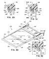
- Each side portion includes an integral, molded guide flange 220 (Figs. 29 and 31) on the outer side for engaging the vertical side surface of brackets 132'' to guide sliding movement.
- lower slide surfaces 222 of side portions 216, 218 include a pair of spaced, double-headed stud inserts 224 embedded therewithin generally in the center and at the rear of each side portion.
- Each stud insert 224 includes cylindrical body 226 adapted to be received through and between the parallel side edges of slots 206 to guide the sliding movement of the shelf member 201 in conjunction with flanges 220.
- a disc-shaped head 228 embedded within side portion 226 at a position spaced below the perimeter edge of glass panel 211 to resist withdrawal of the stud.
- a similar disc-shaped head 230 which extends below support flange 138'' and slots 206.
- shelf member 201 may be mounted on shelf support frame 202 by placing shelf member 201 in registry with support flanges 138'' such that heads 230 of inserts 224 are aligned with enlarged openings 210. Shelf member 201 is then moved downwardly such that sliding surfaces 222 engage support flanges 138'' while heads 230 extend through openings 210 of slots 206.
- shelf member 201 may be grasped and slid forwardly on its slide support surfaces and flanges 138'' until bodies 226 of inserts 224 engage forward ends 208 of slots 206 to limit further extension.
- rearward movement of the shelf is limited by engagement of heads 230 with studs 204 on cross member 136'' in the retracted position of the shelf.
- items to be refrigerated are fully and adequately supported on panel 211 while flanges 220 and bodies 226 guide the sliding movement and heads 230 prevent lifting of the shelf member 201 from the support frame 202 in all positions including the extended position except the retracted position shown in Figs. 31 and 32.
- the manufacturing method incorporates the use of a reusable, rigid mold insert or core 250 which is generally similar in shape to L-shaped support brackets 20a, 20b and 132.
- Core 250 is preferably formed from a ferro-magnetic material such as steel, preferably includes a corrosion preventing coating such as zinc-dichromate, has a generally planar, retaining body 252 and an integral, laterally extending flange 254 extending along the full length of body 252 at one edge.
- Flange 254 defines a slide channel forming portion which tapers to a thinner, free end edge 256.
- Core body 252 includes a series of spaced, apertures 258 used in manufacturing the core, as well as positioning apertures 260 adapted to receive positioning pins 314 for precisely locating the core within a mold apparatus as explained below.
- Mold 275 includes a lower mold section 280 including a central recess 282 receiving a vertically reciprocable pressure pad or plate 284 preferably mounted on springs and guide bolts (not shown) and having a glass support surface 286.
- Lower section 280 also includes lateral slide recesses 290 at either side.
- Cooperating with lower mold section 280 is an upper mold section 292 having a lower surface 293 defining a parting line and an upper glass engaging and clamping surface 294.
- glass engaging surface 294 of upper mold section 292 and glass support surface 286 of pressure pad 284 support, clamp and hold a planar sheet of glass such as panel 12, 102, 162 or 211 described above.
- a slide 306 mounted on a cylinder rod 308 of a pneumatic or hydraulically operated fluid cylinder (not shown).
- Rod 308 is preferably fixed in a stationary position by threaded end 309 while slides 306 and fluid cylinders move inwardly and outwardly together when the fluid cylinders are operated.
- lower mold section 280, upper mold section 292, pressure pad 284 and slides 306 define a pair of mold cavities 312 adapted for forming the side portions 44, 46 or 112 of shelf members 11, 101 described above. Mold cavities 312, of course, extend continuously into other portions of the upper and lower mold sections to define extensions thereof for forming the front and rear portions 40, 42 of the shelf members as is conventionally known in the molding industry.
- mold insert cores 250 are adapted for insertion with their slide channel forming sections 254 positioned within mold cavities 312, their retaining portions 252 extending outwardly and downwardly from the mold cavities for engagement by slides 306 including spring-biased positioning pins 314.
- Pins 314 extend through positioning apertures 260 after cores 250 are positioned against the side surface of the lower mold section and held in place by magnets 316.
- pins 314 accurately and precisely position the cores with respect to the perimeter edge of glass sheets 12, 102 such that the glass sheet perimeter edge will be spaced above section 254 and be properly embedded within the mold material in cavity 312 while retaining portion 252 will extend downwardly out of the molded rim portion, as shown in Figs. 36 and 37.
- the manufacturing process for producing shelf members 11, 101 will be understood. Initially, upper mold section 292 is moved away from lower mold section 280.
- both core inserts 250 are loaded manually or with the same robot arm by swinging them in against the side surfaces of the lower mold section beneath mold cavities 312 until magnets 316 grasp and hold the cores in position as shown in Fig. 36.
- the robot arm is moved out of the open mold assembly followed by closing of the mold.
- Both the upper and lower mold sections are preferably heated or cooled as necessary via internal fluid lines and heated or cooled water pumped therethrough to maintain a constant temperature during the molding operation.
- the preferred thermoplastic copolymer of ethylene and propylene mentioned above is injected into mold cavities 312.
- Injection is preferably made using a conventionally known hot runner injection system. Alternately, conventionally known sub gating, cold drop gating or edge gating injection methods can be used.
- Injection of the molten moldable material which is preferably heated during injection is made through small orifices, preferably at two or four positions on the underside of the front and rear portions of the shelf members such as at position A shown in Fig. 5. After injection, the moldable material is allowed to solidify and cure during a dwell time preferably of 10 to 15 seconds.
- slides 306 are moved outwardly by their associated fluid cylinders and the mold 275 is opened by raising the upper mold section 292.
- an ejector plate (not shown) engages suitable stops positioned to halt further movement of the ejector plate while upper mold section 292 continues to its final position. Consequently, the shelf assembly including the molded side portions in cavities 312 and glass plate 12, 102 is moved downwardly away from the mold cavity portions in upper mold half 292 while being held by suitable vacuum cups (not shown) on upper mold section 292. Simultaneously, other vacuum cups (not shown) on lower mold section 280 are opened to atmosphere to release the glass panel. Subsequently, the robot arm is moved into the open mold assembly carrying a new glass panel and a fresh pair of spaced reusable cores 250 to retrieve the completed shelf member and position the new glass panel and core members as described above.
- cores 250 After removal of the molded shelf member from the mold 275, cores 250 remain embedded within the molded side portions 44, 46, 112, as shown in Fig. 37. While the moldable material is still warm and relatively flexible and pliable, cores 250 are slid out of the slide channels 48, 114 in the molded side portions using a rolling motion, either manually or in a fixture. If a fixture is used, the shelf assembly is mounted upsidedown and pneumatic or hydraulic cylinders are moved to engage the outer surfaces of the cores to move them in a rolling motion in the direction shown by the arrow in Fig. 37. Removal of the slide channel forming sections 254 of cores 250 leaves slide channels 48, 114 integrally molded as described above for receipt of the support surfaces of the shelf support frame in the manner indicated.
- Manufacture of the shelf members 150, 200 may be accomplished in a similar mold apparatus to that shown at 275. Instead of positioning reusable cores 250 in the mold cavities, rigid inserts 168 or 224 are positioned to extend into the mold cavities for proper embedding within the molded rim portion in the manner described above.
- mold 275 may also be used to form a fixed, stationary shelf wherein fixed support brackets similar to brackets 20a, 20b or 132 are substituted for cores 250 in mold cavities 312. Such brackets remain in the molded side portions after removal from the mold. Accordingly, the molded sliding shelves made according to this method will have substantially the same overall appearance as a fixed shelf when made in the same mold apparatus.
Landscapes
- Engineering & Computer Science (AREA)
- Mechanical Engineering (AREA)
- Manufacturing & Machinery (AREA)
- Chemical & Material Sciences (AREA)
- Combustion & Propulsion (AREA)
- Physics & Mathematics (AREA)
- Thermal Sciences (AREA)
- General Engineering & Computer Science (AREA)
- Moulds For Moulding Plastics Or The Like (AREA)
- Freezers Or Refrigerated Showcases (AREA)
- Injection Moulding Of Plastics Or The Like (AREA)
- Refrigerator Housings (AREA)
Description
- This invention relates to shelving especially adapted for use in refrigerator compartments, especially refrigerators for food products, and more particularly, to a sliding shelf assembly for refrigerators having improved weight supporting capabilities, improved sliding movement, and an improved method for manufacturing.
- Many varieties of sliding refrigerator shelving have been used in the past. Typically, such sliding shelves include a shelf panel mounted for horizontal sliding extension toward the user through the door opening of the refrigerator to provide better access to items stored on the shelf or for ease in cleaning. One prior shelf includes a plurality of preformed frame members assembled around a shelf panel and slidably secured on appropriate support brackets. In another, tracks on opposite side surfaces guide sliding movement of the shelf panel.
- In certain of the prior known sliding shelves, difficulty in extending and retracting the shelf was experienced, especially when the shelf was heavily loaded with articles for refrigeration. In some cases, uneven extension required additional effort, while in others, the support strength in the extreme extended position, was less than desired.
- In addition, many prior known sliding shelf assemblies required manufacture from a number of individually fabricated pieces increasing manufacturing time and expense. Such shelves would not contain liquids if spilled, and thus would not limit contamination of the refrigerator or cabinet in the event a container was overturned. In many prior known molded shelves, specialized mold apparatus was required and the appearance of the sliding shelf assembly was often different from the standard, fixed shelves used adjacent to the sliding shelves in the same refrigerator.
- EP-A-0507455 discloses a moulded refrigerator shelf which has a planar shelf member with a rim. The shelf is slidably mounted and cantilevered on two side support brackets to allow extension of the shelf for easy access to the rear of the shelf. Because the shelf is cantilevered air is allowed to flow around the shelf sides.
- Accordingly, a need has existed for an improved sliding shelf assembly for refrigerators which would control and help confine spillage of liquids or other food items while providing improved sliding characteristics even when heavily loaded, increased support strength in both the extended and retracted positions, a similar appearance to standard, fixed position shelving used in the same refrigerator, and improved, simplified manufacturing techniques reducing manufacturing time and expense.
- The present invention is defined in the accompanying independent claims. Preferred features are recited in the dependent claims.
- The present invention provides a shelf assembly for refrigerated compartments, and especially refrigerators for food products, in which a shelf member is slidably mounted for extension and retraction on a shelf support, the shelf member including side members which are molded in one piece on an article support surface from a moldable material while incorporating either a molded guide member or an embedded insert which guides sliding movement and restricts vertical movement of the shelf with respect to the support. One of several varieties of a stop member for limiting extension or retraction is included. The invention also encompasses a manufacturing method including the provision of a rigid core having a portion embedded within the molded slide member, which core is withdrawn after molding to provide a slide channel avoiding the necessity of assembling the slide member from multiple parts and also allowing use of the same mold cavity used to form fixed refrigerator shelf versions.
- In one form the invention provides a shelf assembly for a refrigerated compartment as defined in
claim 1. - Preferably, the shelf support includes a pair of spaced, parallel, L-shaped support brackets each having a body and a laterally extending flange extending at a right angle to the body, the flange having a generally horizontal top surface forming the shelf support surface.
- A further development of the sliding shelf assembly according to the invention comprises:
- a generally planar shelf member having a top surface for supporting articles to be refrigerated, and a perimeter edge;
- a rim molded from a moldable material around the perimeter edge, the rim including generally parallel side portions extending along opposite portions of the perimeter edge of the shelf member, each side portion including a slide channel molded therewithin, the slide channels each defining a slide surface, a molded guide member for guiding sliding movement of the shelf assembly, and an opening through which a shelf support is received for engagement with the slide surface; and
- a stop on the rim for engaging a portion of a shelf support to limit sliding travel of the shelf assembly when mounted on a shelf support.
-
- The assembly may include a second molded guide member defined by the slide channel on the side portion, the guide members on each side portion being spaced laterally from and extending parallel to one another and depending downwardly adjacent the slide surface. The slide channel may be spaced from and extends generally parallel to the shelf member.
- Preferably, the slide channel is aligned with and below the perimeter edge of the shelf panel.
- Preferably, the shelf panel is glass and the moldable material is a resinous thermoplastic copolymer.
- In one form the slide channel is adapted to receive a slide support flange of a support bracket, the slide channel being oversized and larger than the support flange to allow sliding movement therebetween.
- Also according to a further development of the invention there is provided a shelf assembly for a refrigerated compartment comprising:
- a shelf support including a pair of spaced, generally horizontal, generally parallel, shelf support surfaces, a guide surface on each shelf support surface extending at an angle to the shelf support surface, and at least one mounting member adapted to mount the shelf support in a refrigerated compartment;
- a shelf member slidably mounted for extension and retraction on the shelf support, the shelf member including an article support surface and a pair of spaced side members, the side members being molded in one piece on the article support surface from a moldable material and extending along opposite sides of the article support surface, each side member including a slide surface slidably engaging one of the shelf support surfaces, at least one of the side members including a rigid member having a first portion embedded within the side member, and a second portion positioned along the guide surface and under one of the shelf support surfaces to guide sliding movement and restrict vertical movement of the shelf member, the extending portion of the rigid member including a stop thereon; and
- the shelf support also including an elongated opening for receiving and allowing movement of the stop when the shelf member is slidably extended or retracted, and at least one limit surface for engaging the stop member to limit at least one of the extension or retraction of the shelf member.
-
- The rigid member may be a stud embedded in the slide surface of the side member. At least one of the shelf support surfaces may include a slot forming the elongated opening; the stud projecting into the slot; the slot having at least one closed end defining the limit surface. In one form, the stud includes spaced, laterally extending flanges, one stud flange being embedded in the molded side member, the other stud flange extending under the shelf support surface.
- In a further development, the invention is a shelf assembly for a refrigerated compartment including a shelf support and a shelf member slidably mounted for extension and retraction on the shelf support. The shelf support includes a pair of spaced, generally horizontal, generally parallel shelf support surfaces and a guide surface extending at an angle to each shelf support surface. At least one mounting member is adapted to mount the shelf support in a refrigerated compartment. The shelf member includes a pair of spaced side members molded in one piece on an article support surface from a moldable material, the side members extending along opposite sides of the article support surface. Each side member includes a slide surface engaging one of the shelf support surfaces. At least one of the side members has a depending guide member adjacent the guide surface to guide sliding movement of the shelf member, the guide member also including a stop. The shelf support also includes an elongated opening for receiving and allowing movement of the shelf when the shelf member is slidably extended or retracted and at least one limit surface for engaging the stop member to limit at least one of the extension and retraction of the shelf member.
- In preferred aspects of the invention, the guide member and stop are molded integrally and in one piece with the side member while a second guide member is also molded on each side member to confine the shelf support surface for proper sliding movement. The guide members and slide surface are defined by a slide channel which, in the preferred form, is formed by the preferred method set forth herein.
- In other preferred aspects, the guide member and stop may be formed by a rigid insert embedded within the molded side member during molding and having a portion extending downwardly from the side member along and under the shelf support to restrict sliding and vertical movement of the shelf. Such rigid insert can be either a U-shaped member or a headed stud.
- Preferably, the shelf support includes a pair of L-shaped support brackets, each including a vertical body and a laterally extending flange, the flange having a top surface forming the shelf support surface. The limit surface may be formed either on the L-shaped bracket or on a cross member spacing the L-shaped bracket members apart. In the version incorporating the headed stud guide member, a slot is formed in the flange of the L-shaped bracket receiving the stud for both guiding and limiting sliding movement.
- In another aspect of the invention, a method for making a sliding shelf as defined in
claim 18 includes the provision of a rigid core having a slide channel forming portion thereon. The core is inserted in a mold apparatus such that the slide channel forming portion is located in the mold cavity. A slide member is molded from moldable material on an article support surface in the mold cavity while embedding the slide channel forming portion in the slide member. The molded slide member is then removed from the mold cavity with the slide channel forming portion remaining embedded within the slide member. Thereafter, the slide channel forming portion of the core is withdrawn from the slide member to form a channel within the slide member, the channel adapted to receive a slide support for sliding movement of the shelf. - In preferred aspects of the method, injectable polymeric material, such as a thermoplastic copolymer, is injected around the slide channel forming portion while a retaining portion of the core extends out of the slide member to form an opening to the slide channel. Preferably, the article supporting surface is formed by a glass panel member having a perimeter edge simultaneously embedded within the slide member when the core is embedded therein. The core may then be rotated and slid out of the molded side member to complete the manufacture.
- In its various forms, the present invention provides numerous advantages over prior known sliding shelf assemblies for refrigerators. The shelf assembly includes molded side members integrally incorporating a molded slide channel having guide members which allow smooth, uniform sliding extension and retraction of the shelf even when heavily loaded and without bothersome ratcheting or stuttering during sliding movement. Such construction maximizes available shelf space for storage while maintaining smooth shelf operation. The molded rim effectively controls and confines spilled liquids or other items on the shelf and is tightly sealed to the shelf panel to prevent unsanitary seepage between the rim and panel. The combination of support brackets and molded slide surfaces along with guide members which extend under the slide support surfaces prevent tipping, lifting or vertical movement of the shelf to allow the support of greater loads in both the extended and retracted positions. Manufacture of the sliding shelf is simplified through the use of a mold apparatus which allows embedding of a reusable core which can be withdrawn from the molded shelf after molding to leave a molded slide channel ready for installation on the shelf support (see method of claim 18). Alternatively, rigid inserts can be positioned in the mold cavity for embedding within the molded shelf to provide the guide members and stops allowing improved sliding movement (see method of claim 25). In addition, the method allows use of the same mold apparatus used to manufacture fixed, stationary shelf assemblies simply by the inclusion or omission of the core or rigid inserts and substitution of appropriate fixed shelf support members in the mold cavity.
- The present invention can be put into practice in various ways some of which will now be described by way of example with reference to the accompanying drawings, in which:
- Fig. 1 is a top perspective view of a first embodiment of the sliding shelf assembly of the present invention;
- Fig. 2 is a top perspective view of the shelf support frame for the shelf assembly of Fig. 1;
- Fig. 3 is a side elevation of the shelf assembly of Fig. 1;
- Fig. 4 is a fragmentary, sectional view taken along plane IV-IV of Fig. 3;
- Fig. 5 is a fragmentary, plan view of a front corner of the shelf assembly taken in area V of Fig. 1 with portions broken away;
- Fig. 6 is a sectional side elevation of the front area of the shelf assembly taken along plane VI-VI of Fig. 1;
- Fig. 7 is a fragmentary, sectional view taken along plane VII-VII of Fig. 3;
- Fig. 8 is a sectional view taken along plane VIII-VIII of Fig. 1;
- Fig. 9 is a fragmentary plan view of a rear portion of the shelf assembly taken along plane IX-IX of Fig. 3;
- Fig. 10 is a side view of a molded limit member for use with the shelf assembly of Fig. 1;
- Fig. 11 is an end elevation of the limit member of Fig. 10;
- Fig. 12 is a sectional side elevation of the limit member of Figs. 10 and 11;
- Fig. 13 is a sectional view of the shelf assembly showing the limit member inserted and taken along plane XIII-XIII of Fig. 4;
- Fig. 14 is a side elevation of a second embodiment of the sliding shelf assembly of the present invention;
- Fig. 15 is a side elevation of the shelf assembly of Fig. 14 with the sliding shelf member in extended position;
- Fig. 16 is a fragmentary plan view of the shelf assembly of Fig. 15;
- Fig. 17 is a fragmentary, sectional view taken along plane XVII-XVII of Fig. 16;
- Fig. 18 is a fragmentary, sectional view taken along plane XVIII-XVIII of Fig. 16;
- Fig. 19 is a fragmentary, sectional view taken along plane XIX-XIX of Fig. 16;
- Fig. 20 is a fragmentary, sectional view taken along plane XX-XX of Fig. 16;
- Fig. 21 is a fragmentary, sectional view taken along plane XXI-XXI of Fig. 16;
- Fig. 22 is a top perspective view of a third embodiment of the sliding shelf assembly of the present invention;
- Fig. 23 is a fragmentary, exploded view of portions of the shelf assembly of Fig. 22;
- Fig. 24 is a fragmentary, sectional view taken along plane XXIV-XXIV of Fig. 22;
- Fig. 25 is a fragmentary, sectional view taken along plane XXV-XXV of Fig. 22;
- Fig. 26 is a top perspective view of the shelf assembly of Fig. 22 with the shelf member shown in extended position;
- Fig. 27 is a fragmentary, side elevation taken along plane XXVII-XXVII of Fig. 26;
- Fig. 28 is a fragmentary, top perspective, exploded view of a fourth embodiment of the shelf assembly of the present invention;
- Fig. 29 is a fragmentary, sectional view taken along plane XXIX-XXIX of Fig. 28;
- Fig. 30 is a top perspective view of the shelf assembly of Fig. 28 showing the shelf member in extended position;
- Fig. 31 is a fragmentary, sectional view taken along plane XXXI-XXXI of Fig. 30;
- Fig. 32 is a fragmentary, sectional view taken along plane XXXII-XXXII of Fig. 31;
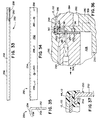
- Fig. 33 is a top plan view of a core member used in molding the shelf assemblies of Figs. 1-21;
- Fig. 34 is a side elevation of the core member of Fig. 33;
- Fig. 35 is an end elevation of the core member of Figs. 33 and 34;
- Fig. 36 is a sectional view of a preferred mold apparatus for making the shelf assemblies of Figs. 1-21; and
- Fig. 37 is a fragmentary, sectional view of the shelf member of Figs. 1-21 after molding but before removal of the embedded core.
-
- Referring now to the drawings in greater detail, Figs. 1-13 illustrate a
first embodiment 10 of a sliding refrigerator shelf assembly according to the present invention including a shelf member 11 having a generallyplanar shelf panel 12, a molded, resinous perimeter rim 14circumscribing shelf panel 12, and a rigid, shelf support frame 16 (Fig. 2) slidably supporting shelf member 11 for sliding movement between a retracted position (solid lines in Fig. 1) and an extended position (phantom lines in Fig. 1) in a refrigerated compartment such as a refrigerator for food products. Slidingshelf assembly 10 is preferably cantilevered forward bysupport frame 16 from a pair of spaced, vertical support tracks S (Fig. 1) mounted within the refrigerated compartment, each support track S including a plurality of aligned,vertical slots 15 adapted to receive mountinghooks support frame 16 as described hereinafter.Shelf 10 may, of course, be made in various widths, narrower or wider than that shown in Fig. 1, to accommodate desired refrigerator cabinet widths and various spacing of tracks S. - As is best seen in Figs. 2 and 3,
shelf support frame 16 includes a pair of laterally spacedside support brackets Brackets elongated body 22, and a laterally inwardly extendingsupport flange 23 extending at a right angle tobody 22 and having a generally planarshelf support surface 24 along the top edge of the bracket for the majority of its length. A front, reducedheight portion 26 on each bracket extends forwardly below the level of shelf support surfaces 24 to provide an access area for telescopingly inserting shelf member 11 thereon as described below. Therear end 28 of each L-shapedbracket Hooks slots 15 of vertical support tracks S (Fig. 1) whenshelf assembly 10 is mounted in a refrigerated compartment as mentioned above. Eachrear mounting portion 28 includes an offsetupper flange 34 adapted to be received within a molded recess at the rear of moldedrim 14 on shelf 11 as discussed below. The top surfaces 24 ofsupport flanges 23 are preferably co-planar and horizontal when supported in the refrigerator. Side edges 25 offlanges 23 and the side surfaces ofbodies 22 act as guide surfaces for shelf 11 during sliding movement. Thebody portion 22 of eachbracket circular opening 35 adapted to receive aslide limiting insert 72 as described below to restrict the forward sliding movement of shelf member 11 on theshelf support frame 16. A pair of spacedcircular apertures 37 allow the brackets to receive rivets or other fasteners for securing a pan or crisper support P (shown in phantom in Fig. 2) if desired. Support P would allow suspension of a slide-out pan or storage bin for meats, vegetables and produce, or the like. -
Brackets rigid cross members Brackets cross members Cross members opening 39 therebetween in the framework. Mounting hooks 30, 32, when engaged with vertical tracks S, fully support the shelf without the necessity of any additional supports extending from the sides of the refrigerated compartment into contact withbrackets Shelf support frame 16 preferably is powder-coated with an epoxy polyester coating, preferably white in color, sold under Product No. 071-30-06 by Herberts Powder Coatings Inc., of Hilliard, Ohio. The powder coating provides both a reduced friction, lubricous surface for shelf member 11 to slide on as well as providing protection from corrosion due to contact with spilled liquids, water and the like. Preferably, shelf support surfaces 24 are co-planar as shown in Fig. 2, although they could be positioned in offset planes depending on the design of the shelf member fitted thereon. - Referring now to Figs. 1 and 3-9,
shelf panel 12 is preferably a planar sheet of light transmitting material, such as optically clear tempered glass, to enhance light distribution through the refrigerated compartment.Panel 12 includes a perimeter edge 18 (Figs. 4 and 6) which is embedded and secured within moldedrim 14 generally above spacedsupport flanges 23 onbrackets shelf support frame 16 as shown in Fig. 4.Rim 14 is preferably molded around theentire perimeter edge 18 ofshelf panel 12.Rim 14 extends abovepanel 12 around the entire panel to confine spills and is molded for tight engagement and liquid sealing withpanel 12 to prevent seepage under the rim and between the glass and rim as is explained in commonly assigned United States Patent 5,362,145 issued November 8, 1994, entitled MOLDED REFRIGERATOR SHELF. Moldedrim 14 includes anintegral front strip 40, integralrear strip 42 and parallel side strips orportions shelf member 12 in a single molding operation, as is explained more fully below. The front, rear andside portions rim 14 each include moldedportions perimeter edge 18 ofpanel 12 to securely retain the panel in the shelf member. - Each molded
side portion slide channel 48 generally vertically aligned with theperimeter edge 18 ofshelf panel 12 but spaced therebelow by intermediate molded portions ofside portions slide channel 48 defines a pair of laterally spaced outer andinner guide flanges side portions Inner guide flange 52 also includes an integral laterally outwardly extendingflange 54 which extends under substantially the full extent offlange 23 onL brackets stop member 56 is molded integrally with and depends downwardly fromflange 54 at the rear of the shelf for engagement withshelf support frame 16 as is explained more fully below. Theupper surface 58 ofslide channel 48 is generally horizontal and parallel to theperimeter 18 ofshelf panel 12 and provides a slide surface adapted to engage thetop surface 24 offlange 23 to allow sliding movement of the shelf member 11 with respect to supportframe 16. Thefront end 55 ofslide channel 48 is closed (Fig. 5) while the rear of the channel opens into the area beneathrear strip 42 to allow insertion ofsupport flanges 23. As will be understood from Figs. 4 and 6, the size ofslide channel 48 is oversized and larger than the size offlange 23 and the upper portion ofvertical body 22 ofbrackets flanges brackets flanges 54. - As seen in Figs. 1, 5 and 6, the
front strip 40 of moldedrim 14 includes an outwardly and downwardly extendingflange 60 including anindicia area 62 for molding or imprinting of appropriate information, trademarks or the like. If desired,area 62 may include a recess for such information.Flange 60 includessides 64 which form a downwardly opening enclosure withflange 60 to house and shield the projecting ends 26 offrame 16 when the shelf member 11 is received thereover. Thelowermost edge 66 offront strip 40 provides a convenient area for grasping the shelf for extension and retraction. - As is best seen in Figs. 1, 3 and 7-9,
rear strip 42 of moldedrim 14 extends upwardly and rearwardly alongsurface 68 and includessides 70 forming a generally rearwardly opening enclosure which covers offsetedges 34 ofrear mounting portions 28 onbrackets - Preferably, rim 14 is formed from a moldable, resinous material such as a thermoplastic copolymer, most preferably TENITE™ polypropylene sold under Product No. P5M4K-007 by Eastman Plastics of Kingsport, Tennessee. Such material is a combination of ethylene and polypropylene, although other structural, resinous plastics, such as ABS or polyvinylchloride could be used. Preferably, a coloration pigment may be added to the moldable plastic used for molding
rim 14 prior to molding to provide a desired color to the rim. For example, titanium dioxide may be added for a white coloration. - While the liquid-tight seal formed between molded
rim 14 andglass shelf panel 12 performs well, depending on the specific resinous plastic chosen, one may wish to enhance that seal by coatingperimeter edge 18 of theglass panel 12 in the areas to be engaged by the molded rim with a primer layer or coating prior to molding of the rim. Such primer layer or coating is preferably a heat activatable, resinous material which promotes and facilitates the adhesion of the rim material to theglass shelf member 12. - With reference to Figs. 3, 4 and 10-13, a resilient, limit member or insert 72 is preferably received in opening 35 of each
bracket side 22 to limit the forward travel of the sliding shelf member 11 when extended. Preferably, insert 72 is molded from a resinous plastic material such as acetal, available from E. I. DuPont de Nemours Co., Wilmington, Delaware, and includes ahead 74 and a hollow,cylindrical body 76 extending perpendicularly from the underside ofhead 74.Body 76 includes a central,circular opening 77 and is notched at 78 to receive the thickness ofbracket body 22 when the insert is received inaperture 35, as shown in Fig. 13. As will be understood from Fig. 13, the height and length ofbody 76 is sufficient to extend into the path of moldedstop 56 wheninsert 72 is received inaperture 35 such that further forward sliding movement of shelf member 11 is limited by the engagement ofstop 56 andbody 76. The resiliency ofbody 76 allows it to compress and slide throughaperture 35 and snap outwardly into the position shown in Fig. 13. Moreover, should shelf member 11 be pulled outwardly with significant force,body 76 will bend slightly to absorb some of the energy as shelf member 11 is stopped against the limiting insert. - As will be best understood from Figs. 1-3, after manufacture, shelf member 11 is slidably telescopingly mounted on inwardly extending,
co-planar flanges 23 offrame 16 from the front edges of those flanges.Flanges 23 are received in the rearwardlyopening slide channels 48 and shelf 11 is slid rearwardly until the inside surface ofrear strip 42 is received against offsetareas 34 ofrear portions 28 ofbrackets insert 72 is pushed into place throughapertures 35. Forward extension of shelf member 11 is obtained by pulling onlip 66 offront strip 40 typically with a pull effort of 1 to 2 pounds, whileguide members slide surface 58 onflanges 23. Forward extension of shelf member 11 is limited by the engagement betweenstops 56 and inserts 72, as described above. In the extended position, items can be supported on the forward edge ofshelf 12 without fear of the shelf member 11 tipping forwardly and spilling the item due to the extent offlanges 54 underflanges 23 which restrict vertical movement of the shelf away from theshelf support frame 16. Shelf member 11 may then be retracted by pushing it inwardly usingfront strip 40 untilrear strip 42 engages offsetportions 34 ofrear mounting portions 28 as shown in Fig. 8. The vertical height ofrear strip 42 helps to catch and support any taller items which might tip rearwardly during sliding movement or storage of items on the refrigerator shelf. Preferably,shelf support frame 16 allowsshelf assembly 10 to be vertically adjusted within the refrigerator compartment on support tracks S. As noted above, hooks 30, 32 are adapted for releasable engagement with shelf tracks S to suspend the brackets, support frame and shelf assembly. The shelf assembly may be positioned at any one of a plurality of locations corresponding to the locations of the alignedslots 15 in the tracks. The overall size ofassembly 10 is preferably slightly smaller than the inside dimensions of the refrigerated compartment in which it is used to provide air circulation space between thesides 22 ofbrackets rear strip 42 and the rear wall of the refrigerator. Further, the overall length of shelf member 11 is determined to provide air circulation space between the front edge and the door of the refrigerator (not shown). - With reference to Figs. 14-21, a
second embodiment 100 of the sliding shelf assembly for refrigerated compartments is illustrated.Shelf assembly 100 is similar toassembly 10 but includes ashelf member 101 of slightly differing configuration having a moldedstop 122 adapted for engagement with a cross member on theshelf support frame 130, as explained more fully below. As shown in Figs. 14-16,shelf member 101 includes a generallyplanar shelf panel 102, preferably formed from optically clear tempered glass and an upstanding moldedrim 104 circumscribing theentire perimeter edge 106 ofshelf panel 102 and forming a liquid-tight seal therewith.Rim 104 includes parallel front andrear portions parallel side portions 112, all of which are molded integrally and in one piece onto theperimeter edge 106 ofpanel 102 in a suitable mold apparatus, as explained below. Just as in shelf member 11, moldedrim 104 includes an integral slide channel 114 (Fig. 19) molded beneathperimeter edge 106 to include spaced, lateral outer andinner guide flanges flange 120 extending fromguide flange 118. As shown in Figs. 14, 15, 20 and 21, anelongated stop member 122 is molded integrally with and depends downwardly from the bottom surface offlange 120 at a position flush with the inner side ofside portion 112. Stop 122 tapers rearwardly such that its bottom edge is inclined upwardly toward the rear ofshelf 101 to enable telescopic mounting of the shelf member onsupport frame 130. Theforward edge 124 ofstop 122 extends downwardly a distance sufficient to engage the rear edge of across member 134 on the support frame, as explained below.Shelf member 101 may be extended and retracted by grasping the downwardly extendinglip 126 onfront portion 108 as shown in Fig. 20. Just as inassembly 10,slide channel 114 is oversized and larger than thesupport flange 138 fromsupport bracket 132 adapted to be fitted therewithin to allow ease in sliding movement. Likewise,flanges lower flange 120 prevents lifting or tipping of the shelf when extended or retracted. - As will be understood from Figs. 14-16, a
shelf support frame 130 similar toframe 16 inassembly 10 is adapted for use withshelf member 101.Frame 130 includes a pair of L-shapedsupport brackets 132 which are spaced laterally and formed into a rigid framework by front and rear L-shapedcross members bracket 132 includes an inturned, generally planar,elongated flange 138. As shown in Fig. 21,flanges 138 are received in the rearwardlyopening slide channels 114 such that the top surfaces offlanges 138 engageslide surfaces 119 in the slide channels to allow extension and retraction ofshelf 101. Forward sliding movement ofshelf 101 is limited by engagement offront edge 124 ofstop 122 with the rear facing edge offront cross member 134 as shown in Fig. 20. During assembly, the clearance provided by the enlarged size ofslide channel 114 and the camming action provided by inclined bottom surface ofstop 122 allowshelf 101 to be cammed overcross member 134 until thefront edge 124 is received behind the cross member. As inassembly 10,brackets 132 also include mountinghooks 140 for mounting the assembly in a desired but vertically adjustable position on vertically extending support tracks such as those shown at S in Fig. 1. Also, moldedrim 104 is preferably formed from a thermoplastic copolymer of ethylene and polyethylene, preferably TENITE™ polypropylene P5M4K-007 sold by Eastman Plastics. Similarly,frame 130 includes brackets and cross members stamped from steel and welded together and powder-coated with epoxy polyester available from Herberts Powder Coatings Inc. of Hilliard, Ohio, under Product No. 071-30-06. - As shown in Figs. 22-27, a
third embodiment 150 of the sliding shelf assembly is illustrated where like parts are indicated by like prime numbers.Embodiment 150 preferably includes a modifiedshelf member 160 and a rigid steel and epoxy polyester powder-coated shelf support frame 130'. Frame 130' is substantially similar toshelf support frame 130 except for the addition of a downwardlybent limit flange 152 formed in support flange 138' and an upwardly extendinglimit stud 154 aligned with flange 138' in rear cross member 136'. -
Modified shelf member 160 includes a preferably optically clear temperedglass shelf panel 162 and a moldedrim 164 circumscribing the perimeter edge ofpanel 162 as inshelf members 11 and 101. As shown in Figs. 22 and 26, moldedrim 164 includes parallel front andrear portions parallel side portions entire panel 162 such that the perimeter is sealingly embedded therein. Preferably, moldedrim 164 is also formed from a thermoplastic copolymer of ethylene and propylene. Instead of the inclusion of an integral, molded slide channel beneath theperimeter edge 166 ofpanel 162, however,shelf member 160 includes rigid, downwardly depending,U-shaped inserts 168 embedded in the molded rim. -
Rigid inserts 168 are insert molded in spaced pairs in the lower slidingsurfaces side portions perimeter 166 of panel of 162, as shown in Figs. 24 and 25.Inserts 168 are U-shaped in section and include upper andlower flanges flange 182. When embedded within the side portion of the molded rim,flange 178 is spaced belowperimeter edge 166 and extends generally parallel thereto to resist removal of the insert from the molded side portion.Flange 182 extends generally perpendicular to theperimeter edge 166 whileflange 180 is generally parallel toflange 178 andpanel 162 but spaced below slidingsurface flanges 182 provide lateral guidance during sliding movement ofshelf member 160 on flanges 138', whileflanges 180 resist tipping and lifting of theshelf member 160 from the support frame. - As will be understood, the rear edge of
flange 180 on therearmost insert 168 is adapted to engagelimit stud 154 to limit rearward movement of theshelf member 160 on the support frame. Likewise, the forward edge offlanges 180 of the samerearmost inserts 168 are adapted to engagelimit members 152 to limit further extension when the shelf is pulled outwardly and extended. The area beneath flanges 138' and betweenlimit members flanges 180 ofinserts 168. Assembly ofshelf member 160 on rigid frame 130' is accomplished by telescopingshelf member 160 over flanges 138' with theflanges 180 ofinserts 168 in the positions shown in Figs. 24 and 25 beforelimit members 152 are bent downwardly from the support flanges 138'. After theshelf member 160 is in the position shown in Fig. 22,limit members 152 are bent downwardly to confine the shelf as described above. - As shown in Figs. 28-32, a
fourth embodiment 200 of the sliding shelf assembly of the present invention is illustrated where like parts are indicated by like numerals with the addition of double primes thereon.Shelf assembly 200 includesshelf member 201 slidably mounted for extension and retraction on a rigidshelf support frame 202.Shelf support frame 202 is similar to shelf support frames 130 and 130' and includes L-shaped support brackets 132'' spaced by rigid cross members 134'' and 136''. Rear cross member 136'' includes a slide limiting stud 204 (Figs. 31 and 32) which restricts rearward sliding travel ofshelf member 201 on the support frame as explained hereinafter. Instead ofbent limit member 152 as in support frame 130', however,shelf support frame 202 includes elongated, keyhole-shapedguide slots 206 extending through support flanges 138''. Eachguide slot 206 includes parallel side edges, a closedforward end 208 and an enlarged opening forming a closed,rear end 210. Brackets 132'' also include mounting hooks 140'' for securing theshelf support frame 202 and supportedshelf member 201 on suitable vertical support tracks such as those shown at S in Fig. 1. The entirerigid frame 202 is preferably powder-coated with epoxy polyester as in theearlier embodiments -
Shelf member 201 includes an optically clear,tempered glass panel 211 and a molded rim having parallel front andrear sections opposed side portions side portions stud insert 224 includescylindrical body 226 adapted to be received through and between the parallel side edges ofslots 206 to guide the sliding movement of theshelf member 201 in conjunction withflanges 220. At the upper end ofcylindrical body 226 is a disc-shapedhead 228 embedded withinside portion 226 at a position spaced below the perimeter edge ofglass panel 211 to resist withdrawal of the stud. At the lower end ofbody 226 is a similar disc-shapedhead 230 which extends below support flange 138'' andslots 206. - As will now be understood from Figs. 28-32, when inserts 224 are embedded in the sliding
surfaces 222 ofside portions shelf member 201 may be mounted onshelf support frame 202 by placingshelf member 201 in registry with support flanges 138'' such thatheads 230 ofinserts 224 are aligned withenlarged openings 210.Shelf member 201 is then moved downwardly such that slidingsurfaces 222 engage support flanges 138'' whileheads 230 extend throughopenings 210 ofslots 206. Thereafter,shelf member 201 may be grasped and slid forwardly on its slide support surfaces and flanges 138'' untilbodies 226 ofinserts 224 engage forward ends 208 ofslots 206 to limit further extension. Likewise, rearward movement of the shelf is limited by engagement ofheads 230 withstuds 204 on cross member 136'' in the retracted position of the shelf. In either case, items to be refrigerated are fully and adequately supported onpanel 211 whileflanges 220 andbodies 226 guide the sliding movement and heads 230 prevent lifting of theshelf member 201 from thesupport frame 202 in all positions including the extended position except the retracted position shown in Figs. 31 and 32. - With reference to Figs. 33-38, the preferred method for manufacturing the shelf members used in the
shelf assemblies core 250 which is generally similar in shape to L-shapedsupport brackets Core 250 is preferably formed from a ferro-magnetic material such as steel, preferably includes a corrosion preventing coating such as zinc-dichromate, has a generally planar, retainingbody 252 and an integral, laterally extendingflange 254 extending along the full length ofbody 252 at one edge.Flange 254 defines a slide channel forming portion which tapers to a thinner,free end edge 256.Core body 252 includes a series of spaced,apertures 258 used in manufacturing the core, as well aspositioning apertures 260 adapted to receivepositioning pins 314 for precisely locating the core within a mold apparatus as explained below. - With reference to Fig. 36, a preferred mold apparatus 275 for molding the
shelf members 11, 101 is shown. Mold 275 includes alower mold section 280 including acentral recess 282 receiving a vertically reciprocable pressure pad orplate 284 preferably mounted on springs and guide bolts (not shown) and having aglass support surface 286.Lower section 280 also includes lateral slide recesses 290 at either side. Cooperating withlower mold section 280 is anupper mold section 292 having alower surface 293 defining a parting line and an upper glass engaging and clampingsurface 294. Together,glass engaging surface 294 ofupper mold section 292 andglass support surface 286 ofpressure pad 284 support, clamp and hold a planar sheet of glass such aspanel - At either side of mold 275 in side recesses 290 is a
slide 306 mounted on acylinder rod 308 of a pneumatic or hydraulically operated fluid cylinder (not shown).Rod 308 is preferably fixed in a stationary position by threadedend 309 whileslides 306 and fluid cylinders move inwardly and outwardly together when the fluid cylinders are operated. In combination,lower mold section 280,upper mold section 292,pressure pad 284 and slides 306 define a pair ofmold cavities 312 adapted for forming theside portions shelf members 11, 101 described above.Mold cavities 312, of course, extend continuously into other portions of the upper and lower mold sections to define extensions thereof for forming the front andrear portions - As shown in Fig. 36,
mold insert cores 250 are adapted for insertion with their slidechannel forming sections 254 positioned withinmold cavities 312, their retainingportions 252 extending outwardly and downwardly from the mold cavities for engagement byslides 306 including spring-biased positioning pins 314.Pins 314 extend throughpositioning apertures 260 aftercores 250 are positioned against the side surface of the lower mold section and held in place bymagnets 316. Subsequently, as the fluid cylinders are activated to moveslides 306 inwardly against thecores 250, pins 314 accurately and precisely position the cores with respect to the perimeter edge ofglass sheets section 254 and be properly embedded within the mold material incavity 312 while retainingportion 252 will extend downwardly out of the molded rim portion, as shown in Figs. 36 and 37. Using the mold 275 as described above, the manufacturing process for producingshelf members 11, 101 will be understood. Initially,upper mold section 292 is moved away fromlower mold section 280. Either manually or with a robot arm preferably having vacuum cups holdingglass sheet cores 250 thereon, the glass panel is moved into the mold and loaded onglass support surface 286 ofpressure pad 284. The perimeter side edges of the glass sheet extend intomold cavities 312. Simultaneously, both core inserts 250 are loaded manually or with the same robot arm by swinging them in against the side surfaces of the lower mold section beneathmold cavities 312 untilmagnets 316 grasp and hold the cores in position as shown in Fig. 36. The robot arm is moved out of the open mold assembly followed by closing of the mold. Both the upper and lower mold sections are preferably heated or cooled as necessary via internal fluid lines and heated or cooled water pumped therethrough to maintain a constant temperature during the molding operation. After closure of the upper and lower mold sections, withglass panel surfaces 294 of the upper mold section and the glass support surfaces 286 of resiliently mountedpressure pad 284, the fluid cylinders are activated to moveslides 306 inwardly. During such movement, spring-biased positioning pins 314 engage taperedholes 260 at two locations on each core 250 to finally and precisely locate the cores such that slidechannel forming sections 254 are precisely positioned with respect to the perimeter edge ofglass panel - After loading of the glass and cores, the preferred thermoplastic copolymer of ethylene and propylene mentioned above is injected into
mold cavities 312. Injection is preferably made using a conventionally known hot runner injection system. Alternately, conventionally known sub gating, cold drop gating or edge gating injection methods can be used. Injection of the molten moldable material which is preferably heated during injection is made through small orifices, preferably at two or four positions on the underside of the front and rear portions of the shelf members such as at position A shown in Fig. 5. After injection, the moldable material is allowed to solidify and cure during a dwell time preferably of 10 to 15 seconds. Thereafter, slides 306 are moved outwardly by their associated fluid cylinders and the mold 275 is opened by raising theupper mold section 292. During such movement, an ejector plate (not shown) engages suitable stops positioned to halt further movement of the ejector plate whileupper mold section 292 continues to its final position. Consequently, the shelf assembly including the molded side portions incavities 312 andglass plate upper mold half 292 while being held by suitable vacuum cups (not shown) onupper mold section 292. Simultaneously, other vacuum cups (not shown) onlower mold section 280 are opened to atmosphere to release the glass panel. Subsequently, the robot arm is moved into the open mold assembly carrying a new glass panel and a fresh pair of spacedreusable cores 250 to retrieve the completed shelf member and position the new glass panel and core members as described above. - After removal of the molded shelf member from the mold 275,
cores 250 remain embedded within the moldedside portions cores 250 are slid out of theslide channels channel forming sections 254 ofcores 250 leaves slidechannels - Manufacture of the
shelf members reusable cores 250 in the mold cavities,rigid inserts - As will also be understood, mold 275 may also be used to form a fixed, stationary shelf wherein fixed support brackets similar to
brackets cores 250 inmold cavities 312. Such brackets remain in the molded side portions after removal from the mold. Accordingly, the molded sliding shelves made according to this method will have substantially the same overall appearance as a fixed shelf when made in the same mold apparatus. - While several forms of the invention have been shown and described, other forms will now be apparent to those skilled in the art, therefore, it will be understood that the embodiments shown in the drawings and described above are merely for illustrative purposes, and are not intended to limit the scope of the invention which is defined by the claims which follow.
Claims (27)
- A shelf assembly (10;100;150;200) for a refrigerated compartment, the shelf assembly comprising:a shelf support (16;130;130';130") including a pair of spaced shelf support surfaces (24;138;138';138"), a guide surface (25,206) on each shelf support surface extending at an angle to the shelf support surface, and at least one mounting member (30;32;140; 140';140") adapted to mount the shelf support in a refrigerated compartment;a shelf member (11;101;160;201) slidably mounted for movement on the shelf support, the shelf member including an article support surface (12;102;162;211) and a pair of spaced side members (44;46;112;174;176; 216;218), the side members being molded in one piece on the article support surface from a mouldable material and extending along opposite sides of the article support surface, each side member including a slide surface (58;119; 175;177;222) slidably engaging one of the shelf support surfaces, at least one of the side members having a guide member (52;118;182;226) to guide sliding movement of the shelf member along said guide surface, the one guide member including a stop (56;122;180;226) thereon,the shelf support also including an elongated opening (39,206) for receiving and allowing movement of the stop when the shelf member is slidably moved, and including at least one limit surface (76;134;152;208) for engaging the stop to limit the extent of travel of the shelf member in at least one direction of the sliding movement, said shelf support surfaces being generally horizontal and parallel to one another and extending inwardly and under said opposite sides of the article support surface and being received on said slide surfaces (58;119;175;177;222) which are spaced below, extend inwardly and are positioned beneath said opposite sides of the article support surface, each slide surface receiving one of the inwardly extending shelf support surfaces, each shelf support also including an undersurface, and the guide member including a laterally extending, lift restraining member (54;120;180;230) which extends under and immediately adjacent the shelf support undersurface and is adapted to engage the undersurface of the shelf support in the event that the shelf member is lifted, thereby restricting vertical movement of the shelf member with respect to the shelf support.
- A shelf assembly according to claim 1, wherein the shelf support includes a pair of spaced, substantially parallel support brackets (20a,20b), each bracket having one of the shelf support surfaces and one of the mounting members thereon.
- A shelf assembly according to claim 2, wherein each of the brackets is L-shaped and includes a body portion (22) and a laterally extending flange (23) arranged at a right angle to the body, the flange having a top surface forming the shelf support surface.
- A shelf assembly according to claim 3, wherein the flanges on the brackets extend inwardly toward one another.
- A shelf assembly according to any preceding claim, wherein the guide member and the stop member are moulded as a unitary structure with the one side member.
- A shelf assembly according to any of claims 3 to 5, wherein the one side member also includes a second guide member (50) moulded as a unitary structure therewith and spaced from the one guide member, and the side member includes a moulded channel (48) receiving the bracket flange and defining the guide members.
- A shelf assembly according to any of claims 2 to 6, wherein at least one of the brackets includes the limit surface, and the stop is adapted to engage the limit surface in one position of the shelf member.
- A shelf assembly according to any of claims 2 to 7, wherein the shelf support includes at least one cross member (134) extending between the brackets for spacing and supporting the brackets, the at least one cross member including the limit surface, the stop being adapted to engage a portion of the at least one cross member in one position of the shelf member.
- A shelf assembly according to any of claims 3 to 8, wherein the one guide member is a rigid member having one portion embedded within the moulded side member and a second portion extending downwardly from the side member and extending along and under the bracket flange.
- A shelf assembly according to claim 9, wherein the rigid member is a U-shaped insert (168) embedded in the slide surface of the side member, and the limit surface includes a limit member (152) on one of the brackets for engagement by the edge of the insert.
- A shelf assembly according to claim 10, wherein the insert extends around an edge of the flange in the space between the brackets, the stop including an edge of the U-shaped insert.
- A shelf assembly according to claim 9, wherein the rigid member is a stud (224) embedded in the slide surface of the side member.
- A shelf assembly according to claim 12, wherein the flange includes a slot (206) forming the elongate opening in the shelf support surface, the stud projecting into the slot, the slot having at least one closed end (208) defining the limit surface.
- A shelf assembly according to claim 12 or claim 13, wherein the stud includes spaced, laterally extending flanges (228,230), one stud flange (228) being embedded in the moulded side member, the other stud flange (230) extending under the bracket flange.
- A shelf assembly according to claim 14, wherein the slot includes an enlarged area (210) for receiving the other stud flange therethrough.
- A shelf assembly according to any preceding claim, wherein the shelf member includes a generally planar shelf panel (12;102;162;211) having a perimeter edge (18;106) thereon, and a rim (14;104;164;212,214,216,218) moulded and circumscribing the perimeter edge, the rim being moulded from a resinous polymeric material and including the side members , the side member including a flange moulded in one piece with the rim.
- A shelf assembly according to claim 16, wherein the stop is moulded as a unitary structure with the moulded side member flange on the guide member.
- A method of making a sliding shelf (10), comprising the steps of:providing a rigid core (250) having a slide channel forming portion (254) and a retaining portion (252);inserting the core (250) in a mould apparatus (280,284,292) defining a mould cavity (312) such that the slide channel forming portion is located in the interior of the mould cavity while the retaining portion extends out of the mould cavity of the apparatus;inserting a panel (12,102) of article support material in the mould apparatus such that a perimeter portion (18) of the panel extends into the interior of the mould cavity;positioning the core in a spaced relationship with the panel such that the slide channel forming portion is a predetermined distance from the perimeter portion of the panel; moulding a slide member by filling the mould cavity with a mouldable material, the mouldable material covering and embedding the perimeter portion of the panel in the slide member while also embedding the slide channel forming portion in the slide member, the moulding also including filling the space between the core and the panel with the mouldable material;removing the moulded slide member from the mould cavity with the slide channel forming portion and the perimeter portion of the panel remaining embedded within the slide member and the retaining portion extending from the slide member; andwithdrawing the slide channel forming portion of the core from the slide member by engaging the retaining portion of the core to form a channel within the slide member, the withdrawal of the slide channel forming portion of the core forming an opening to the channel, the channel being spaced from the perimeter edge of the panel, and the channel being adapted to receive a slide support (20) therein for sliding movement of the shelf.
- A method according to claim 18, wherein the withdrawing step includes rotating the core out of the slide member through the opening.
- A method according to claim 18 or claim 19, including inserting the core in the mould cavity such that the slide channel forming portion extends generally parallel to the perimeter portion of the panel member.
- A method according to any of claims 18 to 20, wherein the mouldable material is a thermoplastic copolymer.
- A method according to claim 21, wherein the copolymer is ethylene-propylene.
- A method according to any of claims 18 to 22, wherein the panel (12, 102) is made of glass.
- A method according to any of claims 18 to 23, including heating the mouldable material during injection.
- A method of making a sliding shelf (150,200) comprising the steps of :providing a mould apparatus (280,284,292) defining a mould cavity (312),inserting a panel (162,211) of article support material in the mould apparatus such that a perimeter portion (166) of the panel extends into the interior of the mould cavity,inserting a pair of rigid inserts (168;224) in the mould apparatus such that upper end portions (178,228) thereof are adjacent the perimeter portion (166) of the panel (162,211) along each of opposite substantially parallel side edges thereof,moulding a slide shelf member (160,201) by filling the mould cavity with mouldable material, the mouldable material covering and embedding the perimeter portion (166) of the panel (162,211) and the upper end portions (178,228) of the rigid inserts (168,224) in substantially spaced pairs along the opposite parallel side edges of the slide shelf member (160,201), the moulding also including encapsulating and thereby uniting the upper end portions (178,228) of the rigid inserts (168,224) to the opposite parallel side edges of the slide shelf member (160,201), andremoving the slide shelf member (160,201) from the mould, wherein the rigid insert includes a second portion (180,182,226,230) extending downwardly from the side edge of the slide shelf member and along and under the side edge forming a channel adapted to receive a slide support (130',202) therein for sliding movement of the shelf.
- A method according to claim 25 wherein the rigid inserts (168) are each of a generally U-shaped configuration.
- A method according to claim 25 wherein the rigid inserts (224) each comprise a stud including spaced, laterally extending flanges.
Applications Claiming Priority (2)
| Application Number | Priority Date | Filing Date | Title |
|---|---|---|---|
| US23662994A | 1994-04-29 | 1994-04-29 | |
| US236629 | 1994-04-29 |
Publications (2)
| Publication Number | Publication Date |
|---|---|
| EP0679848A1 EP0679848A1 (en) | 1995-11-02 |
| EP0679848B1 true EP0679848B1 (en) | 1999-07-07 |
Family
ID=22890308
Family Applications (1)
| Application Number | Title | Priority Date | Filing Date |
|---|---|---|---|
| EP95302593A Expired - Lifetime EP0679848B1 (en) | 1994-04-29 | 1995-04-19 | Sliding refrigerator shelf assembly |
Country Status (5)
| Country | Link |
|---|---|
| US (1) | US5735589A (en) |
| EP (1) | EP0679848B1 (en) |
| CA (1) | CA2146791C (en) |
| DE (1) | DE69510602T2 (en) |
| ES (1) | ES2133670T3 (en) |
Families Citing this family (130)
| Publication number | Priority date | Publication date | Assignee | Title |
|---|---|---|---|---|
| IT241539Y1 (en) * | 1996-01-22 | 2001-05-09 | Electrolux Zanussi Elettrodome | REFRIGERATOR EQUIPMENT EQUIPPED WITH SHELVES AND PERFECTED DRAWERS |
| US6116322A (en) * | 1996-09-30 | 2000-09-12 | Hunter Douglas Inc. | Control system for a vertical vane covering for architectural openings |
| US6105233A (en) * | 1997-10-29 | 2000-08-22 | Neal; Albert D. | Shelf for a refrigerator and method of making |
| US6592008B2 (en) * | 1998-08-17 | 2003-07-15 | Mario Dion | Dispenser apparatus |
| US6119678A (en) * | 1998-12-30 | 2000-09-19 | Gemtron Corporation | Appliance console including a glass touch sensor control panel bordered by a one-piece plastic encapsulation |
| US6164462A (en) * | 1999-09-28 | 2000-12-26 | L&P Property Management Company | Pull-out gravity feed shelf |
| US6227636B1 (en) * | 1999-11-15 | 2001-05-08 | Maytag Corporation | Refrigerator shelf and serving tray assembly |
| US6715166B1 (en) * | 2000-05-03 | 2004-04-06 | Grossman Product Services Sdn | Futon sofa bed |
| US6497185B1 (en) * | 2000-08-22 | 2002-12-24 | L&P Property Management Company | Slidable unit for modular shelving system |
| US6364136B1 (en) | 2000-09-18 | 2002-04-02 | Display Systems, Inc. | Sliding height-adjustable tray shelf unit |
| US6488347B1 (en) | 2000-11-21 | 2002-12-03 | Gemtron Corporation | Refrigerator shelf with one-piece internally ribbed/reinforced polymeric frame and reinforced suspension hooks |
| US6729704B2 (en) | 2000-12-22 | 2004-05-04 | General Electric Company | Removable glass encapsulated shelves |
| FR2822664B1 (en) | 2001-03-27 | 2004-07-02 | Saint Gobain | SHELF FOR THE SUPPORT OF ARTICLES, ESPECIALLY IN REFRIGERATED PLANTS |
| US20050280341A1 (en) * | 2001-03-27 | 2005-12-22 | Saint-Gobain Glass France | Shelf and frame for supporting a container, particularly in refrigerated installations |
| US6665984B2 (en) | 2001-06-13 | 2003-12-23 | Gemtron Corporation | Washer door or lid defined by a tempered glass panel bordered by an open frame-like encapsulation of one-piece injection molded polymeric/copolymeric synthetic plastic material |
| US6851776B2 (en) | 2001-06-28 | 2005-02-08 | Gemtron Corporation | Refrigerator compartment housing vertically adjustable shelves, each formed from a piece of tempered glass to which is injection molded a frame in the form of front and rear border members |
| US7568583B2 (en) * | 2001-07-16 | 2009-08-04 | Maytag Corporation | Upright rear wall extension for refrigerator shelves |
| WO2003012351A1 (en) * | 2001-08-01 | 2003-02-13 | Jimpa, Inc. | Appliance having shelving |
| CA2354917A1 (en) * | 2001-08-10 | 2003-02-10 | Valentine Joseph Wack | Stair bracket |
| DE10140006A1 (en) * | 2001-08-16 | 2003-02-27 | Bsh Bosch Siemens Hausgeraete | Refrigeration unit with a pull-out storage rack |
| US6923519B2 (en) * | 2001-12-04 | 2005-08-02 | Gsle Development Corp. | Blood bag support structure and method for refrigerators |
| US20030222043A1 (en) * | 2002-01-25 | 2003-12-04 | Eric Rouch | Adhesively bonded, leak-proof shelf |
| US7270385B2 (en) | 2002-02-12 | 2007-09-18 | General Electric Company | Spill proof shelf assembly method and structure |
| JP2003250674A (en) * | 2002-02-28 | 2003-09-09 | Sanden Corp | Shelf device of show case |
| GB0206930D0 (en) * | 2002-03-23 | 2002-05-08 | Univ Durham | Method and apparatus for the formation of hydrophobic surfaces |
| CN100414229C (en) * | 2002-06-06 | 2008-08-27 | 乐金电子(天津)电器有限公司 | Special storage cabinet for refrigerator containers |
| KR20040019597A (en) * | 2002-08-28 | 2004-03-06 | 젬트론 코포레이션 | A Washer Door or Lid Defined by a Tempered Glass Panel Bordered by an Open Frame-Like Encapsulation of One-Piece Injection Molded Polymeric/Copolymeric Synthetic Plastic Material |
| US7163305B2 (en) * | 2003-06-25 | 2007-01-16 | Gemtron Corporation | Illuminated shelf |
| US6766596B1 (en) * | 2003-07-14 | 2004-07-27 | Gemtron Corporation | Appliance door or lid |
| CN101438112B (en) * | 2004-10-15 | 2010-09-08 | 唐纳利公司 | Freezer Shelf Assembly |
| USD516100S1 (en) | 2004-11-15 | 2006-02-28 | Saint Gobain Glass France | Refrigerator shelf |
| USD525633S1 (en) | 2004-11-15 | 2006-07-25 | Saint Gobain Glass France | Refrigerator shelf |
| USD515598S1 (en) | 2004-11-19 | 2006-02-21 | Saint-Gobain Glass France | Refrigerator shelf |
| USD515599S1 (en) | 2004-11-22 | 2006-02-21 | Saint-Gobain Glass France | Refrigerator shelf |
| USD512732S1 (en) * | 2004-11-22 | 2005-12-13 | Saint-Gobain Glass France | Refrigerator shelf |
| USD525269S1 (en) | 2004-11-22 | 2006-07-18 | Saint-Gobain Glass France | Refrigerator shelf |
| USD517102S1 (en) * | 2004-11-22 | 2006-03-14 | Saint-Gobain Glass France | Refrigerator shelf |
| US7309116B2 (en) * | 2005-01-12 | 2007-12-18 | Whirlpool Corporation | Door mounted dairy compartment for a refrigerator |
| US7650757B2 (en) * | 2005-01-24 | 2010-01-26 | Delphi Technologies, Inc. | Thermoelectric heat transfer system |
| US8899704B2 (en) * | 2005-03-25 | 2014-12-02 | Gemtron Corporation | Refrigerator shelf |
| US20070075199A1 (en) * | 2005-04-15 | 2007-04-05 | Stewart Brian J | Wire sideplates |
| DE202005016883U1 (en) * | 2005-07-19 | 2006-11-23 | Liebherr-Hausgeräte Ochsenhausen GmbH | Fridge and / or freezer |
| US7748806B2 (en) * | 2005-08-29 | 2010-07-06 | Whirlpool Corporation | Encapsulated sliding shelf and over-molded frame |
| SE529351C2 (en) * | 2005-09-07 | 2007-07-17 | Sintek Internat Ab | Locking device at shelf rack |
| US7731316B2 (en) | 2006-06-09 | 2010-06-08 | Maytag Corporation | Universal shelf module for a refrigerator |
| KR100726453B1 (en) * | 2006-06-29 | 2007-06-11 | 삼성전자주식회사 | Refrigerator |
| US20080067909A1 (en) * | 2006-09-15 | 2008-03-20 | Norcold, Inc. | Shelf support arm with locking mechanism |
| US7748803B2 (en) * | 2006-10-02 | 2010-07-06 | Bradford Company | Horizontal dispensing container having multiple removable, sliding, hinged shelves |
| USD559281S1 (en) | 2006-12-14 | 2008-01-08 | Saint-Gobain Glass France | Refrigerator shelf |
| USD557293S1 (en) | 2006-12-14 | 2007-12-11 | Saint-Gobain Glass France | Refrigerator shelf |
| USD552636S1 (en) | 2006-12-14 | 2007-10-09 | Saint-Gobain Glass France | Refrigerator shelf |
| USD559280S1 (en) | 2006-12-14 | 2008-01-08 | Saint-Gobain Glass France | Refrigerator shelf |
| USD559282S1 (en) | 2006-12-14 | 2008-01-08 | Saint-Gobain Glass France | Refrigerator shelf |
| USD550727S1 (en) | 2006-12-14 | 2007-09-11 | Saint-Gobain Glass France | Refrigerator shelf |
| USD562854S1 (en) | 2006-12-14 | 2008-02-26 | Saint-Gobain Glass France | Refrigerator shelf |
| KR101342175B1 (en) * | 2007-01-05 | 2013-12-16 | 엘지전자 주식회사 | A shelf for refrigerator |
| US8231191B2 (en) | 2007-02-16 | 2012-07-31 | Saint-Gobain Glass France | Shelf for supporting articles, particularly in refrigerated installations |
| DE102007021596A1 (en) * | 2007-05-08 | 2008-11-13 | BSH Bosch und Siemens Hausgeräte GmbH | Profile, in particular extruded profile |
| US8414095B2 (en) * | 2008-01-23 | 2013-04-09 | Ssw Holding Company, Inc. | Full extension refrigerator shelf and basket system |
| FR2929814B1 (en) * | 2008-04-09 | 2010-08-27 | Saint Gobain | SHELF, ESPECIALLY FOR REFRIGERATED FACILITIES |
| FR2929811B3 (en) * | 2008-04-09 | 2010-08-27 | Saint Gobain | SHELF, ESPECIALLY FOR REFRIGERATED FACILITIES |
| MX2010013340A (en) * | 2008-06-04 | 2011-04-26 | Ssw Holding Co Inc | Shelf with led assembly. |
| KR100984453B1 (en) * | 2008-06-26 | 2010-09-29 | 엘지전자 주식회사 | Refrigerator |
| US11786036B2 (en) | 2008-06-27 | 2023-10-17 | Ssw Advanced Technologies, Llc | Spill containing refrigerator shelf assembly |
| MX345941B (en) | 2008-06-27 | 2017-02-27 | Ssw Holding Co Inc | Method for spill containment and shelves or the like therefore. |
| US8286561B2 (en) | 2008-06-27 | 2012-10-16 | Ssw Holding Company, Inc. | Spill containing refrigerator shelf assembly |
| US8926034B2 (en) | 2008-07-14 | 2015-01-06 | Lg Electronics Inc. | Refrigerator |
| FR2934481B1 (en) * | 2008-07-30 | 2011-01-14 | Saint Gobain | SHELF, ESPECIALLY FOR REFRIGERATED FACILITIES. |
| WO2010023305A1 (en) * | 2008-09-01 | 2010-03-04 | Arcelik Anonim Sirketi | A cooling device |
| EP2346678B1 (en) | 2008-10-07 | 2017-10-04 | Ross Technology Corporation | Spill resistant surfaces having hydrophobic and oleophobic borders |
| US9250010B2 (en) * | 2009-01-16 | 2016-02-02 | Whirlpool Corporation | Refrigerator shelf with glass receiving slot |
| GB2481835B8 (en) * | 2009-07-08 | 2012-07-25 | Keymed Medicals & Ind Equip | Shelving system |
| US20110030416A1 (en) * | 2009-08-07 | 2011-02-10 | Hoffman John S | Refrigerator Door Configuration |
| KR20110036446A (en) * | 2009-10-01 | 2011-04-07 | 삼성전자주식회사 | Shelf assembly of refrigerator and manufacturing method thereof |
| US8287062B2 (en) * | 2009-10-21 | 2012-10-16 | General Electric Company | Shelf for an appliance |
| ES2613885T3 (en) | 2009-11-04 | 2017-05-26 | Ssw Holding Company, Inc. | Cooking appliance surfaces that have a pattern of confinement of splashes and their manufacturing procedures |
| US20110115356A1 (en) * | 2009-11-18 | 2011-05-19 | Jonathan Nash | Shelf for an appliance |
| CA2796305A1 (en) | 2010-03-15 | 2011-09-22 | Ross Technology Corporation | Plunger and methods of producing hydrophobic surfaces |
| CN201844651U (en) * | 2010-10-21 | 2011-05-25 | 博西华家用电器有限公司 | Refrigerator and refrigerator shelf-retaining structure |
| CN101963434B (en) * | 2010-10-29 | 2012-04-04 | 无锡市超群自动化设备有限公司 | End part stopping card for slide rail of refrigerator |
| CN103476898A (en) | 2011-02-21 | 2013-12-25 | 罗斯科技公司 | Superhydrophobic and oleophobic coatings with low VOC binder systems |
| DE102011085428A1 (en) | 2011-10-28 | 2013-05-02 | Schott Ag | shelf |
| EP2791255B1 (en) | 2011-12-15 | 2017-11-01 | Ross Technology Corporation | Composition and coating for superhydrophobic performance |
| USD694292S1 (en) * | 2012-06-25 | 2013-11-26 | Sub-Zero, Inc. | Refrigerator shelf |
| EP2864430A4 (en) | 2012-06-25 | 2016-04-13 | Ross Technology Corp | ELASTOMERIC COATINGS HAVING HYDROPHOBIC AND / OR OLEOPHOBIC PROPERTIES |
| US8919146B2 (en) * | 2012-07-03 | 2014-12-30 | Electrolux Home Proucts, Inc. | Soft freeze zone |
| USD711437S1 (en) * | 2013-01-02 | 2014-08-19 | Samsung Electronics Co., Ltd. | Shelf for refrigerator |
| USD709532S1 (en) * | 2013-01-02 | 2014-07-22 | Samsung Electronics Co., Ltd. | Shelf for refrigerator |
| US9377578B2 (en) * | 2013-03-15 | 2016-06-28 | Whirlpool Corporation | Methods and apparatus to provide lighting in refrigerators |
| DE102013210893A1 (en) * | 2013-06-11 | 2014-12-11 | BSH Bosch und Siemens Hausgeräte GmbH | Domestic refrigerating appliance with an interior lighting device and translucent compartment dividers |
| KR20240127447A (en) | 2013-06-20 | 2024-08-22 | 젬트론 코포레이션 | Modular luminaires for appliance lighting |
| US10139152B2 (en) | 2013-10-03 | 2018-11-27 | Arcelik Anonim Sirketi | Refrigerator comprising a drawer |
| US9486090B2 (en) * | 2014-02-19 | 2016-11-08 | Southern Imperial, Inc. | Retail shelf |
| US9456691B2 (en) * | 2014-05-17 | 2016-10-04 | MALZINE Co. Ltd. | Structure to prevent drawer from falling off |
| US9335089B1 (en) | 2014-11-20 | 2016-05-10 | Electrolux Home Products, Inc. | Armless slide under shelf |
| USD807930S1 (en) | 2015-03-17 | 2018-01-16 | Whirlpool Corporation | Refrigerator shelf |
| US9593879B2 (en) | 2015-03-17 | 2017-03-14 | Whirlpool Corporation | U-shaped tuck shelf |
| USD808445S1 (en) | 2015-03-17 | 2018-01-23 | Whirlpool Corporation | Refrigerator shelf |
| USD810795S1 (en) | 2015-03-17 | 2018-02-20 | Whirlpool Corporation | Refrigerator |
| KR102369587B1 (en) * | 2015-08-17 | 2022-03-03 | 엘지전자 주식회사 | Weight balance of dish washer |
| USD809572S1 (en) | 2015-10-09 | 2018-02-06 | Whirlpool Corporation | Refrigerator shelf |
| USD808446S1 (en) | 2015-10-09 | 2018-01-23 | Whirlpool Corporation | Refrigerator shelf |
| DE102016202191A1 (en) * | 2016-02-12 | 2017-08-17 | BSH Hausgeräte GmbH | Appliances device |
| US10281197B2 (en) | 2016-10-11 | 2019-05-07 | Whirlpool Corporation | Quick shelf adjustment mechanism for a refrigerating appliance |
| KR102591763B1 (en) * | 2016-11-04 | 2023-10-23 | 삼성전자주식회사 | Refrigerator |
| USD841059S1 (en) | 2016-11-11 | 2019-02-19 | Whirlpool Corporation | Door bin |
| DE102017207221A1 (en) * | 2017-04-28 | 2018-10-31 | BSH Hausgeräte GmbH | Presentation of information on a cooling unit |
| BR102017009967B1 (en) | 2017-05-11 | 2024-02-20 | Whirlpool S.A. | HOUSEHOLD APPLIANCE EQUIPMENT COMPRISING SHELF ARRANGEMENT |
| US10655905B2 (en) | 2017-06-13 | 2020-05-19 | Whirlpool Corporation | Flexible compartment for a refrigerator |
| US10823480B2 (en) | 2017-08-01 | 2020-11-03 | Whirlpool Corporation | Air flow mechanism for compartment |
| US10677514B2 (en) | 2017-08-01 | 2020-06-09 | Whirlpool Corporation | Door bin with dual material and system lock |
| BR102017019233B1 (en) | 2017-09-08 | 2022-10-18 | Whirlpool S.A. | TRANSLATION SYSTEM FOR REFRIGERATOR SHELF |
| US10371436B2 (en) | 2017-11-08 | 2019-08-06 | Whirlpool Corporation | Bin assembly |
| US10808944B2 (en) | 2018-01-12 | 2020-10-20 | Whirlpool Corporation | Swinging rack |
| EP3759404A4 (en) | 2018-03-02 | 2022-06-08 | Electrolux Do Brasil S.A. | STORAGE STRUCTURE FOR REFRIGERATOR APPLICATION |
| AU2018410667B2 (en) * | 2018-03-02 | 2024-09-19 | Electrolux Do Brasil S.A. | Storage structure for refrigerator appliance |
| US10551071B2 (en) | 2018-05-11 | 2020-02-04 | Whirlpool Corporation | Oven rack system with removable support elements |
| US10914510B2 (en) | 2018-10-22 | 2021-02-09 | Whirlpool Corporation | Appliance mounting system |
| US11073329B2 (en) | 2018-10-31 | 2021-07-27 | Whirlpool Corporation | Refrigerator shelving frame with snap-in sliding insert |
| US10670327B1 (en) * | 2018-12-07 | 2020-06-02 | Bsh Hausgeraete Gmbh | Household cooling appliance comprising a shelf device |
| US10753674B1 (en) | 2019-02-20 | 2020-08-25 | Whirlpool Corporation | Refrigerator tuck shelf with flush profile and co-injected fixed glass |
| CN211270191U (en) * | 2019-07-26 | 2020-08-18 | 佛山市钜冠五金制造有限公司 | Lifting type baking net structure for oven |
| US10921050B1 (en) | 2019-10-10 | 2021-02-16 | Whirlpool Corporation | Support assembly for appliance |
| US12290174B2 (en) | 2020-04-24 | 2025-05-06 | Ssw Advanced Technologies, Llc | Illuminated shelf |
| CN113028725A (en) * | 2021-05-06 | 2021-06-25 | 青岛澳润商用设备有限公司 | Cantilever structure of refrigerator shelf enclosure frame |
| MX2024002924A (en) | 2021-10-15 | 2024-03-27 | Ssw Advanced Tech Llc | Illuminated shelf assemblies. |
| CA3232759A1 (en) | 2021-10-15 | 2023-04-20 | Ssw Advanced Technologies, Llc | Illuminated shelf assemblies |
| US12320578B2 (en) | 2023-04-06 | 2025-06-03 | Whirlpool Corporation | Refrigerator and corresponding shelving system |
| US12426709B1 (en) | 2024-09-10 | 2025-09-30 | Jay A. Berkowitz | Apparatus and method for releasably locked furniture |
| US12262812B1 (en) * | 2024-09-10 | 2025-04-01 | Jay A. Berkowitz | Apparatus and method for a releasably locked desktop in a modular cubicle |
Family Cites Families (24)
| Publication number | Priority date | Publication date | Assignee | Title |
|---|---|---|---|---|
| US2735741A (en) * | 1956-02-21 | Refrigerator shelf construction | ||
| US1830044A (en) * | 1930-03-31 | 1931-11-03 | Frigidaire Corp | Refrigerating apparatus |
| US1774312A (en) * | 1930-03-31 | 1930-08-26 | Frigidaire Corp | Refrigerating apparatus |
| US2093137A (en) * | 1934-01-17 | 1937-09-14 | Gen Motors Corp | Refrigerating apparatus |
| US2276942A (en) * | 1941-03-17 | 1942-03-17 | Willis B Dibble | Refrigerator shelf construction |
| US2306802A (en) * | 1941-08-20 | 1942-12-29 | Gen Electric | Food storage receptacle for refrigerators |
| US2519623A (en) * | 1947-08-20 | 1950-08-22 | B M Baker Engineers Inc | Drawer guide |
| US2689778A (en) * | 1951-04-16 | 1954-09-21 | Motor Products Corp | Refrigerator shelf mounting structure |
| US2759733A (en) * | 1951-08-21 | 1956-08-21 | Cushman Chuck Co | Expansible collet |
| US2876910A (en) * | 1955-12-14 | 1959-03-10 | Hoosier Cardinal Corp | Refrigerator shelf |
| US2997356A (en) * | 1959-04-01 | 1961-08-22 | Gen Electric | Sliding shelf |
| US3311072A (en) * | 1966-04-01 | 1967-03-28 | Gen Electric | Cantilever slide-out shelf |
| US3722974A (en) * | 1969-07-15 | 1973-03-27 | D Hartman | Drawer side wall |
| US3633983A (en) * | 1970-01-12 | 1972-01-11 | Philco Ford Corp | Shelf structure |
| GB1331493A (en) * | 1970-06-23 | 1973-09-26 | Hudson L G | Extendible runner |
| US3984163A (en) * | 1975-12-22 | 1976-10-05 | General Electric Company | Cantilever sliding shelf including a shelf removal notch on one side only |
| US4173378A (en) * | 1978-07-31 | 1979-11-06 | White Consolidated Industries, Inc. | Refrigerator sealed food storage drawer |
| JPS6068916A (en) * | 1983-09-26 | 1985-04-19 | Hashimoto Forming Co Ltd | Preparation of molding |
| DE3431666A1 (en) * | 1984-08-29 | 1986-03-20 | Karl-Heinz 7585 Lichtenau Meier | Process for producing boards with a plastic border |
| DE4038172A1 (en) * | 1990-11-30 | 1992-06-04 | Mecalit Gmbh | Prodn. of smooth lipping on boards - by placing board in injection mould, injecting polymer shot all round edges, injecting pressurised gas into shot and releasing gas pressure |
| US5362145A (en) * | 1991-03-07 | 1994-11-08 | Donnelly Corporation | Molded refrigerator shelf |
| US5441338A (en) * | 1991-03-07 | 1995-08-15 | Donnelly Corporation | Snap-on shelf |
| ATE392198T1 (en) * | 1992-05-12 | 2008-05-15 | Squibb & Sons Inc | OSTOMY COUPLING |
| US5340209A (en) * | 1992-12-28 | 1994-08-23 | General Electric Company | Slide-out shelf assembly for refrigerators |
-
1995
- 1995-04-11 CA CA002146791A patent/CA2146791C/en not_active Expired - Lifetime
- 1995-04-19 DE DE69510602T patent/DE69510602T2/en not_active Expired - Lifetime
- 1995-04-19 ES ES95302593T patent/ES2133670T3/en not_active Expired - Lifetime
- 1995-04-19 EP EP95302593A patent/EP0679848B1/en not_active Expired - Lifetime
- 1995-12-12 US US08/571,124 patent/US5735589A/en not_active Expired - Lifetime
Also Published As
| Publication number | Publication date |
|---|---|
| US5735589A (en) | 1998-04-07 |
| DE69510602D1 (en) | 1999-08-12 |
| ES2133670T3 (en) | 1999-09-16 |
| CA2146791C (en) | 2002-06-25 |
| CA2146791A1 (en) | 1995-10-30 |
| EP0679848A1 (en) | 1995-11-02 |
| DE69510602T2 (en) | 1999-12-30 |
Similar Documents
| Publication | Publication Date | Title |
|---|---|---|
| CA2146791C (en) | Sliding refrigerator shelf assembly | |
| US5660777A (en) | Method for making a sliding refrigerator shelf assembly | |
| EP0520786B1 (en) | Shelf for a refrigerated compartment | |
| EP0581419B1 (en) | Refrigerator shelf assembly | |
| EP0507455B1 (en) | Moulded refrigerator shelf | |
| US4143795A (en) | Refrigerator beverage dispensers | |
| US9389012B2 (en) | Rail door bin system | |
| CN101069054B (en) | Shelf, particularly for refrigeration units, which is designed to support at least one accessory and corresponding accessories | |
| CA2791811C (en) | Container with scooping utensil and scooping retainer in the closure | |
| CA1328903C (en) | Method and apparatus for retrofitting a drawer with a multiple level storage tray | |
| MXPA05002615A (en) | Heat staked shelf. | |
| WO2002035022A9 (en) | Bulkhead and partition systems | |
| CA2094836C (en) | Molded refrigerator shelf with snap-in slide | |
| US20050017143A1 (en) | Molded shelf | |
| US10330372B2 (en) | Rail door storage system | |
| KR20020041786A (en) | Refrigerator storage tray | |
| US20170321954A1 (en) | Retainer member | |
| EP0778115A1 (en) | Method for forming an object by means of injection moulding, and mould for application of the method | |
| CN215993447U (en) | Novel stainless steel seafood cabinet with sorting mechanism | |
| CA2228085C (en) | Article support | |
| US20230144852A1 (en) | Refrigerator Shelves | |
| JPH0519891U (en) | Internal shelves for refrigerators | |
| HK1178867B (en) | Container for storing material |
Legal Events
| Date | Code | Title | Description |
|---|---|---|---|
| PUAI | Public reference made under article 153(3) epc to a published international application that has entered the european phase |
Free format text: ORIGINAL CODE: 0009012 |
|
| AK | Designated contracting states |
Kind code of ref document: A1 Designated state(s): DE ES FR GB IT SE |
|
| 17P | Request for examination filed |
Effective date: 19960423 |
|
| 17Q | First examination report despatched |
Effective date: 19961122 |
|
| GRAG | Despatch of communication of intention to grant |
Free format text: ORIGINAL CODE: EPIDOS AGRA |
|
| GRAG | Despatch of communication of intention to grant |
Free format text: ORIGINAL CODE: EPIDOS AGRA |
|
| GRAG | Despatch of communication of intention to grant |
Free format text: ORIGINAL CODE: EPIDOS AGRA |
|
| GRAH | Despatch of communication of intention to grant a patent |
Free format text: ORIGINAL CODE: EPIDOS IGRA |
|
| RAP1 | Party data changed (applicant data changed or rights of an application transferred) |
Owner name: GEMTRON CORPORATION |
|
| GRAH | Despatch of communication of intention to grant a patent |
Free format text: ORIGINAL CODE: EPIDOS IGRA |
|
| GRAA | (expected) grant |
Free format text: ORIGINAL CODE: 0009210 |
|
| AK | Designated contracting states |
Kind code of ref document: B1 Designated state(s): DE ES FR GB IT SE |
|
| REF | Corresponds to: |
Ref document number: 69510602 Country of ref document: DE Date of ref document: 19990812 |
|
| ET | Fr: translation filed | ||
| REG | Reference to a national code |
Ref country code: ES Ref legal event code: FG2A Ref document number: 2133670 Country of ref document: ES Kind code of ref document: T3 |
|
| PLBE | No opposition filed within time limit |
Free format text: ORIGINAL CODE: 0009261 |
|
| STAA | Information on the status of an ep patent application or granted ep patent |
Free format text: STATUS: NO OPPOSITION FILED WITHIN TIME LIMIT |
|
| 26N | No opposition filed | ||
| REG | Reference to a national code |
Ref country code: GB Ref legal event code: IF02 |
|
| PGFP | Annual fee paid to national office [announced via postgrant information from national office to epo] |
Ref country code: GB Payment date: 20140428 Year of fee payment: 20 |
|
| PGFP | Annual fee paid to national office [announced via postgrant information from national office to epo] |
Ref country code: IT Payment date: 20140429 Year of fee payment: 20 Ref country code: ES Payment date: 20140428 Year of fee payment: 20 Ref country code: SE Payment date: 20140429 Year of fee payment: 20 Ref country code: FR Payment date: 20140417 Year of fee payment: 20 Ref country code: DE Payment date: 20140429 Year of fee payment: 20 |
|
| REG | Reference to a national code |
Ref country code: DE Ref legal event code: R071 Ref document number: 69510602 Country of ref document: DE |
|
| REG | Reference to a national code |
Ref country code: GB Ref legal event code: PE20 Expiry date: 20150418 |
|
| REG | Reference to a national code |
Ref country code: SE Ref legal event code: EUG |
|
| REG | Reference to a national code |
Ref country code: ES Ref legal event code: FD2A Effective date: 20150626 |
|
| PG25 | Lapsed in a contracting state [announced via postgrant information from national office to epo] |
Ref country code: GB Free format text: LAPSE BECAUSE OF EXPIRATION OF PROTECTION Effective date: 20150418 Ref country code: ES Free format text: LAPSE BECAUSE OF EXPIRATION OF PROTECTION Effective date: 20150420 |