EP0679782A1 - Key cylinder automatic returning device for cylinder lock device - Google Patents
Key cylinder automatic returning device for cylinder lock device Download PDFInfo
- Publication number
- EP0679782A1 EP0679782A1 EP95106456A EP95106456A EP0679782A1 EP 0679782 A1 EP0679782 A1 EP 0679782A1 EP 95106456 A EP95106456 A EP 95106456A EP 95106456 A EP95106456 A EP 95106456A EP 0679782 A1 EP0679782 A1 EP 0679782A1
- Authority
- EP
- European Patent Office
- Prior art keywords
- sleeve
- cylinder
- key cylinder
- shaft
- key
- Prior art date
- Legal status (The legal status is an assumption and is not a legal conclusion. Google has not performed a legal analysis and makes no representation as to the accuracy of the status listed.)
- Granted
Links
- 230000007935 neutral effect Effects 0.000 description 4
- 230000006378 damage Effects 0.000 description 2
- XLYOFNOQVPJJNP-UHFFFAOYSA-N water Substances O XLYOFNOQVPJJNP-UHFFFAOYSA-N 0.000 description 2
Images

Classifications
-
- E—FIXED CONSTRUCTIONS
- E05—LOCKS; KEYS; WINDOW OR DOOR FITTINGS; SAFES
- E05B—LOCKS; ACCESSORIES THEREFOR; HANDCUFFS
- E05B17/00—Accessories in connection with locks
- E05B17/04—Devices for coupling the turning cylinder of a single or a double cylinder lock with the bolt operating member
-
- E—FIXED CONSTRUCTIONS
- E05—LOCKS; KEYS; WINDOW OR DOOR FITTINGS; SAFES
- E05B—LOCKS; ACCESSORIES THEREFOR; HANDCUFFS
- E05B17/00—Accessories in connection with locks
- E05B17/0054—Fraction or shear lines; Slip-clutches, resilient parts or the like for preventing damage when forced or slammed
- E05B17/0058—Fraction or shear lines; Slip-clutches, resilient parts or the like for preventing damage when forced or slammed with non-destructive disengagement
-
- E—FIXED CONSTRUCTIONS
- E05—LOCKS; KEYS; WINDOW OR DOOR FITTINGS; SAFES
- E05B—LOCKS; ACCESSORIES THEREFOR; HANDCUFFS
- E05B9/00—Lock casings or latch-mechanism casings ; Fastening locks or fasteners or parts thereof to the wing
- E05B9/04—Casings of cylinder locks
- E05B2009/047—Means for returning cylinder locks to their neutral position
-
- E—FIXED CONSTRUCTIONS
- E05—LOCKS; KEYS; WINDOW OR DOOR FITTINGS; SAFES
- E05B—LOCKS; ACCESSORIES THEREFOR; HANDCUFFS
- E05B15/00—Other details of locks; Parts for engagement by bolts of fastening devices
- E05B15/04—Spring arrangements in locks
- E05B2015/0403—Wound springs
- E05B2015/042—Wound springs wound in a plane, e.g. spirally
-
- Y—GENERAL TAGGING OF NEW TECHNOLOGICAL DEVELOPMENTS; GENERAL TAGGING OF CROSS-SECTIONAL TECHNOLOGIES SPANNING OVER SEVERAL SECTIONS OF THE IPC; TECHNICAL SUBJECTS COVERED BY FORMER USPC CROSS-REFERENCE ART COLLECTIONS [XRACs] AND DIGESTS
- Y10—TECHNICAL SUBJECTS COVERED BY FORMER USPC
- Y10S—TECHNICAL SUBJECTS COVERED BY FORMER USPC CROSS-REFERENCE ART COLLECTIONS [XRACs] AND DIGESTS
- Y10S70/00—Locks
- Y10S70/36—Spring-returned lock cylinder
-
- Y—GENERAL TAGGING OF NEW TECHNOLOGICAL DEVELOPMENTS; GENERAL TAGGING OF CROSS-SECTIONAL TECHNOLOGIES SPANNING OVER SEVERAL SECTIONS OF THE IPC; TECHNICAL SUBJECTS COVERED BY FORMER USPC CROSS-REFERENCE ART COLLECTIONS [XRACs] AND DIGESTS
- Y10—TECHNICAL SUBJECTS COVERED BY FORMER USPC
- Y10T—TECHNICAL SUBJECTS COVERED BY FORMER US CLASSIFICATION
- Y10T70/00—Locks
- Y10T70/70—Operating mechanism
- Y10T70/7441—Key
- Y10T70/7486—Single key
- Y10T70/7508—Tumbler type
- Y10T70/7559—Cylinder type
- Y10T70/7638—Cylinder and plug assembly
-
- Y—GENERAL TAGGING OF NEW TECHNOLOGICAL DEVELOPMENTS; GENERAL TAGGING OF CROSS-SECTIONAL TECHNOLOGIES SPANNING OVER SEVERAL SECTIONS OF THE IPC; TECHNICAL SUBJECTS COVERED BY FORMER USPC CROSS-REFERENCE ART COLLECTIONS [XRACs] AND DIGESTS
- Y10—TECHNICAL SUBJECTS COVERED BY FORMER USPC
- Y10T—TECHNICAL SUBJECTS COVERED BY FORMER US CLASSIFICATION
- Y10T70/00—Locks
- Y10T70/70—Operating mechanism
- Y10T70/7441—Key
- Y10T70/7486—Single key
- Y10T70/7508—Tumbler type
- Y10T70/7559—Cylinder type
- Y10T70/7667—Operating elements, parts and adjuncts
- Y10T70/7706—Operating connections
- Y10T70/7712—Rollbacks
Definitions
- the present invention relates to a cylinder lock device and, more particularly, to a cylinder lock which high resistance to destruction, and in which a rotated key cylinder is automatically returned to the original position by a spring.
- the tumblers hold the key cylinder in the state of being engaged with the sleeve, to cause the key cylinder to be rotated together with the sleeve. Since the lock-piece operating member is not rotated, the lock device cannot be actuated.
- the key cylinder When an improper key is used in the above type of free-turn cylinder lock, the key cylinder is allowed to freely rotate; that is, it is impossible to apply rotational force strong enough to destroy the tumblers. Thus, the cylinder lock can have high resistance to destruction.
- An object of the present invention to provide a key cylinder automatic returning device for a free-turn lock device which automatically returns the proper key to the original position when the key cylinder is rotated by the proper key.
- a cylinder lock device to which the invention is directed comprises a case having a first housing, a sleeve rotatably incorporated in the first housing of the case and having a second housing and an engaging portion, a key cylinder rotatably incorporated in the second housing of the sleeve, and tumblers slidably arranged in the key cylinder and capable of engaging with the engaging portion of the sleeve.
- the key cylinder is rotated with respect to the sleeve when a proper key is inserted into the key cylinder and turned, and the key cylinder and the sleeve are rotated together when an improper key is inserted into the key cylinder and turned.
- a key cylinder automatic returning device for the above cylinder lock device comprises first and second case shafts projecting from the case; a cylinder shaft projecting from the key cylinder along a center line of the sleeve, and located between the first and second case shafts; and a spring coiled on the first case shaft, and having two legs between which the cylinder shaft and the second case shaft are placed.
- a sleeve central shaft projecting from the sleeve along a center line of the sleeve; a sleeve eccentric shaft deviated from the center line of the sleeve and projecting therefrom; a cylinder shaft deviated from the sleeve central shaft, projecting from the key cylinder, and located between the sleeve central shaft and the sleeve eccentric shaft; and a spring coiled on the sleeve central shaft, and having two legs between which the cylinder shaft and the sleeve eccentric shaft are placed.
- the spring When the key cylinder is rotated with respect to the sleeve by the proper key being inserted in the key cylinder, the spring imparts returning force to the cylinder shaft that is making an arcuate movement.
- the cylinder shaft is rotated around the center line of the sleeve between the two legs of the spring without deforming the spring.
- a sleeve shaft eccentric to the sleeve and axially projecting therefrom a cylinder shaft deviated from a center line of the key cylinder and axially projecting from the key cylinder; first and second case shafts eccentric to the case and axially projecting from the case; an inside lever rotatably attached to the sleeve shaft, and having a cut that fits with the cylinder shaft, and a lever shaft axially projecting along the center line of the key cylinder passing through a circular-arc groove formed in the case and located between the first and second case shafts; an outside lever rotatably attached to the first case shaft, and having a receptacle hole that fits with the lever shaft; and a spring coiled on the first case shaft, and having two legs between which the lever shaft and the second case shaft are placed.
- a cylinder lock device 1 has a case 3 provided with a first housing 7, a sleeve 4 that is rotatably incorporated in the first housing 7 of the case 3 and provided with a second housing 8, and a key cylinder 5 rotatably installed in the second housing 8 of the sleeve 4.
- a circular-arc groove 16 is formed in the case 3.
- Tumblers such as disk tumblers or pin tumblers are slidably arranged in the key cylinder 5 by the known method. The tumblers are engaged with an engaging portion that is, for instance, tumbler grooves or pin holes of the sleeve 4 so as to be separable therefrom.
- a key cylinder automatic returning device 2 of this cylinder lock device 1 is provided with a cylinder shaft 15 that projects from the key cylinder 5 along the central axis 20 of the sleeve 4 passing through the circular-arc groove 16 of the case 3, and a pair of case shafts 13a and 13b that project from the case 3.
- a spring 10 is coiled on the case shaft 13a.
- the cylinder shaft 15 is so disposed as to be closer to the case shaft 13a than the case shaft 13b.
- the cylinder shaft 15 and the case shaft 13b are placed between both legs 11 and 12 of the spring 10.
- a lever 31 that is rotatably supported by a through-hole 30 is fixed to the case shaft (pivot) 13a with a clip or the like (not shown).
- the lever 31 has a through-hole 33 into which the cylinder shaft 15 is inserted and an arm 32 for driving a lock device (not shown).
- the tumblers are disengaged from the engaging portion of the sleeve 4 and the key cylinder 5 is rotated relative to the sleeve 4.
- the cylinder shaft 15 makes an arcuate movement around the central axis 21 of the key cylinder 5 while being confined by the circular-arc groove 16 formed in the case 3.
- the arcuate movement of the cylinder shaft 15 causes the lever 31 to be rotated around the case shaft (pivot) 13a, so that the arm 32 locks or unlocks the lock device.
- the spring 10 When the cylinder shaft 15 is rotated to the locked position or the unlocked position, the spring 10 imparts returning force to the cylinder shaft 15 at a location between the fixed case shafts 13a and 13b. Therefore, when the rotational force is removed from the key in the locked or unlocked position, the key cylinder 5 can be automatically returned from the rotated position to the original position by resilient force of the spring 10.
- the key cylinder 5 and the sleeve 4 are rotated together around the central axis 20 of the sleeve 4 and the cylinder shaft 15 does not elastically deform the spring 10. That is, the cylinder shaft 15 is rotated on the central axis 20 of the sleeve 4 within the circular-arc groove 16 of the case 3 and between both legs 11 and 12 of the spring 10, without deforming the spring 10.
- Fig. 3 is a sectional view illustrating a second embodiment of the invention.
- the parts corresponding to those in Figs. 1 and 2 are given the same reference symbols and descriptions therefor will be omitted.
- a cylinder lock device 1 shown in Fig. 3 is provided with a sleeve central shaft 14a that projects from the sleeve 4 and extends along the center line of the sleeve 4, a sleeve eccentric shaft 14b that projects from the sleeve 4 at a position deviated from the center of the sleeve 4, a cylinder shaft 15 that projects from the key cylinder 5 at a position deviated from the sleeve eccentric shaft 14b and is closer to the sleeve central shaft 14a than the sleeve eccentric shaft 14b, and a spring 10 coiled on the sleeve central shaft 14a.
- a through-hole 33 for the lever 31 is arranged on the cylinder shaft 15.
- the cylinder shaft 15 is located closer to the sleeve central shaft 14a than the sleeve eccentric shaft 14b, and the cylinder shaft 15 and the sleeve eccentric shaft 14b are placed between both legs 11 and 12 of the spring 10.
- the tumblers are disengaged from the engaging portion of the sleeve 4 and the key cylinder 5 can be rotated relative to the sleeve 4.
- the cylinder shaft 15 makes an arcuate movement around the central axis 21 of the key cylinder 5, and the arm 32 is rotated around the central axis 21 to lock or unlock a lock device.
- the cylinder shaft 15 receives a returning force from the spring 10.
- Figs. 4-11 show a third embodiment of the invention.
- a sleeve 4 is provided with an engaging portion 9, and a tumbler 6 is slidably provided in each of a plurality of slits 5a of a key cylinder 5.
- the tumblers 6 project from the key cylinder 5, they can contact with the engaging portion 9 of the sleeve 4.
- a slot 40 is formed in the sleeve 4 in the radial direction, and a spring 42 and a ball 41 are placed in the slot 40.
- the ball 41 is pushed outward in the radial direction by resilience of the spring 42 against a V-shaped groove 43 that is formed in a case 3.
- the sleeve 4 and the key cylinder 5 are rotated together by an improper key, the sleeve 4 can be returned to the regular position by the ball 41 being engagement with the groove 43.
- the groove 43 serves as a water path to remove water that has been introduced into the cylinder lock 1.
- the cylinder lock 1 of this embodiment is provided with a sleeve shaft 14 eccentric to the sleeve 4 and projecting therefrom axially and a cylinder shaft 15 deviated from a central axis 21 of the key cylinder and axially projecting from the key cylinder 5 (see Fig. 5).
- the sleeve shaft 14 is inserted into a through-hole 17a of an inside lever 17, and the inside lever 17 is rotatably mounted on the sleeve shaft 14.
- the inside lever 17 is provided with a lever shaft 17c and a cut 17b that fits with the cylinder shaft 15.
- the lever shaft 17c projects axially along the central axis 21 of the key cylinder 5 passing through a circular-arc groove 16 formed in the case 3.
- the case 3 is provided with a pair of case shafts 13a and 13b both of which are deviated from the central axis 21 of the key cylinder 5 and extend axially.
- the case shafts 13a fits into a through-hole 18a of an outside lever 18 to rotatably support the outside lever 18.
- the outside lever 18 is provided with a receptacle hole 18b that fits with the lever shaft 17c, and a bracket 19 attached to the case shaft 13a prevents the outside lever 18 from falling off.
- a spring 10 is coiled on the case shaft 13a.
- the lever shaft 17c is located closer to the case shaft 13a than the case shaft 13b.
- the lever shaft 17c and the case shaft 13b are placed between both legs 11 and 12 of the spring 10.
- the inside lever 17 is rotated from the neutral position (see Fig. 6) to the operating position (locked position or unlocked position; see Fig. 8) around the sleeve shaft 14, and the outside lever 18 is rotated from the neutral position (see Fig. 7) to the operating position (locked position or unlocked position; see Fig. 9) around the case shaft 13a.
- a lock device can be locked or unlocked by the rotation of the cylinder shaft 15 through the action of the inside lever 17 and the outside lever 18.
- both legs 11 and 12 of the spring 19 impart returning force to the lever shaft 17c.
- the key cylinder 15 can be automatically returned from the rotated position to the original position by resilience of the spring 10 through the action of the inside lever 17.
- the key cylinder automatic returning device causes the key cylinder to automatically return to the original position when it is rotated by the proper key. Therefore, the key can be pulled out from the key cylinder in the rotated position; that is, a free-turn lock device can be operated more easily.
Landscapes
- Lock And Its Accessories (AREA)
- Pivots And Pivotal Connections (AREA)
Abstract
Description
- The present invention relates to a cylinder lock device and, more particularly, to a cylinder lock which high resistance to destruction, and in which a rotated key cylinder is automatically returned to the original position by a spring.
- In conventional cylinder locks, the proper key can be rotated to the locked position or the unlocked position in a key cylinder provided with tumblers that engage with a groove formed in a case. However, in such a conventional cylinder lock which prevents rotation of the key cylinder by means of the tumblers that are engaged with the groove of the case, there is a possibility that the cylinder lock is locked by destroying the tumblers. To solve this problem, as disclosed in, for instance, Japanese Unexamined Patent Publication No. Hei. 1-315569, a free-turn cylinder lock has been proposed in which a key cylinder is freely rotated when it is given rotational force in an illegal unlocking attempt. This type of cylinder lock has a sleeve rotatably incorporated in a case and the key cylinder rotatably supported in a second housing of a sleeve.
- When the proper key is inserted into the key cylinder, the tumblers in the key cylinder are disengaged from the groove formed in the sleeve, to allow the key cylinder to be rotated relative to the sleeve. As a result, a slide ring engages with a lock-piece operating member and it becomes possible to actuate a lock device.
- When an improper key is inserted into the key cylinder, the tumblers hold the key cylinder in the state of being engaged with the sleeve, to cause the key cylinder to be rotated together with the sleeve. Since the lock-piece operating member is not rotated, the lock device cannot be actuated.
- When an improper key is used in the above type of free-turn cylinder lock, the key cylinder is allowed to freely rotate; that is, it is impossible to apply rotational force strong enough to destroy the tumblers. Thus, the cylinder lock can have high resistance to destruction.
- On the other hand, in the free-turn cylinder lock, because of the structure in which the sleeve rotates together with the key cylinder when the key cylinder is rotated by an improper key, a return spring cannot be provided between the key cylinder and the case. Therefore, when rotational force is removed from the proper key after it is inserted into the key cylinder and rotated, the key cylinder does not automatically return to the original position. This requires cumbersome operations of manually returning the key to the original position and then pulling out the key from the key cylinder.
- An object of the present invention to provide a key cylinder automatic returning device for a free-turn lock device which automatically returns the proper key to the original position when the key cylinder is rotated by the proper key.
- A cylinder lock device to which the invention is directed comprises a case having a first housing, a sleeve rotatably incorporated in the first housing of the case and having a second housing and an engaging portion, a key cylinder rotatably incorporated in the second housing of the sleeve, and tumblers slidably arranged in the key cylinder and capable of engaging with the engaging portion of the sleeve. The key cylinder is rotated with respect to the sleeve when a proper key is inserted into the key cylinder and turned, and the key cylinder and the sleeve are rotated together when an improper key is inserted into the key cylinder and turned. A key cylinder automatic returning device for the above cylinder lock device comprises first and second case shafts projecting from the case; a cylinder shaft projecting from the key cylinder along a center line of the sleeve, and located between the first and second case shafts; and a spring coiled on the first case shaft, and having two legs between which the cylinder shaft and the second case shaft are placed. When the key cylinder is rotated with respect to the sleeve by the proper key being inserted in the key cylinder, the spring imparts returning force to the cylinder shaft that is making an arcuate movement in a circular-arc groove formed in the case. When the key cylinder and the sleeve arc rotated together by an improper key being inserted in the key cylinder, the cylinder shaft is rotated on the center line of the sleeve in the circular-arc groove of the case and between the two legs of the spring without deforming the spring.
- According to another aspect of the invention, there are provided a sleeve central shaft projecting from the sleeve along a center line of the sleeve; a sleeve eccentric shaft deviated from the center line of the sleeve and projecting therefrom; a cylinder shaft deviated from the sleeve central shaft, projecting from the key cylinder, and located between the sleeve central shaft and the sleeve eccentric shaft; and a spring coiled on the sleeve central shaft, and having two legs between which the cylinder shaft and the sleeve eccentric shaft are placed. When the key cylinder is rotated with respect to the sleeve by the proper key being inserted in the key cylinder, the spring imparts returning force to the cylinder shaft that is making an arcuate movement. When the key cylinder and the sleeve are rotated together by an improper key being inserted in the key cylinder, the cylinder shaft is rotated around the center line of the sleeve between the two legs of the spring without deforming the spring.
- According to a further aspect of the invention, there are provided a sleeve shaft eccentric to the sleeve and axially projecting therefrom; a cylinder shaft deviated from a center line of the key cylinder and axially projecting from the key cylinder; first and second case shafts eccentric to the case and axially projecting from the case; an inside lever rotatably attached to the sleeve shaft, and having a cut that fits with the cylinder shaft, and a lever shaft axially projecting along the center line of the key cylinder passing through a circular-arc groove formed in the case and located between the first and second case shafts; an outside lever rotatably attached to the first case shaft, and having a receptacle hole that fits with the lever shaft; and a spring coiled on the first case shaft, and having two legs between which the lever shaft and the second case shaft are placed. When the key cylinder is rotated with respect to the sleeve by the proper key being inserted into the key cylinder, the inside lever is rotated around the sleeve shaft, so that the spring imparts returning force to the lever shaft that is making an arcuate movement in the circular-arc groove. When the key cylinder and the sleeve are rotated together by an improper key being inserted in the key cylinder, the lever shaft is rotated on the center line of the key cylinder in the circular-arc groove of the case and between the two legs of the spring without deforming the spring.
- With the above constitution, when the key cylinder is rotated by the proper key being inserted in the key cylinder, the tumblers are disengaged from the engaging portion of the sleeve and the key cylinder is rotated relative to the sleeve. Therefore, the cylinder shaft is rotated around the central axis of the key cylinder, and a lock device can be locked or unlocked by the rotation of the cylinder directly or through the lever. When the rotational force is removed from the key at the locked or unlocked position, the key cylinder can be automatically returned by resilience of the spring from the rotated position to the original position.
- When an improper key is inserted into the key cylinder and turned, the key cylinder and the sleeve are rotated together and the cylinder shaft does not elastically deform the spring.
-
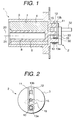
- Fig. 1 is a sectional view showing a key cylinder automatic returning device for a cylinder lock device according to a first embodiment of the present invention;
- Fig. 2 is a rear view of the device of Fig. 1;
- Fig. 3 is a sectional view showing a key cylinder automatic returning device for a cylinder lock device according to a second embodiment of the invention;
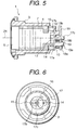
- Fig. 4 is a sectional view showing a key cylinder automatic returning device for a cylinder lock device according to a third embodiment of the invention;
- Fig. 5 is a sectional view taken along line C in Fig. 4;
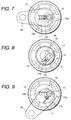
- Fig. 6 is a sectional view taken along line A in Fig. 4;
- Fig. 7 is a sectional view taken along line B in Fig. 4;
- Fig. 8 is a sectional view taken along line A in Fig. 4 showing a state in which a key cylinder is rotated by the proper key;
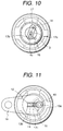
- Fig. 9 is a sectional view taken along line B in Fig. 4 showing a state in which the key cylinder is rotated by the proper key;
- Fig. 10 is a sectional view taken along line A in Fig. 4 showing a state in which the key cylinder is rotated by an improper key; and
- Fig. 11 is a sectional view taken along line B in Fig. 4 showing a state in which the key cylinder is rotated by an improper key.
- Key cylinder automatic returning devices for a cylinder lock device according to embodiments of the present invention will be hereinafter described with reference to Figs. 1-11.
- As shown in Fig. 1, a
cylinder lock device 1 according to a first embodiment of the invention has acase 3 provided with afirst housing 7, asleeve 4 that is rotatably incorporated in thefirst housing 7 of thecase 3 and provided with asecond housing 8, and akey cylinder 5 rotatably installed in thesecond housing 8 of thesleeve 4. As illustrated in Fig. 2, a circular-arc groove 16 is formed in thecase 3. Tumblers (not shown) such as disk tumblers or pin tumblers are slidably arranged in thekey cylinder 5 by the known method. The tumblers are engaged with an engaging portion that is, for instance, tumbler grooves or pin holes of thesleeve 4 so as to be separable therefrom. - A key cylinder automatic returning
device 2 of thiscylinder lock device 1 is provided with acylinder shaft 15 that projects from thekey cylinder 5 along thecentral axis 20 of thesleeve 4 passing through the circular-arc groove 16 of thecase 3, and a pair ofcase shafts case 3. Aspring 10 is coiled on thecase shaft 13a. Thecylinder shaft 15 is so disposed as to be closer to thecase shaft 13a than thecase shaft 13b. Thecylinder shaft 15 and thecase shaft 13b are placed between bothlegs spring 10. Alever 31 that is rotatably supported by a through-hole 30 is fixed to the case shaft (pivot) 13a with a clip or the like (not shown). Thelever 31 has a through-hole 33 into which thecylinder shaft 15 is inserted and anarm 32 for driving a lock device (not shown). - With the aforementioned structure, when the proper key is inserted into the
key cylinder 5 and turned, the tumblers are disengaged from the engaging portion of thesleeve 4 and thekey cylinder 5 is rotated relative to thesleeve 4. As a result, thecylinder shaft 15 makes an arcuate movement around thecentral axis 21 of thekey cylinder 5 while being confined by the circular-arc groove 16 formed in thecase 3. The arcuate movement of thecylinder shaft 15 causes thelever 31 to be rotated around the case shaft (pivot) 13a, so that thearm 32 locks or unlocks the lock device. When thecylinder shaft 15 is rotated to the locked position or the unlocked position, thespring 10 imparts returning force to thecylinder shaft 15 at a location between the fixedcase shafts key cylinder 5 can be automatically returned from the rotated position to the original position by resilient force of thespring 10. - When an improper key is inserted into the
key cylinder 5 and turned, thekey cylinder 5 and thesleeve 4 are rotated together around thecentral axis 20 of thesleeve 4 and thecylinder shaft 15 does not elastically deform thespring 10. That is, thecylinder shaft 15 is rotated on thecentral axis 20 of thesleeve 4 within the circular-arc groove 16 of thecase 3 and between bothlegs spring 10, without deforming thespring 10. - Fig. 3 is a sectional view illustrating a second embodiment of the invention. In Figs. 3-11, the parts corresponding to those in Figs. 1 and 2 are given the same reference symbols and descriptions therefor will be omitted.
- A
cylinder lock device 1 shown in Fig. 3 is provided with a sleevecentral shaft 14a that projects from thesleeve 4 and extends along the center line of thesleeve 4, a sleeveeccentric shaft 14b that projects from thesleeve 4 at a position deviated from the center of thesleeve 4, acylinder shaft 15 that projects from thekey cylinder 5 at a position deviated from the sleeveeccentric shaft 14b and is closer to the sleevecentral shaft 14a than the sleeveeccentric shaft 14b, and aspring 10 coiled on the sleevecentral shaft 14a. A through-hole 33 for thelever 31 is arranged on thecylinder shaft 15. Thecylinder shaft 15 is located closer to the sleevecentral shaft 14a than the sleeveeccentric shaft 14b, and thecylinder shaft 15 and the sleeveeccentric shaft 14b are placed between bothlegs spring 10. - When the proper key is inserted into the
key cylinder 5 and turned, the tumblers are disengaged from the engaging portion of thesleeve 4 and thekey cylinder 5 can be rotated relative to thesleeve 4. When thekey cylinder 5 is rotated with respect to thesleeve 4, thecylinder shaft 15 makes an arcuate movement around thecentral axis 21 of thekey cylinder 5, and thearm 32 is rotated around thecentral axis 21 to lock or unlock a lock device. When making an arcuate movement, thecylinder shaft 15 receives a returning force from thespring 10. When the rotational force is removed from the key at the locked position or the unlocked position, thekey cylinder 5 can be automatically returned from the rotated position to the original position by resilience of thespring 10. - When the
key cylinder 5 is rotated by an improper key and thekey cylinder 5, thesleeve 4 are thereby rotated together around thecentral axis 20 of thesleeve 4 and thecylinder shaft 15 does not elastically deform thespring 10. Thus, thecylinder shaft 15 is rotated together with thespring 10 around thecentral axis 20 of thesleeve 4 without deforming thespring 10. When anarm 32 is rotated around thecentral axis 21, it comes into contact with the lock device. However, when thearm 32 is rotated around thecentral axis 20, it does not contact with and therefore does not actuate the lock device. - Figs. 4-11 show a third embodiment of the invention. In a
cylinder lock 1, asleeve 4 is provided with an engagingportion 9, and atumbler 6 is slidably provided in each of a plurality ofslits 5a of akey cylinder 5. When thetumblers 6 project from thekey cylinder 5, they can contact with the engagingportion 9 of thesleeve 4. Aslot 40 is formed in thesleeve 4 in the radial direction, and aspring 42 and aball 41 are placed in theslot 40. Theball 41 is pushed outward in the radial direction by resilience of thespring 42 against a V-shapedgroove 43 that is formed in acase 3. When thesleeve 4 and thekey cylinder 5 are rotated together by an improper key, thesleeve 4 can be returned to the regular position by theball 41 being engagement with thegroove 43. Thegroove 43 serves as a water path to remove water that has been introduced into thecylinder lock 1. - The
cylinder lock 1 of this embodiment is provided with asleeve shaft 14 eccentric to thesleeve 4 and projecting therefrom axially and acylinder shaft 15 deviated from acentral axis 21 of the key cylinder and axially projecting from the key cylinder 5 (see Fig. 5). Thesleeve shaft 14 is inserted into a through-hole 17a of aninside lever 17, and theinside lever 17 is rotatably mounted on thesleeve shaft 14. Theinside lever 17 is provided with alever shaft 17c and acut 17b that fits with thecylinder shaft 15. Thelever shaft 17c projects axially along thecentral axis 21 of thekey cylinder 5 passing through a circular-arc groove 16 formed in thecase 3. Thecase 3 is provided with a pair ofcase shafts central axis 21 of thekey cylinder 5 and extend axially. Thecase shafts 13a fits into a through-hole 18a of anoutside lever 18 to rotatably support theoutside lever 18. Theoutside lever 18 is provided with areceptacle hole 18b that fits with thelever shaft 17c, and abracket 19 attached to thecase shaft 13a prevents theoutside lever 18 from falling off. Aspring 10 is coiled on thecase shaft 13a. Thelever shaft 17c is located closer to thecase shaft 13a than thecase shaft 13b. Thelever shaft 17c and thecase shaft 13b are placed between bothlegs spring 10. - With the above structure, when no key is inserted into the
key cylinder 5, thekey cylinder 5,sleeve 4, insidelever 17, and outsidelever 18 are in the neutral positions as shown in Figs. 4-7. When thekey cylinder 5 is rotated by the proper key being inserted in thekey cylinder 5, thetumblers 6 are disengaged from the engagingportion 9 of thesleeve 4 and thekey cylinder 5 can be rotated relative to thesleeve 4. As a result, thecylinder shaft 15 is rotated around thecentral axis 21 of thekey cylinder 5, and thelever shaft 17c of theinside lever 17 makes an arcuate movement in the circular-arc groove 16 of thecase 3 around thesleeve shaft 14. Therefore, theinside lever 17 is rotated from the neutral position (see Fig. 6) to the operating position (locked position or unlocked position; see Fig. 8) around thesleeve shaft 14, and theoutside lever 18 is rotated from the neutral position (see Fig. 7) to the operating position (locked position or unlocked position; see Fig. 9) around thecase shaft 13a. Thus, a lock device can be locked or unlocked by the rotation of thecylinder shaft 15 through the action of theinside lever 17 and theoutside lever 18. - When the
lever shaft 17c is rotated in the circular-arc groove 16, bothlegs spring 19 impart returning force to thelever shaft 17c. When the rotational force is removed from the key located at the operating position, thekey cylinder 15 can be automatically returned from the rotated position to the original position by resilience of thespring 10 through the action of theinside lever 17. - When the
key cylinder 5 and thesleeve 4 are rotated together by an improper key being inserted in thekey cylinder 5, thelever shaft 17c is rotated on thecentral axis 21 of thekey cylinder 5 and therefore does not make an arcuate movement. As a result, theinside lever 17 rotates but does not make an arcuate movement (see Fig. 10), and theoutside lever 18 is left in the neutral state (see Fig. 11). Therefore, thelever shaft 17c is rotated on thecylinder axis 21 in the circular-arc groove 16 of thecase 3 and between both legs of thespring 10, without deforming thespring 10. - As described above, according to the invention, the key cylinder automatic returning device causes the key cylinder to automatically return to the original position when it is rotated by the proper key. Therefore, the key can be pulled out from the key cylinder in the rotated position; that is, a free-turn lock device can be operated more easily.
Claims (3)
- A key cylinder automatic returning device for a cylinder lock device which comprises a case having a first housing, a sleeve rotatably incorporated in the first housing of the case and having a second housing and an engaging portion, a key cylinder rotatably incorporated in the second housing of the sleeve, and tumblers slidably arranged in the key cylinder and capable of engaging with the engaging portion of the sleeve, and in which the key cylinder is rotated with respect to the sleeve when a proper key is inserted into the key cylinder and turned, and the key cylinder and the sleeve are rotated together when an improper key is inserted into the key cylinder and turned, said key cylinder automatic returning device comprising:
first and second case shafts projecting from the case;
a cylinder shaft projecting from the key cylinder along a center line of the sleeve, and located between the first and second case shafts; and
a spring coiled on the first case shaft, and having two legs between which the cylinder shaft and the second case shaft are placed,
wherein when the key cylinder is rotated with respect to the sleeve by the proper key being inserted in the key cylinder, the spring imparts returning force to the cylinder shaft that is making an arcuate movement in a circular-arc groove formed in the case; and
wherein when the key cylinder and the sleeve are rotated together by an improper key being inserted in the key cylinder, the cylinder shaft is rotated on the center line of the sleeve in the circular-arc groove of the case and between the two legs of the spring without deforming the spring. - A key cylinder automatic returning device for a cylinder lock device which comprises a case having a first housing, a sleeve rotatably incorporated in the first housing of the case and having a second housing and an engaging portion, a key cylinder rotatably incorporated in the second housing of the sleeve, and tumblers slidably arranged in the key cylinder and capable of engaging with the engaging portion of the sleeve, and in which the key cylinder is rotated with respect to the sleeve when a proper key is inserted into the key cylinder and turned, and the key cylinder and the sleeve are rotated together when an improper key is inserted into the key cylinder and turned, said key cylinder automatic returning device comprising:
a sleeve central shaft projecting from the sleeve along a center line of the sleeve;
a sleeve eccentric shaft deviated from the center line of the sleeve and projecting therefrom;
a cylinder shaft deviated from the sleeve central shaft, projecting from the key cylinder, and located between the sleeve central shaft and the sleeve eccentric shaft; and
a spring coiled on the sleeve central shaft, and having two legs between which the cylinder shaft and the sleeve eccentric shaft are placed,
wherein when the key cylinder is rotated with respect to the sleeve by the proper key being inserted in the key cylinder, the spring imparts returning force to the cylinder shaft that is making an arcuate movement; and
wherein when the key cylinder and the sleeve are rotated together by an improper key being inserted in the key cylinder, the cylinder shaft is rotated around the center line of the sleeve between the two legs of the spring without deforming the spring. - A key cylinder automatic returning device for a cylinder lock device which comprises a case having a first housing, a sleeve rotatably incorporated in the first housing of the case and having a second housing and an engaging portion, a key cylinder rotatably incorporated in the second housing of the sleeve, and tumblers slidably arranged in the key cylinder and capable of engaging with the engaging portion of the sleeve, and in which the key cylinder is rotated with respect to the sleeve when a proper key is inserted into the key cylinder and turned, and the key cylinder and the sleeve are rotated together when an improper key is inserted into the key cylinder and turned, said key cylinder automatic returning device comprising:
a sleeve shaft eccentric to the sleeve and axially projecting therefrom;
a cylinder shaft deviated from a center line of the key cylinder and axially projecting from the key cylinder;
first and second case shafts eccentric to the case and axially projecting from the case;
an inside lever rotatably attached to the sleeve shaft, and having a cut that fits with the cylinder shaft, and a lever shaft axially projecting along the center line of the key cylinder passing through a circular-arc groove formed in the case and located between the first and second case shafts;
an outside lever rotatably attached to the first case shaft, and having a receptacle hole that fits with the lever shaft; and
a spring coiled on the first case shaft, and having two legs between which the lever shaft and the second case shaft are placed,
wherein when the key cylinder is rotated with respect to the sleeve by the proper key being inserted into the key cylinder, the inside lever is rotated around the sleeve shaft, so that the spring imparts returning force to the lever shaft that is making an arcuate movement in the circular-arc groove; and
and wherein when the key cylinder and the sleeve are rotated together by an improper key being inserted in the key cylinder, the lever shaft is rotated on the center line of the key cylinder in the circular-arc groove of the case and between the two legs of the spring without deforming the spring.
Applications Claiming Priority (2)
| Application Number | Priority Date | Filing Date | Title |
|---|---|---|---|
| JP92737/94 | 1994-04-28 | ||
| JP09273794A JP3298737B2 (en) | 1994-04-28 | 1994-04-28 | Key cylinder automatic return device for cylinder lock device |
Publications (2)
| Publication Number | Publication Date |
|---|---|
| EP0679782A1 true EP0679782A1 (en) | 1995-11-02 |
| EP0679782B1 EP0679782B1 (en) | 1998-11-04 |
Family
ID=14062737
Family Applications (1)
| Application Number | Title | Priority Date | Filing Date |
|---|---|---|---|
| EP95106456A Expired - Lifetime EP0679782B1 (en) | 1994-04-28 | 1995-04-28 | Key cylinder automatic returning device for cylinder lock device |
Country Status (6)
| Country | Link |
|---|---|
| US (1) | US5630331A (en) |
| EP (1) | EP0679782B1 (en) |
| JP (1) | JP3298737B2 (en) |
| DE (1) | DE69505725T2 (en) |
| ES (1) | ES2124932T3 (en) |
| HK (1) | HK1012037A1 (en) |
Cited By (1)
| Publication number | Priority date | Publication date | Assignee | Title |
|---|---|---|---|---|
| CN101258295B (en) * | 2005-09-17 | 2012-03-21 | 秦才东 | Anti-twisted anti-prizing type lock |
Families Citing this family (8)
| Publication number | Priority date | Publication date | Assignee | Title |
|---|---|---|---|---|
| DE10243615B4 (en) * | 2002-09-19 | 2004-09-23 | Meister, Klaus, Dr. | Electronic cylinder system for panic locks |
| DE10316522B3 (en) * | 2003-04-10 | 2004-07-08 | Seccor High Security Gmbh | Automatic resetting system for electronic locking system used with panic lock for access door has eccentric core supported by spring-loaded ball bearing defining rest position of locking cam axis |
| DE102006020614B4 (en) * | 2005-04-29 | 2017-02-02 | Mehmet Sancak | Lock with automatic reset of the lock |
| JP4690236B2 (en) * | 2006-04-07 | 2011-06-01 | 株式会社東海理化電機製作所 | Key cylinder |
| DE102008029686B4 (en) | 2008-01-19 | 2016-07-28 | Dom Sicherheitstechnik Gmbh & Co. Kg | Lock cylinder with automatic return of the closing member |
| DE102008056627C5 (en) * | 2008-11-10 | 2012-08-02 | Wilka Schließtechnik GmbH | Profile cylinder lock with one-piece radial housing attachment and with automatic reset device for a cam or follower body |
| JP5292386B2 (en) * | 2010-12-22 | 2013-09-18 | 株式会社ホンダロック | Central unlocking device |
| US8978428B2 (en) * | 2011-09-08 | 2015-03-17 | Medeco Security Locks, Inc. | Apparatus for automatically returning a lock to a desired orientation |
Citations (2)
| Publication number | Priority date | Publication date | Assignee | Title |
|---|---|---|---|---|
| FR2620755A2 (en) * | 1984-01-31 | 1989-03-24 | Dupart Jean | Lock with an attached safety unit arranged to prevent its fraudulent opening |
| US4936895A (en) * | 1989-01-30 | 1990-06-26 | Valeo Neiman | Releasable lock with a rotable stator |
Family Cites Families (12)
| Publication number | Priority date | Publication date | Assignee | Title |
|---|---|---|---|---|
| FR498510A (en) * | 1918-03-20 | 1920-01-14 | Francis Trowbridge Snow | Locking system for automobile gears |
| US1876803A (en) * | 1929-12-30 | 1932-09-13 | Mehren Lock Co Inc | Bolt operating mechanism for locks |
| US3310642A (en) * | 1964-04-30 | 1967-03-21 | Gen Motors Corp | Tail gate electric window and gate switch |
| US4655062A (en) * | 1983-01-10 | 1987-04-07 | Lazar Kaufman | System of interconnected lock-cylinders |
| US4633689A (en) * | 1984-09-04 | 1987-01-06 | The Eastern Company | Anti-static switch lock with momentary position |
| US4634822A (en) * | 1985-11-15 | 1987-01-06 | Fort Lock Corporation | Multiple operation switch lock |
| FR2631067B1 (en) * | 1988-05-04 | 1991-02-08 | Neiman Sa | RELEASABLE ROTOR LOCK |
| US5285667A (en) * | 1990-11-30 | 1994-02-15 | Alpha Corporation | Cylinder lock |
| US5265453A (en) * | 1990-11-30 | 1993-11-30 | Alpha Corporation | Cylinder lock |
| DE4122414C1 (en) * | 1991-07-06 | 1992-12-03 | Huelsbeck & Fuerst | Locking cylinder |
| US5186030A (en) * | 1991-11-25 | 1993-02-16 | Taiwan Fu Hsing Industry Co., Ltd. | Locking device for an auxiliary lock |
| US5428978A (en) * | 1994-03-29 | 1995-07-04 | Alpha Corporation | Cylinder lock device resistible against unauthorized unlocking |
-
1994
- 1994-04-28 JP JP09273794A patent/JP3298737B2/en not_active Expired - Fee Related
-
1995
- 1995-04-28 ES ES95106456T patent/ES2124932T3/en not_active Expired - Lifetime
- 1995-04-28 DE DE69505725T patent/DE69505725T2/en not_active Expired - Fee Related
- 1995-04-28 US US08/430,610 patent/US5630331A/en not_active Expired - Fee Related
- 1995-04-28 EP EP95106456A patent/EP0679782B1/en not_active Expired - Lifetime
-
1998
- 1998-12-10 HK HK98113063A patent/HK1012037A1/en not_active IP Right Cessation
Patent Citations (2)
| Publication number | Priority date | Publication date | Assignee | Title |
|---|---|---|---|---|
| FR2620755A2 (en) * | 1984-01-31 | 1989-03-24 | Dupart Jean | Lock with an attached safety unit arranged to prevent its fraudulent opening |
| US4936895A (en) * | 1989-01-30 | 1990-06-26 | Valeo Neiman | Releasable lock with a rotable stator |
Cited By (1)
| Publication number | Priority date | Publication date | Assignee | Title |
|---|---|---|---|---|
| CN101258295B (en) * | 2005-09-17 | 2012-03-21 | 秦才东 | Anti-twisted anti-prizing type lock |
Also Published As
| Publication number | Publication date |
|---|---|
| JP3298737B2 (en) | 2002-07-08 |
| DE69505725T2 (en) | 1999-04-08 |
| EP0679782B1 (en) | 1998-11-04 |
| JPH07293064A (en) | 1995-11-07 |
| HK1012037A1 (en) | 1999-07-23 |
| ES2124932T3 (en) | 1999-02-16 |
| DE69505725D1 (en) | 1998-12-10 |
| US5630331A (en) | 1997-05-20 |
Similar Documents
| Publication | Publication Date | Title |
|---|---|---|
| EP0488786B1 (en) | Cylinder lock | |
| EP0675248B1 (en) | Cylinder lock device resistible against unauthorized unlocking | |
| EP0659962B1 (en) | Cylinder lock resistible against breaking | |
| US4394821A (en) | Door lock mechanism | |
| US6058751A (en) | Free-wheeling lock | |
| US5285667A (en) | Cylinder lock | |
| JP2000203387A (en) | Theft preventing device attached on steering column of automobile | |
| EP0679782B1 (en) | Key cylinder automatic returning device for cylinder lock device | |
| EP0650874B1 (en) | Steering lock device | |
| GB2339448A (en) | Cylinder lock mechanism | |
| JP3017276B2 (en) | Cylinder lock | |
| JPH04315677A (en) | Cylinder lock | |
| US5488847A (en) | Pick proof lock | |
| JP3441033B2 (en) | Steering lock device | |
| US5709115A (en) | Sidebar ignition lock | |
| JPH0559849A (en) | Cylinder lock | |
| FI90579C (en) | Cylinder lock key combination and key for it | |
| JP3470844B2 (en) | Steering lock device | |
| JPH07189533A (en) | Cylinder lock device | |
| JPH0332215Y2 (en) | ||
| JP3031436B2 (en) | Steering lock device | |
| KR850001403Y1 (en) | Locking device of steering in vehicle | |
| JPH08120982A (en) | Cylinder lock | |
| JP4328665B2 (en) | Locking device | |
| JP2001500204A (en) | Lever lock device |
Legal Events
| Date | Code | Title | Description |
|---|---|---|---|
| PUAI | Public reference made under article 153(3) epc to a published international application that has entered the european phase |
Free format text: ORIGINAL CODE: 0009012 |
|
| AK | Designated contracting states |
Kind code of ref document: A1 Designated state(s): DE ES FR GB |
|
| 17P | Request for examination filed |
Effective date: 19960227 |
|
| 17Q | First examination report despatched |
Effective date: 19970612 |
|
| GRAG | Despatch of communication of intention to grant |
Free format text: ORIGINAL CODE: EPIDOS AGRA |
|
| RAP1 | Party data changed (applicant data changed or rights of an application transferred) |
Owner name: ALPHA CORPORATION |
|
| GRAG | Despatch of communication of intention to grant |
Free format text: ORIGINAL CODE: EPIDOS AGRA |
|
| GRAH | Despatch of communication of intention to grant a patent |
Free format text: ORIGINAL CODE: EPIDOS IGRA |
|
| GRAH | Despatch of communication of intention to grant a patent |
Free format text: ORIGINAL CODE: EPIDOS IGRA |
|
| GRAA | (expected) grant |
Free format text: ORIGINAL CODE: 0009210 |
|
| AK | Designated contracting states |
Kind code of ref document: B1 Designated state(s): DE ES FR GB |
|
| REF | Corresponds to: |
Ref document number: 69505725 Country of ref document: DE Date of ref document: 19981210 |
|
| REG | Reference to a national code |
Ref country code: ES Ref legal event code: FG2A Ref document number: 2124932 Country of ref document: ES Kind code of ref document: T3 |
|
| ET | Fr: translation filed | ||
| PLBE | No opposition filed within time limit |
Free format text: ORIGINAL CODE: 0009261 |
|
| STAA | Information on the status of an ep patent application or granted ep patent |
Free format text: STATUS: NO OPPOSITION FILED WITHIN TIME LIMIT |
|
| 26N | No opposition filed | ||
| REG | Reference to a national code |
Ref country code: GB Ref legal event code: IF02 |
|
| PGFP | Annual fee paid to national office [announced via postgrant information from national office to epo] |
Ref country code: FR Payment date: 20050408 Year of fee payment: 11 |
|
| PGFP | Annual fee paid to national office [announced via postgrant information from national office to epo] |
Ref country code: DE Payment date: 20050421 Year of fee payment: 11 |
|
| PGFP | Annual fee paid to national office [announced via postgrant information from national office to epo] |
Ref country code: GB Payment date: 20050427 Year of fee payment: 11 |
|
| PGFP | Annual fee paid to national office [announced via postgrant information from national office to epo] |
Ref country code: ES Payment date: 20050527 Year of fee payment: 11 |
|
| PG25 | Lapsed in a contracting state [announced via postgrant information from national office to epo] |
Ref country code: GB Free format text: LAPSE BECAUSE OF NON-PAYMENT OF DUE FEES Effective date: 20060428 |
|
| PG25 | Lapsed in a contracting state [announced via postgrant information from national office to epo] |
Ref country code: ES Free format text: LAPSE BECAUSE OF NON-PAYMENT OF DUE FEES Effective date: 20060429 |
|
| PG25 | Lapsed in a contracting state [announced via postgrant information from national office to epo] |
Ref country code: DE Free format text: LAPSE BECAUSE OF NON-PAYMENT OF DUE FEES Effective date: 20061101 |
|
| GBPC | Gb: european patent ceased through non-payment of renewal fee |
Effective date: 20060428 |
|
| REG | Reference to a national code |
Ref country code: FR Ref legal event code: ST Effective date: 20061230 |
|
| REG | Reference to a national code |
Ref country code: ES Ref legal event code: FD2A Effective date: 20060429 |
|
| PG25 | Lapsed in a contracting state [announced via postgrant information from national office to epo] |
Ref country code: FR Free format text: LAPSE BECAUSE OF NON-PAYMENT OF DUE FEES Effective date: 20060502 |