EP0675248B1 - Cylinder lock device resistible against unauthorized unlocking - Google Patents
Cylinder lock device resistible against unauthorized unlocking Download PDFInfo
- Publication number
- EP0675248B1 EP0675248B1 EP19940302310 EP94302310A EP0675248B1 EP 0675248 B1 EP0675248 B1 EP 0675248B1 EP 19940302310 EP19940302310 EP 19940302310 EP 94302310 A EP94302310 A EP 94302310A EP 0675248 B1 EP0675248 B1 EP 0675248B1
- Authority
- EP
- European Patent Office
- Prior art keywords
- key cylinder
- lever
- cylinder
- locked position
- lock device
- Prior art date
- Legal status (The legal status is an assumption and is not a legal conclusion. Google has not performed a legal analysis and makes no representation as to the accuracy of the status listed.)
- Expired - Lifetime
Links
Images


Classifications
-
- E—FIXED CONSTRUCTIONS
- E05—LOCKS; KEYS; WINDOW OR DOOR FITTINGS; SAFES
- E05B—LOCKS; ACCESSORIES THEREFOR; HANDCUFFS
- E05B17/00—Accessories in connection with locks
- E05B17/04—Devices for coupling the turning cylinder of a single or a double cylinder lock with the bolt operating member
-
- E—FIXED CONSTRUCTIONS
- E05—LOCKS; KEYS; WINDOW OR DOOR FITTINGS; SAFES
- E05B—LOCKS; ACCESSORIES THEREFOR; HANDCUFFS
- E05B47/00—Operating or controlling locks or other fastening devices by electric or magnetic means
- E05B2047/0048—Circuits, feeding, monitoring
- E05B2047/0067—Monitoring
- E05B2047/0069—Monitoring bolt position
-
- Y—GENERAL TAGGING OF NEW TECHNOLOGICAL DEVELOPMENTS; GENERAL TAGGING OF CROSS-SECTIONAL TECHNOLOGIES SPANNING OVER SEVERAL SECTIONS OF THE IPC; TECHNICAL SUBJECTS COVERED BY FORMER USPC CROSS-REFERENCE ART COLLECTIONS [XRACs] AND DIGESTS
- Y10—TECHNICAL SUBJECTS COVERED BY FORMER USPC
- Y10T—TECHNICAL SUBJECTS COVERED BY FORMER US CLASSIFICATION
- Y10T70/00—Locks
- Y10T70/70—Operating mechanism
- Y10T70/7051—Using a powered device [e.g., motor]
- Y10T70/7057—Permanent magnet
-
- Y—GENERAL TAGGING OF NEW TECHNOLOGICAL DEVELOPMENTS; GENERAL TAGGING OF CROSS-SECTIONAL TECHNOLOGIES SPANNING OVER SEVERAL SECTIONS OF THE IPC; TECHNICAL SUBJECTS COVERED BY FORMER USPC CROSS-REFERENCE ART COLLECTIONS [XRACs] AND DIGESTS
- Y10—TECHNICAL SUBJECTS COVERED BY FORMER USPC
- Y10T—TECHNICAL SUBJECTS COVERED BY FORMER US CLASSIFICATION
- Y10T70/00—Locks
- Y10T70/70—Operating mechanism
- Y10T70/7441—Key
- Y10T70/7486—Single key
- Y10T70/7508—Tumbler type
- Y10T70/7559—Cylinder type
- Y10T70/7638—Cylinder and plug assembly
-
- Y—GENERAL TAGGING OF NEW TECHNOLOGICAL DEVELOPMENTS; GENERAL TAGGING OF CROSS-SECTIONAL TECHNOLOGIES SPANNING OVER SEVERAL SECTIONS OF THE IPC; TECHNICAL SUBJECTS COVERED BY FORMER USPC CROSS-REFERENCE ART COLLECTIONS [XRACs] AND DIGESTS
- Y10—TECHNICAL SUBJECTS COVERED BY FORMER USPC
- Y10T—TECHNICAL SUBJECTS COVERED BY FORMER US CLASSIFICATION
- Y10T70/00—Locks
- Y10T70/70—Operating mechanism
- Y10T70/7441—Key
- Y10T70/7486—Single key
- Y10T70/7508—Tumbler type
- Y10T70/7559—Cylinder type
- Y10T70/7667—Operating elements, parts and adjuncts
- Y10T70/7706—Operating connections
-
- Y—GENERAL TAGGING OF NEW TECHNOLOGICAL DEVELOPMENTS; GENERAL TAGGING OF CROSS-SECTIONAL TECHNOLOGIES SPANNING OVER SEVERAL SECTIONS OF THE IPC; TECHNICAL SUBJECTS COVERED BY FORMER USPC CROSS-REFERENCE ART COLLECTIONS [XRACs] AND DIGESTS
- Y10—TECHNICAL SUBJECTS COVERED BY FORMER USPC
- Y10T—TECHNICAL SUBJECTS COVERED BY FORMER US CLASSIFICATION
- Y10T70/00—Locks
- Y10T70/70—Operating mechanism
- Y10T70/7441—Key
- Y10T70/7751—With ball or roller
Definitions
- the present invention relates, in general, to a lock and more particularly, to a cylinder lock device firmly resistible against unauthorized unlocking by tampering.
- JP-A-2-261178 discloses a cylinder lock used for vehicle doors.
- the cylinder lock of this kind comprises a casing provided with a hole; a key cylinder rotatably disposed within the hole of the casing; a first lever attached with angular clearance to the key cylinder and drivingly connected to a locking device equipped on a door; a spring for resiliently urging the first lever when rotated; a stopper provided on the casing for preventing rotation of the first lever over a predetermined rotated angle; and a second lever attached to the key cylinder.
- DE-A-3513287 which represents the closest prior art, describes a cylinder lock device which includes a housing, a key cylinder rotatably mounted in the housing and a drive member having a tongue portion formed with a slit to receive a ball.
- a concavity is formed in an outer surface of the housing.
- the drive member is rotated together with the key cylinder and a rotator 23 between unlocked and locked positions.
- the key cylinder is rotated to a dead-locked position from the locked position, the drive member is kept in the locked position because the ball is retained in the concavity.
- the present invention proposes an alternative solution.
- New cylinder locks are recently required which are fully resistible against unauthorized unlocking by tampering locking devices.
- locking devices may inconveniently be unlocked by tampering, with a specific tool, a lock knob provided in a vehicle door for manual operation of the locking device although the cylinder lock is kept in the locked condition.
- DE-A-3513287 discloses one possible solution for overcoming this problem.
- an object of the present invention is to provide a novel cylinder lock device firmly resistible, against unauthorized attempt to unlock a locking device by tampering, by forcibly maintaining the locking device in the locked condition to bar unlocking of the locking device in an alternative way compared to the state of the art.
- Another object of the present invention is to provide a cylinder lock device which can protect a locking device from unauthorized attempt to unlock by tampering a relating part of a locking device.
- Still another object of the present invention is to provide a cylinder lock device which perfectly inhibits any operation of a locking device when the cylinder lock device is in the dead-locked position.
- a cylinder lock device comprising a casing which has a plurality of grooves formed in said casing; a key cylinder rotatably disposed within said casing, said key cylinder having slots formed therein; and tumblers slidably disposed in said slots of said key cylinder for engagement with or disengagement from said grooves of said casing;
- the grooves are formed in the casing at angular intervals of 90 degrees.
- the blocking member comprises a roller or ball. A key is inserted into or pulled from the key cylinder in the neutral or unlocked position or in the dead-locked position of the key cylinder.
- the lever rotates with the blocking member retained in the notched formed between a pair of arcuate lugs of the lever when the key cylinder is rotated by a key until the blocking member is received within the concavity of the casing.
- a bracket Secured to the key cylinder for rotation between the unlocked and dead-locked positions is a bracket which is provided with a magnet detected by a magnetic sensor to indicate the position of the key cylinder.
- the lever When the key cylinder is rotated from a neutral or unlocked position to a locked position, the lever is rotated together with the key cylinder. Simultaneously, the blocking member is rotated from the neutral or unlocked position to the locked position in the condition disposed within the notch of the lever and on the chamfer of the key cylinder. When the key cylinder is further rotated from the locked position to the dead-locked position, the blocking member moves away from the chamfer of the key cylinder and into the concavity of the casing for engagement.
- the key cylinder After the key is pulled out from the key cylinder in the dead locked position, the key cylinder is firmly kept in the dead-locked position so that the lever and the locking device can be forcibly maintained in the locked position, thereby preventing unauthorized unlocking of the locking device although an external force is applied to any relating part connected with the locking device.
- the cylinder lock device 10 comprises a casing 11 formed with a hole 11a and four longitudinal grooves 12, a key cylinder 13 rotatably disposed within the hole 11a of the casing 11 and tumblers 14 slidably disposed within slots 13a formed in the key cylinder 13.
- the grooves 12 are formed at angular intervals of 90 degrees on an inner wall 11c of the hole 11a of the casing 11 such that the tumblers 14 are moved between their retracted position within the slots 13a for rotation of the key cylinder 13 and extended position projecting from the slots 13a for engagement with the grooves 12, similarly to prior art cylinder locks.
- a key may be inserted into and pulled out from the key cylinder 13 when the tumblers 14 move into and away from the grooves 12.
- a lever 15 has a central hole 24 to receive a central protrusion 25 of the key cylinder 13 so that a cylindrical portion 25a of the central protrusion 25 is in contact with the hole 24.
- the lever 15 has also an arm 23 formed with a hole 22 to receive a rod (not shown) drivingly connected with a door locking device of a vehicle door; a pair of arcuate lugs 20 rotatably disposed between the casing 11 and the key cylinder 13 (Fig. 9); and a notch 16 axially extending between these arcuate lugs 20.
- a blocking member 17 of for example a roller or ball is disposed in the notch 16 and on a U-shaped chamfer 19 formed in the key cylinder 13.
- a bracket 30 is attached to the end portion of the key cylinder 13 adjacent to and outward of the lever 15.
- the bracket 30 has an opening 31 of substantially oval or non-circular shape in section to receive a notched portion 25b of the central protrusion 25 of the key cylinder 13 for integral rotation of the bracket 30 and the key cylinder 13.
- a magnet 33 is secured in a recess 32 formed at the end portion of the bracket 30.
- an E-shaped ring 34 is attached to an annular recess 25c of the center protrusion 25 outward of the bracket 30 to prevent detachment of the lever 15 and the bracket 30 from the center protrusion 25.
- a coiled spring 40 wound around the casing 11 is a coiled spring 40 having two ends 40a and 40b between which L-shaped lugs 26 and 41 of the lever 15 and casing 11 are positioned in a radially overlapped condition so that the coiled spring 40 applies an elastic returning force to the key cylinder 13 when the key cylinder 13 is rotated from the neutral position of Fig 9 in either direction.
- the key cylinder 13 has an integrally formed protrusion 13b which is brought into contact with a stopper or lug 42 formed on the inner wall 11c of the hole 11a of the casing 11 to bar further rotation of the key cylinder 13 when the key cylinder 13 is rotated to the dead-locked position. Also, when the lever 15 is fully rotated together with the key cylinder 13, either of the arcuate lugs 20 of the lever 15 is brought into contact with the stopper 42 to restrict further rotation of the lever 15.
- a spring 28 and a ball 29 are disposed in a radial hole 27 formed in the key cylinder 13 as shown in Fig. 7 to resiliently urge the ball 29 by the spring 28 against the inner wall 11c of the casing 11 so that the ball 29 is engaged with a V-shaped recess 11b formed on the inner wall 11c of the casing 11 for click stop when the key cylinder 13 is rotated to the dead-locked position as shown in Figs. 8, 21 and 22.
- An axial concavity 18 is formed on the inner wall 11c of the casing 11 to receive the blocking member 17 when the lever 15 is in the locked position.
- the key cylinder 13, lever 15, blocking member 17 and bracket 30 are in the neutral position of Figs. 9 and 10 wherein the blocking member 17 is received within the notch 16 of the lever 15 and on the U-shaped chamfer 19 of the key cylinder 13.
- the key cylinder 13 is rotated in the same direction together with the lever 15, blocking member 17 and bracket 30 to the unlocked position as shown in Figs. 11 and 12.
- the blocking member 17 serves to connect the key cylinder 13 and the lever 15 for their integral rotation.
- one of the arcuate lugs 20 is brought into contact with the lug 42 of the casing 11 to stop rotation of the key cylinder 13 and lever 15, and thereby the arm 23 makes a locking device in the unlocking condition via a rod connected with the hole 22.
- the lever 15 is rotated to the unlocked position so that the magnet 33 is detected by a ferrous sensor (not shown) which produces an electric signal representing that the bracket 30 is in the unlocked position.
- the coiled spring 40 produces a returning force of the lever 15 when rotated to the unlocked position because the L-shaped lug 26 of the lever 15 is in contact with one end 40a of the expanded spring 40. Accordingly, when the key cylinder 13 is rotated to the unlocked position and a manual rotating force in the counterclockwise direction is removed from the key, the key cylinder 13, lever 15 and bracket 30 are automatically returned from the unlocked to the neutral position by resilient force of the coiled spring 40.
- the key cylinder 13 may be rotated to the dead-locked position shown in Figs. 21 and 22.
- the dead-locked position of Figs. 21 and 22 is angularly away from the neutral position of Figs. 9 and 10 by 90 degrees, the key may be pulled out from the key cylinder 13 with the tumblers 14 protruded within the groove 12.
- the lever 15 is firmly fixed in the locked position together with cooperating parts drivingly connected with the lever 15 so that the key cylinder 13 is barred to be returned to the neutral position, causing prevention of unauthorized unlocking by tampering operation of the relating parts of the locking device with tools.
- a key is inserted into the key cylinder 13 in the dead-locked position and then rotated in the counterclockwise direction from the dead-locked position of Figs. 21 and 22 through the position of Figs. 23 and 24 to the position shown in Figs. 25 and 26 in which the U-shaped chamfer 19 of the key cylinder 13 aligns with the notch 26 of the lever 15 so that the blocking member 17 moves away from the concavity 18 into the U-shaped chamfer 19 of the key cylinder 13 as shown in Figs. 27 and 28.
- the key cylinder 13 is automatically returned under elastic force of the coiled spring 40 together with the lever 15 to the neutral position of Figs. 9 and 10 via the position of Figs. 29 and 30.
- the blocking member 17 in the notch 16 of the lever 15 is rotated together with the cylinder 13 in contact with the chamfer 19 of the key cylinder 13.
- the blocking member 17 is disengaged from the chamfer 19 of the key cylinder 13 and received in the concavity 18 of the casing 11 to prevent returning rotation of the lever 15 due to engagement of the blocking member 17 with the concavity 18 of the casing 11.
- the key cylinder 13 When the key cylinder 13 is further rotated from the locked to the dead-locked position, the key can be pulled out from the key cylinder 13 to firmly retain the lever 15 and relating parts in the locked position, preventing tampering of the locking device for unauthorized unlocking. In this way, the key can be inserted into and pulled out from the key cylinder 13 at both of the neutral and dead-locked positions.
- an alarm device is connected to operate for indication of unauthorized unlocking when the locking device is shifted to the unlocked condition despite of the magnet 33 of the bracket 30 in the locked position.
- the key cylinder 13 can be rotated in opposite directions from the neutral to the unlocked or locked position, however, the structural design may be varied to rotate the key cylinder 13 in the full angular range of 360 degrees without the coiled spring 40.
- unauthorized unlocking by, for example, tampering the relating parts such as a lock nob cooperating with the locking device by use of tools, is perfectly prevented as these parts are firmly fixed in the locked position by keeping the key cylinder in the dead-locked position.
Description
- The present invention relates, in general, to a lock and more particularly, to a cylinder lock device firmly resistible against unauthorized unlocking by tampering.
- For example, JP-A-2-261178 discloses a cylinder lock used for vehicle doors. The cylinder lock of this kind comprises a casing provided with a hole; a key cylinder rotatably disposed within the hole of the casing; a first lever attached with angular clearance to the key cylinder and drivingly connected to a locking device equipped on a door; a spring for resiliently urging the first lever when rotated; a stopper provided on the casing for preventing rotation of the first lever over a predetermined rotated angle; and a second lever attached to the key cylinder.
- In this cylinder lock, during rotation of the key cylinder with a correct key, the first and second levers are rotated together with the key cylinder to lock or unlock the locking device. When the key cylinder is rotated from the neutral to the locked or unlocked position, the first lever is stopped upon contact with the stopper after the first lever shifts the locking device to the locked or unlocked condition. Due to the angular clearance between the first and second levers, while the first lever is kept in the stopped position by the stopper, the second lever is further rotated to an over position angularly away from the stopped position of the first lever, and operates a lock switch. Upon operation of the lock switch by the second lever, it produces an electric signal to actuate other locking devices for locking or unlocking. Thus, in this system, utilization of a single key realizes sequential and selective operation to lock or unlock a plurality of the locking devices, avoiding troublesome individual operation of the plural locking devices.
- DE-A-3513287, which represents the closest prior art, describes a cylinder lock device which includes a housing, a key cylinder rotatably mounted in the housing and a drive member having a tongue portion formed with a slit to receive a ball. A concavity is formed in an outer surface of the housing. In operation, the drive member is rotated together with the key cylinder and a
rotator 23 between unlocked and locked positions. When the key cylinder is rotated to a dead-locked position from the locked position, the drive member is kept in the locked position because the ball is retained in the concavity. The present invention proposes an alternative solution. - New cylinder locks are recently required which are fully resistible against unauthorized unlocking by tampering locking devices. In other words, locking devices may inconveniently be unlocked by tampering, with a specific tool, a lock knob provided in a vehicle door for manual operation of the locking device although the cylinder lock is kept in the locked condition. DE-A-3513287 discloses one possible solution for overcoming this problem.
- Accordingly, an object of the present invention is to provide a novel cylinder lock device firmly resistible, against unauthorized attempt to unlock a locking device by tampering, by forcibly maintaining the locking device in the locked condition to bar unlocking of the locking device in an alternative way compared to the state of the art.
- Another object of the present invention is to provide a cylinder lock device which can protect a locking device from unauthorized attempt to unlock by tampering a relating part of a locking device.
- Still another object of the present invention is to provide a cylinder lock device which perfectly inhibits any operation of a locking device when the cylinder lock device is in the dead-locked position.
- A cylinder lock device comprising a casing which has a plurality of grooves formed in said casing; a key cylinder rotatably disposed within said casing, said key cylinder having slots formed therein; and tumblers slidably disposed in said slots of said key cylinder for engagement with or disengagement from said grooves of said casing;
- a lever rotatably mounted on said key cylinder, a notch formed in said lever ;
- a concavity formed on an inner wall of said casing;
- a chamfer formed in the key cylinder; and
- a blocking member disposed within said notch of said lever for rotation together with said lever from an unlocked or neutral position to a locked position, said blocking member also being received within said chamfer of the key cylinder when the lock device is moved from said unlocked or neutral position to said locked position, the blocking member thereby serving to connect the key cylinder and the lever for integral rotation during said movement from said unlocked or neutral position to said locked position;
- the key cylinder being capable of being rotated from the locked to a dead-locked position so that said blocking member moves away from the chamfer into said concavity of said casing to forcibly maintain the lever and a locking device to which the lever, in use, is connected in the locked position for preventing returning rotation of said lever to the neutral or unlocked position via said blocking member being engaged in said notch and concavity.
-
- The grooves are formed in the casing at angular intervals of 90 degrees. The blocking member comprises a roller or ball. A key is inserted into or pulled from the key cylinder in the neutral or unlocked position or in the dead-locked position of the key cylinder.
- The lever rotates with the blocking member retained in the notched formed between a pair of arcuate lugs of the lever when the key cylinder is rotated by a key until the blocking member is received within the concavity of the casing. Secured to the key cylinder for rotation between the unlocked and dead-locked positions is a bracket which is provided with a magnet detected by a magnetic sensor to indicate the position of the key cylinder.
- When the key cylinder is rotated from a neutral or unlocked position to a locked position, the lever is rotated together with the key cylinder. Simultaneously, the blocking member is rotated from the neutral or unlocked position to the locked position in the condition disposed within the notch of the lever and on the chamfer of the key cylinder. When the key cylinder is further rotated from the locked position to the dead-locked position, the blocking member moves away from the chamfer of the key cylinder and into the concavity of the casing for engagement.
- After the key is pulled out from the key cylinder in the dead locked position, the key cylinder is firmly kept in the dead-locked position so that the lever and the locking device can be forcibly maintained in the locked position, thereby preventing unauthorized unlocking of the locking device although an external force is applied to any relating part connected with the locking device.
- This invention will now be further described, by way of example only, with reference to the accompanying drawings, in which;-
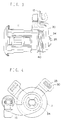
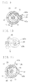
- Fig. 1 is a front view of a cylinder lock device according to an embodiment of the present invention.
- Fig. 2 is a longitudinal-section view of the cylinder lock device.
- Fig. 3 is a side view of the cylinder lock device.
- Fig. 4 is a rear view of the cylinder lock device.
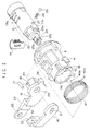
- Fig. 5 is an exploded view of the cylinder lock device.
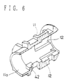
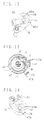
- Fig. 6 is a perspective view showing longitudinal section of a casing.
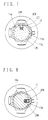
- Fig. 7 is a cross-section view of the cylinder lock device in the neutral position showing a ball and a spring.
- Fig. 8 is a cross-section view of the cylinder lock device in the dead-locked position showing the ball and the spring.
- Fig. 9 is a cross-section view of the cylinder lock device in the neutral position showing a blocking member.
- Fig. 10 is a rear view showing a lever and a bracket in the neutral position.
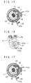
- Fig. 11 is a cross-section view showing the blocking member in the unlocked position.
- Fig. 12 is a rear view showing the lever and the bracket in the unlocked position.
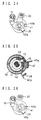
- Fig. 13 is a cross-section view of the cylinder lock device with the key cylinder angularly rotated by 45 degrees from the neutral toward the locked position.
- Fig. 14 is a rear view of the cylinder lock device with the key cylinder angularly rotated by 45 degrees from the neutral toward the locked position.
- Fig. 15 is a cross-section view of the cylinder lock device with the key cylinder angularly rotated by 60 degrees from the neutral toward the locked position.
- Fig. 16 is a rear view of the cylinder lock device with the key cylinder angularly rotated by 60 degrees from the neutral toward the locked position.
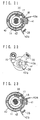
- Fig. 17 is a cross-section view of the cylinder lock device with the key cylinder angularly rotated by 75 degrees from the neutral toward the locked position.
- Fig. 18 is a rear view of the cylinder lock device with the key cylinder angularly rotated by 75 degrees from the neutral toward the locked position.
- Fig. 19 is a cross-section view of the cylinder lock device with the blocking member returned from the angular position of Fig. 17 by a coiled spring to an angular position of 48.5 degrees.
- Fig. 20 is a rear view of the cylinder lock device with the lever and the bracket returned from the angular position of Fig. 18 by the coiled spring to the angular position of 48.5 degrees.
- Fig. 21 is a cross-section view of the cylinder lock device with the key cylinder in the dead-locked position.
- Fig. 22 is a rear view of the cylinder lock devices with the lever and the bracket in the dead-locked position.
- Fig. 23 is a cross-section view of the cylinder lock device with the key cylinder returned to the angular position of 60 degrees.
- Fig. 24 is a rear view of the cylinder lock device with the bracket returned to the angular position of 60 degrees.
- Fig. 25 is a cross-section view of the cylinder lock device with the key cylinder returned to the angular position of 48.5 degrees.
- Fig. 26 is a rear view of the cylinder lock device with the bracket returned to the angular position of 48.5 degrees.
- Fig. 27 is a cross-section view of the cylinder lock device with the key cylinder returned to the angular position of 48 degrees.
- Fig. 28 is a rear view of the cylinder lock device with the lever returned to the angular position of 48 degrees.
- Fig. 29 is a cross-section view of the cylinder lock device with the key cylinder returned to the angular of 30 degrees.
- Fig. 30 is a rear view of the cylinder lock device with the lever and bracket returned to the angular position of 30 degrees.
-
- Referring to Fig. 1 to Fig. 30, an embodiment of the cylinder lock device according to the present invention will be described as follows.
- The
cylinder lock device 10 according to the present invention comprises acasing 11 formed with ahole 11a and fourlongitudinal grooves 12, akey cylinder 13 rotatably disposed within thehole 11a of thecasing 11 andtumblers 14 slidably disposed withinslots 13a formed in thekey cylinder 13. Thegrooves 12 are formed at angular intervals of 90 degrees on aninner wall 11c of thehole 11a of thecasing 11 such that thetumblers 14 are moved between their retracted position within theslots 13a for rotation of thekey cylinder 13 and extended position projecting from theslots 13a for engagement with thegrooves 12, similarly to prior art cylinder locks. A key may be inserted into and pulled out from thekey cylinder 13 when thetumblers 14 move into and away from thegrooves 12. - A
lever 15 has acentral hole 24 to receive acentral protrusion 25 of thekey cylinder 13 so that a cylindrical portion 25a of thecentral protrusion 25 is in contact with thehole 24. Thelever 15 has also anarm 23 formed with ahole 22 to receive a rod (not shown) drivingly connected with a door locking device of a vehicle door; a pair ofarcuate lugs 20 rotatably disposed between thecasing 11 and the key cylinder 13 (Fig. 9); and anotch 16 axially extending between thesearcuate lugs 20. A blockingmember 17 of for example a roller or ball is disposed in thenotch 16 and on aU-shaped chamfer 19 formed in thekey cylinder 13. - A
bracket 30 is attached to the end portion of thekey cylinder 13 adjacent to and outward of thelever 15. Thebracket 30 has anopening 31 of substantially oval or non-circular shape in section to receive a notchedportion 25b of thecentral protrusion 25 of thekey cylinder 13 for integral rotation of thebracket 30 and thekey cylinder 13. Amagnet 33 is secured in arecess 32 formed at the end portion of thebracket 30. As shown in Fig. 3, anE-shaped ring 34 is attached to anannular recess 25c of thecenter protrusion 25 outward of thebracket 30 to prevent detachment of thelever 15 and thebracket 30 from thecenter protrusion 25. - As shown in Fig. 9, wound around the
casing 11 is acoiled spring 40 having twoends lugs lever 15 andcasing 11 are positioned in a radially overlapped condition so that thecoiled spring 40 applies an elastic returning force to thekey cylinder 13 when thekey cylinder 13 is rotated from the neutral position of Fig 9 in either direction. Thekey cylinder 13 has an integrally formedprotrusion 13b which is brought into contact with a stopper or lug 42 formed on theinner wall 11c of thehole 11a of thecasing 11 to bar further rotation of thekey cylinder 13 when thekey cylinder 13 is rotated to the dead-locked position. Also, when thelever 15 is fully rotated together with thekey cylinder 13, either of thearcuate lugs 20 of thelever 15 is brought into contact with thestopper 42 to restrict further rotation of thelever 15. - A
spring 28 and aball 29 are disposed in aradial hole 27 formed in thekey cylinder 13 as shown in Fig. 7 to resiliently urge theball 29 by thespring 28 against theinner wall 11c of thecasing 11 so that theball 29 is engaged with a V-shaped recess 11b formed on theinner wall 11c of thecasing 11 for click stop when thekey cylinder 13 is rotated to the dead-locked position as shown in Figs. 8, 21 and 22. Anaxial concavity 18 is formed on theinner wall 11c of thecasing 11 to receive the blockingmember 17 when thelever 15 is in the locked position. - When the
cylinder lock device 10 is in the inoperative condition, thekey cylinder 13,lever 15, blockingmember 17 andbracket 30 are in the neutral position of Figs. 9 and 10 wherein the blockingmember 17 is received within thenotch 16 of thelever 15 and on theU-shaped chamfer 19 of thekey cylinder 13. When a key is inserted into thekey cylinder 13 in the neutral position of Figs. 9 and 10 and then rotated in a counterclockwise direction, thekey cylinder 13 is rotated in the same direction together with thelever 15, blockingmember 17 andbracket 30 to the unlocked position as shown in Figs. 11 and 12. During the counterclockwise rotation, the blockingmember 17 serves to connect thekey cylinder 13 and thelever 15 for their integral rotation. In the unlocked position, one of thearcuate lugs 20 is brought into contact with thelug 42 of thecasing 11 to stop rotation of thekey cylinder 13 andlever 15, and thereby thearm 23 makes a locking device in the unlocking condition via a rod connected with thehole 22. Simultaneously, thelever 15 is rotated to the unlocked position so that themagnet 33 is detected by a ferrous sensor (not shown) which produces an electric signal representing that thebracket 30 is in the unlocked position. - The
coiled spring 40 produces a returning force of thelever 15 when rotated to the unlocked position because the L-shapedlug 26 of thelever 15 is in contact with oneend 40a of the expandedspring 40. Accordingly, when thekey cylinder 13 is rotated to the unlocked position and a manual rotating force in the counterclockwise direction is removed from the key, thekey cylinder 13,lever 15 andbracket 30 are automatically returned from the unlocked to the neutral position by resilient force of the coiledspring 40. - Adversely, when the key is rotated to the locked position, the
key cylinder 13 is rotated in the clockwise direction as shown in Figs. 13 and 14 from the neutral position toward the locked position together with thelever 15, blockingmember 17 andbracket 30. When thekey cylinder 13 reaches the locked position of Figs. 15 and 16, one of thearcuate lugs 20 comes into contact with thelug 42 of thecasing 11 to stop rotation of thelever 15 so that the locking device is locked by the rod connected with thelever 15 and the magnet sensor detects the locked position of themagnet 33 attached to thebracket 30. At this time, theother end 40b of thecoil spring 40 resiliently urges the L-shapedlug 26 to rotate thelever 15 toward the neutral position so that thekey cylinder 13 automatically returns to the neutral position when rotating force is removed from the key. - When the
lever 15 is stopped in the locked position due to contact of one of thearcuate lugs 20 with thelug 42 of thecasing 11, thekey cylinder 13 is further rotated in the clockwise direction with the key from the locked position shown in Figs. 15 and 16 to the dead-locked position shown in Figs. 21 and 22. The blockingmember 17 in thenotch 16 of thelever 15 moves away from theU-shaped chamfer 19 into theconcavity 18 of thecasing 11 as shown in Fig. 17, and therefore thelever 15 is slightly reversely rotated in the counterclockwise direction by elastic force of thecoil spring 40 as shown in Figs. 19 and 20 so that the blockingmember 17 is moved to contact an edge of theconcavity 18. With a further clockwise rotation, thekey cylinder 13 may be rotated to the dead-locked position shown in Figs. 21 and 22. As the dead-locked position of Figs. 21 and 22 is angularly away from the neutral position of Figs. 9 and 10 by 90 degrees, the key may be pulled out from thekey cylinder 13 with thetumblers 14 protruded within thegroove 12. Thus, in the dead-locked position of thekey cylinder 13, thelever 15 is firmly fixed in the locked position together with cooperating parts drivingly connected with thelever 15 so that thekey cylinder 13 is barred to be returned to the neutral position, causing prevention of unauthorized unlocking by tampering operation of the relating parts of the locking device with tools. - To return the
key cylinder 13 from the dead-locked position to the neutral position, a key is inserted into thekey cylinder 13 in the dead-locked position and then rotated in the counterclockwise direction from the dead-locked position of Figs. 21 and 22 through the position of Figs. 23 and 24 to the position shown in Figs. 25 and 26 in which theU-shaped chamfer 19 of thekey cylinder 13 aligns with thenotch 26 of thelever 15 so that the blockingmember 17 moves away from theconcavity 18 into theU-shaped chamfer 19 of thekey cylinder 13 as shown in Figs. 27 and 28. In this stage, thekey cylinder 13 is automatically returned under elastic force of the coiledspring 40 together with thelever 15 to the neutral position of Figs. 9 and 10 via the position of Figs. 29 and 30. - As above-mentioned, when the
key cylinder 13 is rotated from the neutral or unlocked position to the locked position, the blockingmember 17 in thenotch 16 of thelever 15 is rotated together with thecylinder 13 in contact with thechamfer 19 of thekey cylinder 13. When thekey cylinder 13 is further rotated from the locked position to the dead-locked position, the blockingmember 17 is disengaged from thechamfer 19 of thekey cylinder 13 and received in theconcavity 18 of thecasing 11 to prevent returning rotation of thelever 15 due to engagement of the blockingmember 17 with theconcavity 18 of thecasing 11. When thekey cylinder 13 is further rotated from the locked to the dead-locked position, the key can be pulled out from thekey cylinder 13 to firmly retain thelever 15 and relating parts in the locked position, preventing tampering of the locking device for unauthorized unlocking. In this way, the key can be inserted into and pulled out from thekey cylinder 13 at both of the neutral and dead-locked positions. - The modes of the present invention are not necessarily limited to the aforementioned embodiment, and may be modified in other ways. For example, an alarm device is connected to operate for indication of unauthorized unlocking when the locking device is shifted to the unlocked condition despite of the
magnet 33 of thebracket 30 in the locked position. - In aforementioned embodiment, the
key cylinder 13 can be rotated in opposite directions from the neutral to the unlocked or locked position, however, the structural design may be varied to rotate thekey cylinder 13 in the full angular range of 360 degrees without thecoiled spring 40. - In the cylinder lock device according to the present invention, unauthorized unlocking by, for example, tampering the relating parts such as a lock nob cooperating with the locking device by use of tools, is perfectly prevented as these parts are firmly fixed in the locked position by keeping the key cylinder in the dead-locked position.
Claims (13)
- A cylinder lock device comprising a casing (11) which has a plurality of grooves (12) formed in said casing; a key cylinder (13) rotatably disposed within said casing (11), said key cylinder (13) having slots (13a) formed therein; and tumblers (14) slidably disposed in said slots (13a) of said key cylinder (13) for engagement with or disengagement from said grooves (12) of said casing (11);a lever (15) rotatably mounted on said key cylinder (13), a notch (16) formed in said lever (15);a concavity (18) formed on an inner wall of said casing (11);a chamfer (19) formed in the key cylinder (13); anda blocking member (17) disposed within said notch (16) of said lever (15) for rotation together with said lever (15) from an unlocked or neutral position to a locked position, said blocking member (17) also being received within said chamfer (19) of the key cylinder (13) when the lock device is moved from said unlocked or neutral position to said locked position, the blocking member (17) thereby serving to connect the key cylinder (13) and the lever (15) for integral rotation during said movement from said unlocked or neutral position to said locked position;the key cylinder (13) being capable of being rotated from the locked to a dead-locked position so that said blocking member (17) moves away from the chamfer (19) into said concavity (18) of said casing (11) to forcibly maintain the lever (15) and a locking device to which the lever, in use, is connected in the locked position for preventing returning rotation of said lever (15) to the neutral or unlocked position via said blocking member (17) being engaged in said notch (16) and concavity (18).
- A cylinder lock device as claimed in claim 1, characterised in that said blocking member (17) is retained within the notch (16) of said lever (15) on said chamfer (19) of said key cylinder (13) for rotation together with said key cylinder when said key cylinder (13) is rotated from the neutral or unlocked position to the locked position,said blocking member (17) moving away from said chamfer (19) of said key cylinder (13) and into the concavity (18) of said casing (11) when the key cylinder (13) is farther rotated over the locked position to the dead-locked position.
- A cylinder lock device as claimed in claim 1 or 2, characterised in that said blocking member (17) is a roller or ball.
- A cylinder lock device as claimed in Claim 1, characterised in that said grooves (12) are formed in said casing (11) at angular intervals of 90 degrees; said blocking member (17) being disposed within the notch (16) and on the chamfer (19) for rotation with said key cylinder (13) from the neutral or unlocked position to the unlocked position,said blocking member (17) being movable away from said chamfer (19) of said key cylinder (13) into said concavity (18) upon the rotation of said key cylinder from the locked to said dead-locked position to prevent said lever (15) from returning to said un-locked position by rotation in said casing (11).
- A cylinder lock device as claimed in claim 4, wherein a key can be pulled from or inserted into said key cylinder (13) in the dead-locked position of said key cylinder (13).
- A cylinder lock device as claimed in claim 4, wherein a key can be inserted into or pulled from said key cylinder (13) in the neutral or unlocked position of the key cylinder (13).
- A cylinder lock device as claimed in claim 4, wherein said lever (15) rotates with said blocking member (17) retained in the notch (16) of said lever (15) when the key cylinder (13) is rotated by a key until said blocking member (17) is received within the concavity (18) of said casing.
- A cylinder lock device as claimed in any one of claims 1 to 7, wherein said lever (15) has a pair of arcuate lugs (20) to form the notch (16).
- A cylinder lock device as claimed in any one of claims 1 to 8, wherein a bracket (30) is secured to said key cylinder (13) for rotation between the unlocked and dead-locked positions.
- A cylinder lock device as claimed in claim 9, wherein said bracket (30) has a magnet (33) which is detected by a magnetic sensor to indicate the position of the key cylinder (13).
- A cylinder lock device as claimed in any one of the preceding claims, wherein said key cylinder (13) is rotatable in a first direction for achieving said dead-locked position, said dead-locked position comprising said tumblers (14) in said key cylinder (13) being engaged with one of said grooves (12) at a position beyond the locked position toward said first direction, wherein at said dead-locked position said blocking member (17) remains engaged with said concavity (18) and said tumblers (14) remain engaged in said one of said grooves (12).
- A cylinder lock device as claimed in anyone of claims 1 to 11 wherein the blocking member (17) establishes the dead-locked position as defined by said lever (15) locked to said casing, and wherein the lever (15) has a pair of arcuate lugs (20) and further comprising a stopper (42) formed in said casing (11) for preventing further rotation of said lever (15) when it reaches said unlocked position due to contact between at least one of said arcuate lugs (20) and stopper (42).
- A cylinder lock device as claimed in of claim 12, wherein said lever (15) is adapted to engage with said stopper (42) in the locked position for stopping the rotation thereof and allowing relative motion between said key cylinder (13) and said lever (15) for establishing said dead-locked position.
Priority Applications (4)
| Application Number | Priority Date | Filing Date | Title |
|---|---|---|---|
| CA 2120194 CA2120194C (en) | 1994-03-29 | 1994-03-29 | Cylinder lock device resistible against unauthorized unlocking |
| US08/219,089 US5428978A (en) | 1994-03-29 | 1994-03-29 | Cylinder lock device resistible against unauthorized unlocking |
| DE1994626015 DE69426015T3 (en) | 1994-03-30 | 1994-03-30 | Cylinder lock device secured against unauthorized unlocking |
| EP19940302310 EP0675248B2 (en) | 1994-03-29 | 1994-03-30 | Cylinder lock device resistible against unauthorized unlocking |
Applications Claiming Priority (3)
| Application Number | Priority Date | Filing Date | Title |
|---|---|---|---|
| CA 2120194 CA2120194C (en) | 1994-03-29 | 1994-03-29 | Cylinder lock device resistible against unauthorized unlocking |
| US08/219,089 US5428978A (en) | 1994-03-29 | 1994-03-29 | Cylinder lock device resistible against unauthorized unlocking |
| EP19940302310 EP0675248B2 (en) | 1994-03-29 | 1994-03-30 | Cylinder lock device resistible against unauthorized unlocking |
Publications (3)
| Publication Number | Publication Date |
|---|---|
| EP0675248A1 EP0675248A1 (en) | 1995-10-04 |
| EP0675248B1 true EP0675248B1 (en) | 2000-09-27 |
| EP0675248B2 EP0675248B2 (en) | 2006-10-25 |
Family
ID=27169736
Family Applications (1)
| Application Number | Title | Priority Date | Filing Date |
|---|---|---|---|
| EP19940302310 Expired - Lifetime EP0675248B2 (en) | 1994-03-29 | 1994-03-30 | Cylinder lock device resistible against unauthorized unlocking |
Country Status (3)
| Country | Link |
|---|---|
| US (1) | US5428978A (en) |
| EP (1) | EP0675248B2 (en) |
| CA (1) | CA2120194C (en) |
Families Citing this family (34)
| Publication number | Priority date | Publication date | Assignee | Title |
|---|---|---|---|---|
| JPH0726816A (en) * | 1993-07-14 | 1995-01-27 | Nissan Motor Co Ltd | Door lock device |
| DE4412609A1 (en) * | 1994-04-13 | 1995-10-19 | Huelsbeck & Fuerst | Locking device for locking functions that can be performed in particular on motor vehicles |
| JP3298737B2 (en) * | 1994-04-28 | 2002-07-08 | 株式会社アルファ | Key cylinder automatic return device for cylinder lock device |
| JP3167862B2 (en) * | 1994-06-30 | 2001-05-21 | 三井金属鉱業株式会社 | Door lock device with anti-theft mechanism |
| US5615565A (en) * | 1995-09-19 | 1997-04-01 | Medeco Security Locks, Inc. | Keys for cylinder locks |
| PT907816E (en) * | 1996-07-04 | 2002-05-31 | Huf Huelsbeck & Fuerst Gmbh | HARNESSES FOR DOORS COVERS COVERS OF SUITCASES OR SIMILAR IN VEHICLES SPECIAL, FOR EXAMPLE AUTOMOVEIS |
| US6105405A (en) * | 1998-11-25 | 2000-08-22 | Wesko Systems Limited | Locking apparatus having a unitary driver |
| DE10162201A1 (en) * | 2000-12-20 | 2002-07-11 | Tokai Rika Co Ltd | Key cylinder and method for assembling a key cylinder |
| US7634930B2 (en) | 2002-01-03 | 2009-12-22 | Strattec Security Corporation | Lock apparatus and method |
| US6711924B2 (en) * | 2002-06-18 | 2004-03-30 | Strattec Security Corporation | Freewheeling lock apparatus and method |
| US7114357B2 (en) | 2002-09-26 | 2006-10-03 | Newfrey, Llc | Keying system and method |
| US8347678B2 (en) * | 2002-09-26 | 2013-01-08 | Newfrey, Llc | Rekeyable lock cylinder assembly |
| US6862909B2 (en) | 2002-09-26 | 2005-03-08 | Newfrey Llc | Devices, methods, and systems for keying a lock assembly |
| US6860131B2 (en) * | 2002-09-26 | 2005-03-01 | Newfrey Llc | Rekeying a lock assembly |
| US6959569B2 (en) * | 2002-09-26 | 2005-11-01 | Newfrey Llc | Re-keyable lock assembly |
| US6951123B2 (en) | 2003-03-05 | 2005-10-04 | Newfrey Llc | Rekeyable lock |
| US6978645B2 (en) * | 2003-06-23 | 2005-12-27 | Strattec Security Corporation | Freewheeling lock apparatus and method |
| JP4675238B2 (en) * | 2003-09-12 | 2011-04-20 | 株式会社ユーシン | Cylinder lock |
| US6973813B2 (en) * | 2003-12-05 | 2005-12-13 | Newfrey Llc | Re-keyable lock and method |
| US7007528B2 (en) | 2004-04-01 | 2006-03-07 | Newfrey Llc | Re-keyable lock cylinder |
| US20060059965A1 (en) * | 2004-09-17 | 2006-03-23 | Benstead Evan A | Rekeyable lock having 2-piece pin with rotatable member |
| US20060101880A1 (en) * | 2004-11-12 | 2006-05-18 | Ward-Dolkas Paul C | Re-keyable lock cylinder |
| FR2882771B1 (en) * | 2005-03-04 | 2008-09-05 | Valeo Securite Habitacle Sas | DEBRAYABLE LATCH FOR AUTOMOBILE LOCK MECHANISM |
| FR2882772B1 (en) * | 2005-03-04 | 2007-05-04 | Valeo Securite Habitacle Sas | DEBRAYABLE LATCH FOR AUTOMOBILE LOCK MECHANISM |
| FR2883322B1 (en) * | 2005-03-18 | 2008-09-05 | Valeo Securite Habitacle Sas | DEBRAYABLE LATCH FOR AUTOMOBILE LOCK MECHANISM |
| US8881567B2 (en) * | 2005-10-21 | 2014-11-11 | Kwikset Corporation | Reset fixture for rekeyable lock assembly |
| US7775071B2 (en) * | 2006-11-02 | 2010-08-17 | Inner-Tite Corp. | Pre-loaded barrel lock |
| US8099988B1 (en) | 2010-08-09 | 2012-01-24 | Newfrey, Llc | Tool-less rekeyable lock cylinder |
| JP5292386B2 (en) * | 2010-12-22 | 2013-09-18 | 株式会社ホンダロック | Central unlocking device |
| US8291735B1 (en) | 2011-03-31 | 2012-10-23 | Newfrey, Llc | Rekeyable lock cylinder having rotatable key followers |
| US9512642B2 (en) * | 2014-03-07 | 2016-12-06 | Keyless.Co, Llc | Reprogrammable cylinder lock |
| WO2017096369A1 (en) * | 2015-12-03 | 2017-06-08 | I-Lock Security Products, Llc. | Tamper resistant locking device |
| US11319726B2 (en) | 2018-10-22 | 2022-05-03 | Spectrum Brands, Inc. | Tool-less rekeyable lock cylinder |
| CN109935492A (en) * | 2019-04-19 | 2019-06-25 | 江苏吉野电气有限公司 | The elevator lock that automatically resets with striking gear |
Family Cites Families (14)
| Publication number | Priority date | Publication date | Assignee | Title |
|---|---|---|---|---|
| US3197985A (en) * | 1962-05-04 | 1965-08-03 | Cosio Othon Orozco | Combination for locks with movable toggle holder and safety dome |
| US3659444A (en) * | 1970-04-30 | 1972-05-02 | John F Wellekens | Locks |
| CH621847A5 (en) * | 1977-06-06 | 1981-02-27 | Saseb Ag | Locking arrangement on a vehicle |
| US4326396A (en) * | 1980-01-14 | 1982-04-27 | Chicago Lock Co. | Plate tumbler for a cylinder lock mechanism |
| US4395893A (en) * | 1981-08-03 | 1983-08-02 | Chicago Lock Co. | Plate tumbler-type cylinder lock mechanism |
| US4563885A (en) * | 1982-04-08 | 1986-01-14 | Excalibur Locks, Inc. | Patio sliding door lock assembly and method |
| FR2557623B1 (en) * | 1983-12-28 | 1986-04-25 | Neiman Sa | DEVICE FOR RELEASING A LOCKING MECHANISM WITH A CONVICTION |
| DE3513287A1 (en) * | 1985-04-13 | 1986-10-16 | Hülsbeck & Fürst GmbH & Co KG, 5620 Velbert | Locking device for locking a motor-vehicle door, preferably of passenger cars |
| US4829798A (en) * | 1987-10-07 | 1989-05-16 | Medeco Security Locks, Inc. | Combination switch lock/cam lock assembly |
| JP2793237B2 (en) * | 1989-03-31 | 1998-09-03 | 日産自動車株式会社 | Cylinder lock |
| US5265453A (en) * | 1990-11-30 | 1993-11-30 | Alpha Corporation | Cylinder lock |
| DE4215560A1 (en) * | 1991-08-14 | 1993-04-15 | Fuhr Carl Gmbh & Co | Cylinder lock which can be operated from either side - has knob which is connected by coupling to link cylinder |
| DE4202698C2 (en) * | 1992-01-31 | 1995-11-02 | Huelsbeck & Fuerst | Lock for doors, hoods or the like, in particular of vehicles, such as motor vehicles |
| DE4316223A1 (en) * | 1992-05-18 | 1993-11-25 | Ewald Witte Gmbh & Co Kg | Car door lock cylinder with core in housing - has spring-loaded coupling position with coupling springs abutting locking member |
-
1994
- 1994-03-29 CA CA 2120194 patent/CA2120194C/en not_active Expired - Fee Related
- 1994-03-29 US US08/219,089 patent/US5428978A/en not_active Expired - Lifetime
- 1994-03-30 EP EP19940302310 patent/EP0675248B2/en not_active Expired - Lifetime
Also Published As
| Publication number | Publication date |
|---|---|
| CA2120194C (en) | 1999-08-03 |
| US5428978A (en) | 1995-07-04 |
| CA2120194A1 (en) | 1995-09-30 |
| EP0675248B2 (en) | 2006-10-25 |
| EP0675248A1 (en) | 1995-10-04 |
Similar Documents
| Publication | Publication Date | Title |
|---|---|---|
| EP0675248B1 (en) | Cylinder lock device resistible against unauthorized unlocking | |
| US5265453A (en) | Cylinder lock | |
| EP0659962B1 (en) | Cylinder lock resistible against breaking | |
| US5816086A (en) | Axial moving pushbutton for a lock having rotary locking and release motions | |
| US5285667A (en) | Cylinder lock | |
| US6604393B2 (en) | Lock system operable with multiple keys | |
| CN1075588C (en) | Locking device containing cylinder lock with main execution locking function for vehicle | |
| JPH02292475A (en) | Locking mechanism | |
| US4416129A (en) | Cylinder lock with key removable plug | |
| US4333325A (en) | Steering shaft locking device | |
| US6446475B1 (en) | Switchlock assembly with snap-in cam | |
| US5884510A (en) | Bolt lock | |
| US7339472B2 (en) | Self-adjusting cam assembly | |
| CA2241542C (en) | Key controlled latch | |
| US5706681A (en) | Antitheft locking device for a vehicle | |
| EP0679782B1 (en) | Key cylinder automatic returning device for cylinder lock device | |
| EP0488787B1 (en) | Cylinder lock | |
| US5709115A (en) | Sidebar ignition lock | |
| US4854140A (en) | Plunger lock mechanism | |
| CA2808699C (en) | Self-adjusting cam assembly | |
| US11795728B2 (en) | Cylinder lock | |
| JPH0332215Y2 (en) | ||
| JPH0321581Y2 (en) | ||
| JPH0658074U (en) | Cylinder lock | |
| JPH08120982A (en) | Cylinder lock |
Legal Events
| Date | Code | Title | Description |
|---|---|---|---|
| PUAI | Public reference made under article 153(3) epc to a published international application that has entered the european phase |
Free format text: ORIGINAL CODE: 0009012 |
|
| AK | Designated contracting states |
Kind code of ref document: A1 Designated state(s): BE CH DE ES FR GB IT LI NL SE |
|
| 17P | Request for examination filed |
Effective date: 19960208 |
|
| 17Q | First examination report despatched |
Effective date: 19960327 |
|
| GRAG | Despatch of communication of intention to grant |
Free format text: ORIGINAL CODE: EPIDOS AGRA |
|
| GRAG | Despatch of communication of intention to grant |
Free format text: ORIGINAL CODE: EPIDOS AGRA |
|
| GRAH | Despatch of communication of intention to grant a patent |
Free format text: ORIGINAL CODE: EPIDOS IGRA |
|
| GRAH | Despatch of communication of intention to grant a patent |
Free format text: ORIGINAL CODE: EPIDOS IGRA |
|
| GRAA | (expected) grant |
Free format text: ORIGINAL CODE: 0009210 |
|
| AK | Designated contracting states |
Kind code of ref document: B1 Designated state(s): BE CH DE ES FR GB IT LI NL SE |
|
| PG25 | Lapsed in a contracting state [announced via postgrant information from national office to epo] |
Ref country code: NL Free format text: LAPSE BECAUSE OF FAILURE TO SUBMIT A TRANSLATION OF THE DESCRIPTION OR TO PAY THE FEE WITHIN THE PRESCRIBED TIME-LIMIT Effective date: 20000927 Ref country code: LI Free format text: LAPSE BECAUSE OF FAILURE TO SUBMIT A TRANSLATION OF THE DESCRIPTION OR TO PAY THE FEE WITHIN THE PRESCRIBED TIME-LIMIT Effective date: 20000927 Ref country code: ES Free format text: THE PATENT HAS BEEN ANNULLED BY A DECISION OF A NATIONAL AUTHORITY Effective date: 20000927 Ref country code: CH Free format text: LAPSE BECAUSE OF FAILURE TO SUBMIT A TRANSLATION OF THE DESCRIPTION OR TO PAY THE FEE WITHIN THE PRESCRIBED TIME-LIMIT Effective date: 20000927 Ref country code: BE Free format text: LAPSE BECAUSE OF FAILURE TO SUBMIT A TRANSLATION OF THE DESCRIPTION OR TO PAY THE FEE WITHIN THE PRESCRIBED TIME-LIMIT Effective date: 20000927 |
|
| REG | Reference to a national code |
Ref country code: CH Ref legal event code: EP |
|
| REF | Corresponds to: |
Ref document number: 69426015 Country of ref document: DE Date of ref document: 20001102 |
|
| ITF | It: translation for a ep patent filed |
Owner name: STUDIO TORTA S.R.L. |
|
| PG25 | Lapsed in a contracting state [announced via postgrant information from national office to epo] |
Ref country code: SE Free format text: LAPSE BECAUSE OF FAILURE TO SUBMIT A TRANSLATION OF THE DESCRIPTION OR TO PAY THE FEE WITHIN THE PRESCRIBED TIME-LIMIT Effective date: 20001227 |
|
| REG | Reference to a national code |
Ref country code: FR Ref legal event code: RN |
|
| EN | Fr: translation not filed | ||
| PG25 | Lapsed in a contracting state [announced via postgrant information from national office to epo] |
Ref country code: FR Free format text: LAPSE BECAUSE OF FAILURE TO SUBMIT A TRANSLATION OF THE DESCRIPTION OR TO PAY THE FEE WITHIN THE PRESCRIBED TIME-LIMIT Effective date: 20010223 |
|
| REG | Reference to a national code |
Ref country code: FR Ref legal event code: FC |
|
| NLV1 | Nl: lapsed or annulled due to failure to fulfill the requirements of art. 29p and 29m of the patents act | ||
| ET | Fr: translation filed | ||
| REG | Reference to a national code |
Ref country code: CH Ref legal event code: PL |
|
| PLBQ | Unpublished change to opponent data |
Free format text: ORIGINAL CODE: EPIDOS OPPO |
|
| PLBI | Opposition filed |
Free format text: ORIGINAL CODE: 0009260 |
|
| 26 | Opposition filed |
Opponent name: HUF HUELSBECK & FUERST GMBH. & CO. KG. Effective date: 20010618 |
|
| REG | Reference to a national code |
Ref country code: GB Ref legal event code: IF02 |
|
| PLBF | Reply of patent proprietor to notice(s) of opposition |
Free format text: ORIGINAL CODE: EPIDOS OBSO |
|
| PLBF | Reply of patent proprietor to notice(s) of opposition |
Free format text: ORIGINAL CODE: EPIDOS OBSO |
|
| PLAY | Examination report in opposition despatched + time limit |
Free format text: ORIGINAL CODE: EPIDOSNORE2 |
|
| PLBC | Reply to examination report in opposition received |
Free format text: ORIGINAL CODE: EPIDOSNORE3 |
|
| PUAH | Patent maintained in amended form |
Free format text: ORIGINAL CODE: 0009272 |
|
| STAA | Information on the status of an ep patent application or granted ep patent |
Free format text: STATUS: PATENT MAINTAINED AS AMENDED |
|
| 27A | Patent maintained in amended form |
Effective date: 20061025 |
|
| AK | Designated contracting states |
Kind code of ref document: B2 Designated state(s): BE CH DE ES FR GB IT LI NL SE |
|
| REG | Reference to a national code |
Ref country code: ES Ref legal event code: FD2A Effective date: 20010331 |
|
| ET3 | Fr: translation filed ** decision concerning opposition | ||
| PGFP | Annual fee paid to national office [announced via postgrant information from national office to epo] |
Ref country code: GB Payment date: 20090325 Year of fee payment: 16 |
|
| PGFP | Annual fee paid to national office [announced via postgrant information from national office to epo] |
Ref country code: IT Payment date: 20090317 Year of fee payment: 16 Ref country code: DE Payment date: 20090327 Year of fee payment: 16 |
|
| PGFP | Annual fee paid to national office [announced via postgrant information from national office to epo] |
Ref country code: FR Payment date: 20090316 Year of fee payment: 16 |
|
| GBPC | Gb: european patent ceased through non-payment of renewal fee |
Effective date: 20100330 |
|
| REG | Reference to a national code |
Ref country code: FR Ref legal event code: ST Effective date: 20101130 |
|
| PG25 | Lapsed in a contracting state [announced via postgrant information from national office to epo] |
Ref country code: DE Free format text: LAPSE BECAUSE OF NON-PAYMENT OF DUE FEES Effective date: 20101001 |
|
| PG25 | Lapsed in a contracting state [announced via postgrant information from national office to epo] |
Ref country code: GB Free format text: LAPSE BECAUSE OF NON-PAYMENT OF DUE FEES Effective date: 20100330 Ref country code: IT Free format text: LAPSE BECAUSE OF NON-PAYMENT OF DUE FEES Effective date: 20100330 |
|
| PG25 | Lapsed in a contracting state [announced via postgrant information from national office to epo] |
Ref country code: FR Free format text: LAPSE BECAUSE OF FAILURE TO SUBMIT A TRANSLATION OF THE DESCRIPTION OR TO PAY THE FEE WITHIN THE PRESCRIBED TIME-LIMIT Effective date: 20100331 |