EP0679766A2 - Removable brush coupling - Google Patents
Removable brush coupling Download PDFInfo
- Publication number
- EP0679766A2 EP0679766A2 EP95302314A EP95302314A EP0679766A2 EP 0679766 A2 EP0679766 A2 EP 0679766A2 EP 95302314 A EP95302314 A EP 95302314A EP 95302314 A EP95302314 A EP 95302314A EP 0679766 A2 EP0679766 A2 EP 0679766A2
- Authority
- EP
- European Patent Office
- Prior art keywords
- legs
- brush
- recess
- projection
- hub
- Prior art date
- Legal status (The legal status is an assumption and is not a legal conclusion. Google has not performed a legal analysis and makes no representation as to the accuracy of the status listed.)
- Withdrawn
Links
Images

Classifications
-
- A—HUMAN NECESSITIES
- A47—FURNITURE; DOMESTIC ARTICLES OR APPLIANCES; COFFEE MILLS; SPICE MILLS; SUCTION CLEANERS IN GENERAL
- A47L—DOMESTIC WASHING OR CLEANING; SUCTION CLEANERS IN GENERAL
- A47L11/00—Machines for cleaning floors, carpets, furniture, walls, or wall coverings
- A47L11/40—Parts or details of machines not provided for in groups A47L11/02 - A47L11/38, or not restricted to one of these groups, e.g. handles, arrangements of switches, skirts, buffers, levers
- A47L11/4036—Parts or details of the surface treating tools
-
- A—HUMAN NECESSITIES
- A47—FURNITURE; DOMESTIC ARTICLES OR APPLIANCES; COFFEE MILLS; SPICE MILLS; SUCTION CLEANERS IN GENERAL
- A47L—DOMESTIC WASHING OR CLEANING; SUCTION CLEANERS IN GENERAL
- A47L11/00—Machines for cleaning floors, carpets, furniture, walls, or wall coverings
- A47L11/02—Floor surfacing or polishing machines
- A47L11/10—Floor surfacing or polishing machines motor-driven
- A47L11/14—Floor surfacing or polishing machines motor-driven with rotating tools
- A47L11/16—Floor surfacing or polishing machines motor-driven with rotating tools the tools being disc brushes
- A47L11/164—Parts or details of the brushing tools
-
- A—HUMAN NECESSITIES
- A47—FURNITURE; DOMESTIC ARTICLES OR APPLIANCES; COFFEE MILLS; SPICE MILLS; SUCTION CLEANERS IN GENERAL
- A47L—DOMESTIC WASHING OR CLEANING; SUCTION CLEANERS IN GENERAL
- A47L11/00—Machines for cleaning floors, carpets, furniture, walls, or wall coverings
- A47L11/40—Parts or details of machines not provided for in groups A47L11/02 - A47L11/38, or not restricted to one of these groups, e.g. handles, arrangements of switches, skirts, buffers, levers
- A47L11/4036—Parts or details of the surface treating tools
- A47L11/4038—Disk shaped surface treating tools
-
- A—HUMAN NECESSITIES
- A47—FURNITURE; DOMESTIC ARTICLES OR APPLIANCES; COFFEE MILLS; SPICE MILLS; SUCTION CLEANERS IN GENERAL
- A47L—DOMESTIC WASHING OR CLEANING; SUCTION CLEANERS IN GENERAL
- A47L11/00—Machines for cleaning floors, carpets, furniture, walls, or wall coverings
- A47L11/40—Parts or details of machines not provided for in groups A47L11/02 - A47L11/38, or not restricted to one of these groups, e.g. handles, arrangements of switches, skirts, buffers, levers
- A47L11/4063—Driving means; Transmission means therefor
- A47L11/4069—Driving or transmission means for the cleaning tools
-
- E—FIXED CONSTRUCTIONS
- E01—CONSTRUCTION OF ROADS, RAILWAYS, OR BRIDGES
- E01H—STREET CLEANING; CLEANING OF PERMANENT WAYS; CLEANING BEACHES; DISPERSING OR PREVENTING FOG IN GENERAL CLEANING STREET OR RAILWAY FURNITURE OR TUNNEL WALLS
- E01H1/00—Removing undesirable matter from roads or like surfaces, with or without moistening of the surface
- E01H1/02—Brushing apparatus, e.g. with auxiliary instruments for mechanically loosening dirt
- E01H1/05—Brushing apparatus, e.g. with auxiliary instruments for mechanically loosening dirt with driven brushes
- E01H1/053—Brushing apparatus, e.g. with auxiliary instruments for mechanically loosening dirt with driven brushes having vertical axes
-
- Y—GENERAL TAGGING OF NEW TECHNOLOGICAL DEVELOPMENTS; GENERAL TAGGING OF CROSS-SECTIONAL TECHNOLOGIES SPANNING OVER SEVERAL SECTIONS OF THE IPC; TECHNICAL SUBJECTS COVERED BY FORMER USPC CROSS-REFERENCE ART COLLECTIONS [XRACs] AND DIGESTS
- Y10—TECHNICAL SUBJECTS COVERED BY FORMER USPC
- Y10T—TECHNICAL SUBJECTS COVERED BY FORMER US CLASSIFICATION
- Y10T403/00—Joints and connections
- Y10T403/60—Biased catch or latch
- Y10T403/602—Biased catch or latch by separate spring
Definitions
- Brush 26 is affixed to drive shaft 30, and drive hub 38 is trapped within recess 40 simply by pushing brush 26 in an axial, affixing direction toward drive hub 38.
- cam surfaces 60 meet legs 74 and 76 of retainer 42, they will cam or ramp legs 74 and 76 to elastically spread them laterally outward from the initial position shown in Figures 2 and 3 to allow drive hub 38 to be inserted within recess 40.
- relief surfaces 60 will retain legs 74 and 76 in the open or spread position until legs 74 and 76 meet shelf surfaces 62. Legs 74 and 76 will then elastically snap laterally inward until they strike stop surfaces 64 and assume an engaged position, as shown in Figure 7.
Landscapes
- Engineering & Computer Science (AREA)
- Architecture (AREA)
- Civil Engineering (AREA)
- Structural Engineering (AREA)
- Brushes (AREA)
Abstract
A coupling for removably affixing a brush (26) to a rotatable drive shaft includes a drive hub (38) affixed to the drive shaft (30), in which an axial projection having a cam surface (60) is disposed on either the drive hub (38) or the brush (30). The other of the hub and the brush defines a recess (40) for accepting the projection and has a spring retainer (42) affixed thereto. The projection and recess (40) have an interfitting spline connection (54) for preventing relative rotation between the drive hub (38) and the brush (30). The cam surface (60) is adapted to elastically spread the retainer (42) to allow the projection to be inserted within the recess (40). The retainer (42) thereafter engages the shelf surface (62) to prevent removal of the projection from the recess (40). The spring retainer (42) is provided with tabs (78,80) for elastically spreading the retainer (42) the shelf surface (62) and allow the brush (30) to be easily removed from the drive hub (38).
Description
- This invention relates generally to couplings, and more particularly to a unique coupling for removably affixing a brush to a drive shaft.
- Rotating brushes are used in a variety of devices, such as cleaning vehicles, polishing machines, and automated car washing machines. However, the brushes invariably wear out after an extended period of use. At such a time, the bristles, fibers, blades, or wipers of the brush become worn or stiff, or otherwise unusable. As a result, rotating brush machines have been provided with various devices for removably affixing a brush to a drive shaft. Such detachable couplings have included breakable retainers, releasable latches, bayonet retainers, snaps, and clasps. In addition, various snap rings and spring clips have been provided.
- However, removable brush couplings have generally relied on the application of a relatively high force to remove the brush from the drive hub. In other words, the couplings generally provide no means for easily uncoupling or releasing the engagement and removing the brush. This technique may be difficult for an operator to perform, or may result in a component of the coupling breaking while the brush is removed. It is therefore desirable to provide a coupling for removably affixing a brush to a drive hub which includes releasing means for alleviating the engagement of the coupling, thereby allowing the brush to be easily removed from the drive hub.
- Accordingly, the coupling of the present invention provides a novel configuration for a drive hub and a brush, wherein either the drive hub or the brush head is provided with an axially extending projection having a cam surface, while the other defines a recess for receiving the projection and is affixed to a spring retainer. The recess and projection have an interfitting spline connection to prevent relative rotation between the brush and the drive hub. The cam surface is adapted to elastically spread the spring retainer to allow the projection to be inserted within the recess. The retainer thereafter engages the projection to prevent removal of the projection from the recess. The spring retainer is provided with tabs for manually adjusting the spring retainer to an open position in which it no longer engages the projection, allowing the projection to be easily removed from the recess. The coupling of the present invention also allows a brush to be easily reattached to the hub.
- It is therefore an object of the present invention to provide a coupling for removably affixing a brush to a drive hub having releasing means for releasing the coupling to allow easy removal of the brush from the drive hub, whereby the aforementioned problems encountered with known couplings are overcome.
- These and other advantages and features will become apparent from the following description and claims in conjunction with the accompanying drawings.
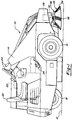
- Figure 1 is a side elevational view of a cleaning vehicle incorporating a coupling according to the principles of the present invention;
- Figure 2 is a perspective view of a coupling according to the present invention;
- Figure 3 is a top plan view of a brush according to the present invention;
- Figure 4 is a partial vertical cross-sectional view of a brush according to the present invention taken generally along lines 4-4 in Figure 3;
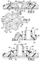
- Figure 5 is a top plan view of a drive hub according to the present invention;
- Figure 6 is a vertical cross-sectional view of the drive hub shown in Figure 5, taken generally along lines 6-6; and
- Figure 7 is a partial vertical cross-sectional view of an assembled coupling according to the present invention.
- The following description of the preferred embodiment is merely exemplary in nature, and is in no way intended to limit the invention or its application or uses.
- With reference to the drawings, Figure 1 shows a
cleaning vehicle 10 for cleaning asurface 12 having a body 14, a pair ofdriving wheels 16, arear steering wheel 18, anengine 20 for movingvehicle 10 uponsurface 12, an operator'schair 22, a conventional arrangement ofcontrols 24 for controlling the operation ofvehicle 10, and arotatable brush 26 disposed at the front ofvehicle 10 for sweeping andcleaning surface 12. Amotor 28 is provided for rotating adrive shaft 30 and thereby for rotatingbrush 26 when one is affixed thereto.Brush 26 is formed of abrush head 32 and a multiplicity ofbristles 34 which are affixed tobrush head 32 by any known method.Brush head 32 is preferably formed of a hard plastic or other rigid material, whilebristles 34 may be made of any of a variety of flexible materials. Of course,brush 26 may be of various types, in which axially extendingbristles 34 are replaced by rubber blades, radially extending bristles, or strips of cloth, for example. - The
novel coupling 36 of the present invention is shown in greater detail in Figures 2-7 and is capable of removably affixingbrush 26 to driveshaft 30, while providing manually actuable releasing means for alleviating the engagement ofcoupling 36 to allowbrush 26 to be easily removed fromdrive shaft 30.Brush 26 may then be replaced by a new brush, or may be reattached to driveshaft 30. The present invention thus provides a unique apparatus for rigidlycoupling brush 26 to driveshaft 30 simply by pushingbrush 26 into position, where coupling 36 elastically and automatically engagesbrush 26.Coupling 36 can then be manually released, andbrush 26 easily removed, in a one-step operation. -
Coupling 36 generally constitutes an axial projection extending from adrive hub 38 which is non-rotatably affixed to an end ofdrive shaft 30, arecess 40 formed onbrush head 32 which is adapted to acceptdrive hub 38, and aspring retainer 42 affixed tobrush head 32 for selectively engaging and releasingdrive hub 38.Drive hub 38 has acylindrical collar 44 which surrounds the end ofdrive shaft 30, akeyway 46 formed incollar 44 for receiving and engaging akey 50 affixed to driveshaft 30, anannular ring 48, adisc 52 extending betweencollar 44 andring 48, and a series of preferably sixsplines 54 projecting radially outward fromring 48.Disc 52 has a number ofpassages 56 extending therethrough.Splines 54 are each formed withtorque applying surfaces 58,cam surfaces 60,shelf surfaces 62,stop surfaces 64, andrelief surfaces 66.Drive hub 38 may be formed havingseveral cam surfaces 60 andseveral shelf surfaces 62, or only one, or a combination thereof.Cam surfaces 60 are inclined with respect torelief surfaces 66 and an axis of rotation ofdrive shaft 30.Shelf surfaces 62 are orthogonal to and extend radially outward from longitudinally extendingstop surfaces 64. Longitudinally extendingrelief surfaces 66 are substantially parallel tostop surfaces 64 and are disposed betweencam surfaces 60 andshelf surfaces 62.Cam surfaces 60 are disposed at an axial end or distal portion ofspines 54, whileshelf surfaces 62 andstop surfaces 64 are disposed at an axially opposite end ofsplines 54. Of course,shelf surfaces 62 andstop surface 64 may be disposed onspines 54 as shown in Figures 2, 5, and 6, or elsewhere ondrive hub 38, such as onannular ring 48. The preferred configuration ofdrive hub 38, havingcollar 44,ring 48, anddisc 52 withpassages 56, rather than a solid block of material, is thus strong yet lightweight. - Recess 40 formed in
brush head 32 has a matching series of preferably sixsplineways 68 havingtorque receiving surfaces 70 for receiving, mating with, and directly engagingsplines 54 to prevent relative rotation betweenbrush head 32 anddrive hub 38.Hub 38 and recess 40 thus form an interfitting spine connection. Splineways 68 preferably also haveinclined surfaces 72 which matchinclined cam surfaces 60 whendrive hub 38 is inserted withinrecess 40. In an alternative embodiment, the drive hub may be formed with a recess similar torecess 40, and the brush head may accordingly have an axial projection having cam surfaces and shelf surfaces similar to the axial end projection ofdrive hub 38. -
Spring retainer 42 is mounted tobrush head 32 and preferably has an approximately hexagonal shape and is formed of a heavy gage wire. If the recess and axial projection are disposed alternatively on the drive hub and brush head respectively,retainer 42 should be affixed to the drive hub.Spring retainer 42 has twolegs tabs Tabs legs intersection point 94 disposed betweenlegs tabs tabs legs Retainer 42 is affixed tobrush head 32 by ananchor 82 which firmly affixes a central portion ofspring retainer 42 betweenlegs brush head 32.Anchor 82 holdsretainer 42 tobrush head 32 in the arrangement shown in Figures 2 and 3. The opposite end ofretainer 42 from the portion affixed toanchor 82 is prevented from moving in an axial or transverse direction by ametal strap 84 supported and mounted tobrush head 32 bypedestals 86 to form a laterally extendingchannel 88 through whichlegs legs legs Anchor 82 andchannel 88 thus cooperate to affixretainer 42 tobrush head 32, thereby supporting both ends oflegs retainer 42 from breaking away axially frombrush head 32.Recess 40 is disposed betweenanchor 82 andchannel 88, so thatretainer 42 surrounds recess 40. - A pair of
guide members retainer 42 from rotating with respect torecess 40, and in the embodiment shown in Figures 2-4, to brushhead 32.Guide members legs retainer 42 shown in Figures 2 and 3, eachleg splineways 68. In other words, a portion of eachleg splineways 68. Of course,retainer 42 could be constructed so as to cover more than two of thesplineways 68.Legs members anchor 74 to maintainretainer 42 in alignment withrecess 40.Legs -
Brush 26 is affixed to driveshaft 30, and drivehub 38 is trapped withinrecess 40 simply by pushingbrush 26 in an axial, affixing direction towarddrive hub 38. When cam surfaces 60 meetlegs retainer 42, they will cam or ramplegs drive hub 38 to be inserted withinrecess 40. After cam surfaces 60 have spreadlegs legs legs Legs Legs shelf surfaces 62 to prevent removal ofdrive hub 38 fromrecess 40. In other words, coupling 36 will automatically engage and affixbrush 26 tohub 38 when brush is pushed on. No manual engagement of any latch, lever, clasp, or catch is required. In addition, shelf surfaces 62 preferably define an angle of at least 90 degrees with respect to an axis of rotation of drive shaft when the axial end projection defined bydrive hub 38 is inserted withinrecess 40, so that shelf surfaces 62 tend not tocam legs coupling 36 whenbrush 26 is pulled in a removing direction.Legs shelf surfaces 62, thereby preventing removal ofhub 38 fromrecess 40 and therefore brush 26 fromdrive shaft 30. -
Coupling 36 is also adapted to maintain a constant angle, preferably of zero degrees, between the axis of rotation ofdrive shaft 30 and an axis normal to a plane defined bybrush head 32. In other words, coupling 36 is adapted to rigidly affixbrush 26 to driveshaft 30 and to preventbrush 26 from wobbling with respect to driveshaft 30.Brush 26 will therefore tend to remain aligned withsurface 12 during operation of cleaningvehicle 10. - To remove
brush 26 fromdrive shaft 30, or to removedrive hub 38 fromrecess 40,tabs legs legs Drive hub 38 may then be easily removed fromrecess 40. Indeed, in the cleaning vehicle arrangement shown in Figure 1,brush 26 will fall off ofdrive shaft 30 due to gravity whentabs legs - Of course,
brush 26 may be easily replaced or reattached to drivehub 38 in a similar manner. Ifbrush 26 is again pressed ontodrive hub 38,coupling 36 will automatically engage and removably affixbrush 26 to driveshaft 30, after cam surfaces 60 spreadlegs hub 38 intorecess 40, whenlegs coupling 36 of the present invention provides a unique apparatus for both rigidly affixing, and then easily removing abrush 26 from adrive shaft 30 in simple, one-step operations, rather than requiring brute force to accomplish either attachment or removal. - It should be understood that the preferred embodiment of the invention has been shown and described herein, and that various modifications of the preferred embodiment will become apparent to those skilled in the art after a study of the specification, drawings and the following claims.
Claims (14)
- A coupling for removably affixing a brush to a rotatable drive shaft, comprising:
a drive hub affixed to said drive shaft;
an axially extending projection disposed on one of said drive hub and said brush having a shelf surface and an inclined cam surface;
a recess defined by the other of said drive hub and said brush adapted to accept said projection;
said projection and recess having a plurality of interfitting splines and splineways for preventing relative rotation between said brush and said hub; and
a spring retainer affixed to the other of said hub and said brush which has first and second legs and tabs, said legs covering a diametrically opposed pair of said splineways when said legs are in an initial position;
said cam surface being adapted to elastically spread said legs from said initial position to allow said projection to be inserted within said recess, said legs thereafter engaging said shelf surface to prevent removal of said projection from said recess, said tabs being manually actuable to elastically spread said legs to an open position in which said legs uncover said opposed pair of splineways, to allow said projection to be easily removed from said recess. - The coupling as claimed in claim 1, wherein said coupling maintains a constant angle between an axis of rotation of said shaft and an axis normal to a plane defined by said brush, thereby preventing said brush from wobbling with respect to said drive shaft.
- The coupling as claimed in any one of the preceding claims, wherein said recess is formed with an inclined surface formed to mate with said cam surface disposed on said projection.
- The coupling as claimed in any one of the preceding claims, wherein said shelf surface is disposed on said splines of said projection.
- The coupling as claimed in any one of the preceding claims, further comprising a passage extending axially through said hub.
- The coupling as claimed in any one of the preceding claims, wherein said projection and said recess are formed with six splines and splineways, said spring retainer having a hexagonal shape.
- A vehicle for cleaning a surface, comprising:
a plurality of wheels;
powered means for driving said wheels to move said vehicle on said surface;
controls for operating said vehicle;
a removable brush having a brush head and a plurality of bristles;
rotating means having a drive shaft and a drive hub for rotating said brush;
wherein said brush head is adapted to be removably affixed to said drive hub;
one of said drive hub and said brush having an axially extending projection defining a shelf surface and a cam surface;
a recess defined by the other of said drive hub and said brush head adapted to accept said projection;
said recess and said projection having a plurality of interfitting splines and splineways to prevent relative rotation between said brush head and said drive hub;
a spring retainer affixed to the other of said drive hub and said brush head having first and second legs and tabs, said legs covering a radially opposed pair of said splineways when said legs are in an initial position; and
wherein said cam surface is adapted to elastically spread said legs to allow said projection to be inserted within said recess, said legs thereafter engaging said shelf surface to prevent removal of said projection from said recess, said tabs being manually actuable to elastically spread said legs to an open position in which said legs uncover said opposed pair of splineways, to allow said projection to be easily removed from said recess, said brush being adapted to be similarly reattached to said hub in like manner. - The vehicle as claimed in claim 7, wherein said drive shaft is adapted to rotate about a substantially vertical axis.
- The coupling or vehicle claimed in any one of the preceding claims, wherein said shelf surface defines an angle of at least 90 degrees with respect to said shaft when said projection is inserted within said recess, so that said legs tend to continue to engage said shelf surface.
- The coupling or vehicle as claimed in any one of the preceding claims, wherein the other of said drive hub and said brush further comprises an anchor for rigidly affixing a portion of said spring retainer thereto, and a laterally extending channel through which said legs extend for restricting axial motion of said leg relative thereto, while allowing said legs to move laterally, to prevent removal of said projection from said recess.
- A brush for being removably affixed to a drive hub on a rotatable drive shaft, comprising:
a brush head defining a recess for receiving a drive hub, said recess having a plurality of splineways for receiving and engaging splines formed on the drive hub to prevent relative rotation between said brush head and the hub;
a plurality of bristles affixed to said brush head;
a spring retainer having first and second legs and tabs;
an anchor for mounting a portion of said retainer to said brush head so that said legs cover a diametrically opposed pair of said splineways when said legs are in an initial position; and
a laterally extending channel defined by said brush head through which said legs extend for restricting axial motion of said legs with respect to said brush head;
wherein said legs are adapted to be elastically spread by a cam surface formed on the drive hub so that it may be inserted within said recess, said legs being adapted to thereafter engage the drive hub to hold it within said recess, said tabs being manually actuable to elastically spread said legs to an open position in which said legs uncover said opposed pair of splineways, to allow said brush to be easily removed from the hub. - A brush as claimed in claim 11, wherein said recess is substantially circular, said splineways are circumferentially spaced, said splines are correspondingly circumferentially spaced and said cam surface is one of said splines.
- The vehicle, brush or coupling as claimed in any one of the preceding claims, further comprising guide means for preventing relative rotation of said spring retainer with respect to said recess such that said legs tend to remain in said initial position.
- The vehicle, brush or coupling as claimed in any one of the preceding claims, wherein said legs cross at a point disposed between said legs and said tabs, so that inward movement of said tabs toward each other will cause said legs to elastically spread from said engaged position to said open position.
Applications Claiming Priority (2)
| Application Number | Priority Date | Filing Date | Title |
|---|---|---|---|
| US08/234,041 US5421053A (en) | 1994-04-28 | 1994-04-28 | Removable brush coupling |
| US234041 | 1999-01-19 |
Publications (2)
| Publication Number | Publication Date |
|---|---|
| EP0679766A2 true EP0679766A2 (en) | 1995-11-02 |
| EP0679766A3 EP0679766A3 (en) | 1996-05-08 |
Family
ID=22879640
Family Applications (1)
| Application Number | Title | Priority Date | Filing Date |
|---|---|---|---|
| EP95302314A Withdrawn EP0679766A3 (en) | 1994-04-28 | 1995-04-06 | Removable brush coupling. |
Country Status (2)
| Country | Link |
|---|---|
| US (1) | US5421053A (en) |
| EP (1) | EP0679766A3 (en) |
Cited By (4)
| Publication number | Priority date | Publication date | Assignee | Title |
|---|---|---|---|---|
| WO2003032799A1 (en) * | 2001-10-16 | 2003-04-24 | Alto U.S. Inc. | Apparatus for treating a floor surface |
| WO2015036037A1 (en) | 2013-09-13 | 2015-03-19 | Alfred Kärcher Gmbh & Co. Kg | Cleaning tool for a floor cleaning machine, and floor cleaning machine |
| CN110629714A (en) * | 2019-09-12 | 2019-12-31 | 潜山市志杰刷业有限公司 | Easy-to-mount and-dismount sanitation cleaning disc brush assembly |
| WO2024248707A1 (en) | 2023-05-31 | 2024-12-05 | Husqvarna Ab | Tool holding arrangements for concrete surface processing equipment |
Families Citing this family (49)
| Publication number | Priority date | Publication date | Assignee | Title |
|---|---|---|---|---|
| US5806132A (en) * | 1995-05-23 | 1998-09-15 | The Malish Corporation | Locking coupler for floor maintenance pad |
| US5697115A (en) * | 1996-04-29 | 1997-12-16 | Black & Decker Inc. | Cleaning apparatus with triangular shaped mount for attachment and quick disconnect |
| CN1252702A (en) * | 1997-03-24 | 2000-05-10 | 威廉·安东尼·布里斯科 | Surface processing equipment |
| US5855451A (en) * | 1997-04-21 | 1999-01-05 | General Motors Corporation | Coupling between steering wheel and steering shaft |
| US6349446B1 (en) | 2000-03-28 | 2002-02-26 | Dedication To Detail, Inc. | Quick release buffing pad assembly |
| US6640377B2 (en) | 2000-03-28 | 2003-11-04 | Dedication To Detail, Inc. | Quick release buffing pad assembly |
| US6523214B1 (en) * | 2000-06-14 | 2003-02-25 | Richard A. Kaiser | Quick mount attachment for rotary finishing tool |
| US6871371B2 (en) * | 2002-04-16 | 2005-03-29 | Castle Rock Industries, Inc | Floor care machine with replaceable floor care element |
| US7025385B2 (en) * | 2003-09-03 | 2006-04-11 | United Technologies Corporation | Coupling |
| DE102005045310B3 (en) * | 2005-09-16 | 2007-03-22 | Alfred Kärcher Gmbh & Co. Kg | Mobile floor cleaning machine |
| US20080072386A1 (en) * | 2006-09-27 | 2008-03-27 | The Malish Corporation | Locking coupler for floor maintenance pad |
| WO2008079944A2 (en) * | 2006-12-21 | 2008-07-03 | Minuteman International, Inc. | Brush mount for floor scrubber |
| US20080244851A1 (en) * | 2007-04-06 | 2008-10-09 | Cyclo Toolmakers, Inc. | Detachable brush assembly |
| GB2479494B (en) * | 2007-08-24 | 2012-02-15 | Numatic Int Ltd | Rotary work head and work head assembly |
| DE102007053351A1 (en) * | 2007-10-30 | 2009-05-07 | Alfred Kärcher Gmbh & Co. Kg | cleaner |
| US8172642B2 (en) | 2008-08-20 | 2012-05-08 | Black & Decker Inc. | Multi-sander |
| US7736216B2 (en) * | 2008-08-20 | 2010-06-15 | Black & Decker Inc. | Sander having removable platen |
| DE102008060099B3 (en) * | 2008-11-25 | 2010-07-15 | Stein & Co. Gmbh | Device for care discs |
| DE102009014560A1 (en) | 2009-03-16 | 2010-09-23 | Alfred Kärcher Gmbh & Co. Kg | Replaceable sweeping brush and sweeper with such sweeping brush device |
| ES2398030T3 (en) | 2009-03-17 | 2013-03-13 | Alfred Kärcher Gmbh & Co. Kg | Self-propelled sweeper |
| US8332983B1 (en) * | 2009-10-13 | 2012-12-18 | Prohoroff Phillip W | Rotary brush assembly for street sweeper |
| EP2404701B1 (en) * | 2010-07-05 | 2013-05-29 | Techtronic Power Tools Technology Limited | Sander |
| EP2407643A1 (en) * | 2010-07-15 | 2012-01-18 | Siemens Aktiengesellschaft | Bore-scope sealing apparatus |
| US8978190B2 (en) | 2011-06-28 | 2015-03-17 | Karcher North America, Inc. | Removable pad for interconnection to a high-speed driver system |
| US9421682B2 (en) | 2011-07-18 | 2016-08-23 | Black & Decker Inc. | Multi-head power tool with reverse lock-out capability |
| JP5809104B2 (en) * | 2012-05-15 | 2015-11-10 | 有限会社アクセス | Cleaning device connector and cleaning device |
| US9265397B2 (en) * | 2012-07-09 | 2016-02-23 | Carlisle Food Service Products, Inc. | Adapter plate for a rotary floor scrubbing machine |
| US10251524B2 (en) | 2013-02-27 | 2019-04-09 | Tennant Company | Cleaning head assemblies having touch-free attachment and alignment technology |
| MX2015011113A (en) * | 2013-02-27 | 2016-04-18 | Tennant Co | Cleaning head assemblies having touch-free attachment and alignment technology. |
| US9956677B2 (en) | 2013-05-08 | 2018-05-01 | Black & Decker Inc. | Power tool with interchangeable power heads |
| EP3028600B1 (en) * | 2014-12-04 | 2022-02-23 | Weber Bürstensysteme GmbH | Circular broom and related fixing device |
| JP6137560B2 (en) * | 2015-03-12 | 2017-05-31 | 有限会社アクセス | Connector and cleaning device |
| USD759914S1 (en) * | 2015-05-14 | 2016-06-21 | Rps Corporation | Floor cleaning implement |
| US10092158B2 (en) | 2015-05-22 | 2018-10-09 | Tennant Company | Surface maintenance machine with a quick alignment mechanism for a cleaning tool |
| EP3231321A1 (en) * | 2016-04-11 | 2017-10-18 | Weber Bürstensysteme GmbH | Circular broom and fastening device for circular broom |
| US10610077B2 (en) | 2016-07-11 | 2020-04-07 | Tennant Company | Surface maintenance machine with a quick eject cleaning tool assembly |
| WO2018020537A1 (en) * | 2016-07-25 | 2018-02-01 | 有限会社アクセス | Coupling tool and cleaning device |
| KR102014141B1 (en) | 2017-08-07 | 2019-10-21 | 엘지전자 주식회사 | Robot Cleaner |
| KR102014140B1 (en) | 2017-08-07 | 2019-08-26 | 엘지전자 주식회사 | Robot Cleaner |
| KR102000068B1 (en) | 2017-08-07 | 2019-07-15 | 엘지전자 주식회사 | Cleaner |
| KR102021828B1 (en) * | 2017-08-07 | 2019-09-17 | 엘지전자 주식회사 | Cleaner |
| KR102024089B1 (en) | 2017-08-07 | 2019-09-23 | 엘지전자 주식회사 | Robot Cleaner |
| KR102033936B1 (en) | 2017-08-07 | 2019-10-18 | 엘지전자 주식회사 | Robot Cleaner |
| KR102045003B1 (en) | 2018-01-25 | 2019-11-14 | 엘지전자 주식회사 | Controlling Method of Robot Cleaner |
| USD968732S1 (en) * | 2019-09-18 | 2022-11-01 | Rps Corporation | Floor cleaning implement |
| CN110725252A (en) * | 2019-11-25 | 2020-01-24 | 安徽省潜山县志发机电配件有限公司 | High-strength connecting structure of cleaning disc brush |
| US12178311B2 (en) * | 2020-11-03 | 2024-12-31 | Techtronic Cordless Gp | Drive coupler for power scrubber |
| CN115111243A (en) * | 2021-03-19 | 2022-09-27 | 河北雷萨重型工程机械有限责任公司 | Strain gauge pasting device |
| CN115153357A (en) * | 2022-08-16 | 2022-10-11 | 广东美房智高机器人有限公司 | A connecting mechanism, disk brush device and cleaning equipment |
Family Cites Families (31)
| Publication number | Priority date | Publication date | Assignee | Title |
|---|---|---|---|---|
| US2733465A (en) * | 1956-02-07 | Floor maintenance machine having | ||
| US1881431A (en) * | 1927-12-15 | 1932-10-11 | Walter S Finnell | Floor machine |
| US1933846A (en) * | 1928-08-29 | 1933-11-07 | Finnell System Inc | Floor machine |
| US1881432A (en) * | 1928-10-18 | 1932-10-11 | Walter S Finnell | Brush support for floor machines |
| US2303204A (en) * | 1939-07-29 | 1942-11-24 | Finnell System Inc | Means for securing attachments to floor machines |
| US2561279A (en) * | 1945-07-27 | 1951-07-17 | William E Holt | Floor maintenance machine |
| US2727262A (en) * | 1952-01-05 | 1955-12-20 | Hoover Co | Insulated floor polishers |
| US2870468A (en) * | 1952-09-20 | 1959-01-27 | Rudolf Blik Electrische App N | Rotary cleaning brush attachment for suction cleaning devices |
| DE1284069B (en) * | 1956-03-29 | 1968-11-28 | Electrolux Ab | Device for non-rotatable, releasable attachment of a tool, e.g. B. a disc brush on the drive disc of a floor treatment machine |
| US3019465A (en) * | 1959-05-28 | 1962-02-06 | Gen Electric | Rug scrubbing tool attachment particularly for floor polishers |
| US3055030A (en) * | 1961-03-22 | 1962-09-25 | Westinghouse Electric Corp | Tool attaching mechanism for a floor machine |
| US3082451A (en) * | 1961-07-21 | 1963-03-26 | Nat Union Electric Corp | Attachment mounting for floor polisher or the like |
| US3122765A (en) * | 1962-05-04 | 1964-03-03 | Preco Inc | Centrifugal speed regulator for a surface working device |
| US3284830A (en) * | 1963-01-28 | 1966-11-15 | Tennant Co G H | Sweeping machine brush mounting apparatus |
| US3264674A (en) * | 1964-05-20 | 1966-08-09 | Doyle Vacuum Cleaner Co | Floor treating machines |
| US3407422A (en) * | 1966-07-27 | 1968-10-29 | Clarke Floor Machine Division | Brush attachment for floor machine |
| US3401416A (en) * | 1966-11-15 | 1968-09-17 | Hoover Co | Floor polisher brush attaching and drive means |
| US3458885A (en) * | 1966-12-19 | 1969-08-05 | Jan O Danielsson | Concrete aggregate exposing apparatus |
| US3490087A (en) * | 1968-04-25 | 1970-01-20 | Tennant Co | Brush structure |
| US3562843A (en) * | 1969-07-11 | 1971-02-16 | Cons Foods Corp | Hubfor a rotary brush |
| US3600735A (en) * | 1970-01-26 | 1971-08-24 | Dustbane Enterprises Ltd | Floor polisher drive connection |
| US3892003A (en) * | 1973-03-16 | 1975-07-01 | Tennant Co | Power floor treating apparatus |
| GB1420525A (en) * | 1973-06-01 | 1976-01-07 | Cimex Ltd | Cleaning or polsihing machines |
| US3996636A (en) * | 1975-12-17 | 1976-12-14 | Star Industries, Inc. | Floor scrubbing machine |
| GB1569414A (en) * | 1976-03-04 | 1980-06-18 | Dixon & Co Ltd R D | Brush retention means for floor treating machines |
| GB1550652A (en) * | 1976-03-04 | 1979-08-15 | Dixon & Co Ltd R D | Floor treatment machines |
| US4251896A (en) * | 1979-06-19 | 1981-02-24 | Clarke-Gravely Corporation | Floor machine with gimballed brush drive |
| US4476602A (en) * | 1982-08-13 | 1984-10-16 | Black & Decker, Inc. | Portable electric scrubber |
| US4477203A (en) * | 1982-08-16 | 1984-10-16 | Alexander Laditka | Apparatus and method for applying coatings to traffic surfaces |
| US4773120A (en) * | 1987-09-16 | 1988-09-27 | Wang Ta Chin | Polisher with an air pumping device |
| US4866804A (en) * | 1987-10-16 | 1989-09-19 | Tennant Trend, Inc. | Quick connect/disconnect for a surface cleaning machine |
-
1994
- 1994-04-28 US US08/234,041 patent/US5421053A/en not_active Expired - Lifetime
-
1995
- 1995-04-06 EP EP95302314A patent/EP0679766A3/en not_active Withdrawn
Cited By (6)
| Publication number | Priority date | Publication date | Assignee | Title |
|---|---|---|---|---|
| WO2003032799A1 (en) * | 2001-10-16 | 2003-04-24 | Alto U.S. Inc. | Apparatus for treating a floor surface |
| WO2015036037A1 (en) | 2013-09-13 | 2015-03-19 | Alfred Kärcher Gmbh & Co. Kg | Cleaning tool for a floor cleaning machine, and floor cleaning machine |
| AU2013400414B2 (en) * | 2013-09-13 | 2017-09-14 | Alfred Karcher Gmbh & Co. Kg | Cleaning tool for a floor cleaning machine, and floor cleaning machine |
| RU2642346C2 (en) * | 2013-09-13 | 2018-01-24 | Альфред Кэрхер Гмбх Унд Ко. Кг | Cleaning tool for floor-cleaning machine and floor-cleaning machine |
| CN110629714A (en) * | 2019-09-12 | 2019-12-31 | 潜山市志杰刷业有限公司 | Easy-to-mount and-dismount sanitation cleaning disc brush assembly |
| WO2024248707A1 (en) | 2023-05-31 | 2024-12-05 | Husqvarna Ab | Tool holding arrangements for concrete surface processing equipment |
Also Published As
| Publication number | Publication date |
|---|---|
| US5421053A (en) | 1995-06-06 |
| EP0679766A3 (en) | 1996-05-08 |
Similar Documents
| Publication | Publication Date | Title |
|---|---|---|
| US5421053A (en) | Removable brush coupling | |
| US6550099B2 (en) | Vacuum cleaning tool with exchangeable vacuum shoes | |
| US10881260B2 (en) | Surface maintenance machine with a quick alignment mechanism for a cleaning tool | |
| US3742656A (en) | Coupling devices | |
| EP1274541B1 (en) | Tool mounting | |
| US6869346B2 (en) | Receptacle for grinder tools | |
| WO2001096067A1 (en) | Quick mount attachment for rotary finishing tool | |
| CA1228958A (en) | Pull-apart mounting hub | |
| JP2003530228A (en) | Grinding machine tool mounting part | |
| EP4076844B1 (en) | Repositionable abrasive disc mounting assembly and method of using the same | |
| US5645365A (en) | Coupling device for floor maintenance machines | |
| US6651286B2 (en) | Quick disconnect burnisher pad driver | |
| US20110258795A1 (en) | Rotary work head assembly | |
| US6105197A (en) | Centering system for buffing pad | |
| DE4326793C1 (en) | Brush assembly which can be driven in rotation | |
| EP3670076A1 (en) | Attachment hub, backup pad, and abrasive disc | |
| SE436254B (en) | DENTAL MODEL GRINDING MACHINE | |
| CN111936012B (en) | Brushes for cleaning machines, cleaning machines and methods for manufacturing brushes | |
| EP1988808B1 (en) | Device and method for coupling a cleaning implement to a floor cleaning machine | |
| US3897607A (en) | Readily removable implement handle | |
| US4455788A (en) | Abrasive wheel and drive spindle combination with improved attaching means | |
| US20080072386A1 (en) | Locking coupler for floor maintenance pad | |
| US20030115697A1 (en) | Apparatus for treating a floor surface | |
| JPH0715732Y2 (en) | Disk holder assembly for polishing | |
| DE10148339A1 (en) | Manual grinder with support and intermediate plates joins these nontwistably without axial play by spring to give catches and slots with grinding cushion releasably fixed to plate underside. |
Legal Events
| Date | Code | Title | Description |
|---|---|---|---|
| PUAI | Public reference made under article 153(3) epc to a published international application that has entered the european phase |
Free format text: ORIGINAL CODE: 0009012 |
|
| AK | Designated contracting states |
Kind code of ref document: A2 Designated state(s): DE ES FR GB IT NL |
|
| PUAL | Search report despatched |
Free format text: ORIGINAL CODE: 0009013 |
|
| AK | Designated contracting states |
Kind code of ref document: A3 Designated state(s): DE ES FR GB IT NL |
|
| 17P | Request for examination filed |
Effective date: 19961002 |
|
| STAA | Information on the status of an ep patent application or granted ep patent |
Free format text: STATUS: THE APPLICATION HAS BEEN WITHDRAWN |
|
| 18W | Application withdrawn |
Withdrawal date: 19970804 |