EP0679372A2 - Radiopaque stent markers - Google Patents
Radiopaque stent markers Download PDFInfo
- Publication number
- EP0679372A2 EP0679372A2 EP95302708A EP95302708A EP0679372A2 EP 0679372 A2 EP0679372 A2 EP 0679372A2 EP 95302708 A EP95302708 A EP 95302708A EP 95302708 A EP95302708 A EP 95302708A EP 0679372 A2 EP0679372 A2 EP 0679372A2
- Authority
- EP
- European Patent Office
- Prior art keywords
- stent
- radiopaque
- radiopaque marker
- marker
- coating
- Prior art date
- Legal status (The legal status is an assumption and is not a legal conclusion. Google has not performed a legal analysis and makes no representation as to the accuracy of the status listed.)
- Granted
Links
Images


Classifications
-
- A—HUMAN NECESSITIES
- A61—MEDICAL OR VETERINARY SCIENCE; HYGIENE
- A61F—FILTERS IMPLANTABLE INTO BLOOD VESSELS; PROSTHESES; DEVICES PROVIDING PATENCY TO, OR PREVENTING COLLAPSING OF, TUBULAR STRUCTURES OF THE BODY, e.g. STENTS; ORTHOPAEDIC, NURSING OR CONTRACEPTIVE DEVICES; FOMENTATION; TREATMENT OR PROTECTION OF EYES OR EARS; BANDAGES, DRESSINGS OR ABSORBENT PADS; FIRST-AID KITS
- A61F2/00—Filters implantable into blood vessels; Prostheses, i.e. artificial substitutes or replacements for parts of the body; Appliances for connecting them with the body; Devices providing patency to, or preventing collapsing of, tubular structures of the body, e.g. stents
- A61F2/82—Devices providing patency to, or preventing collapsing of, tubular structures of the body, e.g. stents
- A61F2/86—Stents in a form characterised by the wire-like elements; Stents in the form characterised by a net-like or mesh-like structure
- A61F2/90—Stents in a form characterised by the wire-like elements; Stents in the form characterised by a net-like or mesh-like structure characterised by a net-like or mesh-like structure
- A61F2/91—Stents in a form characterised by the wire-like elements; Stents in the form characterised by a net-like or mesh-like structure characterised by a net-like or mesh-like structure made from perforated sheet material or tubes, e.g. perforated by laser cuts or etched holes
- A61F2/915—Stents in a form characterised by the wire-like elements; Stents in the form characterised by a net-like or mesh-like structure characterised by a net-like or mesh-like structure made from perforated sheet material or tubes, e.g. perforated by laser cuts or etched holes with bands having a meander structure, adjacent bands being connected to each other
-
- A—HUMAN NECESSITIES
- A61—MEDICAL OR VETERINARY SCIENCE; HYGIENE
- A61B—DIAGNOSIS; SURGERY; IDENTIFICATION
- A61B90/00—Instruments, implements or accessories specially adapted for surgery or diagnosis and not covered by any of the groups A61B1/00 - A61B50/00, e.g. for luxation treatment or for protecting wound edges
- A61B90/39—Markers, e.g. radio-opaque or breast lesions markers
-
- A—HUMAN NECESSITIES
- A61—MEDICAL OR VETERINARY SCIENCE; HYGIENE
- A61F—FILTERS IMPLANTABLE INTO BLOOD VESSELS; PROSTHESES; DEVICES PROVIDING PATENCY TO, OR PREVENTING COLLAPSING OF, TUBULAR STRUCTURES OF THE BODY, e.g. STENTS; ORTHOPAEDIC, NURSING OR CONTRACEPTIVE DEVICES; FOMENTATION; TREATMENT OR PROTECTION OF EYES OR EARS; BANDAGES, DRESSINGS OR ABSORBENT PADS; FIRST-AID KITS
- A61F2/00—Filters implantable into blood vessels; Prostheses, i.e. artificial substitutes or replacements for parts of the body; Appliances for connecting them with the body; Devices providing patency to, or preventing collapsing of, tubular structures of the body, e.g. stents
- A61F2/82—Devices providing patency to, or preventing collapsing of, tubular structures of the body, e.g. stents
- A61F2/86—Stents in a form characterised by the wire-like elements; Stents in the form characterised by a net-like or mesh-like structure
- A61F2/90—Stents in a form characterised by the wire-like elements; Stents in the form characterised by a net-like or mesh-like structure characterised by a net-like or mesh-like structure
- A61F2/91—Stents in a form characterised by the wire-like elements; Stents in the form characterised by a net-like or mesh-like structure characterised by a net-like or mesh-like structure made from perforated sheet material or tubes, e.g. perforated by laser cuts or etched holes
- A61F2/915—Stents in a form characterised by the wire-like elements; Stents in the form characterised by a net-like or mesh-like structure characterised by a net-like or mesh-like structure made from perforated sheet material or tubes, e.g. perforated by laser cuts or etched holes with bands having a meander structure, adjacent bands being connected to each other
- A61F2002/91508—Stents in a form characterised by the wire-like elements; Stents in the form characterised by a net-like or mesh-like structure characterised by a net-like or mesh-like structure made from perforated sheet material or tubes, e.g. perforated by laser cuts or etched holes with bands having a meander structure, adjacent bands being connected to each other the meander having a difference in amplitude along the band
-
- A—HUMAN NECESSITIES
- A61—MEDICAL OR VETERINARY SCIENCE; HYGIENE
- A61F—FILTERS IMPLANTABLE INTO BLOOD VESSELS; PROSTHESES; DEVICES PROVIDING PATENCY TO, OR PREVENTING COLLAPSING OF, TUBULAR STRUCTURES OF THE BODY, e.g. STENTS; ORTHOPAEDIC, NURSING OR CONTRACEPTIVE DEVICES; FOMENTATION; TREATMENT OR PROTECTION OF EYES OR EARS; BANDAGES, DRESSINGS OR ABSORBENT PADS; FIRST-AID KITS
- A61F2/00—Filters implantable into blood vessels; Prostheses, i.e. artificial substitutes or replacements for parts of the body; Appliances for connecting them with the body; Devices providing patency to, or preventing collapsing of, tubular structures of the body, e.g. stents
- A61F2/82—Devices providing patency to, or preventing collapsing of, tubular structures of the body, e.g. stents
- A61F2/86—Stents in a form characterised by the wire-like elements; Stents in the form characterised by a net-like or mesh-like structure
- A61F2/90—Stents in a form characterised by the wire-like elements; Stents in the form characterised by a net-like or mesh-like structure characterised by a net-like or mesh-like structure
- A61F2/91—Stents in a form characterised by the wire-like elements; Stents in the form characterised by a net-like or mesh-like structure characterised by a net-like or mesh-like structure made from perforated sheet material or tubes, e.g. perforated by laser cuts or etched holes
- A61F2/915—Stents in a form characterised by the wire-like elements; Stents in the form characterised by a net-like or mesh-like structure characterised by a net-like or mesh-like structure made from perforated sheet material or tubes, e.g. perforated by laser cuts or etched holes with bands having a meander structure, adjacent bands being connected to each other
- A61F2002/91516—Stents in a form characterised by the wire-like elements; Stents in the form characterised by a net-like or mesh-like structure characterised by a net-like or mesh-like structure made from perforated sheet material or tubes, e.g. perforated by laser cuts or etched holes with bands having a meander structure, adjacent bands being connected to each other the meander having a change in frequency along the band
-
- A—HUMAN NECESSITIES
- A61—MEDICAL OR VETERINARY SCIENCE; HYGIENE
- A61F—FILTERS IMPLANTABLE INTO BLOOD VESSELS; PROSTHESES; DEVICES PROVIDING PATENCY TO, OR PREVENTING COLLAPSING OF, TUBULAR STRUCTURES OF THE BODY, e.g. STENTS; ORTHOPAEDIC, NURSING OR CONTRACEPTIVE DEVICES; FOMENTATION; TREATMENT OR PROTECTION OF EYES OR EARS; BANDAGES, DRESSINGS OR ABSORBENT PADS; FIRST-AID KITS
- A61F2/00—Filters implantable into blood vessels; Prostheses, i.e. artificial substitutes or replacements for parts of the body; Appliances for connecting them with the body; Devices providing patency to, or preventing collapsing of, tubular structures of the body, e.g. stents
- A61F2/82—Devices providing patency to, or preventing collapsing of, tubular structures of the body, e.g. stents
- A61F2/86—Stents in a form characterised by the wire-like elements; Stents in the form characterised by a net-like or mesh-like structure
- A61F2/90—Stents in a form characterised by the wire-like elements; Stents in the form characterised by a net-like or mesh-like structure characterised by a net-like or mesh-like structure
- A61F2/91—Stents in a form characterised by the wire-like elements; Stents in the form characterised by a net-like or mesh-like structure characterised by a net-like or mesh-like structure made from perforated sheet material or tubes, e.g. perforated by laser cuts or etched holes
- A61F2/915—Stents in a form characterised by the wire-like elements; Stents in the form characterised by a net-like or mesh-like structure characterised by a net-like or mesh-like structure made from perforated sheet material or tubes, e.g. perforated by laser cuts or etched holes with bands having a meander structure, adjacent bands being connected to each other
- A61F2002/91533—Stents in a form characterised by the wire-like elements; Stents in the form characterised by a net-like or mesh-like structure characterised by a net-like or mesh-like structure made from perforated sheet material or tubes, e.g. perforated by laser cuts or etched holes with bands having a meander structure, adjacent bands being connected to each other characterised by the phase between adjacent bands
-
- A—HUMAN NECESSITIES
- A61—MEDICAL OR VETERINARY SCIENCE; HYGIENE
- A61F—FILTERS IMPLANTABLE INTO BLOOD VESSELS; PROSTHESES; DEVICES PROVIDING PATENCY TO, OR PREVENTING COLLAPSING OF, TUBULAR STRUCTURES OF THE BODY, e.g. STENTS; ORTHOPAEDIC, NURSING OR CONTRACEPTIVE DEVICES; FOMENTATION; TREATMENT OR PROTECTION OF EYES OR EARS; BANDAGES, DRESSINGS OR ABSORBENT PADS; FIRST-AID KITS
- A61F2/00—Filters implantable into blood vessels; Prostheses, i.e. artificial substitutes or replacements for parts of the body; Appliances for connecting them with the body; Devices providing patency to, or preventing collapsing of, tubular structures of the body, e.g. stents
- A61F2/82—Devices providing patency to, or preventing collapsing of, tubular structures of the body, e.g. stents
- A61F2/86—Stents in a form characterised by the wire-like elements; Stents in the form characterised by a net-like or mesh-like structure
- A61F2/90—Stents in a form characterised by the wire-like elements; Stents in the form characterised by a net-like or mesh-like structure characterised by a net-like or mesh-like structure
- A61F2/91—Stents in a form characterised by the wire-like elements; Stents in the form characterised by a net-like or mesh-like structure characterised by a net-like or mesh-like structure made from perforated sheet material or tubes, e.g. perforated by laser cuts or etched holes
- A61F2/915—Stents in a form characterised by the wire-like elements; Stents in the form characterised by a net-like or mesh-like structure characterised by a net-like or mesh-like structure made from perforated sheet material or tubes, e.g. perforated by laser cuts or etched holes with bands having a meander structure, adjacent bands being connected to each other
- A61F2002/9155—Adjacent bands being connected to each other
- A61F2002/91558—Adjacent bands being connected to each other connected peak to peak
-
- A—HUMAN NECESSITIES
- A61—MEDICAL OR VETERINARY SCIENCE; HYGIENE
- A61F—FILTERS IMPLANTABLE INTO BLOOD VESSELS; PROSTHESES; DEVICES PROVIDING PATENCY TO, OR PREVENTING COLLAPSING OF, TUBULAR STRUCTURES OF THE BODY, e.g. STENTS; ORTHOPAEDIC, NURSING OR CONTRACEPTIVE DEVICES; FOMENTATION; TREATMENT OR PROTECTION OF EYES OR EARS; BANDAGES, DRESSINGS OR ABSORBENT PADS; FIRST-AID KITS
- A61F2/00—Filters implantable into blood vessels; Prostheses, i.e. artificial substitutes or replacements for parts of the body; Appliances for connecting them with the body; Devices providing patency to, or preventing collapsing of, tubular structures of the body, e.g. stents
- A61F2/82—Devices providing patency to, or preventing collapsing of, tubular structures of the body, e.g. stents
- A61F2/86—Stents in a form characterised by the wire-like elements; Stents in the form characterised by a net-like or mesh-like structure
- A61F2/90—Stents in a form characterised by the wire-like elements; Stents in the form characterised by a net-like or mesh-like structure characterised by a net-like or mesh-like structure
- A61F2/91—Stents in a form characterised by the wire-like elements; Stents in the form characterised by a net-like or mesh-like structure characterised by a net-like or mesh-like structure made from perforated sheet material or tubes, e.g. perforated by laser cuts or etched holes
- A61F2/915—Stents in a form characterised by the wire-like elements; Stents in the form characterised by a net-like or mesh-like structure characterised by a net-like or mesh-like structure made from perforated sheet material or tubes, e.g. perforated by laser cuts or etched holes with bands having a meander structure, adjacent bands being connected to each other
- A61F2002/9155—Adjacent bands being connected to each other
- A61F2002/91575—Adjacent bands being connected to each other connected peak to trough
-
- A—HUMAN NECESSITIES
- A61—MEDICAL OR VETERINARY SCIENCE; HYGIENE
- A61F—FILTERS IMPLANTABLE INTO BLOOD VESSELS; PROSTHESES; DEVICES PROVIDING PATENCY TO, OR PREVENTING COLLAPSING OF, TUBULAR STRUCTURES OF THE BODY, e.g. STENTS; ORTHOPAEDIC, NURSING OR CONTRACEPTIVE DEVICES; FOMENTATION; TREATMENT OR PROTECTION OF EYES OR EARS; BANDAGES, DRESSINGS OR ABSORBENT PADS; FIRST-AID KITS
- A61F2230/00—Geometry of prostheses classified in groups A61F2/00 - A61F2/26 or A61F2/82 or A61F9/00 or A61F11/00 or subgroups thereof
- A61F2230/0002—Two-dimensional shapes, e.g. cross-sections
- A61F2230/0004—Rounded shapes, e.g. with rounded corners
- A61F2230/0013—Horseshoe-shaped, e.g. crescent-shaped, C-shaped, U-shaped
-
- A—HUMAN NECESSITIES
- A61—MEDICAL OR VETERINARY SCIENCE; HYGIENE
- A61F—FILTERS IMPLANTABLE INTO BLOOD VESSELS; PROSTHESES; DEVICES PROVIDING PATENCY TO, OR PREVENTING COLLAPSING OF, TUBULAR STRUCTURES OF THE BODY, e.g. STENTS; ORTHOPAEDIC, NURSING OR CONTRACEPTIVE DEVICES; FOMENTATION; TREATMENT OR PROTECTION OF EYES OR EARS; BANDAGES, DRESSINGS OR ABSORBENT PADS; FIRST-AID KITS
- A61F2250/00—Special features of prostheses classified in groups A61F2/00 - A61F2/26 or A61F2/82 or A61F9/00 or A61F11/00 or subgroups thereof
- A61F2250/0058—Additional features; Implant or prostheses properties not otherwise provided for
- A61F2250/0096—Markers and sensors for detecting a position or changes of a position of an implant, e.g. RF sensors, ultrasound markers
- A61F2250/0098—Markers and sensors for detecting a position or changes of a position of an implant, e.g. RF sensors, ultrasound markers radio-opaque, e.g. radio-opaque markers
Definitions
- This invention relates to endoprosthesis devices, generally called stents, and, more particularly, radiopaque markers for use with endoprosthesis devices.
- Stents are useful in the treatment of atherosclerotic stenoses in blood vessels and are generally tubular shaped devices which function to hold open a segment of a blood vessel or other anatomical lumen. They are particularly suitable for use in supporting and holding back a dissected arterial lining which can occlude the fluid passage way therethrough.
- stents In order to accomplish precise placement of stents, various means are employed to identify the position of the stent within a blood vessel.
- One means frequently described for accomplishing precise placement of a stent is the attachment of radiopaque markers to the stent so that through the use of fluoroscopy, the position of the stent within a blood vessel can be identified.
- radiopaque markers Upon attachment to a stent, certain conventional radiopaque markers define a profile that is readily discernible from that of the stent, thereby comprising projections which may undesirably alter the contemplated profile of the stent. That is, these conventional radiopaque markers protrude from the walls of the stent and depending upon their location upon the stent, may either project into the blood flow or into the walls of the blood vessel. In addition, these conventional radiopaque markers are limited in that their attachment to the stent can be tedious and imprecise.
- radiopaque markers restrict the expansion capabilities of an expandable stent by adding rigidity to the stent in areas designated for stent deformation.
- Still other conventional stents utilize material, such as tantalum, that is effective for use in identifying the location of a stent within a vessel, but fluoroscopically illuminate so brightly so as to obscure proper visibility of the blood vessel lesion, thereby impairing the ability to repair the lesion.
- conventional radiopaque markers do not generally, under fluoroscopy, provide the operator with means to accurately assess stent length and diameter.
- radiopaque markers that can be consistently and precisely attached to a stent, that do not limit the expansion capabilities of an expandable stent, that define an acceptable profile, that provide means to assess stent length and diameter and that do not obscure the blood vessel lesion being repaired.
- Particular embodiments of the invention provide a radiopaque marker that may be consistently and precisely affixed to a stent, that does not limit the expansion capabilities of an expandable stent, that has an acceptable profile and that may effectively identify the position, diameter and length of a stent within a blood vessel without obscuring a lesion being repaired. Certain embodiments also provide means for affixing to a stent a radiopaque marker having the aforementioned characteristics.
- a radiopaque marker embodying the invention may be utilized with stents having various geometric shapes and materials.
- the radiopaque marker may be positioned anywhere on a stent and may comprise any plateable radiopaque material having various patterns.
- any acceptable means for affixing the radiopaque marker to a stent may be employed. It is preferable, however, that the means for attaching a radiopaque marker, its location upon a stent as well as the material and geometric shape of the stent, be selected so that a stent incorporating the radiopaque marker embodying the invention may benefit from the advantages provided thereby.
- the radiopaque markers of the present invention are affixed to both a distal and a proximal end of a generally cylindrical stent.
- the radiopaque marker material is gold and is affixed to the outside circumference of a generally cylindrical stent by means of plating.
- gold is the designated material of this embodiment, other biocompatible plateable radiopaque materials, such as platinum, are equally desirable.
- Plating is preferable since it can be performed easily and with accuracy and can be utilized to produce an acceptable radiopaque marker profile.
- the thickness of the radiopaque marker material upon a stent be in the range of about 0.008 to 0.080 mm (.0003 to .003 inches) on the exterior surface of the stent, and if required for fluoroscopic illumination, the same thickness can be plated to the inner stent surface. It is also contemplated that the stent may comprise any material, for example any metal or plastic, upon which gold may be plated.
- radiopaque material may be plated on only a portion of the circumference of the stent, in a preferred embodiment it is contemplated that the entire circumference of the stent be plated, thereby producing a stent with a band of radiopaque material at its distal and proximal ends. Moreover, it is significant that only the ends of the stent are plated and that gold, or a similarly effective material, may be selected as the plating material. Plating provides controlled deposition of the radiopaque material on the stent thereby controlling its fluoroscopic illumination. By plating only the two ends of the stent, the fluoroscopic illumination is thus limited to the ends of the stent. These two features minimize the possibility of obscuring the fluoroscopic visualization of the blood vessel being treated.
- the location of the stent be determined under fluoroscopy, but the length and diameter of the device can be determined as well. This is particularly useful where the subject stent is expandable, since the degree of expansion can be ascertained by noting the height of each radiopaque marker and the relative distances between the radiopaque markers. Further, it can be determined under fluoroscopy whether or not the stent is twisted or otherwise improperly seated within a blood vessel.
- the stent In order to successfully plate gold, or any acceptable radiopaque marker material upon a stent, the stent is placed upon a mandrel, then is masked and plated. In a preferred procedure, the stent is placed upon an elongated cylindrical mandrel, masked with shrink tubing, portions of which are lased away to expose the areas of the stent desired to be plated and, thereafter, plated with the desired radiopaque material. It is contemplated that the mandrel may comprise annular recesses which function to allow portions of an interior circumference of a stent, as well as the exterior of that stent, to be plated.
- the shrink tubing is detached from the stent and the stent is removed from the mandrel. It is contemplated that the shrink tubing may be cut from the stent utilizing a laser. Alternatively, the shrink tubing may be dissolved with chemicals. It also is contemplated that the shrink tubing be pre-fabricated or cut to size (by means of a laser) to precise dimensions, so that the tubing properly can perform its masking function.
- a preferred embodiment contemplates gold plating as the avenue for affixing radiopaque markers to a stent, and since gold plating may stiffen a stent in the areas of plating, it is contemplated that expandable stents may be plated in areas where additional rigidity does not affect the expansion capabilities of the stent. Thus, portions of a stent that do not deform upon expansion are plated with gold or the desired radiopaque material. In this way, the stent can freely and uniformly expand and elastically deform without additional restrictions, thereby accomplishing its expansion function while still benefitting from the advantages of the present invention.
- the entire exterior surface of a stent is plated with radiopaque material. Thereafter, the portions designated to retain radiopaque material are masked and the radiopaque material is etched away from the remaining portions of the stent.
- a generally cylindrical stent is fitted with radiopaque markers having some geometrical configuration or placed upon a stent in some pattern.
- a radiopaque marker may comprise a sine wave pattern so that under fluoroscopy, the configuration of the stent may be quickly ascertained. That is, it can be readily ascertained whether the stent is improperly twisted or contorted and, in the case of an expandable stent, whether the stent properly has been deformed.
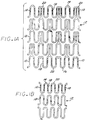
- FIGURE 1A illustrates a partial view of a stent embodying radiopaque markers.
- FIG. 1B illustrates a partial view of another stent embodying radiopaque markers.
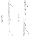
- FIG. 2A illustrates a schematic view of a stent embodying radiopaque markers.
- FIG. 2B illustrates a schematic view of another stent embodiment having radiopaque markers.
- FIG. 3A illustrates a perspective view of a mandrel having annular recesses.
- FIG. 3B illustrates a perspective view of a mandrel without annular recesses.
- FIG. 4A illustrates a partial cross-sectional view of a masked stent loaded upon a mandrel having annular recesses.
- FIG. 4B illustrates a partial cross-sectional view of a masked stent loaded upon a mandrel without annular recesses.
- FIG. 5 illustrates a schematic view of the stent having two rows of radiopaque material along the longitudinal axis in addition to the radiopaque material on either end of the stent.
- radiopaque marker 10 As is shown in the drawings, which are included for purposes of illustration and not by way of limitation, there is provided a radiopaque marker 10 (FIGS. 1 and 2).
- Conventional radiopaque markers are limited in that they may comprise undesirable projections extending from a stent, may be arduous to attach, restrict the expansion capabilities of an expandable stent and may be ineffective in the identification of the position, orientation and configuration of a stent.
- the illustrated radiopaque marker 10 defines an acceptable, very low, profile, conveniently may be affixed to a stent, does not impede the expansion capabilities of an expandable stent, and may be useful in identifying the position, orientation and configuration of a stent within a blood vessel.
- the illustrated radiopaque marker therefore, provides superior means of marking a stent.
- radiopaque marker 10 facilitates precise placement of a stent 12 by way of its novel configuration, position upon a stent, and material properties.
- the characteristics of a radiopaque marker 10 are selected to assure that a stent 12 embodying the radiopaque marker 10 may benefit from the advantages which the invention provides.
- radiopaque marker 10 may have various geometric shapes, comprise various materials and may be positioned anywhere on a stent 12, so long as the desired advantages of the invention are achieved.
- radiopaque marker 10 is plated upon an outer circumference of a generally cylindrical stent 12 and upon a proximal end 14 and a distal end 16 of the stent 12. In another embodiment, it is contemplated that an inner circumference underlying the outer circumference be plated as well. By utilizing plating as the means for affixing radiopaque marker 10 to a stent 12, a minimum profile may be achieved. It is contemplated that the thickness of radiopaque marker 10 be in the range of about 0.008 to 0.080 mm (.0003 to .003 inches) . As such, the radiopaque marker 10 does not appreciably alter the profile of stent 12 and therefore, does not result in stent 12 having substantial projections extending into the blood flow or into the walls of the blood vessel being repaired.
- radiopaque markers 10 easily and accurately can be affixed to a stent. That is, plating is an improved means of affixing radiopaque material to stent 12 over conventional means of affixing radiopaque markers, such as sewing or bonding, which can be tedious and imprecise.
- the preferred embodiment contemplates that the entire circumference of the stent be plated at both its proximal end 14 and distal end 16. It is also contemplated that the plating material may be gold or a material, such as platinum, which has similar radiopaque characteristics .
- radiopaque marker material is contemplated as the preferred radiopaque marker material.
- Other metals suitable as radiopaque markers include, for example, platinum and silver.
- the stent may be effectively identified under fluoroscopy.
- the radiopaque material employed glows so brightly under fluoroscopy so as to obscure the lesion being repaired.
- the images of radiopaque markers comprised of gold or platinum do not, under fluoroscopy, substantially obscure the lesion being repaired.
- the preferred embodiment contemplates affixing radiopaque markers 10 to the ends of stents 12 having various geometric configurations (see FIGS. 2A and 2B).
- the orientation or configuration of the stent 12 irrespective of its geometric configuration, can be ascertained, which is particularly important to the determination of whether a stent has completely repaired a blood vessel.
- the length of the stent 12 can be ascertained and compared to an expected stent length.
- the extent of expansion of an expandable stent 12 can be ascertained and compared with expected values.
- radiopaque markers 10 may be affixed to straight segments 18 of the proximal end 14 and distal end 16 of a stent.
- the curved portions 20 of the stent 12 may deform so as to allow the stent 12 to expand, while the straight portions 18 may remain undeformed.
- a mandrel 30 may be employed (see FIG. 3A) .
- the mandrel 30 may comprise any suitable material formed into an elongate cylindrical shape having a main portion 21 with a cross-sectional diameter sized for receiving stent 12.
- the mandrel may further embody a collar 22 formed or attached to one end of the mandrel 30 that has a cross-sectional diameter larger than that of stent 12 and two annular recesses 23 formed in the main portion 21 which have cross-sectional diameters less than that of the main portion 21.
- the collar 22 functions as a stop and may aid in registering stent 12 upon the mandrel 30.
- Annular recesses 23 function to allow interior surfaces of stent 12 to be plated.
- recesses 23 may be sufficiently shallow or be missing entirely from mandrel 30 so that, where desirable, interior surfaces of stent 12 are not plated with radiopaque material.
- stent 12 is placed upon mandrel 30 and heat shrink tubing 32 (see FIGS. 4A and 4B) is slipped over stent 12.
- the heat shrink tubing 32 is then exposed to heat to shrink the tubing on the stent 12. It is contemplated that the heat be concentrated at a midpoint of the heat shrink tubing 32 and then gradually apply heat towards each end so as to prevent distortion of the stent.
- the shrink tubing 32 may be any polyester having heat shrink properties and the ability to mask the stent during the electroplating process.
- the stent may be precisely positioned on the mandrel 30 and then temporarily secured in place using a high temperature wax.
- the annular recesses 23 may be aligned with the interior portions of the stent 12 desired to be plated (see FIG. 4A). Where it is deemed undesirable to plate the interior surface, no such further alignment is necessary (see FIG. 4B).
- the curved portions 20 (Fig. 1B) of stent 12 as well as the ends of the mandrel 30 can be dipped in high temperature wax to prevent them from being plated.
- the heat shrink tubing 32 surrounding portions of the stent 12 to be plated may be cut away using a standard CO2 laser or its equivalent.
- the laser output is to be limited so that stent 12 and mandrel 30 are not affected.
- portions of the heat shrink tubing 32 may be lased away so that only the outer circumferences of stent 12 may be plated.
- portions of the heat shrink tubing 32 overlaying annular recesses 23 may be lased away, thereby resulting in a stent 12 having desired portions of its interior as well as its exterior plated with radiopaque material (see FIG. 2B).
- an electrical current is used in the process of putting a metallic coating on a metal or other conducting surface.
- a gold solution exists in the form of positively charged ions that have lost one or more electrons.
- the stent is connected to the cathode or negative terminal and the anode, or positive electric terminal, is connected to the stainless steel mandrel 30 which is dipped into the gold solution.
- the ions are attracted to the cathode and the coating is deposited on the stent metal surface.
- the thickness of the layer deposited depends on the amperage of the electric current, the concentration of the metallic ions and the length of time that the stent is plated.
- the plating process should be at a low enough amperage to prevent mapping, nodules, or a matte surface.
- the wax is removed from stent 12 and mandrel 30 by inserting the two elements into acetone or an equivalent solution.
- the stent 12 is plated with a radiopaque marker 10, it is removed from the mandrel 30 and the heat shrink tubing 24 is stripped away.
- the heat shrink tubing 24 may be removed, for example, by cutting it with a laser or in the alternative, dissolved with chemicals.
- the mandrel 30 is withdrawn from the plated stent 12 and the stent 12 may be cleaned with an alcohol-containing solution such as "Alcomox,” or equivalent solution.
- the entire exterior surface of a stent may be plated with radiopaque material. Subsequent to plating, the stent 12 is masked and subjected to etching. In this embodiment, the areas designated to retain radiopaque material are masked and the radiopaque material is etched away from the remaining portions of the stent.
- radiopaque markers having some pattern are affixed to a generally cylindrical stent so as to facilitate the identification, position and configuration of a stent 12 within a blood vessel.
- the pattern of a radiopaque marker 10 may be in the form of a sine wave. As the sine wave expands along with the stent during deployment, it is visible under fluoroscopy and it can be determined whether the stent 12 is properly seated within a blood vessel by viewing the amplitude and shape of the sine wave radiopaque marker.
- the pattern 13 of a radiopaque marker 10 may be a continuous or dashed line extending from the proximal end 14 to the distal end 16 of stent 12. A longitudinal marker of the type described will allow the doctor to determine if the stent has twisted upon deployment or if it expanded unevenly.
- a radiopaque plastic may be coated or affixed to all or a portion of a stent.
- a radiopaque plastic is formed by loading a plastic material with a radiopaque material such as barium sulfate or bismute trioxide. The resultant mixture is then coated or affixed to the stent.
- Several methods of affixing the radiopaque material to the stent include: (1) melting the radiopaque material and then dipping the stent into the melt; (2) solvent casting; and (3) vacuum deposition. These methods are known generally and various process steps are apparent to those skilled in the art. As with the plating process steps described above, the stent can be masked and mounted on a mandrel and then coated, by dipping, solvent casting, or vacuum deposition.
- the radiopaque marker described effectively identifies the location and configuration of a stent within a patient's body lumen of a patient and provides a method and apparatus for constructing the same.
Abstract
Description
- This invention relates to endoprosthesis devices, generally called stents, and, more particularly, radiopaque markers for use with endoprosthesis devices.
- Stents are useful in the treatment of atherosclerotic stenoses in blood vessels and are generally tubular shaped devices which function to hold open a segment of a blood vessel or other anatomical lumen. They are particularly suitable for use in supporting and holding back a dissected arterial lining which can occlude the fluid passage way therethrough.
- In order to accomplish precise placement of stents, various means are employed to identify the position of the stent within a blood vessel. One means frequently described for accomplishing precise placement of a stent is the attachment of radiopaque markers to the stent so that through the use of fluoroscopy, the position of the stent within a blood vessel can be identified. Once the stent with its radiopaque markers has been implanted, subsequent checkups of the treated segment are easily performed since the markers remain visible under fluoroscopy.
- Conventional radiopaque markers, however, have various limitations. Upon attachment to a stent, certain conventional radiopaque markers define a profile that is readily discernible from that of the stent, thereby comprising projections which may undesirably alter the contemplated profile of the stent. That is, these conventional radiopaque markers protrude from the walls of the stent and depending upon their location upon the stent, may either project into the blood flow or into the walls of the blood vessel. In addition, these conventional radiopaque markers are limited in that their attachment to the stent can be tedious and imprecise.
- Other conventional radiopaque markers restrict the expansion capabilities of an expandable stent by adding rigidity to the stent in areas designated for stent deformation. Still other conventional stents utilize material, such as tantalum, that is effective for use in identifying the location of a stent within a vessel, but fluoroscopically illuminate so brightly so as to obscure proper visibility of the blood vessel lesion, thereby impairing the ability to repair the lesion. Finally, conventional radiopaque markers do not generally, under fluoroscopy, provide the operator with means to accurately assess stent length and diameter.
- To overcome the problems and limitations associated with stents having conventional radiopaque markers, it would be desirable to employ radiopaque markers that can be consistently and precisely attached to a stent, that do not limit the expansion capabilities of an expandable stent, that define an acceptable profile, that provide means to assess stent length and diameter and that do not obscure the blood vessel lesion being repaired.
- Particular embodiments of the invention provide a radiopaque marker that may be consistently and precisely affixed to a stent, that does not limit the expansion capabilities of an expandable stent, that has an acceptable profile and that may effectively identify the position, diameter and length of a stent within a blood vessel without obscuring a lesion being repaired. Certain embodiments also provide means for affixing to a stent a radiopaque marker having the aforementioned characteristics.
- A radiopaque marker embodying the invention may be utilized with stents having various geometric shapes and materials. In addition, the radiopaque marker may be positioned anywhere on a stent and may comprise any plateable radiopaque material having various patterns. Further, any acceptable means for affixing the radiopaque marker to a stent may be employed. It is preferable, however, that the means for attaching a radiopaque marker, its location upon a stent as well as the material and geometric shape of the stent, be selected so that a stent incorporating the radiopaque marker embodying the invention may benefit from the advantages provided thereby.
- In a preferred embodiment, the radiopaque markers of the present invention are affixed to both a distal and a proximal end of a generally cylindrical stent. In this embodiment, the radiopaque marker material is gold and is affixed to the outside circumference of a generally cylindrical stent by means of plating. Although gold is the designated material of this embodiment, other biocompatible plateable radiopaque materials, such as platinum, are equally desirable. Plating is preferable since it can be performed easily and with accuracy and can be utilized to produce an acceptable radiopaque marker profile. It is contemplated that the thickness of the radiopaque marker material upon a stent be in the range of about 0.008 to 0.080 mm (.0003 to .003 inches) on the exterior surface of the stent, and if required for fluoroscopic illumination, the same thickness can be plated to the inner stent surface. It is also contemplated that the stent may comprise any material, for example any metal or plastic, upon which gold may be plated.
- Although radiopaque material may be plated on only a portion of the circumference of the stent, in a preferred embodiment it is contemplated that the entire circumference of the stent be plated, thereby producing a stent with a band of radiopaque material at its distal and proximal ends. Moreover, it is significant that only the ends of the stent are plated and that gold, or a similarly effective material, may be selected as the plating material. Plating provides controlled deposition of the radiopaque material on the stent thereby controlling its fluoroscopic illumination. By plating only the two ends of the stent, the fluoroscopic illumination is thus limited to the ends of the stent. These two features minimize the possibility of obscuring the fluoroscopic visualization of the blood vessel being treated.
- In addition, by plating with radiopaque material at both ends and upon the outside of a generally cylindrical stent, not only can the location of the stent be determined under fluoroscopy, but the length and diameter of the device can be determined as well. This is particularly useful where the subject stent is expandable, since the degree of expansion can be ascertained by noting the height of each radiopaque marker and the relative distances between the radiopaque markers. Further, it can be determined under fluoroscopy whether or not the stent is twisted or otherwise improperly seated within a blood vessel.
- In order to successfully plate gold, or any acceptable radiopaque marker material upon a stent, the stent is placed upon a mandrel, then is masked and plated. In a preferred procedure, the stent is placed upon an elongated cylindrical mandrel, masked with shrink tubing, portions of which are lased away to expose the areas of the stent desired to be plated and, thereafter, plated with the desired radiopaque material. It is contemplated that the mandrel may comprise annular recesses which function to allow portions of an interior circumference of a stent, as well as the exterior of that stent, to be plated.
- Subsequent to the completion of the plating procedure, in a preferred procedure the shrink tubing is detached from the stent and the stent is removed from the mandrel. It is contemplated that the shrink tubing may be cut from the stent utilizing a laser. Alternatively, the shrink tubing may be dissolved with chemicals. It also is contemplated that the shrink tubing be pre-fabricated or cut to size (by means of a laser) to precise dimensions, so that the tubing properly can perform its masking function.
- Since a preferred embodiment contemplates gold plating as the avenue for affixing radiopaque markers to a stent, and since gold plating may stiffen a stent in the areas of plating, it is contemplated that expandable stents may be plated in areas where additional rigidity does not affect the expansion capabilities of the stent. Thus, portions of a stent that do not deform upon expansion are plated with gold or the desired radiopaque material. In this way, the stent can freely and uniformly expand and elastically deform without additional restrictions, thereby accomplishing its expansion function while still benefitting from the advantages of the present invention.
- In another embodiment, the entire exterior surface of a stent is plated with radiopaque material. Thereafter, the portions designated to retain radiopaque material are masked and the radiopaque material is etched away from the remaining portions of the stent.
- In yet another embodiment, a generally cylindrical stent is fitted with radiopaque markers having some geometrical configuration or placed upon a stent in some pattern. For instance, a radiopaque marker may comprise a sine wave pattern so that under fluoroscopy, the configuration of the stent may be quickly ascertained. That is, it can be readily ascertained whether the stent is improperly twisted or contorted and, in the case of an expandable stent, whether the stent properly has been deformed.
- Other features and advantages of the present invention will become apparent from the following detailed description, taken in conjunction with the accompanying drawings, which illustrate, by way of example, the principles of the invention.
- FIGURE 1A illustrates a partial view of a stent embodying radiopaque markers.
- FIG. 1B illustrates a partial view of another stent embodying radiopaque markers.
- FIG. 2A illustrates a schematic view of a stent embodying radiopaque markers.
- FIG. 2B illustrates a schematic view of another stent embodiment having radiopaque markers.
- FIG. 3A illustrates a perspective view of a mandrel having annular recesses.
- FIG. 3B illustrates a perspective view of a mandrel without annular recesses.
- FIG. 4A illustrates a partial cross-sectional view of a masked stent loaded upon a mandrel having annular recesses.
- FIG. 4B illustrates a partial cross-sectional view of a masked stent loaded upon a mandrel without annular recesses.
- FIG. 5 illustrates a schematic view of the stent having two rows of radiopaque material along the longitudinal axis in addition to the radiopaque material on either end of the stent.
- As is shown in the drawings, which are included for purposes of illustration and not by way of limitation, there is provided a radiopaque marker 10 (FIGS. 1 and 2). Conventional radiopaque markers are limited in that they may comprise undesirable projections extending from a stent, may be arduous to attach, restrict the expansion capabilities of an expandable stent and may be ineffective in the identification of the position, orientation and configuration of a stent. The illustrated
radiopaque marker 10 defines an acceptable, very low, profile, conveniently may be affixed to a stent, does not impede the expansion capabilities of an expandable stent, and may be useful in identifying the position, orientation and configuration of a stent within a blood vessel. The illustrated radiopaque marker therefore, provides superior means of marking a stent. - The illustrated marker facilitates precise placement of a
stent 12 by way of its novel configuration, position upon a stent, and material properties. The characteristics of aradiopaque marker 10 are selected to assure that astent 12 embodying theradiopaque marker 10 may benefit from the advantages which the invention provides. Thus,radiopaque marker 10 may have various geometric shapes, comprise various materials and may be positioned anywhere on astent 12, so long as the desired advantages of the invention are achieved. - In a preferred embodiment,
radiopaque marker 10 is plated upon an outer circumference of a generallycylindrical stent 12 and upon aproximal end 14 and adistal end 16 of thestent 12. In another embodiment, it is contemplated that an inner circumference underlying the outer circumference be plated as well. By utilizing plating as the means for affixingradiopaque marker 10 to astent 12, a minimum profile may be achieved. It is contemplated that the thickness ofradiopaque marker 10 be in the range of about 0.008 to 0.080 mm (.0003 to .003 inches) . As such, theradiopaque marker 10 does not appreciably alter the profile ofstent 12 and therefore, does not result instent 12 having substantial projections extending into the blood flow or into the walls of the blood vessel being repaired. - In addition, by plating or similarly affixing radiopaque material upon a stent,
radiopaque markers 10 easily and accurately can be affixed to a stent. That is, plating is an improved means of affixing radiopaque material tostent 12 over conventional means of affixing radiopaque markers, such as sewing or bonding, which can be tedious and imprecise. - Although it is not necessary for all embodiments, the preferred embodiment contemplates that the entire circumference of the stent be plated at both its
proximal end 14 anddistal end 16. It is also contemplated that the plating material may be gold or a material, such as platinum, which has similar radiopaque characteristics . - It is significant that gold, or a similar material, is contemplated as the preferred radiopaque marker material. Other metals suitable as radiopaque markers include, for example, platinum and silver. By selecting such a material, the stent may be effectively identified under fluoroscopy. In various conventional stents, the radiopaque material employed glows so brightly under fluoroscopy so as to obscure the lesion being repaired. In contrast, the images of radiopaque markers comprised of gold or platinum do not, under fluoroscopy, substantially obscure the lesion being repaired.
- It is also significant that the preferred embodiment contemplates affixing
radiopaque markers 10 to the ends ofstents 12 having various geometric configurations (see FIGS. 2A and 2B). By doing so, the orientation or configuration of thestent 12, irrespective of its geometric configuration, can be ascertained, which is particularly important to the determination of whether a stent has completely repaired a blood vessel. By noting the distance between the radiopaque bands, the length of thestent 12 can be ascertained and compared to an expected stent length. By observing the height or width of theradiopaque markers 10, the extent of expansion of anexpandable stent 12 can be ascertained and compared with expected values. Similarly, by examining the radiopaque markers embodying the invention under fluoroscopy, it can be determined whether thestent 12 is twisted or otherwise improperly is seated within a vessel. - The plating of radiopaque markers upon a stent may add some rigidity to a stent in the areas of plating. Since this is the case, the preferred embodiment contemplates affixing
radiopaque markers 10 to only those portions of anexpandable stent 12 that do not deform upon expansion. As shown in FIGS. 1a and 1b for example,radiopaque markers 10 may be affixed tostraight segments 18 of theproximal end 14 anddistal end 16 of a stent. Upon expansion, thecurved portions 20 of thestent 12 may deform so as to allow thestent 12 to expand, while thestraight portions 18 may remain undeformed. By affixingradiopaque markers 10 to thestraight portions 18 ofstent 12 as shown in FIGS. 1A and 1B, the additional rigidity added to thestent 12 by theradiopaque markers 10 does not impede expansion. Therefore, an expandable stent havingradiopaque markers 10 embodying the invention can expand uniformly and predictably. - In order to plate a
radiopaque marker 10 upon astent 12, amandrel 30 may be employed (see FIG. 3A) . Themandrel 30 may comprise any suitable material formed into an elongate cylindrical shape having amain portion 21 with a cross-sectional diameter sized for receivingstent 12. The mandrel may further embody acollar 22 formed or attached to one end of themandrel 30 that has a cross-sectional diameter larger than that ofstent 12 and twoannular recesses 23 formed in themain portion 21 which have cross-sectional diameters less than that of themain portion 21. Thecollar 22 functions as a stop and may aid in registeringstent 12 upon themandrel 30.Annular recesses 23 function to allow interior surfaces ofstent 12 to be plated. In another embodiment of mandrel 30 (FIG. 3B), recesses 23 may be sufficiently shallow or be missing entirely frommandrel 30 so that, where desirable, interior surfaces ofstent 12 are not plated with radiopaque material. - In a preferred method,
stent 12 is placed uponmandrel 30 and heat shrink tubing 32 (see FIGS. 4A and 4B) is slipped overstent 12. The heat shrinktubing 32 is then exposed to heat to shrink the tubing on thestent 12. It is contemplated that the heat be concentrated at a midpoint of the heat shrinktubing 32 and then gradually apply heat towards each end so as to prevent distortion of the stent. Theshrink tubing 32 may be any polyester having heat shrink properties and the ability to mask the stent during the electroplating process. - Once the heat shrink
tubing 32 is snug uponstent 12, the stent may be precisely positioned on themandrel 30 and then temporarily secured in place using a high temperature wax. Where it is desired to plate an interior as well as an exterior surface ofstent 12, theannular recesses 23 may be aligned with the interior portions of thestent 12 desired to be plated (see FIG. 4A). Where it is deemed undesirable to plate the interior surface, no such further alignment is necessary (see FIG. 4B). Next, the curved portions 20 (Fig. 1B) ofstent 12 as well as the ends of themandrel 30 can be dipped in high temperature wax to prevent them from being plated. - In order to plate the desired portions of
stent 12, the heat shrinktubing 32 surrounding portions of thestent 12 to be plated may be cut away using a standard CO₂ laser or its equivalent. The laser output is to be limited so thatstent 12 andmandrel 30 are not affected. By utilizing amandrel 30 without annular recesses (see FIGS. 3B and 4B), portions of the heat shrinktubing 32 may be lased away so that only the outer circumferences ofstent 12 may be plated. By employing themandrel 30 illustrated in FIGS. 3A and 4A, portions of the heat shrinktubing 32 overlayingannular recesses 23 may be lased away, thereby resulting in astent 12 having desired portions of its interior as well as its exterior plated with radiopaque material (see FIG. 2B). - As with any electroplating process, an electrical current is used in the process of putting a metallic coating on a metal or other conducting surface. In the preferred embodiment, a gold solution exists in the form of positively charged ions that have lost one or more electrons. The stent is connected to the cathode or negative terminal and the anode, or positive electric terminal, is connected to the
stainless steel mandrel 30 which is dipped into the gold solution. The ions are attracted to the cathode and the coating is deposited on the stent metal surface. As is known in the art, the thickness of the layer deposited depends on the amperage of the electric current, the concentration of the metallic ions and the length of time that the stent is plated. The plating process should be at a low enough amperage to prevent mapping, nodules, or a matte surface. - After plating the gold on the stent, the wax is removed from
stent 12 andmandrel 30 by inserting the two elements into acetone or an equivalent solution. - As can be appreciated from the drawings (FIGS. 2A and 2B), the
end portions stent 12 which are not masked, are plated with radiopaque material and the portions of thestent 12 which are masked, are not plated. - Once the
stent 12 is plated with aradiopaque marker 10, it is removed from themandrel 30 and the heat shrink tubing 24 is stripped away. The heat shrink tubing 24 may be removed, for example, by cutting it with a laser or in the alternative, dissolved with chemicals. Finally, themandrel 30 is withdrawn from the platedstent 12 and thestent 12 may be cleaned with an alcohol-containing solution such as "Alcomox," or equivalent solution. - In another embodiment, the entire exterior surface of a stent may be plated with radiopaque material. Subsequent to plating, the
stent 12 is masked and subjected to etching. In this embodiment, the areas designated to retain radiopaque material are masked and the radiopaque material is etched away from the remaining portions of the stent. - In yet another embodiment, radiopaque markers having some pattern are affixed to a generally cylindrical stent so as to facilitate the identification, position and configuration of a
stent 12 within a blood vessel. For example, the pattern of aradiopaque marker 10 may be in the form of a sine wave. As the sine wave expands along with the stent during deployment, it is visible under fluoroscopy and it can be determined whether thestent 12 is properly seated within a blood vessel by viewing the amplitude and shape of the sine wave radiopaque marker. As another example, as depicted in Fig. 5, thepattern 13 of aradiopaque marker 10 may be a continuous or dashed line extending from theproximal end 14 to thedistal end 16 ofstent 12. A longitudinal marker of the type described will allow the doctor to determine if the stent has twisted upon deployment or if it expanded unevenly. - In an alternative embodiment, a radiopaque plastic may be coated or affixed to all or a portion of a stent. In this embodiment, a radiopaque plastic is formed by loading a plastic material with a radiopaque material such as barium sulfate or bismute trioxide. The resultant mixture is then coated or affixed to the stent. Several methods of affixing the radiopaque material to the stent are contemplated and include: (1) melting the radiopaque material and then dipping the stent into the melt; (2) solvent casting; and (3) vacuum deposition. These methods are known generally and various process steps are apparent to those skilled in the art. As with the plating process steps described above, the stent can be masked and mounted on a mandrel and then coated, by dipping, solvent casting, or vacuum deposition.
- From the foregoing it will be appreciated that the radiopaque marker described effectively identifies the location and configuration of a stent within a patient's body lumen of a patient and provides a method and apparatus for constructing the same.
- While several particular forms of the invention have been illustrated and described, it will also be apparent that various modifications can be made without departing from the scope of the invention. Thus, it should be understood that various changes in form, and detail, and application of the present invention may be made without departing from the scope of this invention.
Claims (31)
- A radiopaque marker (10), comprising: a band of radiopaque material affixed by means of plating to at least a portion of an outer circumference of a generally cylindrical stent (12).
- The radiopaque marker (10) of claim 1, wherein said radiopaque marker is affixed adjacent a proximal end (14) and a distal end (16) of the generally cylindrical stent (12).
- The radiopaque marker (10) of claim 1, or claim 2 wherein said stent (12) is expandable and comprises a deforming portion (20) and a non-deforming portion (18), the radiopaque marker being affixed to said non-deforming portion (18).
- The radiopaque marker (10) of any preceding claim, wherein said radiopaque material comprises a metal taken from the group of gold, platinum and silver.
- The radiopaque marker (10) of any preceding claim, wherein said band of radiopaque material has a thickness in the range of approximately 0.008 to 0.080 mm (.0003 to .003 inches).
- The radiopaque marker (10) of any preceding claim, wherein said band extends a full circumference of a portion of said stent (12).
- The radiopaque marker of any preceding claim, wherein said band comprises a pattern (13).
- The radiopaque marker (10) of claim 7, wherein said pattern (13) comprises a wave-like shape.
- A medical device for implantation in a blood vessel or artery, comprising:
an intravascular stent (12) having a generally cylindrical configuration; and
a radiopaque material (10) affixed to a portion of said intravascular stent so that said radiopaque material (10) is visible under fluoroscopy and can be easily located in the blood vessel or artery where said stent (12) is being implanted. - The medical device of claim 9, wherein said intravascular stent (12) has a proximal end (14) and a distal end (16) and said radiopaque material (10) is coated adjacent said proximal end (14) and said distal end (16).
- The medical device of claim 9, or claim 10 wherein said stent (12) is expandable and comprises a deforming portion (20) and a non-deforming portion (18), and said radiopaque material (10) is affixed to said non-deforming portion (18).
- The medical device of any of claims 9 to 11, wherein said radiopaque material (10) comprises a metal taken from the group of metals consisting of gold, platinum and silver.
- The medical device of any of claims 9 to 12, wherein said radiopaque material (10) has a thickness in the range of approximately 0.008 to 0.080 mm (.0003 to .003 inches).
- The medical device of any of claims 9 to 13, wherein said radiopaque material (10) extends a full circumference of a portion of said stent (12).
- The medical device of any of claims 9 to 14, wherein said radiopaque material comprises a pattern (13).
- The medical device of claim 15, wherein said pattern of said radiopaque material comprises a wave-like shape.
- A method for affixing a radiopaque marker to a generally cylindrical stent (12) comprising the steps:
placing said stent (12) upon a mandrel (30);
attaching masking material (32) to a portion of said stent (12);
coating at least a portion of said stent (12) with a radiopaque material;
removing said masking material (32) from said stent; and
removing said stent (12) from said mandrel (30). - The method of claim 17, wherein said masking material (32) is a heat shrink tubing, which is heated and applied to a portion of said stent (12).
- The method of claim 17 or claim 18, wherein said coating step includes plating a coating of metal on a portion of said stent (12), the metal taken from the group gold, platinum and silver.
- The method of any of claims 17 to 19, wherein said coating step includes coating a radiopaque plastic on a portion of said stent.
- The method of any of claims 17 to 20, wherein said coating step includes dipping said stent (12) in a solution of radiopaque plastic so that said portion of said stent receives said coating of radiopaque plastic.
- The method of any of claims 17 to 21, wherein said coating step includes solvent casting a radiopaque plastic on at least said portion of said stent (12).
- The method of any of claims 17 to 22, wherein said coating step includes vacuum deposition of a radiopaque plastic on at least said portion of said stent (12).
- The method of any of claims 17 to 23, wherein said masking material (32) is pre-fabricated to pre-determined dimensions.
- The method of any of claims 17 to 24, wherein said masking material (32) is cut to desired dimensions once placed upon said stent (12).
- The method of claim 25, wherein said masking material (32) is cut to desired dimensions by use of a laser.
- The method of any of claims 17 to 26, wherein said masking material (32) is removed by using a laser to cut said masking material from said stent (12).
- The method of any of claims 17 to 27, wherein said masking material (32) is removed by dissolving said masking material with chemicals.
- A method for affixing a radiopaque marker (10) to a generally cylindrical stent (12) comprising the steps:
placing said stent upon a mandrel (30);
plating said stent with a radiopaque material;
masking a portion of said stent with a masking material (32);
etching said radiopaque material from an unmasked portion of said stent; and
removing said masking material from said stent. - The method of claim 29, wherein said plating step includes depositing a coating of metal on a portion of said stent, said metal taken from the group gold, platinum and silver.
- The method of claim 29 or claim 30, wherein said plating step includes depositing a coating of a radiopaque material on a portion of said stent (12).
Applications Claiming Priority (2)
| Application Number | Priority Date | Filing Date | Title |
|---|---|---|---|
| US23304694A | 1994-04-25 | 1994-04-25 | |
| US233046 | 1994-04-25 |
Publications (3)
| Publication Number | Publication Date |
|---|---|
| EP0679372A2 true EP0679372A2 (en) | 1995-11-02 |
| EP0679372A3 EP0679372A3 (en) | 1996-01-17 |
| EP0679372B1 EP0679372B1 (en) | 1999-07-28 |
Family
ID=22875665
Family Applications (1)
| Application Number | Title | Priority Date | Filing Date |
|---|---|---|---|
| EP95302708A Revoked EP0679372B1 (en) | 1994-04-25 | 1995-04-24 | Radiopaque stent markers |
Country Status (5)
| Country | Link |
|---|---|
| US (1) | US5725572A (en) |
| EP (1) | EP0679372B1 (en) |
| JP (1) | JP2825452B2 (en) |
| CA (1) | CA2147709C (en) |
| DE (1) | DE69510986T2 (en) |
Cited By (84)
| Publication number | Priority date | Publication date | Assignee | Title |
|---|---|---|---|---|
| DE29607916U1 (en) * | 1996-05-02 | 1996-06-27 | Jomed Implantate Gmbh | Radially expandable stent for implantation within a body vessel |
| WO1997036556A1 (en) * | 1996-03-29 | 1997-10-09 | WILLY RüSCH AG | Stent |
| EP0800800A1 (en) * | 1996-04-10 | 1997-10-15 | Variomed AG | Stent for transluminal implantation in a hollow organ |
| WO1997037616A2 (en) * | 1996-04-05 | 1997-10-16 | Medtronic, Inc. | Endoluminal prostheses having position indicating markers |
| WO1997039699A1 (en) * | 1996-04-24 | 1997-10-30 | Legona Anstalt | Endoprothesis intended to be set in place into a body channel |
| WO1997040783A2 (en) * | 1996-04-26 | 1997-11-06 | Jang G David | Intravascular stent |
| WO1997040780A1 (en) * | 1996-04-26 | 1997-11-06 | Jang G David | Intravascular stent |
| EP0808612A1 (en) * | 1996-04-24 | 1997-11-26 | Legona Anstalt | Endoprosthesis for insertion into a body vessel |
| US5718713A (en) * | 1997-04-10 | 1998-02-17 | Global Therapeutics, Inc. | Surgical stent having a streamlined contour |
| EP0832618A1 (en) | 1996-09-25 | 1998-04-01 | Terumo Kabushiki Kaisha | Stent for dilating a stenotic lesion of a blood vessel |
| US5741327A (en) * | 1997-05-06 | 1998-04-21 | Global Therapeutics, Inc. | Surgical stent featuring radiopaque markers |
| US5746691A (en) * | 1997-06-06 | 1998-05-05 | Global Therapeutics, Inc. | Method for polishing surgical stents |
| EP0839503A1 (en) * | 1996-10-02 | 1998-05-06 | Navius Corporation | Improved stent |
| EP0847733A1 (en) * | 1996-12-10 | 1998-06-17 | BIOTRONIK Mess- und Therapiegeräte GmbH & Co Ingenieurbüro Berlin | Stent |
| WO1998025656A2 (en) | 1996-11-26 | 1998-06-18 | Medtronic, Inc. | System and methods for removing clots from fluid vessels |
| EP0824900A3 (en) * | 1996-08-22 | 1998-09-16 | Advanced Cardiovascular Systems, Inc. | Protective coating for a stent with intermediate radiopaque coating |
| US5810872A (en) * | 1997-03-14 | 1998-09-22 | Kanesaka; Nozomu | Flexible stent |
| WO1998042277A1 (en) * | 1997-03-25 | 1998-10-01 | Jang G David | Intravascular stent |
| WO1998048735A1 (en) * | 1997-04-25 | 1998-11-05 | Jang G David | Intravascular stent |
| WO1998032412A3 (en) * | 1997-01-24 | 1998-11-12 | Scimed Life Systems Inc | Bistable spring construction for a stent and other medical apparatus |
| DE19724230C1 (en) * | 1997-04-30 | 1998-11-26 | Schering Ag | Applying radioactive coating to stent that has been treated with adhesion promoter |
| US5843175A (en) * | 1997-06-13 | 1998-12-01 | Global Therapeutics, Inc. | Enhanced flexibility surgical stent |
| WO1999001088A1 (en) * | 1997-07-04 | 1999-01-14 | Alain Fouere | Flexible and expansible internal vascular prosthesis for surgical use |
| GB2331246A (en) * | 1997-11-13 | 1999-05-19 | Medinol Ltd | Multilayered metal stent |
| US5922021A (en) * | 1996-04-26 | 1999-07-13 | Jang; G. David | Intravascular stent |
| US5922020A (en) * | 1996-08-02 | 1999-07-13 | Localmed, Inc. | Tubular prosthesis having improved expansion and imaging characteristics |
| US5931866A (en) * | 1998-02-24 | 1999-08-03 | Frantzen; John J. | Radially expandable stent featuring accordion stops |
| US5948016A (en) * | 1997-09-25 | 1999-09-07 | Jang; G. David | Intravascular stent with non-parallel slots |
| US5954743A (en) * | 1996-04-26 | 1999-09-21 | Jang; G. David | Intravascular stent |
| US5980564A (en) * | 1997-08-01 | 1999-11-09 | Schneider (Usa) Inc. | Bioabsorbable implantable endoprosthesis with reservoir |
| US6022359A (en) * | 1999-01-13 | 2000-02-08 | Frantzen; John J. | Stent delivery system featuring a flexible balloon |
| US6039756A (en) * | 1996-04-26 | 2000-03-21 | Jang; G. David | Intravascular stent |
| US6042606A (en) * | 1997-09-29 | 2000-03-28 | Cook Incorporated | Radially expandable non-axially contracting surgical stent |
| US6083259A (en) * | 1998-11-16 | 2000-07-04 | Frantzen; John J. | Axially non-contracting flexible radially expandable stent |
| US6123721A (en) * | 1998-02-17 | 2000-09-26 | Jang; G. David | Tubular stent consists of chevron-shape expansion struts and ipsilaterally attached M-frame connectors |
| US6174330B1 (en) | 1997-08-01 | 2001-01-16 | Schneider (Usa) Inc | Bioabsorbable marker having radiopaque constituents |
| US6187034B1 (en) | 1999-01-13 | 2001-02-13 | John J. Frantzen | Segmented stent for flexible stent delivery system |
| DE19951477A1 (en) * | 1999-10-26 | 2001-05-03 | Biotronik Mess & Therapieg | Stent |
| US6231598B1 (en) | 1997-09-24 | 2001-05-15 | Med Institute, Inc. | Radially expandable stent |
| US6235053B1 (en) | 1998-02-02 | 2001-05-22 | G. David Jang | Tubular stent consists of chevron-shape expansion struts and contralaterally attached diagonal connectors |
| US6245103B1 (en) | 1997-08-01 | 2001-06-12 | Schneider (Usa) Inc | Bioabsorbable self-expanding stent |
| US6251135B1 (en) | 1997-08-01 | 2001-06-26 | Schneider (Usa) Inc | Radiopaque marker system and method of use |
| US6331189B1 (en) | 1999-10-18 | 2001-12-18 | Medtronic, Inc. | Flexible medical stent |
| US6334871B1 (en) | 1996-03-13 | 2002-01-01 | Medtronic, Inc. | Radiopaque stent markers |
| US6402777B1 (en) | 1996-03-13 | 2002-06-11 | Medtronic, Inc. | Radiopaque stent markers |
| WO2002022050A3 (en) * | 2000-09-12 | 2002-09-12 | Scimed Life Systems Inc | Selectively etched radiopaque intraluminal device |
| US6464723B1 (en) | 1999-04-22 | 2002-10-15 | Advanced Cardiovascular Systems, Inc. | Radiopaque stents |
| EP1293178A2 (en) * | 2001-09-13 | 2003-03-19 | Cordis Corporation | Stent with angulated struts |
| US6544185B2 (en) | 2000-10-23 | 2003-04-08 | Valentino Montegrande | Ultrasound imaging marker and method of use |
| US6585757B1 (en) | 1999-09-15 | 2003-07-01 | Advanced Cardiovascular Systems, Inc. | Endovascular stent with radiopaque spine |
| US6638300B1 (en) | 1996-12-24 | 2003-10-28 | Cook Incorporated | Radially expandable non-contracting surgical stent |
| US6654629B2 (en) | 2002-01-23 | 2003-11-25 | Valentino Montegrande | Implantable biomarker and method of use |
| US6730116B1 (en) | 1999-04-16 | 2004-05-04 | Medtronic, Inc. | Medical device for intraluminal endovascular stenting |
| US6770088B1 (en) | 1996-04-26 | 2004-08-03 | Scimed Life Systems, Inc. | Intravascular stent |
| DE10342758A1 (en) * | 2003-09-16 | 2005-04-28 | Campus Gmbh & Co Kg | Device for insertion in body organs with marking of the position control |
| US7060093B2 (en) | 2000-10-30 | 2006-06-13 | Advanced Cardiovascular Systems, Inc. | Increased drug-loading and reduced stress drug delivery device |
| US7135038B1 (en) * | 2002-09-30 | 2006-11-14 | Advanced Cardiovascular Systems, Inc. | Drug eluting stent |
| US7635384B2 (en) | 2003-06-25 | 2009-12-22 | Boston Scientific Scimed, Inc. | Varying circumferential spanned connectors in a stent |
| US7699887B2 (en) | 1997-12-18 | 2010-04-20 | Boston Scientific Scimed, Inc. | Stent-graft with bioabsorbable structural support |
| EP1029517B2 (en) † | 1999-01-14 | 2011-06-22 | Medtronic, Inc. | Staggered endoluminal stent |
| US8075609B2 (en) | 1996-03-05 | 2011-12-13 | Evysio Medical Devices Ulc | Expandable stent |
| US8105373B2 (en) | 2002-12-16 | 2012-01-31 | Boston Scientific Scimed, Inc. | Flexible stent with improved axial strength |
| US8353948B2 (en) | 1997-01-24 | 2013-01-15 | Celonova Stent, Inc. | Fracture-resistant helical stent incorporating bistable cells and methods of use |
| US8628565B2 (en) | 2005-04-13 | 2014-01-14 | Abbott Cardiovascular Systems Inc. | Intravascular stent |
| US8663311B2 (en) | 1997-01-24 | 2014-03-04 | Celonova Stent, Inc. | Device comprising biodegradable bistable or multistable cells and methods of use |
| US8696729B2 (en) | 2002-11-01 | 2014-04-15 | Covidien Lp | Implant delivery system with marker interlock |
| CN104755048A (en) * | 2012-11-05 | 2015-07-01 | 维利欧蒙德股份公司 | Stent |
| US9289536B2 (en) | 2013-03-14 | 2016-03-22 | Endologix, Inc. | Method for forming materials in situ within a medical device |
| US9445926B2 (en) | 1996-04-26 | 2016-09-20 | Boston Scientific Scimed, Inc. | Intravascular stent |
| US9730700B2 (en) | 2008-04-25 | 2017-08-15 | Nellix, Inc. | Stent graft delivery system |
| US9737425B2 (en) | 2005-07-07 | 2017-08-22 | Nellix, Inc. | System and methods for endovascular aneurysm treatment |
| US9814612B2 (en) | 2002-09-20 | 2017-11-14 | Nellix, Inc. | Stent-graft with positioning anchor |
| US10022249B2 (en) | 2004-07-22 | 2018-07-17 | Nellix, Inc. | Graft systems having filling structures supported by scaffolds and methods for their use |
| US10117765B2 (en) | 2011-06-14 | 2018-11-06 | W.L. Gore Associates, Inc | Apposition fiber for use in endoluminal deployment of expandable implants |
| US10349946B2 (en) | 2011-04-06 | 2019-07-16 | Endologix, Inc. | Method and system for treating aneurysms |
| US10993803B2 (en) | 2011-04-01 | 2021-05-04 | W. L. Gore & Associates, Inc. | Elastomeric leaflet for prosthetic heart valves |
| US11123174B2 (en) | 2012-03-13 | 2021-09-21 | W. L. Gore & Associates, Inc. | External steerable fiber for use in endoluminal deployment of expandable devices |
| US11129622B2 (en) | 2015-05-14 | 2021-09-28 | W. L. Gore & Associates, Inc. | Devices and methods for occlusion of an atrial appendage |
| US11173023B2 (en) | 2017-10-16 | 2021-11-16 | W. L. Gore & Associates, Inc. | Medical devices and anchors therefor |
| US11324615B2 (en) | 2011-11-14 | 2022-05-10 | W. L. Gore & Associates, Inc. | External steerable fiber for use in endoluminal deployment of expandable devices |
| US11382781B2 (en) | 2011-11-14 | 2022-07-12 | W. L. Gore & Associates, Inc. | External steerable fiber for use in endoluminal deployment of expandable devices |
| US11457925B2 (en) | 2011-09-16 | 2022-10-04 | W. L. Gore & Associates, Inc. | Occlusive devices |
| US11911258B2 (en) | 2013-06-26 | 2024-02-27 | W. L. Gore & Associates, Inc. | Space filling devices |
| US11957608B2 (en) | 2021-02-01 | 2024-04-16 | Nellix, Inc. | Graft systems having filling structures supported by scaffolds and methods for their use |
Families Citing this family (320)
| Publication number | Priority date | Publication date | Assignee | Title |
|---|---|---|---|---|
| DE69434453T2 (en) * | 1993-03-11 | 2006-03-16 | Medinol Ltd. | stent |
| US6165213A (en) | 1994-02-09 | 2000-12-26 | Boston Scientific Technology, Inc. | System and method for assembling an endoluminal prosthesis |
| US5609627A (en) * | 1994-02-09 | 1997-03-11 | Boston Scientific Technology, Inc. | Method for delivering a bifurcated endoluminal prosthesis |
| US6051020A (en) * | 1994-02-09 | 2000-04-18 | Boston Scientific Technology, Inc. | Bifurcated endoluminal prosthesis |
| US5765418A (en) * | 1994-05-16 | 1998-06-16 | Medtronic, Inc. | Method for making an implantable medical device from a refractory metal |
| US6818014B2 (en) * | 1995-03-01 | 2004-11-16 | Scimed Life Systems, Inc. | Longitudinally flexible expandable stent |
| US6981986B1 (en) * | 1995-03-01 | 2006-01-03 | Boston Scientific Scimed, Inc. | Longitudinally flexible expandable stent |
| WO1996026689A1 (en) * | 1995-03-01 | 1996-09-06 | Scimed Life Systems, Inc. | Improved longitudinally flexible expandable stent |
| US7204848B1 (en) | 1995-03-01 | 2007-04-17 | Boston Scientific Scimed, Inc. | Longitudinally flexible expandable stent |
| US20070073384A1 (en) * | 1995-03-01 | 2007-03-29 | Boston Scientific Scimed, Inc. | Longitudinally flexible expandable stent |
| US6602281B1 (en) * | 1995-06-05 | 2003-08-05 | Avantec Vascular Corporation | Radially expansible vessel scaffold having beams and expansion joints |
| CA2223502A1 (en) * | 1995-06-08 | 1996-12-27 | Bard Galway Limited | Bifurcated endovascular stent |
| FR2737969B1 (en) * | 1995-08-24 | 1998-01-30 | Rieu Regis | INTRALUMINAL ENDOPROSTHESIS IN PARTICULAR FOR ANGIOPLASTY |
| US5776161A (en) * | 1995-10-16 | 1998-07-07 | Instent, Inc. | Medical stents, apparatus and method for making same |
| US6287336B1 (en) | 1995-10-16 | 2001-09-11 | Medtronic, Inc. | Variable flexibility stent |
| US7641685B2 (en) * | 1996-05-03 | 2010-01-05 | Medinol Ltd. | System and method for delivering a bifurcated stent |
| UA58485C2 (en) | 1996-05-03 | 2003-08-15 | Медінол Лтд. | Method for manufacture of bifurcated stent (variants) and bifurcated stent (variants) |
| US6251133B1 (en) * | 1996-05-03 | 2001-06-26 | Medinol Ltd. | Bifurcated stent with improved side branch aperture and method of making same |
| US6027528A (en) * | 1996-05-28 | 2000-02-22 | Cordis Corporation | Composite material endoprosthesis |
| US5843163A (en) * | 1996-06-06 | 1998-12-01 | Wall; William H. | Expandable stent having radioactive treatment means |
| US6432127B1 (en) | 1996-10-11 | 2002-08-13 | Transvascular, Inc. | Devices for forming and/or maintaining connections between adjacent anatomical conduits |
| US6315791B1 (en) | 1996-12-03 | 2001-11-13 | Atrium Medical Corporation | Self-expanding prothesis |
| US5863285A (en) * | 1997-01-30 | 1999-01-26 | Cordis Corporation | Balloon catheter with radioactive means |
| US6033433A (en) * | 1997-04-25 | 2000-03-07 | Scimed Life Systems, Inc. | Stent configurations including spirals |
| US6451049B2 (en) * | 1998-04-29 | 2002-09-17 | Sorin Biomedica Cardio, S.P.A. | Stents for angioplasty |
| IT1292295B1 (en) * | 1997-04-29 | 1999-01-29 | Sorin Biomedica Cardio Spa | ANGIOPLASTIC STENT |
| EP0890346A1 (en) * | 1997-06-13 | 1999-01-13 | Gary J. Becker | Expandable intraluminal endoprosthesis |
| EP0884029B1 (en) * | 1997-06-13 | 2004-12-22 | Gary J. Becker | Expandable intraluminal endoprosthesis |
| US20040130599A1 (en) * | 1997-07-15 | 2004-07-08 | Silverbrook Research Pty Ltd | Ink jet printhead with amorphous ceramic chamber |
| US6086611A (en) * | 1997-09-25 | 2000-07-11 | Ave Connaught | Bifurcated stent |
| US6071308A (en) * | 1997-10-01 | 2000-06-06 | Boston Scientific Corporation | Flexible metal wire stent |
| US6617488B1 (en) * | 1997-10-14 | 2003-09-09 | Indicator Technologies, Inc. | Method and apparatus for indicating the conditions in an absorbent article |
| US5980565A (en) * | 1997-10-20 | 1999-11-09 | Iowa-India Investments Company Limited | Sandwich stent |
| US6030333A (en) * | 1997-10-24 | 2000-02-29 | Radiomed Corporation | Implantable radiotherapy device |
| US6309414B1 (en) * | 1997-11-04 | 2001-10-30 | Sorin Biomedica Cardio S.P.A. | Angioplasty stents |
| US6330884B1 (en) * | 1997-11-14 | 2001-12-18 | Transvascular, Inc. | Deformable scaffolding multicellular stent |
| US6168570B1 (en) | 1997-12-05 | 2001-01-02 | Micrus Corporation | Micro-strand cable with enhanced radiopacity |
| US6159165A (en) | 1997-12-05 | 2000-12-12 | Micrus Corporation | Three dimensional spherical micro-coils manufactured from radiopaque nickel-titanium microstrand |
| US6022374A (en) * | 1997-12-16 | 2000-02-08 | Cardiovasc, Inc. | Expandable stent having radiopaque marker and method |
| US6503271B2 (en) * | 1998-01-09 | 2003-01-07 | Cordis Corporation | Intravascular device with improved radiopacity |
| US6048362A (en) * | 1998-01-12 | 2000-04-11 | St. Jude Medical Cardiovascular Group, Inc. | Fluoroscopically-visible flexible graft structures |
| US6132460A (en) * | 1998-03-27 | 2000-10-17 | Intratherapeutics, Inc. | Stent |
| US6132461A (en) * | 1998-03-27 | 2000-10-17 | Intratherapeutics, Inc. | Stent with dual support structure |
| US6558415B2 (en) * | 1998-03-27 | 2003-05-06 | Intratherapeutics, Inc. | Stent |
| US6241762B1 (en) * | 1998-03-30 | 2001-06-05 | Conor Medsystems, Inc. | Expandable medical device with ductile hinges |
| US6264689B1 (en) * | 1998-03-31 | 2001-07-24 | Scimed Life Systems, Incorporated | Low profile medical stent |
| US6520983B1 (en) * | 1998-03-31 | 2003-02-18 | Scimed Life Systems, Inc. | Stent delivery system |
| US6436133B1 (en) * | 1998-04-15 | 2002-08-20 | Joseph G. Furst | Expandable graft |
| US20030040790A1 (en) * | 1998-04-15 | 2003-02-27 | Furst Joseph G. | Stent coating |
| US20020099438A1 (en) * | 1998-04-15 | 2002-07-25 | Furst Joseph G. | Irradiated stent coating |
| CA2326828C (en) * | 1998-05-05 | 2008-07-22 | Scimed Life Systems, Inc. | Stent with smooth ends |
| US6050930A (en) * | 1998-06-02 | 2000-04-18 | Teirstein; Paul S. | Irradiation catheter with expandable source |
| US6387060B1 (en) | 1998-06-17 | 2002-05-14 | Advanced Cardiovascular Systems, Inc. | Composite radiopaque intracorporeal product |
| US6171334B1 (en) | 1998-06-17 | 2001-01-09 | Advanced Cardiovascular Systems, Inc. | Expandable stent and method of use |
| US8070796B2 (en) | 1998-07-27 | 2011-12-06 | Icon Interventional Systems, Inc. | Thrombosis inhibiting graft |
| US7967855B2 (en) * | 1998-07-27 | 2011-06-28 | Icon Interventional Systems, Inc. | Coated medical device |
| US6364902B1 (en) * | 1998-10-05 | 2002-04-02 | Noble-Met, Ltd. | Metal composite tube for biomedical applications |
| US6340368B1 (en) | 1998-10-23 | 2002-01-22 | Medtronic Inc. | Implantable device with radiopaque ends |
| US6475234B1 (en) * | 1998-10-26 | 2002-11-05 | Medinol, Ltd. | Balloon expandable covered stents |
| US6743252B1 (en) * | 1998-12-18 | 2004-06-01 | Cook Incorporated | Cannula stent |
| WO2000035378A1 (en) * | 1998-12-18 | 2000-06-22 | Cook Incorporated | Cannula stent |
| US6234981B1 (en) | 1998-12-30 | 2001-05-22 | Advanced Cardiovascular Systems, Inc. | Vapor deposition coated intracorporeal device |
| US6142975A (en) * | 1998-12-31 | 2000-11-07 | Advanced Cardiovascular Systems, Inc. | Guidewire having braided wire over drawn tube construction |
| US7645242B1 (en) * | 1998-12-31 | 2010-01-12 | Advanced Cardiovascular Systems, Inc. | Composite guidewire with drawn and filled tube construction |
| US7717864B1 (en) | 1998-12-31 | 2010-05-18 | Advanced Cardiovascular Systems, Inc. | Composite guidewire with drawn and filled tube construction |
| US7018401B1 (en) | 1999-02-01 | 2006-03-28 | Board Of Regents, The University Of Texas System | Woven intravascular devices and methods for making the same and apparatus for delivery of the same |
| US6361557B1 (en) | 1999-02-05 | 2002-03-26 | Medtronic Ave, Inc. | Staplebutton radiopaque marker |
| US6620192B1 (en) | 1999-03-16 | 2003-09-16 | Advanced Cardiovascular Systems, Inc. | Multilayer stent |
| US6767418B1 (en) | 1999-04-23 | 2004-07-27 | Terumo Kabushiki Kaisha | Ti-Zr type alloy and medical appliance formed thereof |
| US6569193B1 (en) * | 1999-07-22 | 2003-05-27 | Advanced Cardiovascular Systems, Inc. | Tapered self-expanding stent |
| US20030070676A1 (en) * | 1999-08-05 | 2003-04-17 | Cooper Joel D. | Conduits having distal cage structure for maintaining collateral channels in tissue and related methods |
| US20050060044A1 (en) * | 1999-08-05 | 2005-03-17 | Ed Roschak | Methods and devices for maintaining patency of surgically created channels in a body organ |
| US7815590B2 (en) * | 1999-08-05 | 2010-10-19 | Broncus Technologies, Inc. | Devices for maintaining patency of surgically created channels in tissue |
| US20050137715A1 (en) * | 1999-08-05 | 2005-06-23 | Broncus Technologies, Inc. | Methods and devices for maintaining patency of surgically created channels in a body organ |
| US20070265563A1 (en) * | 2006-05-11 | 2007-11-15 | Heuser Richard R | Device for treating chronic total occlusion |
| US6254631B1 (en) * | 1999-09-23 | 2001-07-03 | Intratherapeutics, Inc. | Stent with enhanced friction |
| US6387123B1 (en) | 1999-10-13 | 2002-05-14 | Advanced Cardiovascular Systems, Inc. | Stent with radiopaque core |
| US8458879B2 (en) | 2001-07-03 | 2013-06-11 | Advanced Bio Prosthetic Surfaces, Ltd., A Wholly Owned Subsidiary Of Palmaz Scientific, Inc. | Method of fabricating an implantable medical device |
| US6379383B1 (en) * | 1999-11-19 | 2002-04-30 | Advanced Bio Prosthetic Surfaces, Ltd. | Endoluminal device exhibiting improved endothelialization and method of manufacture thereof |
| US6537310B1 (en) | 1999-11-19 | 2003-03-25 | Advanced Bio Prosthetic Surfaces, Ltd. | Endoluminal implantable devices and method of making same |
| US6508832B1 (en) | 1999-12-09 | 2003-01-21 | Advanced Cardiovascular Systems, Inc. | Implantable nickel-free stainless steel stents and method of making the same |
| EP1132058A1 (en) | 2000-03-06 | 2001-09-12 | Advanced Laser Applications Holding S.A. | Intravascular prothesis |
| US6290722B1 (en) | 2000-03-13 | 2001-09-18 | Endovascular Technologies, Inc. | Tacky attachment method of covered materials on stents |
| CA2402046A1 (en) * | 2000-03-20 | 2001-09-27 | Boston Scientific Limited | Selective radiopaque plating of a stent |
| US7250058B1 (en) | 2000-03-24 | 2007-07-31 | Abbott Cardiovascular Systems Inc. | Radiopaque intraluminal stent |
| WO2001089421A2 (en) | 2000-05-22 | 2001-11-29 | Orbus Medical Technologies Inc. | Self-expanding stent |
| US6800089B1 (en) | 2000-05-31 | 2004-10-05 | Advanced Cardiovascular Systems, Inc. | Mechanical attachment method of cover materials on stents |
| US6652579B1 (en) | 2000-06-22 | 2003-11-25 | Advanced Cardiovascular Systems, Inc. | Radiopaque stent |
| US6540775B1 (en) * | 2000-06-30 | 2003-04-01 | Cordis Corporation | Ultraflexible open cell stent |
| US6799637B2 (en) | 2000-10-20 | 2004-10-05 | Schlumberger Technology Corporation | Expandable tubing and method |
| US6585762B1 (en) * | 2000-08-10 | 2003-07-01 | Paul Stanish | Arteriovenous grafts and methods of implanting the same |
| CN1468080A (en) * | 2000-08-10 | 2004-01-14 | ���뼼����������˾ | Distally narrowed vascular grafts |
| GB0020491D0 (en) | 2000-08-18 | 2000-10-11 | Angiomed Ag | Stent with attached element and method of making such a stent |
| US6649030B1 (en) | 2000-08-31 | 2003-11-18 | Endovascular Technologies, Inc. | Physical vapor deposition of radiopaque markings on a graft |
| US6699278B2 (en) * | 2000-09-22 | 2004-03-02 | Cordis Corporation | Stent with optimal strength and radiopacity characteristics |
| US6695833B1 (en) * | 2000-09-27 | 2004-02-24 | Nellix, Inc. | Vascular stent-graft apparatus and forming method |
| AU2001294869B2 (en) | 2000-09-29 | 2006-06-15 | Cardinal Health 529, Llc | Coated medical devices |
| US7261735B2 (en) * | 2001-05-07 | 2007-08-28 | Cordis Corporation | Local drug delivery devices and methods for maintaining the drug coatings thereon |
| US6863685B2 (en) * | 2001-03-29 | 2005-03-08 | Cordis Corporation | Radiopacity intraluminal medical device |
| US6492615B1 (en) | 2000-10-12 | 2002-12-10 | Scimed Life Systems, Inc. | Laser polishing of medical devices |
| WO2003061502A1 (en) | 2000-10-26 | 2003-07-31 | Scimed Life Systems, Inc. | Stent having radiopaque markers and method of fabricating the same |
| US6574497B1 (en) | 2000-12-22 | 2003-06-03 | Advanced Cardiovascular Systems, Inc. | MRI medical device markers utilizing fluorine-19 |
| US6569194B1 (en) | 2000-12-28 | 2003-05-27 | Advanced Cardiovascular Systems, Inc. | Thermoelastic and superelastic Ni-Ti-W alloy |
| US6547812B1 (en) | 2000-12-29 | 2003-04-15 | Advanced Cardiovascular Systems, Inc. | Radiation therapy using a radioactive implantable device and a radiosensitizer agent |
| US6641607B1 (en) | 2000-12-29 | 2003-11-04 | Advanced Cardiovascular Systems, Inc. | Double tube stent |
| US6635082B1 (en) | 2000-12-29 | 2003-10-21 | Advanced Cardiovascular Systems Inc. | Radiopaque stent |
| NO335594B1 (en) | 2001-01-16 | 2015-01-12 | Halliburton Energy Serv Inc | Expandable devices and methods thereof |
| US20050288750A1 (en) * | 2003-08-25 | 2005-12-29 | Biophan Technologies, Inc. | Medical device with an electrically conductive anti-antenna member |
| US20070168006A1 (en) * | 2001-02-20 | 2007-07-19 | Biophan Technologies, Inc. | Medical device with an electrically conductive anti-antenna member |
| US20050283214A1 (en) * | 2003-08-25 | 2005-12-22 | Biophan Technologies, Inc. | Medical device with an electrically conductive anti-antenna member |
| US20050283167A1 (en) * | 2003-08-25 | 2005-12-22 | Biophan Technologies, Inc. | Medical device with an electrically conductive anti-antenna member |
| US6829509B1 (en) * | 2001-02-20 | 2004-12-07 | Biophan Technologies, Inc. | Electromagnetic interference immune tissue invasive system |
| US20070168005A1 (en) * | 2001-02-20 | 2007-07-19 | Biophan Technologies, Inc. | Medical device with an electrically conductive anti-antenna member |
| US20070173911A1 (en) * | 2001-02-20 | 2007-07-26 | Biophan Technologies, Inc. | Medical device with an electrically conductive anti-antenna member |
| JP2004524911A (en) * | 2001-03-20 | 2004-08-19 | ジーエムピー カーディアック ケア インコーポレーテッド | Rail stent |
| DE10118944B4 (en) | 2001-04-18 | 2013-01-31 | Merit Medical Systems, Inc. | Removable, essentially cylindrical implants |
| US6712844B2 (en) | 2001-06-06 | 2004-03-30 | Advanced Cardiovascular Systems, Inc. | MRI compatible stent |
| US6673106B2 (en) * | 2001-06-14 | 2004-01-06 | Cordis Neurovascular, Inc. | Intravascular stent device |
| US8197535B2 (en) * | 2001-06-19 | 2012-06-12 | Cordis Corporation | Low profile improved radiopacity intraluminal medical device |
| EP1424960B1 (en) | 2001-07-26 | 2010-04-21 | Merit Medical Systems, Inc. | Removable stent |
| US6926733B2 (en) | 2001-08-02 | 2005-08-09 | Boston Scientific Scimed, Inc. | Method for enhancing sheet or tubing metal stent radiopacity |
| US20040073282A1 (en) * | 2001-08-06 | 2004-04-15 | Paul Stanish | Distally-narrowed vascular grafts and methods of using same for making artery-to-vein and artery-to-artery connections |
| US20060004437A1 (en) | 2001-08-29 | 2006-01-05 | Swaminathan Jayaraman | Structurally variable stents |
| US20060280772A1 (en) * | 2001-09-04 | 2006-12-14 | Broncus Technologies, Inc. | Methods and devices for maintaining surgically created channels in a body organ |
| US20050060041A1 (en) * | 2001-09-04 | 2005-03-17 | Broncus Technologies, Inc. | Methods and devices for maintaining surgically created channels in a body organ |
| US7708712B2 (en) * | 2001-09-04 | 2010-05-04 | Broncus Technologies, Inc. | Methods and devices for maintaining patency of surgically created channels in a body organ |
| US20050137611A1 (en) * | 2001-09-04 | 2005-06-23 | Broncus Technologies, Inc. | Methods and devices for maintaining surgically created channels in a body organ |
| US20030060873A1 (en) * | 2001-09-19 | 2003-03-27 | Nanomedical Technologies, Inc. | Metallic structures incorporating bioactive materials and methods for creating the same |
| US7776379B2 (en) * | 2001-09-19 | 2010-08-17 | Medlogics Device Corporation | Metallic structures incorporating bioactive materials and methods for creating the same |
| US20030060872A1 (en) * | 2001-09-26 | 2003-03-27 | Gary Gomringer | Stent with radiopaque characteristics |
| US8740973B2 (en) * | 2001-10-26 | 2014-06-03 | Icon Medical Corp. | Polymer biodegradable medical device |
| US7445629B2 (en) * | 2002-01-31 | 2008-11-04 | Boston Scientific Scimed, Inc. | Medical device for delivering biologically active material |
| US7326245B2 (en) * | 2002-01-31 | 2008-02-05 | Boston Scientific Scimed, Inc. | Medical device for delivering biologically active material |
| US7291165B2 (en) | 2002-01-31 | 2007-11-06 | Boston Scientific Scimed, Inc. | Medical device for delivering biologically active material |
| US20110306997A9 (en) * | 2002-02-21 | 2011-12-15 | Roschak Edmund J | Devices for creating passages and sensing for blood vessels |
| GB0206061D0 (en) * | 2002-03-14 | 2002-04-24 | Angiomed Ag | Metal structure compatible with MRI imaging, and method of manufacturing such a structure |
| US20030181810A1 (en) * | 2002-03-25 | 2003-09-25 | Murphy Kieran P. | Kit for image guided surgical procedures |
| US9375203B2 (en) | 2002-03-25 | 2016-06-28 | Kieran Murphy Llc | Biopsy needle |
| US20030204248A1 (en) * | 2002-03-25 | 2003-10-30 | Murphy Kieran P. | Device viewable under an imaging beam |
| US7927368B2 (en) * | 2002-03-25 | 2011-04-19 | Kieran Murphy Llc | Device viewable under an imaging beam |
| DE60325035D1 (en) * | 2002-04-02 | 2009-01-15 | Verizon Business Global Llc | REMOTE CONTROL SYSTEM WITH INSTANT COMMUNICATION EXTENSIONS |
| AU2003221744A1 (en) * | 2002-04-19 | 2003-11-03 | Broncus Technologies, Inc. | Devices for maintaining surgically created openings |
| US6645547B1 (en) | 2002-05-02 | 2003-11-11 | Labcoat Ltd. | Stent coating device |
| US7048962B2 (en) * | 2002-05-02 | 2006-05-23 | Labcoat, Ltd. | Stent coating device |
| US7637935B2 (en) * | 2002-05-06 | 2009-12-29 | Abbott Laboratories | Endoprosthesis for controlled contraction and expansion |
| AU2003228890A1 (en) * | 2002-05-08 | 2003-11-11 | Abbott Laboratories | Endoprosthesis having foot extensions |
| US7195648B2 (en) | 2002-05-16 | 2007-03-27 | Cordis Neurovascular, Inc. | Intravascular stent device |
| US20030225448A1 (en) * | 2002-05-28 | 2003-12-04 | Scimed Life Systems, Inc. | Polar radiopaque marker for stent |
| US20040002752A1 (en) * | 2002-06-26 | 2004-01-01 | Scimed Life Systems, Inc. | Sacrificial anode stent system |
| DE10233085B4 (en) * | 2002-07-19 | 2014-02-20 | Dendron Gmbh | Stent with guide wire |
| US8016881B2 (en) | 2002-07-31 | 2011-09-13 | Icon Interventional Systems, Inc. | Sutures and surgical staples for anastamoses, wound closures, and surgical closures |
| EP1389451B1 (en) * | 2002-08-13 | 2006-03-01 | Abbott Laboratories Vascular Enterprises Limited | Stent |
| BR0313489A (en) * | 2002-08-15 | 2005-07-05 | Gmp Cardiac Care Inc | Rail graft device |
| US6945995B2 (en) * | 2002-08-29 | 2005-09-20 | Boston Scientific Scimed, Inc. | Stent overlap point markers |
| US9561123B2 (en) | 2002-08-30 | 2017-02-07 | C.R. Bard, Inc. | Highly flexible stent and method of manufacture |
| US6878162B2 (en) * | 2002-08-30 | 2005-04-12 | Edwards Lifesciences Ag | Helical stent having improved flexibility and expandability |
| US20040044399A1 (en) * | 2002-09-04 | 2004-03-04 | Ventura Joseph A. | Radiopaque links for self-expanding stents |
| US20060100695A1 (en) * | 2002-09-27 | 2006-05-11 | Peacock James C Iii | Implantable stent with modified ends |
| US7300459B2 (en) * | 2002-10-17 | 2007-11-27 | Heuser Richard R | Stent with covering and differential dilation |
| US7959671B2 (en) | 2002-11-05 | 2011-06-14 | Merit Medical Systems, Inc. | Differential covering and coating methods |
| US7637942B2 (en) * | 2002-11-05 | 2009-12-29 | Merit Medical Systems, Inc. | Coated stent with geometry determinated functionality and method of making the same |
| US7527644B2 (en) | 2002-11-05 | 2009-05-05 | Alveolus Inc. | Stent with geometry determinated functionality and method of making the same |
| US7875068B2 (en) | 2002-11-05 | 2011-01-25 | Merit Medical Systems, Inc. | Removable biliary stent |
| WO2004045452A2 (en) * | 2002-11-15 | 2004-06-03 | Gmp/Cardiac Care, Inc. | Rail stent-graft for repairing abdominal aortic aneurysm |
| EP1567221A1 (en) * | 2002-11-15 | 2005-08-31 | GMP Cardiac Care, Inc. | Rail stent |
| US7166088B2 (en) * | 2003-01-27 | 2007-01-23 | Heuser Richard R | Catheter introducer system |
| US7172624B2 (en) * | 2003-02-06 | 2007-02-06 | Boston Scientific Scimed, Inc. | Medical device with magnetic resonance visibility enhancing structure |
| US7264633B2 (en) * | 2003-03-20 | 2007-09-04 | Cordis Corp. | Anvil bridge stent design |
| US7214240B2 (en) * | 2003-03-20 | 2007-05-08 | Cordis Corporation | Split-bridge stent design |
| US7625398B2 (en) * | 2003-05-06 | 2009-12-01 | Abbott Laboratories | Endoprosthesis having foot extensions |
| US7625401B2 (en) * | 2003-05-06 | 2009-12-01 | Abbott Laboratories | Endoprosthesis having foot extensions |
| US8048146B2 (en) * | 2003-05-06 | 2011-11-01 | Abbott Laboratories | Endoprosthesis having foot extensions |
| US20040236409A1 (en) | 2003-05-20 | 2004-11-25 | Pelton Alan R. | Radiopacity intraluminal medical device |
| US8002740B2 (en) * | 2003-07-18 | 2011-08-23 | Broncus Technologies, Inc. | Devices for maintaining patency of surgically created channels in tissue |
| US8308682B2 (en) | 2003-07-18 | 2012-11-13 | Broncus Medical Inc. | Devices for maintaining patency of surgically created channels in tissue |
| US20050050042A1 (en) * | 2003-08-20 | 2005-03-03 | Marvin Elder | Natural language database querying |
| US20050283213A1 (en) * | 2003-08-25 | 2005-12-22 | Biophan Technologies, Inc. | Medical device with an electrically conductive anti-antenna member |
| US20050288752A1 (en) * | 2003-08-25 | 2005-12-29 | Biophan Technologies, Inc. | Medical device with an electrically conductive anti-antenna member |
| US20050288756A1 (en) * | 2003-08-25 | 2005-12-29 | Biophan Technologies, Inc. | Medical device with an electrically conductive anti-antenna member |
| US20050288754A1 (en) * | 2003-08-25 | 2005-12-29 | Biophan Technologies, Inc. | Medical device with an electrically conductive anti-antenna member |
| US8868212B2 (en) * | 2003-08-25 | 2014-10-21 | Medtronic, Inc. | Medical device with an electrically conductive anti-antenna member |
| US20050049688A1 (en) * | 2003-08-25 | 2005-03-03 | Biophan Technologies, Inc. | Electromagnetic radiation transparent device and method of making thereof |
| US7402141B2 (en) * | 2003-08-27 | 2008-07-22 | Heuser Richard R | Catheter guidewire system using concentric wires |
| US7020947B2 (en) * | 2003-09-23 | 2006-04-04 | Fort Wayne Metals Research Products Corporation | Metal wire with filaments for biomedical applications |
| US7175654B2 (en) * | 2003-10-16 | 2007-02-13 | Cordis Corporation | Stent design having stent segments which uncouple upon deployment |
| US20050085897A1 (en) * | 2003-10-17 | 2005-04-21 | Craig Bonsignore | Stent design having independent stent segments which uncouple upon deployment |
| US7208172B2 (en) * | 2003-11-03 | 2007-04-24 | Medlogics Device Corporation | Metallic composite coating for delivery of therapeutic agents from the surface of implantable devices |
| US20050119723A1 (en) * | 2003-11-28 | 2005-06-02 | Medlogics Device Corporation | Medical device with porous surface containing bioerodable bioactive composites and related methods |
| US20060085062A1 (en) * | 2003-11-28 | 2006-04-20 | Medlogics Device Corporation | Implantable stent with endothelialization factor |
| US7641647B2 (en) * | 2003-12-29 | 2010-01-05 | Boston Scientific Scimed, Inc. | Medical device with modified marker band |
| GB0400571D0 (en) * | 2004-01-12 | 2004-02-11 | Angiomed Gmbh & Co | Implant |
| US7243408B2 (en) * | 2004-02-09 | 2007-07-17 | Boston Scientific Scimed, Inc. | Process method for attaching radio opaque markers to shape memory stent |
| US8337545B2 (en) | 2004-02-09 | 2012-12-25 | Cook Medical Technologies Llc | Woven implantable device |
| EP1737391A2 (en) * | 2004-04-13 | 2007-01-03 | Cook Incorporated | Implantable frame with variable compliance |
| US20050273156A1 (en) * | 2004-06-07 | 2005-12-08 | Rober Burgermeister | Biocompatible alloy for implantable medical devices |
| US20050276718A1 (en) * | 2004-06-09 | 2005-12-15 | Robert Burgermeister | Cobalt-nickel-chromium biocompatible alloy for implantable medical devices |
| US20050283226A1 (en) * | 2004-06-18 | 2005-12-22 | Scimed Life Systems, Inc. | Medical devices |
| US7794493B2 (en) | 2004-06-30 | 2010-09-14 | Cordis Corporation | Magnetic resonance imaging compatibility alloy for implantable medical devices |
| US8409167B2 (en) | 2004-07-19 | 2013-04-02 | Broncus Medical Inc | Devices for delivering substances through an extra-anatomic opening created in an airway |
| US20090012429A1 (en) * | 2004-08-25 | 2009-01-08 | Heuser Richard R | Catheter guidewire system using concentric wires |
| US8545418B2 (en) | 2004-08-25 | 2013-10-01 | Richard R. Heuser | Systems and methods for ablation of occlusions within blood vessels |
| US20060060266A1 (en) * | 2004-09-01 | 2006-03-23 | Pst, Llc | Stent and method for manufacturing the stent |
| US7780721B2 (en) * | 2004-09-01 | 2010-08-24 | C. R. Bard, Inc. | Stent and method for manufacturing the stent |
| US7887579B2 (en) * | 2004-09-29 | 2011-02-15 | Merit Medical Systems, Inc. | Active stent |
| US20060096672A1 (en) * | 2004-11-09 | 2006-05-11 | Robert Burgermeister | Quaternary cobalt-nickel-chromium-molybdenum fatigue resistant alloy for intravascular medical devices |
| US20060100692A1 (en) * | 2004-11-09 | 2006-05-11 | Robert Burgermeister | Cobalt-chromium-molybdenum fatigue resistant alloy for intravascular medical devices |
| US7540995B2 (en) | 2005-03-03 | 2009-06-02 | Icon Medical Corp. | Process for forming an improved metal alloy stent |
| US20060201601A1 (en) * | 2005-03-03 | 2006-09-14 | Icon Interventional Systems, Inc. | Flexible markers |
| WO2006110197A2 (en) * | 2005-03-03 | 2006-10-19 | Icon Medical Corp. | Polymer biodegradable medical device |
| US8323333B2 (en) * | 2005-03-03 | 2012-12-04 | Icon Medical Corp. | Fragile structure protective coating |
| US9107899B2 (en) | 2005-03-03 | 2015-08-18 | Icon Medical Corporation | Metal alloys for medical devices |
| JP5335244B2 (en) * | 2005-03-03 | 2013-11-06 | アイコン メディカル コーポレーション | Medical member using improved metal alloy |
| US20060264914A1 (en) * | 2005-03-03 | 2006-11-23 | Icon Medical Corp. | Metal alloys for medical devices |
| US20060292077A1 (en) * | 2005-03-18 | 2006-12-28 | Zhao Jonathon Z | Dendritic and star-shaped contrast agents for medical devices and bioabsorbable radiopaque bulk material and method for producing same |
| US8197534B2 (en) * | 2005-03-31 | 2012-06-12 | Cook Medical Technologies Llc | Valve device with inflatable chamber |
| US20060276882A1 (en) * | 2005-04-11 | 2006-12-07 | Cook Incorporated | Medical device including remodelable material attached to frame |
| JP4917089B2 (en) | 2005-05-09 | 2012-04-18 | アンギオメット ゲゼルシャフト ミット ベシュレンクテル ハフツング ウント コムパニー メディツィンテヒニク コマンデイトゲゼルシャフト | Implant delivery device |
| US7731654B2 (en) * | 2005-05-13 | 2010-06-08 | Merit Medical Systems, Inc. | Delivery device with viewing window and associated method |
| US20070100231A1 (en) * | 2005-05-19 | 2007-05-03 | Biophan Technologies, Inc. | Electromagnetic resonant circuit sleeve for implantable medical device |
| US20060276910A1 (en) * | 2005-06-01 | 2006-12-07 | Jan Weber | Endoprostheses |
| JP4797473B2 (en) * | 2005-07-11 | 2011-10-19 | ニプロ株式会社 | Flexible stent with excellent expandability |
| DE202005012982U1 (en) * | 2005-08-17 | 2005-10-27 | Odu-Steckverbindungssysteme Gmbh & Co. Kg | In line electrical connector has a plug with spring arm formed lugs that latch into holes in socket body to secure |
| US9233012B2 (en) | 2005-09-07 | 2016-01-12 | RBKPark, LLC | Medical stent |
| US7632304B2 (en) * | 2005-09-07 | 2009-12-15 | Rbkpark Llc | Coronary stent |
| US20070150041A1 (en) * | 2005-12-22 | 2007-06-28 | Nellix, Inc. | Methods and systems for aneurysm treatment using filling structures |
| US20070156230A1 (en) | 2006-01-04 | 2007-07-05 | Dugan Stephen R | Stents with radiopaque markers |
| US20070203572A1 (en) * | 2006-01-25 | 2007-08-30 | Heuser Richard R | Catheter system with stent apparatus for connecting adjacent blood vessels |
| US8062321B2 (en) * | 2006-01-25 | 2011-11-22 | Pq Bypass, Inc. | Catheter system for connecting adjacent blood vessels |
| US20070203515A1 (en) * | 2006-01-25 | 2007-08-30 | Heuser Richard R | Catheter system for connecting adjacent blood vessels |
| US7374567B2 (en) | 2006-01-25 | 2008-05-20 | Heuser Richard R | Catheter system for connecting adjacent blood vessels |
| CA2640234C (en) | 2006-02-14 | 2017-01-03 | Angiomed Gmbh & Co. Medizintechnik Kg | Highly flexible stent and method of manufacture |
| GB0609841D0 (en) | 2006-05-17 | 2006-06-28 | Angiomed Ag | Bend-capable tubular prosthesis |
| GB0609911D0 (en) | 2006-05-18 | 2006-06-28 | Angiomed Ag | Bend-capable stent prosthesis |
| US20130325107A1 (en) | 2006-05-26 | 2013-12-05 | Abbott Cardiovascular Systems Inc. | Stents With Radiopaque Markers |
| WO2008008291A2 (en) * | 2006-07-13 | 2008-01-17 | Icon Medical Corp. | Stent |
| DE102006033399B4 (en) * | 2006-07-19 | 2009-04-09 | Jotec Gmbh | Marker system and delivery system for such a marker system |
| GB0616729D0 (en) * | 2006-08-23 | 2006-10-04 | Angiomed Ag | Method of welding a component to a shape memory alloy workpiece |
| GB0616999D0 (en) * | 2006-08-29 | 2006-10-04 | Angiomed Ag | Annular mesh |
| US8500793B2 (en) * | 2006-09-07 | 2013-08-06 | C. R. Bard, Inc. | Helical implant having different ends |
| US7988720B2 (en) | 2006-09-12 | 2011-08-02 | Boston Scientific Scimed, Inc. | Longitudinally flexible expandable stent |
| KR101659197B1 (en) | 2006-10-22 | 2016-09-22 | 이데브 테크놀로지스, 아이엔씨. | Devices and methods for stent advancement |
| KR101297043B1 (en) | 2006-10-22 | 2013-08-14 | 이데브 테크놀로지스, 아이엔씨. | Methods for securing strand ends and the resulting devices |
| GB0622465D0 (en) | 2006-11-10 | 2006-12-20 | Angiomed Ag | Stent |
| US20080128187A1 (en) * | 2006-12-01 | 2008-06-05 | Lucky Power Technology Co., Ltd. | Transportation device adapted with a solar photo module |
| GB0624419D0 (en) * | 2006-12-06 | 2007-01-17 | Angiomed Ag | Stenting ring with marker |
| US8768486B2 (en) * | 2006-12-11 | 2014-07-01 | Medtronic, Inc. | Medical leads with frequency independent magnetic resonance imaging protection |
| US20080166526A1 (en) * | 2007-01-08 | 2008-07-10 | Monk Russell A | Formed panel structure |
| US20080177249A1 (en) * | 2007-01-22 | 2008-07-24 | Heuser Richard R | Catheter introducer system |
| EP2120785B1 (en) | 2007-02-12 | 2021-12-01 | C.R. Bard, Inc. | Highly flexible stent and method of manufacture |
| US8333799B2 (en) * | 2007-02-12 | 2012-12-18 | C. R. Bard, Inc. | Highly flexible stent and method of manufacture |
| GB0703379D0 (en) * | 2007-02-21 | 2007-03-28 | Angiomed Ag | Stent with radiopaque marker |
| US20080234813A1 (en) * | 2007-03-20 | 2008-09-25 | Heuser Richard R | Percutaneous Interventional Cardiology System for Treating Valvular Disease |
| US20080243069A1 (en) * | 2007-04-02 | 2008-10-02 | Medtronic Vascular, Inc. | Self-Crimping Radiopaque marker |
| GB0706499D0 (en) * | 2007-04-03 | 2007-05-09 | Angiomed Ag | Bendable stent |
| US20090005853A1 (en) * | 2007-06-26 | 2009-01-01 | Karim Osman | Integration Of Markers Into Bar Arms |
| GB0717481D0 (en) * | 2007-09-07 | 2007-10-17 | Angiomed Ag | Self-expansible stent with radiopaque markers |
| US9034007B2 (en) * | 2007-09-21 | 2015-05-19 | Insera Therapeutics, Inc. | Distal embolic protection devices with a variable thickness microguidewire and methods for their use |
| US8128677B2 (en) | 2007-12-12 | 2012-03-06 | Intact Vascular LLC | Device and method for tacking plaque to a blood vessel wall |
| US9375327B2 (en) | 2007-12-12 | 2016-06-28 | Intact Vascular, Inc. | Endovascular implant |
| US7896911B2 (en) | 2007-12-12 | 2011-03-01 | Innovasc Llc | Device and method for tacking plaque to blood vessel wall |
| US10166127B2 (en) | 2007-12-12 | 2019-01-01 | Intact Vascular, Inc. | Endoluminal device and method |
| US10022250B2 (en) * | 2007-12-12 | 2018-07-17 | Intact Vascular, Inc. | Deployment device for placement of multiple intraluminal surgical staples |
| US9603730B2 (en) | 2007-12-12 | 2017-03-28 | Intact Vascular, Inc. | Endoluminal device and method |
| US8945199B2 (en) * | 2008-06-04 | 2015-02-03 | Nellix, Inc. | Sealing apparatus and methods of use |
| US8388549B2 (en) * | 2008-12-29 | 2013-03-05 | St. Jude Medical, Atrial Fibrillation Division, Inc. | Anatomical thermal sensing device and method |
| US8858610B2 (en) | 2009-01-19 | 2014-10-14 | W. L. Gore & Associates, Inc. | Forced deployment sequence |
| US20120035702A1 (en) * | 2009-04-24 | 2012-02-09 | Keith Horvath | Stent for valve replacement |
| US8114149B2 (en) * | 2009-10-20 | 2012-02-14 | Svelte Medical Systems, Inc. | Hybrid stent with helical connectors |
| US20110276078A1 (en) | 2009-12-30 | 2011-11-10 | Nellix, Inc. | Filling structure for a graft system and methods of use |
| US8568471B2 (en) | 2010-01-30 | 2013-10-29 | Abbott Cardiovascular Systems Inc. | Crush recoverable polymer scaffolds |
| US8808353B2 (en) | 2010-01-30 | 2014-08-19 | Abbott Cardiovascular Systems Inc. | Crush recoverable polymer scaffolds having a low crossing profile |
| US8398916B2 (en) | 2010-03-04 | 2013-03-19 | Icon Medical Corp. | Method for forming a tubular medical device |
| US8632582B2 (en) | 2010-03-25 | 2014-01-21 | Mayo Foundation For Medical Education And Research | Removable and/or retrievable stents and kits |
| US8920486B2 (en) | 2010-05-18 | 2014-12-30 | RBKPark, LLC | Medical device |
| US9023095B2 (en) | 2010-05-27 | 2015-05-05 | Idev Technologies, Inc. | Stent delivery system with pusher assembly |
| US20120022578A1 (en) * | 2010-07-20 | 2012-01-26 | Cook Medical Technologies Llc | Frame-based vena cava filter |
| US9566147B2 (en) | 2010-11-17 | 2017-02-14 | Abbott Cardiovascular Systems, Inc. | Radiopaque intraluminal stents comprising cobalt-based alloys containing one or more platinum group metals, refractory metals, or combinations thereof |
| US11298251B2 (en) | 2010-11-17 | 2022-04-12 | Abbott Cardiovascular Systems, Inc. | Radiopaque intraluminal stents comprising cobalt-based alloys with primarily single-phase supersaturated tungsten content |
| JP2014508559A (en) | 2010-12-30 | 2014-04-10 | ボストン サイエンティフィック サイムド,インコーポレイテッド | Multi-stage open stent design |
| US8801768B2 (en) | 2011-01-21 | 2014-08-12 | Endologix, Inc. | Graft systems having semi-permeable filling structures and methods for their use |
| US8790388B2 (en) | 2011-03-03 | 2014-07-29 | Boston Scientific Scimed, Inc. | Stent with reduced profile |
| CA2823535A1 (en) | 2011-03-03 | 2012-09-07 | Boston Scientific Scimed, Inc. | Low strain high strength stent |
| US8709034B2 (en) | 2011-05-13 | 2014-04-29 | Broncus Medical Inc. | Methods and devices for diagnosing, monitoring, or treating medical conditions through an opening through an airway wall |
| JP2014521381A (en) | 2011-05-13 | 2014-08-28 | ブロンカス テクノロジーズ, インコーポレイテッド | Methods and devices for tissue ablation |
| US10390977B2 (en) | 2011-06-03 | 2019-08-27 | Intact Vascular, Inc. | Endovascular implant |
| US9724494B2 (en) | 2011-06-29 | 2017-08-08 | Abbott Cardiovascular Systems, Inc. | Guide wire device including a solderable linear elastic nickel-titanium distal end section and methods of preparation therefor |
| US8726483B2 (en) | 2011-07-29 | 2014-05-20 | Abbott Cardiovascular Systems Inc. | Methods for uniform crimping and deployment of a polymer scaffold |
| WO2013078235A1 (en) | 2011-11-23 | 2013-05-30 | Broncus Medical Inc | Methods and devices for diagnosing, monitoring, or treating medical conditions through an opening through an airway wall |
| EP2806826B1 (en) | 2012-01-25 | 2020-01-08 | Intact Vascular, Inc. | Endoluminal device |
| EP3281608B1 (en) | 2012-02-10 | 2020-09-16 | CVDevices, LLC | Medical product comprising a frame and visceral pleura |
| ES2692288T3 (en) | 2012-10-25 | 2018-12-03 | Arterial Remodeling Technologies S.A. | Radiopaque marker for bioresorbable stents |
| AU2014214700B2 (en) | 2013-02-11 | 2018-01-18 | Cook Medical Technologies Llc | Expandable support frame and medical device |
| CA2908948C (en) * | 2013-02-28 | 2019-02-26 | Boston Scientific Scimed, Inc. | Stent with balloon for repair of anastomosis surgery leaks |
| SG11201507173QA (en) | 2013-03-15 | 2015-10-29 | Insera Therapeutics Inc | Vascular treatment devices and methods |
| US8715314B1 (en) | 2013-03-15 | 2014-05-06 | Insera Therapeutics, Inc. | Vascular treatment measurement methods |
| US8715315B1 (en) | 2013-03-15 | 2014-05-06 | Insera Therapeutics, Inc. | Vascular treatment systems |
| US8679150B1 (en) | 2013-03-15 | 2014-03-25 | Insera Therapeutics, Inc. | Shape-set textile structure based mechanical thrombectomy methods |
| WO2014181713A1 (en) | 2013-05-07 | 2014-11-13 | 株式会社カネカ | Stent, method for producing same and device for producing same |
| WO2017142874A2 (en) | 2016-02-16 | 2017-08-24 | Insera Therapeutics, Inc. | Aspiration devices and anchored flow diverting devices |
| JP6637430B2 (en) | 2014-01-15 | 2020-01-29 | タフツ メディカル センター, インク.Tufts Medical Center, Inc. | Intravascular cerebrospinal fluid shunt |
| EP2929860B1 (en) * | 2014-04-07 | 2017-06-28 | Nvt Ag | Device for implantation in the heart of a mammal |
| CN106535826A (en) | 2014-06-24 | 2017-03-22 | 怡康医疗股份有限公司 | Improved metal alloys for medical devices |
| US20160136398A1 (en) | 2014-10-31 | 2016-05-19 | Cerevasc, Llc | Methods and systems for treating hydrocephalus |
| US9192500B1 (en) | 2015-01-29 | 2015-11-24 | Intact Vascular, Inc. | Delivery device and method of delivery |
| US9456914B2 (en) | 2015-01-29 | 2016-10-04 | Intact Vascular, Inc. | Delivery device and method of delivery |
| US9375336B1 (en) | 2015-01-29 | 2016-06-28 | Intact Vascular, Inc. | Delivery device and method of delivery |
| US9433520B2 (en) | 2015-01-29 | 2016-09-06 | Intact Vascular, Inc. | Delivery device and method of delivery |
| US9999527B2 (en) | 2015-02-11 | 2018-06-19 | Abbott Cardiovascular Systems Inc. | Scaffolds having radiopaque markers |
| US10184719B2 (en) | 2015-04-09 | 2019-01-22 | Boston Scientific Scimed, Inc. | Coated medical devices and methods for drying coated medical devices |
| US9700443B2 (en) | 2015-06-12 | 2017-07-11 | Abbott Cardiovascular Systems Inc. | Methods for attaching a radiopaque marker to a scaffold |
| CN108136164B (en) | 2015-10-30 | 2020-12-08 | 西瑞维斯克公司 | Systems and methods for treating hydrocephalus |
| US10993824B2 (en) | 2016-01-01 | 2021-05-04 | Intact Vascular, Inc. | Delivery device and method of delivery |
| US11000370B2 (en) * | 2016-03-02 | 2021-05-11 | Peca Labs, Inc. | Expandable implantable conduit |
| US11766506B2 (en) | 2016-03-04 | 2023-09-26 | Mirus Llc | Stent device for spinal fusion |
| CN109922761A (en) | 2016-10-04 | 2019-06-21 | 正林康宏 | Flexibility bracket |
| US11660218B2 (en) | 2017-07-26 | 2023-05-30 | Intact Vascular, Inc. | Delivery device and method of delivery |
| GB201718299D0 (en) | 2017-11-03 | 2017-12-20 | Ab Wasstand Dev | Stents |
| WO2019173784A1 (en) | 2018-03-08 | 2019-09-12 | Cerevasc, Llc | Systems and methods for minimally invasive drug delivery to a subarachnoid space |
| US11147694B1 (en) | 2021-03-26 | 2021-10-19 | Vesper Medical, Inc. | Medical implants with structural members having barbs for retaining radiopaque markers |
| DE102022109090A1 (en) | 2022-04-13 | 2023-10-19 | Phenox Gmbh | Radiopaque coating for endovascular devices |
Citations (5)
| Publication number | Priority date | Publication date | Assignee | Title |
|---|---|---|---|---|
| US4943346A (en) * | 1988-09-29 | 1990-07-24 | Siemens Aktiengesellschaft | Method for manufacturing printed circuit boards |
| EP0380668A1 (en) * | 1987-10-08 | 1990-08-08 | Terumo Kabushiki Kaisha | Instrument and apparatus for securing inner diameter of lumen of tubular organ |
| EP0517075A1 (en) * | 1991-06-06 | 1992-12-09 | Advanced Cardiovascular Systems, Inc. | Intravascular catheter with a nontraumatic distal tip |
| FR2677872A1 (en) * | 1991-06-19 | 1992-12-24 | Celsa Lg | Device for assisting in the positioning of a filter for trapping thrombi |
| EP0540290A2 (en) * | 1991-10-28 | 1993-05-05 | Advanced Cardiovascular Systems, Inc. | Expandable stents and method for making same |
Family Cites Families (18)
| Publication number | Priority date | Publication date | Assignee | Title |
|---|---|---|---|---|
| US5669936A (en) * | 1983-12-09 | 1997-09-23 | Endovascular Technologies, Inc. | Endovascular grafting system and method for use therewith |
| US4699611A (en) * | 1985-04-19 | 1987-10-13 | C. R. Bard, Inc. | Biliary stent introducer |
| US4718907A (en) * | 1985-06-20 | 1988-01-12 | Atrium Medical Corporation | Vascular prosthesis having fluorinated coating with varying F/C ratio |
| US5102417A (en) * | 1985-11-07 | 1992-04-07 | Expandable Grafts Partnership | Expandable intraluminal graft, and method and apparatus for implanting an expandable intraluminal graft |
| US4733665C2 (en) * | 1985-11-07 | 2002-01-29 | Expandable Grafts Partnership | Expandable intraluminal graft and method and apparatus for implanting an expandable intraluminal graft |
| US4681110A (en) * | 1985-12-02 | 1987-07-21 | Wiktor Dominik M | Catheter arrangement having a blood vessel liner, and method of using it |
| IT1202558B (en) * | 1987-02-17 | 1989-02-09 | Alberto Arpesani | INTERNAL PROSTHESIS FOR THE REPLACEMENT OF A PART OF THE HUMAN BODY PARTICULARLY IN THE VASCULAR OPERATIONS |
| US4886062A (en) * | 1987-10-19 | 1989-12-12 | Medtronic, Inc. | Intravascular radially expandable stent and method of implant |
| CA2026604A1 (en) * | 1989-10-02 | 1991-04-03 | Rodney G. Wolff | Articulated stent |
| US5222971A (en) * | 1990-10-09 | 1993-06-29 | Scimed Life Systems, Inc. | Temporary stent and methods for use and manufacture |
| WO1992019311A1 (en) * | 1991-04-24 | 1992-11-12 | Baxter International Inc. | Exchangeable integrated-wire balloon catheter |
| JPH04336077A (en) * | 1991-05-10 | 1992-11-24 | Yoshio Yazaki | Blood vessel expanding member |
| JPH0513461U (en) * | 1991-08-02 | 1993-02-23 | オリンパス光学工業株式会社 | Biological duct indwelling device |
| US5269802A (en) * | 1991-09-10 | 1993-12-14 | Garber Bruce B | Prostatic stent |
| CA2087132A1 (en) * | 1992-01-31 | 1993-08-01 | Michael S. Williams | Stent capable of attachment within a body lumen |
| US5282823A (en) * | 1992-03-19 | 1994-02-01 | Medtronic, Inc. | Intravascular radially expandable stent |
| US5423849A (en) * | 1993-01-15 | 1995-06-13 | Target Therapeutics, Inc. | Vasoocclusion device containing radiopaque fibers |
| JP2703510B2 (en) * | 1993-12-28 | 1998-01-26 | アドヴァンスド カーディオヴァスキュラー システムズ インコーポレーテッド | Expandable stent and method of manufacturing the same |
-
1995
- 1995-04-24 CA CA002147709A patent/CA2147709C/en not_active Expired - Fee Related
- 1995-04-24 DE DE69510986T patent/DE69510986T2/en not_active Revoked
- 1995-04-24 JP JP9851895A patent/JP2825452B2/en not_active Expired - Lifetime
- 1995-04-24 EP EP95302708A patent/EP0679372B1/en not_active Revoked
-
1997
- 1997-08-08 US US08/908,906 patent/US5725572A/en not_active Expired - Lifetime
Patent Citations (5)
| Publication number | Priority date | Publication date | Assignee | Title |
|---|---|---|---|---|
| EP0380668A1 (en) * | 1987-10-08 | 1990-08-08 | Terumo Kabushiki Kaisha | Instrument and apparatus for securing inner diameter of lumen of tubular organ |
| US4943346A (en) * | 1988-09-29 | 1990-07-24 | Siemens Aktiengesellschaft | Method for manufacturing printed circuit boards |
| EP0517075A1 (en) * | 1991-06-06 | 1992-12-09 | Advanced Cardiovascular Systems, Inc. | Intravascular catheter with a nontraumatic distal tip |
| FR2677872A1 (en) * | 1991-06-19 | 1992-12-24 | Celsa Lg | Device for assisting in the positioning of a filter for trapping thrombi |
| EP0540290A2 (en) * | 1991-10-28 | 1993-05-05 | Advanced Cardiovascular Systems, Inc. | Expandable stents and method for making same |
Cited By (133)
| Publication number | Priority date | Publication date | Assignee | Title |
|---|---|---|---|---|
| US8075609B2 (en) | 1996-03-05 | 2011-12-13 | Evysio Medical Devices Ulc | Expandable stent |
| US6334871B1 (en) | 1996-03-13 | 2002-01-01 | Medtronic, Inc. | Radiopaque stent markers |
| US6402777B1 (en) | 1996-03-13 | 2002-06-11 | Medtronic, Inc. | Radiopaque stent markers |
| WO1997036556A1 (en) * | 1996-03-29 | 1997-10-09 | WILLY RüSCH AG | Stent |
| US6162244A (en) * | 1996-03-29 | 2000-12-19 | Willy Ruesch Ag | Layered stent |
| WO1997037616A2 (en) * | 1996-04-05 | 1997-10-16 | Medtronic, Inc. | Endoluminal prostheses having position indicating markers |
| WO1997037616A3 (en) * | 1996-04-05 | 1997-11-13 | Medtronic Inc | Endoluminal prostheses having position indicating markers |
| US6203568B1 (en) | 1996-04-05 | 2001-03-20 | Medtronic, Inc. | Endoluminal prostheses having position indicating markers |
| EP0801933A1 (en) * | 1996-04-10 | 1997-10-22 | Variomed AG | Stent for intraluminal placement in hollow organs |
| US5861027A (en) * | 1996-04-10 | 1999-01-19 | Variomed Ag | Stent for the transluminal implantation in hollow organs |
| EP0800800A1 (en) * | 1996-04-10 | 1997-10-15 | Variomed AG | Stent for transluminal implantation in a hollow organ |
| WO1997039699A1 (en) * | 1996-04-24 | 1997-10-30 | Legona Anstalt | Endoprothesis intended to be set in place into a body channel |
| EP0808612A1 (en) * | 1996-04-24 | 1997-11-26 | Legona Anstalt | Endoprosthesis for insertion into a body vessel |
| US8021414B2 (en) | 1996-04-26 | 2011-09-20 | Boston Scientific Scimed, Inc. | Intravascular stent |
| WO1997040783A2 (en) * | 1996-04-26 | 1997-11-06 | Jang G David | Intravascular stent |
| US9445926B2 (en) | 1996-04-26 | 2016-09-20 | Boston Scientific Scimed, Inc. | Intravascular stent |
| US6241760B1 (en) | 1996-04-26 | 2001-06-05 | G. David Jang | Intravascular stent |
| WO1997040782A1 (en) * | 1996-04-26 | 1997-11-06 | Jang G David | Intravascular stent |
| WO1997040780A1 (en) * | 1996-04-26 | 1997-11-06 | Jang G David | Intravascular stent |
| WO1997040783A3 (en) * | 1996-04-26 | 1997-12-11 | G David Jang | Intravascular stent |
| US6409761B1 (en) | 1996-04-26 | 2002-06-25 | G. David Jang | Intravascular stent |
| US6152957A (en) * | 1996-04-26 | 2000-11-28 | Jang; G. David | Intravascular stent |
| US6039756A (en) * | 1996-04-26 | 2000-03-21 | Jang; G. David | Intravascular stent |
| US6770088B1 (en) | 1996-04-26 | 2004-08-03 | Scimed Life Systems, Inc. | Intravascular stent |
| US5954743A (en) * | 1996-04-26 | 1999-09-21 | Jang; G. David | Intravascular stent |
| US9078778B2 (en) | 1996-04-26 | 2015-07-14 | Boston Scientific Scimed, Inc. | Intravascular stent |
| US5922021A (en) * | 1996-04-26 | 1999-07-13 | Jang; G. David | Intravascular stent |
| DE29607916U1 (en) * | 1996-05-02 | 1996-06-27 | Jomed Implantate Gmbh | Radially expandable stent for implantation within a body vessel |
| US5922020A (en) * | 1996-08-02 | 1999-07-13 | Localmed, Inc. | Tubular prosthesis having improved expansion and imaging characteristics |
| EP1290984A3 (en) * | 1996-08-22 | 2004-01-28 | Advanced Cardiovascular Systems, Inc. | Protective coating for a stent with intermediate radiopaque coating |
| EP0824900A3 (en) * | 1996-08-22 | 1998-09-16 | Advanced Cardiovascular Systems, Inc. | Protective coating for a stent with intermediate radiopaque coating |
| US6174329B1 (en) | 1996-08-22 | 2001-01-16 | Advanced Cardiovascular Systems, Inc. | Protective coating for a stent with intermediate radiopaque coating |
| EP1290984A2 (en) * | 1996-08-22 | 2003-03-12 | Advanced Cardiovascular Systems, Inc. | Protective coating for a stent with intermediate radiopaque coating |
| US6174326B1 (en) | 1996-09-25 | 2001-01-16 | Terumo Kabushiki Kaisha | Radiopaque, antithrombogenic stent and method for its production |
| EP0832618A1 (en) | 1996-09-25 | 1998-04-01 | Terumo Kabushiki Kaisha | Stent for dilating a stenotic lesion of a blood vessel |
| EP0839503A1 (en) * | 1996-10-02 | 1998-05-06 | Navius Corporation | Improved stent |
| WO1998025656A2 (en) | 1996-11-26 | 1998-06-18 | Medtronic, Inc. | System and methods for removing clots from fluid vessels |
| US6312456B1 (en) * | 1996-12-10 | 2001-11-06 | Biotronik Mass-Und Therapiegeraete Gmbh & Co. Ingenieurbuero Berlin | Biocompatible stent with radiopaque markers |
| EP0847733A1 (en) * | 1996-12-10 | 1998-06-17 | BIOTRONIK Mess- und Therapiegeräte GmbH & Co Ingenieurbüro Berlin | Stent |
| US6638300B1 (en) | 1996-12-24 | 2003-10-28 | Cook Incorporated | Radially expandable non-contracting surgical stent |
| US6488702B1 (en) | 1997-01-24 | 2002-12-03 | Jomed Gmbh | Bistable spring construction for a stent and other medical apparatus |
| US7828836B2 (en) | 1997-01-24 | 2010-11-09 | Nexeon Medsystems Inc. | Bistable spring construction for a stent and other medical apparatus |
| WO1998032412A3 (en) * | 1997-01-24 | 1998-11-12 | Scimed Life Systems Inc | Bistable spring construction for a stent and other medical apparatus |
| US7758628B2 (en) | 1997-01-24 | 2010-07-20 | Nexeon Medsystems, Inc. | Expandable device having bistable spring construction |
| US9241782B2 (en) | 1997-01-24 | 2016-01-26 | Celonova Stent, Inc. | Bistable spring construction for a stent and other medical apparatus |
| US8353948B2 (en) | 1997-01-24 | 2013-01-15 | Celonova Stent, Inc. | Fracture-resistant helical stent incorporating bistable cells and methods of use |
| US8663311B2 (en) | 1997-01-24 | 2014-03-04 | Celonova Stent, Inc. | Device comprising biodegradable bistable or multistable cells and methods of use |
| US5810872A (en) * | 1997-03-14 | 1998-09-22 | Kanesaka; Nozomu | Flexible stent |
| WO1998042277A1 (en) * | 1997-03-25 | 1998-10-01 | Jang G David | Intravascular stent |
| US5718713A (en) * | 1997-04-10 | 1998-02-17 | Global Therapeutics, Inc. | Surgical stent having a streamlined contour |
| WO1998048735A1 (en) * | 1997-04-25 | 1998-11-05 | Jang G David | Intravascular stent |
| DE19724223C1 (en) * | 1997-04-30 | 1998-12-24 | Schering Ag | Production of radioactive coated stent, especially at point of use |
| DE19724230C1 (en) * | 1997-04-30 | 1998-11-26 | Schering Ag | Applying radioactive coating to stent that has been treated with adhesion promoter |
| DE19724229C1 (en) * | 1997-04-30 | 1999-04-01 | Schering Ag | Radioactive stents used in the production of implant for restenosis prophylaxis |
| US6293966B1 (en) | 1997-05-06 | 2001-09-25 | Cook Incorporated | Surgical stent featuring radiopaque markers |
| US5741327A (en) * | 1997-05-06 | 1998-04-21 | Global Therapeutics, Inc. | Surgical stent featuring radiopaque markers |
| US6537202B1 (en) | 1997-06-06 | 2003-03-25 | Cook Incorporated | Method for polishing surgical stents |
| US6183353B1 (en) | 1997-06-06 | 2001-02-06 | Cook Incorporated | Apparatus for polishing surgical stents |
| US5746691A (en) * | 1997-06-06 | 1998-05-05 | Global Therapeutics, Inc. | Method for polishing surgical stents |
| US6086455A (en) * | 1997-06-06 | 2000-07-11 | Cook Incorporated | Apparatus for polishing surgical stents |
| US5843175A (en) * | 1997-06-13 | 1998-12-01 | Global Therapeutics, Inc. | Enhanced flexibility surgical stent |
| WO1999001088A1 (en) * | 1997-07-04 | 1999-01-14 | Alain Fouere | Flexible and expansible internal vascular prosthesis for surgical use |
| US6251135B1 (en) | 1997-08-01 | 2001-06-26 | Schneider (Usa) Inc | Radiopaque marker system and method of use |
| US6174330B1 (en) | 1997-08-01 | 2001-01-16 | Schneider (Usa) Inc | Bioabsorbable marker having radiopaque constituents |
| US6340367B1 (en) | 1997-08-01 | 2002-01-22 | Boston Scientific Scimed, Inc. | Radiopaque markers and methods of using the same |
| US5980564A (en) * | 1997-08-01 | 1999-11-09 | Schneider (Usa) Inc. | Bioabsorbable implantable endoprosthesis with reservoir |
| US7553325B2 (en) | 1997-08-01 | 2009-06-30 | Boston Scientific Scimed, Inc. | Bioabsorbable marker having radiopaque constituents |
| US6245103B1 (en) | 1997-08-01 | 2001-06-12 | Schneider (Usa) Inc | Bioabsorbable self-expanding stent |
| US6626936B2 (en) * | 1997-08-01 | 2003-09-30 | Boston Scientific Scimed, Inc. | Bioabsorbable marker having radiopaque constituents |
| US6464720B2 (en) | 1997-09-24 | 2002-10-15 | Cook Incorporated | Radially expandable stent |
| US6231598B1 (en) | 1997-09-24 | 2001-05-15 | Med Institute, Inc. | Radially expandable stent |
| US5948016A (en) * | 1997-09-25 | 1999-09-07 | Jang; G. David | Intravascular stent with non-parallel slots |
| US6299635B1 (en) | 1997-09-29 | 2001-10-09 | Cook Incorporated | Radially expandable non-axially contracting surgical stent |
| US6042606A (en) * | 1997-09-29 | 2000-03-28 | Cook Incorporated | Radially expandable non-axially contracting surgical stent |
| US6315794B1 (en) | 1997-11-13 | 2001-11-13 | Medinol Ltd. | Multilayered metal stent |
| EP0916317A1 (en) * | 1997-11-13 | 1999-05-19 | Medinol Ltd. | Multilayered metal stent |
| GB2331246B (en) * | 1997-11-13 | 2002-07-10 | Medinol Ltd | Multilayered metal stent |
| GB2331246A (en) * | 1997-11-13 | 1999-05-19 | Medinol Ltd | Multilayered metal stent |
| AU757255B2 (en) * | 1997-11-13 | 2003-02-13 | Medinol Ltd | Multilayered metal stent |
| KR100309485B1 (en) * | 1997-11-13 | 2002-02-19 | 코시 리치터 | Multi-layered Metal Stent |
| US9833343B2 (en) | 1997-12-18 | 2017-12-05 | Boston Scientific Scimed, Inc. | Stent-graft with bioabsorbable structural support |
| US7699887B2 (en) | 1997-12-18 | 2010-04-20 | Boston Scientific Scimed, Inc. | Stent-graft with bioabsorbable structural support |
| US6235053B1 (en) | 1998-02-02 | 2001-05-22 | G. David Jang | Tubular stent consists of chevron-shape expansion struts and contralaterally attached diagonal connectors |
| US8562665B2 (en) | 1998-02-02 | 2013-10-22 | Boston Scientific Scimed, Inc. | Tubular stent consists of chevron-shape expansion struts and contralaterally attached diagonal-connectors |
| US6123721A (en) * | 1998-02-17 | 2000-09-26 | Jang; G. David | Tubular stent consists of chevron-shape expansion struts and ipsilaterally attached M-frame connectors |
| US5931866A (en) * | 1998-02-24 | 1999-08-03 | Frantzen; John J. | Radially expandable stent featuring accordion stops |
| US6083259A (en) * | 1998-11-16 | 2000-07-04 | Frantzen; John J. | Axially non-contracting flexible radially expandable stent |
| US6022359A (en) * | 1999-01-13 | 2000-02-08 | Frantzen; John J. | Stent delivery system featuring a flexible balloon |
| US6187034B1 (en) | 1999-01-13 | 2001-02-13 | John J. Frantzen | Segmented stent for flexible stent delivery system |
| EP1029517B2 (en) † | 1999-01-14 | 2011-06-22 | Medtronic, Inc. | Staggered endoluminal stent |
| US6918928B2 (en) | 1999-04-16 | 2005-07-19 | Medtronic, Inc. | Medical device for intraluminal endovascular stenting |
| US6730116B1 (en) | 1999-04-16 | 2004-05-04 | Medtronic, Inc. | Medical device for intraluminal endovascular stenting |
| US6464723B1 (en) | 1999-04-22 | 2002-10-15 | Advanced Cardiovascular Systems, Inc. | Radiopaque stents |
| US6585757B1 (en) | 1999-09-15 | 2003-07-01 | Advanced Cardiovascular Systems, Inc. | Endovascular stent with radiopaque spine |
| US6331189B1 (en) | 1999-10-18 | 2001-12-18 | Medtronic, Inc. | Flexible medical stent |
| US6805709B1 (en) | 1999-10-26 | 2004-10-19 | Biotronik Mess- Und Therapiegeraete Gmbh & Co. Ingenieurbuero Berlin | Stent having discontinuous coating in the form of coating islands |
| DE19951477A1 (en) * | 1999-10-26 | 2001-05-03 | Biotronik Mess & Therapieg | Stent |
| WO2002022050A3 (en) * | 2000-09-12 | 2002-09-12 | Scimed Life Systems Inc | Selectively etched radiopaque intraluminal device |
| US6544185B2 (en) | 2000-10-23 | 2003-04-08 | Valentino Montegrande | Ultrasound imaging marker and method of use |
| US7060093B2 (en) | 2000-10-30 | 2006-06-13 | Advanced Cardiovascular Systems, Inc. | Increased drug-loading and reduced stress drug delivery device |
| EP1293178A3 (en) * | 2001-09-13 | 2004-01-14 | Cordis Corporation | Stent with angulated struts |
| EP1293178A2 (en) * | 2001-09-13 | 2003-03-19 | Cordis Corporation | Stent with angulated struts |
| US7252679B2 (en) | 2001-09-13 | 2007-08-07 | Cordis Corporation | Stent with angulated struts |
| US6654629B2 (en) | 2002-01-23 | 2003-11-25 | Valentino Montegrande | Implantable biomarker and method of use |
| US9814612B2 (en) | 2002-09-20 | 2017-11-14 | Nellix, Inc. | Stent-graft with positioning anchor |
| US7135038B1 (en) * | 2002-09-30 | 2006-11-14 | Advanced Cardiovascular Systems, Inc. | Drug eluting stent |
| US9597212B2 (en) | 2002-11-01 | 2017-03-21 | Covidien Lp | Implant delivery system with marker interlock |
| US8696729B2 (en) | 2002-11-01 | 2014-04-15 | Covidien Lp | Implant delivery system with marker interlock |
| US8986366B2 (en) | 2002-12-16 | 2015-03-24 | Boston Scientific Scimed, Inc. | Flexible stent with improved axial strength |
| US8608794B2 (en) | 2002-12-16 | 2013-12-17 | Boston Scientific Scimed, Inc. | Flexible stent with improved axial strength |
| US8105373B2 (en) | 2002-12-16 | 2012-01-31 | Boston Scientific Scimed, Inc. | Flexible stent with improved axial strength |
| US7635384B2 (en) | 2003-06-25 | 2009-12-22 | Boston Scientific Scimed, Inc. | Varying circumferential spanned connectors in a stent |
| DE10342758A1 (en) * | 2003-09-16 | 2005-04-28 | Campus Gmbh & Co Kg | Device for insertion in body organs with marking of the position control |
| US10905571B2 (en) | 2004-07-22 | 2021-02-02 | Nellix, Inc. | Graft systems having filling structures supported by scaffolds and methods for their use |
| US10022249B2 (en) | 2004-07-22 | 2018-07-17 | Nellix, Inc. | Graft systems having filling structures supported by scaffolds and methods for their use |
| US8628565B2 (en) | 2005-04-13 | 2014-01-14 | Abbott Cardiovascular Systems Inc. | Intravascular stent |
| US9737425B2 (en) | 2005-07-07 | 2017-08-22 | Nellix, Inc. | System and methods for endovascular aneurysm treatment |
| US9730700B2 (en) | 2008-04-25 | 2017-08-15 | Nellix, Inc. | Stent graft delivery system |
| US10898201B2 (en) | 2008-04-25 | 2021-01-26 | Nellix, Inc. | Stent graft delivery system |
| US10993803B2 (en) | 2011-04-01 | 2021-05-04 | W. L. Gore & Associates, Inc. | Elastomeric leaflet for prosthetic heart valves |
| US10349946B2 (en) | 2011-04-06 | 2019-07-16 | Endologix, Inc. | Method and system for treating aneurysms |
| US10117765B2 (en) | 2011-06-14 | 2018-11-06 | W.L. Gore Associates, Inc | Apposition fiber for use in endoluminal deployment of expandable implants |
| US11457925B2 (en) | 2011-09-16 | 2022-10-04 | W. L. Gore & Associates, Inc. | Occlusive devices |
| US11324615B2 (en) | 2011-11-14 | 2022-05-10 | W. L. Gore & Associates, Inc. | External steerable fiber for use in endoluminal deployment of expandable devices |
| US11382781B2 (en) | 2011-11-14 | 2022-07-12 | W. L. Gore & Associates, Inc. | External steerable fiber for use in endoluminal deployment of expandable devices |
| US11123174B2 (en) | 2012-03-13 | 2021-09-21 | W. L. Gore & Associates, Inc. | External steerable fiber for use in endoluminal deployment of expandable devices |
| CN104755048A (en) * | 2012-11-05 | 2015-07-01 | 维利欧蒙德股份公司 | Stent |
| US9289536B2 (en) | 2013-03-14 | 2016-03-22 | Endologix, Inc. | Method for forming materials in situ within a medical device |
| US11911258B2 (en) | 2013-06-26 | 2024-02-27 | W. L. Gore & Associates, Inc. | Space filling devices |
| US11129622B2 (en) | 2015-05-14 | 2021-09-28 | W. L. Gore & Associates, Inc. | Devices and methods for occlusion of an atrial appendage |
| US11826052B2 (en) | 2015-05-14 | 2023-11-28 | W. L. Gore & Associates, Inc. | Devices and methods for occlusion of an atrial appendage |
| US11173023B2 (en) | 2017-10-16 | 2021-11-16 | W. L. Gore & Associates, Inc. | Medical devices and anchors therefor |
| US11957608B2 (en) | 2021-02-01 | 2024-04-16 | Nellix, Inc. | Graft systems having filling structures supported by scaffolds and methods for their use |
Also Published As
| Publication number | Publication date |
|---|---|
| EP0679372B1 (en) | 1999-07-28 |
| CA2147709A1 (en) | 1995-10-26 |
| DE69510986T2 (en) | 1999-12-02 |
| US5725572A (en) | 1998-03-10 |
| JPH08126704A (en) | 1996-05-21 |
| CA2147709C (en) | 1999-08-24 |
| DE69510986D1 (en) | 1999-09-02 |
| EP0679372A3 (en) | 1996-01-17 |
| JP2825452B2 (en) | 1998-11-18 |
Similar Documents
| Publication | Publication Date | Title |
|---|---|---|
| US5725572A (en) | Radiopaque stent | |
| US6464723B1 (en) | Radiopaque stents | |
| US6471721B1 (en) | Vascular stent having increased radiopacity and method for making same | |
| US6387123B1 (en) | Stent with radiopaque core | |
| US6652579B1 (en) | Radiopaque stent | |
| EP0891166B1 (en) | Radiopaque stent markers | |
| RU2211684C2 (en) | Multi-layer metal stent | |
| US8267874B2 (en) | Low friction coated marked wire guide for over the wire insertion of a catheter | |
| US6920677B2 (en) | Method for manufacturing an endovascular support device | |
| US7399296B2 (en) | Catheter having highly radiopaque embedded segment | |
| US6585757B1 (en) | Endovascular stent with radiopaque spine | |
| US20040044399A1 (en) | Radiopaque links for self-expanding stents | |
| US20030121148A1 (en) | Stent having radiopaque markers and method of fabricating the same | |
| JPH08257128A (en) | Medical tube | |
| JP2004503334A (en) | Radiopaque stent made of binary alloy | |
| EP1265651B1 (en) | Selective radiopaque plating of a stent | |
| EP1389451B1 (en) | Stent | |
| WO2002022050A9 (en) | Selectively etched radiopaque intraluminal device |
Legal Events
| Date | Code | Title | Description |
|---|---|---|---|
| PUAI | Public reference made under article 153(3) epc to a published international application that has entered the european phase |
Free format text: ORIGINAL CODE: 0009012 |
|
| AK | Designated contracting states |
Kind code of ref document: A2 Designated state(s): BE CH DE FR GB LI NL |
|
| PUAL | Search report despatched |
Free format text: ORIGINAL CODE: 0009013 |
|
| AK | Designated contracting states |
Kind code of ref document: A3 Designated state(s): BE CH DE FR GB LI NL |
|
| 17P | Request for examination filed |
Effective date: 19960208 |
|
| 17Q | First examination report despatched |
Effective date: 19980203 |
|
| GRAG | Despatch of communication of intention to grant |
Free format text: ORIGINAL CODE: EPIDOS AGRA |
|
| GRAG | Despatch of communication of intention to grant |
Free format text: ORIGINAL CODE: EPIDOS AGRA |
|
| GRAH | Despatch of communication of intention to grant a patent |
Free format text: ORIGINAL CODE: EPIDOS IGRA |
|
| GRAH | Despatch of communication of intention to grant a patent |
Free format text: ORIGINAL CODE: EPIDOS IGRA |
|
| GRAA | (expected) grant |
Free format text: ORIGINAL CODE: 0009210 |
|
| AK | Designated contracting states |
Kind code of ref document: B1 Designated state(s): BE CH DE FR GB LI NL |
|
| REG | Reference to a national code |
Ref country code: CH Ref legal event code: EP |
|
| REG | Reference to a national code |
Ref country code: CH Ref legal event code: NV Representative=s name: KIRKER & CIE SA |
|
| ET | Fr: translation filed | ||
| REF | Corresponds to: |
Ref document number: 69510986 Country of ref document: DE Date of ref document: 19990902 |
|
| PLBQ | Unpublished change to opponent data |
Free format text: ORIGINAL CODE: EPIDOS OPPO |
|
| PLBQ | Unpublished change to opponent data |
Free format text: ORIGINAL CODE: EPIDOS OPPO |
|
| PLBI | Opposition filed |
Free format text: ORIGINAL CODE: 0009260 |
|
| PLBF | Reply of patent proprietor to notice(s) of opposition |
Free format text: ORIGINAL CODE: EPIDOS OBSO |
|
| 26 | Opposition filed |
Opponent name: WILLIAM COOK EUROPE APS Effective date: 20000428 Opponent name: C.R. BARD INC. Effective date: 20000428 |
|
| NLR1 | Nl: opposition has been filed with the epo |
Opponent name: WILLIAM COOK EUROPE APS Opponent name: C.R. BARD INC. |
|
| PLBF | Reply of patent proprietor to notice(s) of opposition |
Free format text: ORIGINAL CODE: EPIDOS OBSO |
|
| PLBF | Reply of patent proprietor to notice(s) of opposition |
Free format text: ORIGINAL CODE: EPIDOS OBSO |
|
| PLBF | Reply of patent proprietor to notice(s) of opposition |
Free format text: ORIGINAL CODE: EPIDOS OBSO |
|
| PLAW | Interlocutory decision in opposition |
Free format text: ORIGINAL CODE: EPIDOS IDOP |
|
| REG | Reference to a national code |
Ref country code: GB Ref legal event code: IF02 |
|
| APAC | Appeal dossier modified |
Free format text: ORIGINAL CODE: EPIDOS NOAPO |
|
| APAE | Appeal reference modified |
Free format text: ORIGINAL CODE: EPIDOS REFNO |
|
| APAC | Appeal dossier modified |
Free format text: ORIGINAL CODE: EPIDOS NOAPO |
|
| APAC | Appeal dossier modified |
Free format text: ORIGINAL CODE: EPIDOS NOAPO |
|
| PGFP | Annual fee paid to national office [announced via postgrant information from national office to epo] |
Ref country code: CH Payment date: 20020430 Year of fee payment: 8 |
|
| PGFP | Annual fee paid to national office [announced via postgrant information from national office to epo] |
Ref country code: BE Payment date: 20020627 Year of fee payment: 8 |
|
| PGFP | Annual fee paid to national office [announced via postgrant information from national office to epo] |
Ref country code: NL Payment date: 20030403 Year of fee payment: 9 |
|
| PG25 | Lapsed in a contracting state [announced via postgrant information from national office to epo] |
Ref country code: LI Free format text: LAPSE BECAUSE OF NON-PAYMENT OF DUE FEES Effective date: 20030430 Ref country code: CH Free format text: LAPSE BECAUSE OF NON-PAYMENT OF DUE FEES Effective date: 20030430 Ref country code: BE Free format text: LAPSE BECAUSE OF NON-PAYMENT OF DUE FEES Effective date: 20030430 |
|
| BERE | Be: lapsed |
Owner name: *ADVANCED CARDIOVASCULAR SYSTEMS INC. Effective date: 20030430 |
|
| REG | Reference to a national code |
Ref country code: CH Ref legal event code: PL |
|
| PGFP | Annual fee paid to national office [announced via postgrant information from national office to epo] |
Ref country code: FR Payment date: 20040420 Year of fee payment: 10 |
|
| PGFP | Annual fee paid to national office [announced via postgrant information from national office to epo] |
Ref country code: GB Payment date: 20040421 Year of fee payment: 10 |
|
| PGFP | Annual fee paid to national office [announced via postgrant information from national office to epo] |
Ref country code: DE Payment date: 20040601 Year of fee payment: 10 |
|
| PG25 | Lapsed in a contracting state [announced via postgrant information from national office to epo] |
Ref country code: NL Free format text: LAPSE BECAUSE OF NON-PAYMENT OF DUE FEES Effective date: 20041101 |
|
| NLV4 | Nl: lapsed or anulled due to non-payment of the annual fee |
Effective date: 20041101 |
|
| APBU | Appeal procedure closed |
Free format text: ORIGINAL CODE: EPIDOSNNOA9O |
|
| RDAF | Communication despatched that patent is revoked |
Free format text: ORIGINAL CODE: EPIDOSNREV1 |
|
| RDAG | Patent revoked |
Free format text: ORIGINAL CODE: 0009271 |
|
| STAA | Information on the status of an ep patent application or granted ep patent |
Free format text: STATUS: PATENT REVOKED |
|
| 27W | Patent revoked |
Effective date: 20050120 |
|
| GBPR | Gb: patent revoked under art. 102 of the ep convention designating the uk as contracting state |
Free format text: 20050120 |
|
| APAH | Appeal reference modified |
Free format text: ORIGINAL CODE: EPIDOSCREFNO |