EP0679114B1 - Casting stainless steel strip on surface with specified roughness - Google Patents
Casting stainless steel strip on surface with specified roughness Download PDFInfo
- Publication number
- EP0679114B1 EP0679114B1 EP95900015A EP95900015A EP0679114B1 EP 0679114 B1 EP0679114 B1 EP 0679114B1 EP 95900015 A EP95900015 A EP 95900015A EP 95900015 A EP95900015 A EP 95900015A EP 0679114 B1 EP0679114 B1 EP 0679114B1
- Authority
- EP
- European Patent Office
- Prior art keywords
- casting
- microns
- range
- rolls
- metal
- Prior art date
- Legal status (The legal status is an assumption and is not a legal conclusion. Google has not performed a legal analysis and makes no representation as to the accuracy of the status listed.)
- Expired - Lifetime
Links
- 238000005266 casting Methods 0.000 title claims abstract description 67
- 229910001220 stainless steel Inorganic materials 0.000 title description 3
- 239000010935 stainless steel Substances 0.000 title description 3
- PXHVJJICTQNCMI-UHFFFAOYSA-N Nickel Chemical compound [Ni] PXHVJJICTQNCMI-UHFFFAOYSA-N 0.000 claims abstract description 57
- 239000011651 chromium Substances 0.000 claims abstract description 47
- 229910052751 metal Inorganic materials 0.000 claims abstract description 45
- 239000002184 metal Substances 0.000 claims abstract description 45
- 238000000034 method Methods 0.000 claims abstract description 18
- 229910052804 chromium Inorganic materials 0.000 claims abstract description 15
- 229910052759 nickel Inorganic materials 0.000 claims abstract description 15
- VYZAMTAEIAYCRO-UHFFFAOYSA-N Chromium Chemical compound [Cr] VYZAMTAEIAYCRO-UHFFFAOYSA-N 0.000 claims abstract description 14
- 229910000963 austenitic stainless steel Inorganic materials 0.000 claims abstract description 11
- 238000007711 solidification Methods 0.000 claims description 15
- 230000008023 solidification Effects 0.000 claims description 15
- 229910000831 Steel Inorganic materials 0.000 claims description 12
- 239000010959 steel Substances 0.000 claims description 12
- 238000012546 transfer Methods 0.000 claims description 12
- 238000005336 cracking Methods 0.000 claims description 8
- OKTJSMMVPCPJKN-UHFFFAOYSA-N Carbon Chemical compound [C] OKTJSMMVPCPJKN-UHFFFAOYSA-N 0.000 claims description 7
- 229910052799 carbon Inorganic materials 0.000 claims description 7
- 238000005204 segregation Methods 0.000 claims description 7
- 230000002939 deleterious effect Effects 0.000 claims 1
- 229910000968 Chilled casting Inorganic materials 0.000 abstract 1
- 239000000758 substrate Substances 0.000 description 17
- 239000010949 copper Substances 0.000 description 8
- RYGMFSIKBFXOCR-UHFFFAOYSA-N Copper Chemical compound [Cu] RYGMFSIKBFXOCR-UHFFFAOYSA-N 0.000 description 7
- 229910052802 copper Inorganic materials 0.000 description 7
- 230000004907 flux Effects 0.000 description 7
- 238000012360 testing method Methods 0.000 description 6
- 241000270722 Crocodylidae Species 0.000 description 4
- LNNWVNGFPYWNQE-GMIGKAJZSA-N desomorphine Chemical compound C1C2=CC=C(O)C3=C2[C@]24CCN(C)[C@H]1[C@@H]2CCC[C@@H]4O3 LNNWVNGFPYWNQE-GMIGKAJZSA-N 0.000 description 4
- 230000000694 effects Effects 0.000 description 4
- XLYOFNOQVPJJNP-UHFFFAOYSA-N water Substances O XLYOFNOQVPJJNP-UHFFFAOYSA-N 0.000 description 4
- 238000009749 continuous casting Methods 0.000 description 3
- 238000001816 cooling Methods 0.000 description 3
- 238000003754 machining Methods 0.000 description 3
- 239000000155 melt Substances 0.000 description 3
- 239000011819 refractory material Substances 0.000 description 3
- XKRFYHLGVUSROY-UHFFFAOYSA-N Argon Chemical compound [Ar] XKRFYHLGVUSROY-UHFFFAOYSA-N 0.000 description 2
- 238000013459 approach Methods 0.000 description 2
- 238000010276 construction Methods 0.000 description 2
- 230000007547 defect Effects 0.000 description 2
- 239000007789 gas Substances 0.000 description 2
- CPLXHLVBOLITMK-UHFFFAOYSA-N magnesium oxide Inorganic materials [Mg]=O CPLXHLVBOLITMK-UHFFFAOYSA-N 0.000 description 2
- 239000000395 magnesium oxide Substances 0.000 description 2
- AXZKOIWUVFPNLO-UHFFFAOYSA-N magnesium;oxygen(2-) Chemical compound [O-2].[Mg+2] AXZKOIWUVFPNLO-UHFFFAOYSA-N 0.000 description 2
- 239000000203 mixture Substances 0.000 description 2
- 229910052582 BN Inorganic materials 0.000 description 1
- PZNSFCLAULLKQX-UHFFFAOYSA-N Boron nitride Chemical compound N#B PZNSFCLAULLKQX-UHFFFAOYSA-N 0.000 description 1
- CWYNVVGOOAEACU-UHFFFAOYSA-N Fe2+ Chemical compound [Fe+2] CWYNVVGOOAEACU-UHFFFAOYSA-N 0.000 description 1
- 229910001209 Low-carbon steel Inorganic materials 0.000 description 1
- 238000007792 addition Methods 0.000 description 1
- 239000004411 aluminium Substances 0.000 description 1
- 229910052782 aluminium Inorganic materials 0.000 description 1
- XAGFODPZIPBFFR-UHFFFAOYSA-N aluminium Chemical compound [Al] XAGFODPZIPBFFR-UHFFFAOYSA-N 0.000 description 1
- PNEYBMLMFCGWSK-UHFFFAOYSA-N aluminium oxide Inorganic materials [O-2].[O-2].[O-2].[Al+3].[Al+3] PNEYBMLMFCGWSK-UHFFFAOYSA-N 0.000 description 1
- 229910052786 argon Inorganic materials 0.000 description 1
- 230000005540 biological transmission Effects 0.000 description 1
- 238000007664 blowing Methods 0.000 description 1
- 238000004140 cleaning Methods 0.000 description 1
- 230000000295 complement effect Effects 0.000 description 1
- 239000000498 cooling water Substances 0.000 description 1
- 230000003247 decreasing effect Effects 0.000 description 1
- 238000002474 experimental method Methods 0.000 description 1
- -1 ferrous metals Chemical class 0.000 description 1
- 230000014509 gene expression Effects 0.000 description 1
- 210000004907 gland Anatomy 0.000 description 1
- 229910002804 graphite Inorganic materials 0.000 description 1
- 239000010439 graphite Substances 0.000 description 1
- 230000003993 interaction Effects 0.000 description 1
- 230000036244 malformation Effects 0.000 description 1
- 230000007257 malfunction Effects 0.000 description 1
- 238000004519 manufacturing process Methods 0.000 description 1
- 230000002093 peripheral effect Effects 0.000 description 1
- 230000003252 repetitive effect Effects 0.000 description 1
- 230000036555 skin type Effects 0.000 description 1
- 239000000126 substance Substances 0.000 description 1
- 230000000007 visual effect Effects 0.000 description 1
Images


Classifications
-
- B—PERFORMING OPERATIONS; TRANSPORTING
- B22—CASTING; POWDER METALLURGY
- B22D—CASTING OF METALS; CASTING OF OTHER SUBSTANCES BY THE SAME PROCESSES OR DEVICES
- B22D11/00—Continuous casting of metals, i.e. casting in indefinite lengths
- B22D11/06—Continuous casting of metals, i.e. casting in indefinite lengths into moulds with travelling walls, e.g. with rolls, plates, belts, caterpillars
- B22D11/0637—Accessories therefor
- B22D11/0665—Accessories therefor for treating the casting surfaces, e.g. calibrating, cleaning, dressing, preheating
- B22D11/0668—Accessories therefor for treating the casting surfaces, e.g. calibrating, cleaning, dressing, preheating for dressing, coating or lubricating
-
- B—PERFORMING OPERATIONS; TRANSPORTING
- B22—CASTING; POWDER METALLURGY
- B22D—CASTING OF METALS; CASTING OF OTHER SUBSTANCES BY THE SAME PROCESSES OR DEVICES
- B22D11/00—Continuous casting of metals, i.e. casting in indefinite lengths
-
- B—PERFORMING OPERATIONS; TRANSPORTING
- B22—CASTING; POWDER METALLURGY
- B22D—CASTING OF METALS; CASTING OF OTHER SUBSTANCES BY THE SAME PROCESSES OR DEVICES
- B22D11/00—Continuous casting of metals, i.e. casting in indefinite lengths
- B22D11/06—Continuous casting of metals, i.e. casting in indefinite lengths into moulds with travelling walls, e.g. with rolls, plates, belts, caterpillars
- B22D11/0637—Accessories therefor
- B22D11/0648—Casting surfaces
- B22D11/0651—Casting wheels
Definitions
- This invention relates to the continuously casting of austenitic stainless steel strip. It has particular but not exclusive application to continuous casting of stainless steel strip in a twin roll caster.
- molten metal is introduced between a pair of contra-rotated horizontal casting rolls which are cooled so that metal shells solidify on the moving roll surfaces and are brought together at the nip between them to produce a solidified strip product delivered downwardly from the nip between the rolls.
- the term "nip" is used herein to refer to the general region at which the rolls are closest together.
- the molten metal may be poured from a ladle into a smaller vessel from which it flows through a metal delivery nozzle located above the nip so as to direct it into the nip between the rolls, so forming a casting pool of molten metal supported on the casting surfaces of the rolls immediately above the nip. This casting pool may be confined between side plates or dams held in sliding engagement with the ends of the rolls.
- Twin roll casting has been applied with some success to non-ferrous metals which solidify rapidly on cooling, for example aluminium.
- Our Australian Patent No 631728 discloses a method and apparatus which enables continuous casting of ferrous strip within 0.5 mm to 5 mm and apparatus of this type has been developed to the stage where it is possible to consistently produce good quality mild steel strip.
- there have been particular problems in casting austenitic stainless steel strip because of the marked tendency for such steel to suffer from cracking and repetitive surface depressions appearing as a surface defect generally known as "crocodile skin".
- the Arithmetic Mean Roughness Value which is generally indicated by the symbol R a .
- This value is defined as the arithmetical average value of all absolute distances of the roughness profile from the centre line of the profile within the measuring length l m .
- the centre line of the profile is the line about which roughness is measured and is a line parallel to the general direction of the profile within the limits of the roughness-width cut-off such that sums of the areas contained between it and those parts of the profile which lie on either side of it are equal.
- a method of continuously casting metal strip of the kind in which a casting pool of molten metal is formed in contact with a moving casting surface such that metal solidifies from the pool onto the moving casting surface, wherein the metal is an austenitic stainless steel containing chromium and nickel in a ratio (Cr/Ni) eq of less than 1.60 and the casting surface has an Arithmetical Mean Roughness Value (R a ) of more than 2.5 microns. More particularly the Arithmetic Mean Roughness Value R a of the casting surface may be in the range 2.5 to 15 microns. The surface of this texture may be produced by the machining of regular ridges in the surface.
- the chromium to nickel ratio is no greater than 1.55.
- the invention provides a method of continuously casting metal strip of the kind in which molten metal is introduced into the nip between a pair of casting rollers via metal delivery nozzle disposed above the nip to create a casting pool of molten metal supported on casting surfaces of the rolls immediately above the nip and the casting rolls are rotated to deliver a solidified metal strip downwardly from the nip, wherein the metal is an austenitic stainless steel containing chromium and nickel in a ratio (Cr/Ni) of less than 1.60 and the casting surfaces of the rolls have an Arithmetical Mean Roughness Value (R a ) of greater than 2.5 microns.
- the casting surfaces of the rolls may have a texture of regular circumferential grooves with a texture depth in the range 10 microns to 60 microns and a groove pitch in the range 100 microns to 200 microns.
- the roll may have a texture of regularly spaced projections, which may take the form of pyramids or cones with pitch spacing in the range 100 to 200 microns and depth in the range 10 to 60 microns.
- the carbon, chromium and nickel contents of the steel be in the following ranges: Carbon - 0.04 - 0.06 % by weight Chromium - 17.5 - 19.5 % by weight Nickel - 8.0 - 10.0 % by weight.
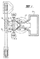
- the illustrated caster comprises a main machine frame 11 which stands up from the factory floor 12.
- Frame 11 supports a casting roll carriage 13 which is horizontally movable between an assembly station 14 and a casting station 15.
- Carriage 13 carries a pair of parallel casting rolls 16 to which molten metal is supplied during a casting operation from a ladle 17 via a tundish 18 and delivery nozzle 19.
- Casting rolls 16 are water cooled so that shells solidify on the moving roll surfaces and are brought together at the nip between them to produce a solidified strip product 20 at the roll outlet.
- This product is fed to a standard coiler 21 and may subsequently be transferred to a second coiler 22.
- a receptacle 23 is mounted on the machine frame adjacent the casting station and molten metal can be diverted into this receptacle via an overflow spout 24 on the tundish or by withdrawal of an emergency plug 25 at one side of the tundish if there is a severe malformation of product or other severe malfunction during a casting operation.
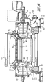
- Roll carriage 13 comprises a carriage frame 31 mounted by wheels 32 on rails 33 extending along part of the main machine frame 11 whereby roll carriage 13 as a whole is mounted for movement along the rails 33.
- Carriage frame 31 carries a pair of roll cradles 34 in which the rolls 16 are rotatably mounted.
- Roll cradles 34 are mounted on the carriage frame 31 by interengaging complementary slide members 35, 36 to allow the cradles to be moved on the carriage under the influence of hydraulic cylinder units 37, 38 to adjust the nip between the casting rolls 16.
- the carriage is movable as a whole along the rails 33 by actuation of a double acting hydraulic piston and cylinder unit 39, connected between a drive bracket 40 on the roll carriage and the main machine frame so as to be actuable to move the roll carriage between the assembly station 14 and casting station 15 and vice versa.
- Casting rolls 16 are contra rotated through drive shafts 41 from an electric motor and transmission mounted on carriage frame 31.
- Rolls 16 have copper peripheral walls formed with a series of longitudinally extending and circumferentially spaced water cooling passages supplied with cooling water through the roll ends from water supply ducts in the roll drive shafts 41 which are connected to water supply hoses 42 through rotary glands 43.
- the rolls may typically be about 500 mm diameter and up to 1300 mm long in order to produce 1300 mm wide strip product.
- Ladle 17 is of entirely conventional construction and is supported via a yoke 45 on an overhead crane whence it can be brought into position from a hot metal receiving station.
- the ladle is fitted with a stopper rod 46 actuable by a servo cylinder to allow molten metal to flow from the ladle through an outlet nozzle 47 and refractory shroud 48 into tundish 18.
- Tundish 18 is also of conventional construction. It is formed as a wide dish made of a refractory material such as magnesium oxide (MgO). One side of the tundish receives molten metal from the ladle and is provided with the aforesaid overflow 24 and emergency plug 25. The other side of the tundish is provided with a series of longitudinally spaced metal outlet openings 52. The lower part of the tundish carries mounting brackets 53 for mounting the tundish onto the roll carriage frame 31 and provided with apertures to receive indexing pegs 54 on the carriage frame so as to accurately locate the tundish.
- MgO magnesium oxide
- Delivery nozzle 19 is formed as an elongate body made of a refractory material such as alumina graphite. Its lower part is tapered so as to converge inwardly and downwardly so that it can project into the nip between casting rolls 16. It is provided with a mounting bracket 60 whereby to support it on the roll carriage frame and its upper part is formed with outwardly projecting side flanges 55 which locate on the mounting bracket.
- a refractory material such as alumina graphite.
- Nozzle 19 may have a series of horizontally spaced generally vertically extending flow passages to produce a suitably low velocity discharge of metal throughout the width of the rolls and to deliver the molten metal into the nip between the rolls without direct impingement on the roll surfaces at which initial solidification occurs.
- the nozzle may have a single continuous slot outlet to deliver a low velocity curtain of molten metal directly into the nip between the rolls and/or it may be immersed in the molten metal pool.
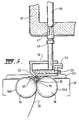
- the pool is confined at the ends of the rolls by a pair of side closure plates 56 which are held against stepped ends 57 of the rolls when the roll carriage is at the casting station.
- Side closure plates 56 are made of a strong refractory material, for example boron nitride, and have scalloped side edges 81 to match the curvature of the stepped ends 57 of the rolls.
- the side plates can be mounted in plate holders 82 which are movable at the casting station by actuation of a pair of hydraulic cylinder units 83 to bring the side plates into engagement with the stepped ends of the casting rolls to form end closures for the molten pool of metal formed on the casting rolls during a casting operation.
- the ladle stopper rod 46 is actuated to allow molten metal to pour from the ladle to the tundish through the metal delivery nozzle whence it flows to the casting rolls.
- the clean head end of the strip product 20 is guided by actuation of an apron table 96 to the jaws of the coiler 21.
- Apron table 96 hangs from pivot mountings 97 on the main frame and can be swung toward the coiler by actuation of an hydraulic cylinder unit 98 after the clean head end has been formed.
- Table 96 may operate against an upper strip guide flap 99 actuated by a piston and a cylinder unit 101 and the strip product 20 may be confined between a pair of vertical side rollers 102.
- the coiler is rotated to coil the strip product 20 and the apron table is allowed to swing back to its inoperative position where it simply hangs from the machine frame clear of the product which is taken directly onto the coiler 21.
- the resulting strip product 20 may be subsequently transferred to coiler 22 to produce a final coil for transport away from the caster.
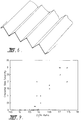
- Tests were conducted on three copper substrates with different surface characteristics; a smooth and a textured copper surface and a Cr coated (100 ⁇ m in thickness), ground surface. Texture was imparted to the copper block by machining longitudinal grooves and ridges with geometry shown schematically in Figure 6. Each of these blocks was instrumented with thermocouples to characterise the heat transfer rates prevailing during solidification. In order to maintain consistent casting conditions throughout the experiments, variables such as melt superheat and block temperature were kept constant within reasonable limits. The melt temperature was aimed at about 1525°C corresponding to a superheat of 75°C. Argon gas introduced into the furnace was quite effective in preventing chemical interaction of the melt with the surrounding atmosphere.
- the melt chemistry was adjusted to achieve the desired (Cr/Ni) eq ratios, primarily through additions of Cr, Ni, C and N 2 .
- Heat transfer rates from the strip surface to the substrate were determined from the measured substrate temperatures.
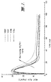
- Figure 7 shows the influence of melt (Cr/Ni) eq ratio on heat fluxes for a textured substrate. It can be seen that the profiles are characterised by an early peak in the heat flux followed by rapid reduction of this peak and with increasing time, heat flux approaches a constant value. Higher heat transfer rates (about 30 MW/m 2 ) encountered in the early stages of solidification can be attributed to the intimate contact.
- the experimental program determined that the (Cr/Ni) eq ratio found to producing the best surface texture (on a textured substrate) is less than 1.60.
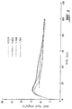
- Figure 8 reveals the influence of (Cr/Ni) eq ratio on heat transfer for a smooth substrate. It can be seen that the heat fluxes are relatively constant throughout solidification and most importantly, the magnitudes of the peak fluxes are much lower than those measured for a textured substrate ( Figure 7). This finding is in agreement with the observed solidification structure which is coarse at the surface. Although there are some variations in heat flux at different (Cr/Ni) eq ratios, there are no definite trends. However, with increasing time the heat fluxes approach similar values irrespective of (Cr/Ni) eq . This apparent lack of dependence of heat transfer on (Cr/Ni) eq ratio with a smooth substrate is in agreement with the observations of strip surface texture which was not influenced by (Cr/Ni) eq .
Landscapes
- Engineering & Computer Science (AREA)
- Mechanical Engineering (AREA)
- Continuous Casting (AREA)
- Coating With Molten Metal (AREA)
- Metal Rolling (AREA)
- Preventing Corrosion Or Incrustation Of Metals (AREA)
- Pressure Welding/Diffusion-Bonding (AREA)
- Treatment Of Steel In Its Molten State (AREA)
- Surgical Instruments (AREA)
Abstract
Description
| Carbon - | 0.04 - 0.06 % by weight |
| Chromium - | 17.5 - 19.5 % by weight |
| Nickel - | 8.0 - 10.0 % by weight. |
| Experimental conditions | |
| Substrate surface | Smooth copper Cr plated (ground) copper Textured copper (150µm pitch, 20µm depth) |
| Substrate cleaning procedure | Bristle brush and air blowing |
| Melt temperature | 1525°C |
| Block temperature | 125°C |
| Details of the various tests | |||||
| CONDITION | (Cr/Ni)eq | MELT N2 | GAS | TOTAL DIPS | |
| 1 | 1.56-1.71 | 0.047 | | 9 | |
| 2 | 1.58-1.71 | 0.037 | | 9 | |
| 3 | 1.57-1.61 | <0.062 | N2 | 7 | |
| 4 | 1.59 | 0.062 | Ar | 7 | |
| 5 | 1.74 | 0.054-0.059 | Ar Ar + | 15 |
Claims (14)
- A method of continuously casting metal strip of the kind in which a casting pool of molten metal is formed in contact with a moving casting surface such that metal solidifies from the pool onto the moving casting surface, wherein the metal is an austenitic stainless steel containing chromium and nickel in a ratio (Cr/Ni)eq of less than 1.60 and the casting surface has an Arithmetical Mean Roughness Value (Ra) of more than 2.5 microns.
- A method as claimed in claim 1, wherein the Arithmetical Mean Roughness Value (Ra) of the casting surface is in the range 2.5 to 15 microns.
- A method as claimed in claim 2, wherein the casting surface has a texture of regular grooves and ridges.
- A method as claimed in claim 3, wherein the texture depth is in the range 10 microns to 60 microns and the groove pitch is in the range 100 microns to 200 microns.
- A method as claimed in claim 3, wherein the casting surface has a texture of regularly spaced discrete projections at a pitch spacing in the range 100 to 200 microns and a texture depth in the range 10 to 60 microns.
- A method as claimed in any one of the preceding claims, wherein the chromium to nickel ratio is no greater than 1.55.
- A method as claimed in any one of the preceding claims wherein the carbon, chromium and nickel contents of the steel are in the following ranges:
Carbon - 0.04 - 0.06 % by weight Chromium - 17.5 - 19.5 % by weight Nickel - 8.0 - 10.0 % by weight. - A method of continuously casting metal strip of the kind in which molten metal is introduced into the nip between a pair of casting rollers via metal delivery nozzle disposed above the nip to create a casting pool of molten metal supported on casting surfaces of the rolls immediately above the nip and the casting rolls are rotated to deliver a solidified metal strip downwardly from the nip, wherein the metal is an austenitic stainless steel containing chromium and nickel in a ratio (Cr/Ni) of less than 1.60 and the casting surfaces of the rolls have an Arithmetical Mean Roughness Value (Ra) of greater than 2.5 microns.
- A method as claimed in claim 8, wherein the Arithmetical Mean Roughness Value (Ra) of the casting surfaces of the rolls is in the range 2.5 to 15 microns.
- A method as claimed in claim 9, wherein the casting surfaces of the rolls have a texture of regular circumferential grooves with a texture depth in the range 10 microns to 60 microns and a groove pitch in the range 100 microns to 200 microns.
- A method as claimed in claim 9, wherein the rolls have a texture of regularly spaced discrete projections at a pitch spacing in the range 100 to 200 microns and a depth in the range 10 to 60 microns.
- A method as claimed in any one of claims 8 to 11, wherein the chromium to nickel ratio is no greater than 1.55.
- A method as claimed in any one of claims 8 to 12, wherein the carbon, chromium and nickel content of the steel are in the following ranges:
Carbon - 0.04 - 0.06 % by weight Chromium - 17.5 - 19.5 % by weight Nickel - 8.0 - 10.0 % by weight. - A method as claimed in any one of the preceding claims, wherein heat is transferred from said austenitic stainless steel solidifying onto the casting surface at an initial peak heat transfer rate of more than 15 MW/m2 within the initial 20ms of the contact, said heat transfer rate being sufficiently high to enable the solidification of said steel on the casting surface without deleterious segregation and surface cracking.
Applications Claiming Priority (4)
| Application Number | Priority Date | Filing Date | Title |
|---|---|---|---|
| AUPM2539/93 | 1993-11-18 | ||
| AUPM253993 | 1993-11-18 | ||
| AUPM253993 | 1993-11-18 | ||
| PCT/AU1994/000685 WO1995013889A1 (en) | 1993-11-18 | 1994-11-09 | Casting stainless steel strip on surface with specified roughness |
Publications (4)
| Publication Number | Publication Date |
|---|---|
| EP0679114A1 EP0679114A1 (en) | 1995-11-02 |
| EP0679114A4 EP0679114A4 (en) | 1997-03-19 |
| EP0679114B1 true EP0679114B1 (en) | 1999-07-21 |
| EP0679114B2 EP0679114B2 (en) | 2004-11-03 |
Family
ID=3777367
Family Applications (1)
| Application Number | Title | Priority Date | Filing Date |
|---|---|---|---|
| EP95900015A Expired - Lifetime EP0679114B2 (en) | 1993-11-18 | 1994-11-09 | Casting stainless steel strip on surface with specified roughness |
Country Status (12)
| Country | Link |
|---|---|
| EP (1) | EP0679114B2 (en) |
| JP (1) | JPH08505811A (en) |
| KR (1) | KR100305291B1 (en) |
| AT (1) | ATE182284T1 (en) |
| DE (1) | DE69419593T3 (en) |
| DK (1) | DK0679114T4 (en) |
| ES (1) | ES2134427T5 (en) |
| FI (1) | FI101944B1 (en) |
| GR (1) | GR3031222T3 (en) |
| TW (1) | TW276200B (en) |
| WO (1) | WO1995013889A1 (en) |
| ZA (1) | ZA949134B (en) |
Cited By (1)
| Publication number | Priority date | Publication date | Assignee | Title |
|---|---|---|---|---|
| US8122937B2 (en) | 2007-10-12 | 2012-02-28 | Nucor Corporation | Method of forming textured casting rolls with diamond engraving |
Families Citing this family (17)
| Publication number | Priority date | Publication date | Assignee | Title |
|---|---|---|---|---|
| AUPN281195A0 (en) * | 1995-05-05 | 1995-06-01 | Bhp Steel (Jla) Pty Limited | Casting steel strip |
| FR2746333B1 (en) * | 1996-03-22 | 1998-04-24 | Usinor Sacilor | METHOD FOR CONTINUOUSLY CASTING A AUSTENITIC STAINLESS STEEL STRIP ON OR BETWEEN TWO MOBILE WALLS WITH SURFACES PROVIDED WITH PITCHES, AND CASTING INSTALLATION FOR IMPLEMENTING SAME |
| KR100650967B1 (en) * | 1996-03-22 | 2007-01-31 | 티쎈 스탈 아게 | Process for the continuous casting of an austenitic stainless steel strip onto one or between two moving walls with dimpled surfaces, and casting plant for its implementation |
| AUPO710497A0 (en) * | 1997-06-02 | 1997-06-26 | Bhp Steel (Jla) Pty Limited | Casting metal strip |
| AUPP515198A0 (en) * | 1998-08-07 | 1998-09-03 | Bhp Steel (Jla) Pty Limited | Casting steel strip |
| US6942013B2 (en) | 1998-08-07 | 2005-09-13 | Lazar Strezov | Casting steel strip |
| US7073565B2 (en) | 1999-02-05 | 2006-07-11 | Castrip, Llc | Casting steel strip |
| FR2791286B1 (en) * | 1999-03-26 | 2001-05-04 | Lorraine Laminage | PROCESS FOR PRODUCING CARBON STEEL STRIPS BY CONTINUOUS CASTING BETWEEN TWO CYLINDERS |
| FR2792560B1 (en) * | 1999-04-22 | 2001-06-01 | Usinor | CONTINUOUS CASTING PROCESS BETWEEN AUSTENITIC STAINLESS STEEL TAPE CYLINDERS OF EXCELLENT SURFACE QUALITY AND BANDS THUS OBTAINED |
| CH691575A5 (en) * | 1999-10-08 | 2001-08-31 | Main Man Inspiration Ag | The strip casting machine for producing a metal strip, and method for operating same. |
| AT412072B (en) | 2002-10-15 | 2004-09-27 | Voest Alpine Ind Anlagen | METHOD FOR THE CONTINUOUS PRODUCTION OF A THIN STEEL STRIP |
| EP1594640B1 (en) | 2003-01-24 | 2014-04-23 | Nucor Corporation | Casting steel strip |
| US20040144518A1 (en) | 2003-01-24 | 2004-07-29 | Blejde Walter N. | Casting steel strip with low surface roughness and low porosity |
| US9149868B2 (en) | 2005-10-20 | 2015-10-06 | Nucor Corporation | Thin cast strip product with microalloy additions, and method for making the same |
| US10071416B2 (en) | 2005-10-20 | 2018-09-11 | Nucor Corporation | High strength thin cast strip product and method for making the same |
| US9999918B2 (en) | 2005-10-20 | 2018-06-19 | Nucor Corporation | Thin cast strip product with microalloy additions, and method for making the same |
| US20110277886A1 (en) | 2010-02-20 | 2011-11-17 | Nucor Corporation | Nitriding of niobium steel and product made thereby |
Family Cites Families (5)
| Publication number | Priority date | Publication date | Assignee | Title |
|---|---|---|---|---|
| EP0378705B2 (en) † | 1988-07-08 | 1999-09-15 | Nippon Steel Corporation | PROCESS FOR PRODUCING THIN Cr-Ni STAINLESS STEEL SHEET EXCELLENT IN BOTH SURFACE QUALITY AND QUALITY OF MATERIAL |
| FR2655893B1 (en) * | 1989-12-20 | 1992-04-17 | Siderurgie Fse Inst Rech | DEVICE FOR CASTING THIN METAL STRIPS BETWEEN TWO ROTATING AND PARALLEL CYLINDERS OR ON A SINGLE CYLINDER. |
| JPH082484B2 (en) * | 1990-10-19 | 1996-01-17 | 新日本製鐵株式会社 | Austenitic stainless steel strip-shaped slab with excellent surface quality, thin plate manufacturing method, and strip-shaped slab |
| GB9123603D0 (en) * | 1991-11-06 | 1992-01-02 | Davy Mckee Poole | A roll for a twin roll caster |
| FR2684904B1 (en) * | 1991-12-11 | 1994-03-18 | Usinor Sacilor | CYLINDER FOR A CONTINUOUS CASTING MACHINE FOR METAL STRIPS, CORRESPONDING CONTINUOUS CASTING MACHINE AND METHOD FOR PRODUCING SUCH A CYLINDER. |
-
1994
- 1994-11-09 ES ES95900015T patent/ES2134427T5/en not_active Expired - Lifetime
- 1994-11-09 DK DK95900015T patent/DK0679114T4/en active
- 1994-11-09 WO PCT/AU1994/000685 patent/WO1995013889A1/en not_active Ceased
- 1994-11-09 EP EP95900015A patent/EP0679114B2/en not_active Expired - Lifetime
- 1994-11-09 KR KR1019950701830A patent/KR100305291B1/en not_active Expired - Lifetime
- 1994-11-09 DE DE69419593T patent/DE69419593T3/en not_active Expired - Lifetime
- 1994-11-09 JP JP7514101A patent/JPH08505811A/en active Pending
- 1994-11-09 AT AT95900015T patent/ATE182284T1/en not_active IP Right Cessation
- 1994-11-17 ZA ZA949134A patent/ZA949134B/en unknown
- 1994-11-21 TW TW083110812A patent/TW276200B/zh active
-
1995
- 1995-04-26 FI FI951985A patent/FI101944B1/en active
-
1999
- 1999-09-16 GR GR990402313T patent/GR3031222T3/en unknown
Cited By (1)
| Publication number | Priority date | Publication date | Assignee | Title |
|---|---|---|---|---|
| US8122937B2 (en) | 2007-10-12 | 2012-02-28 | Nucor Corporation | Method of forming textured casting rolls with diamond engraving |
Also Published As
| Publication number | Publication date |
|---|---|
| DK0679114T4 (en) | 2004-12-13 |
| EP0679114A4 (en) | 1997-03-19 |
| FI951985L (en) | 1995-05-19 |
| DE69419593D1 (en) | 1999-08-26 |
| DK0679114T3 (en) | 2000-02-07 |
| JPH08505811A (en) | 1996-06-25 |
| TW276200B (en) | 1996-05-21 |
| KR100305291B1 (en) | 2001-11-22 |
| DE69419593T3 (en) | 2005-06-09 |
| DE69419593T2 (en) | 1999-11-18 |
| KR950704070A (en) | 1995-11-17 |
| WO1995013889A1 (en) | 1995-05-26 |
| FI101944B (en) | 1998-09-30 |
| ES2134427T3 (en) | 1999-10-01 |
| ES2134427T5 (en) | 2005-05-16 |
| EP0679114A1 (en) | 1995-11-02 |
| GR3031222T3 (en) | 1999-12-31 |
| EP0679114B2 (en) | 2004-11-03 |
| ATE182284T1 (en) | 1999-08-15 |
| ZA949134B (en) | 1995-07-24 |
| FI951985A0 (en) | 1995-04-26 |
| FI101944B1 (en) | 1998-09-30 |
Similar Documents
| Publication | Publication Date | Title |
|---|---|---|
| EP0679114B2 (en) | Casting stainless steel strip on surface with specified roughness | |
| US7281569B2 (en) | Casting steel strip with low surface roughness and low porosity | |
| EP0732163B1 (en) | Method for casting of metal | |
| EP0800881B1 (en) | Casting steel strip | |
| EP0740972B1 (en) | Casting steel strip | |
| US6059014A (en) | Casting steel strip | |
| US6942013B2 (en) | Casting steel strip | |
| EP1100638B1 (en) | Casting steel strip | |
| US7073565B2 (en) | Casting steel strip | |
| US5983980A (en) | Casting steel strip | |
| EP1029617B1 (en) | Continuous casting steel strip method | |
| AU676101B2 (en) | Casting stainless steel strip on surface with specified roughness | |
| US20030062146A1 (en) | Amorphous or glassy alloy surfaced rolls for the continuous casting of metal strip | |
| AU724072B2 (en) | Casting steel strip | |
| AU696684B2 (en) | Casting steel strip | |
| AU746006B2 (en) | Casting steel strip |
Legal Events
| Date | Code | Title | Description |
|---|---|---|---|
| PUAI | Public reference made under article 153(3) epc to a published international application that has entered the european phase |
Free format text: ORIGINAL CODE: 0009012 |
|
| 17P | Request for examination filed |
Effective date: 19950424 |
|
| AK | Designated contracting states |
Kind code of ref document: A1 Designated state(s): AT BE CH DE DK ES FR GB GR IE IT LI LU MC NL PT SE |
|
| A4 | Supplementary search report drawn up and despatched |
Effective date: 19970131 |
|
| AK | Designated contracting states |
Kind code of ref document: A4 Designated state(s): AT BE CH DE DK ES FR GB GR IE IT LI LU MC NL PT SE |
|
| GRAG | Despatch of communication of intention to grant |
Free format text: ORIGINAL CODE: EPIDOS AGRA |
|
| 17Q | First examination report despatched |
Effective date: 19980604 |
|
| GRAG | Despatch of communication of intention to grant |
Free format text: ORIGINAL CODE: EPIDOS AGRA |
|
| GRAG | Despatch of communication of intention to grant |
Free format text: ORIGINAL CODE: EPIDOS AGRA |
|
| GRAH | Despatch of communication of intention to grant a patent |
Free format text: ORIGINAL CODE: EPIDOS IGRA |
|
| GRAH | Despatch of communication of intention to grant a patent |
Free format text: ORIGINAL CODE: EPIDOS IGRA |
|
| GRAA | (expected) grant |
Free format text: ORIGINAL CODE: 0009210 |
|
| AK | Designated contracting states |
Kind code of ref document: B1 Designated state(s): AT BE CH DE DK ES FR GB GR IE IT LI LU MC NL PT SE |
|
| REF | Corresponds to: |
Ref document number: 182284 Country of ref document: AT Date of ref document: 19990815 Kind code of ref document: T |
|
| REG | Reference to a national code |
Ref country code: CH Ref legal event code: NV Representative=s name: R. A. EGLI & CO. PATENTANWAELTE Ref country code: CH Ref legal event code: EP |
|
| ITF | It: translation for a ep patent filed | ||
| REF | Corresponds to: |
Ref document number: 69419593 Country of ref document: DE Date of ref document: 19990826 |
|
| ET | Fr: translation filed | ||
| REG | Reference to a national code |
Ref country code: IE Ref legal event code: FG4D |
|
| REG | Reference to a national code |
Ref country code: ES Ref legal event code: FG2A Ref document number: 2134427 Country of ref document: ES Kind code of ref document: T3 |
|
| REG | Reference to a national code |
Ref country code: PT Ref legal event code: SC4A Free format text: AVAILABILITY OF NATIONAL TRANSLATION Effective date: 19990722 |
|
| REG | Reference to a national code |
Ref country code: DK Ref legal event code: T3 |
|
| PLBQ | Unpublished change to opponent data |
Free format text: ORIGINAL CODE: EPIDOS OPPO |
|
| PLBI | Opposition filed |
Free format text: ORIGINAL CODE: 0009260 |
|
| PLBF | Reply of patent proprietor to notice(s) of opposition |
Free format text: ORIGINAL CODE: EPIDOS OBSO |
|
| PG25 | Lapsed in a contracting state [announced via postgrant information from national office to epo] |
Ref country code: MC Free format text: LAPSE BECAUSE OF NON-PAYMENT OF DUE FEES Effective date: 20000531 |
|
| 26 | Opposition filed |
Opponent name: USINOR Effective date: 20000425 |
|
| NLR1 | Nl: opposition has been filed with the epo |
Opponent name: USINOR |
|
| PLBF | Reply of patent proprietor to notice(s) of opposition |
Free format text: ORIGINAL CODE: EPIDOS OBSO |
|
| PLBF | Reply of patent proprietor to notice(s) of opposition |
Free format text: ORIGINAL CODE: EPIDOS OBSO |
|
| REG | Reference to a national code |
Ref country code: CH Ref legal event code: PUE Owner name: BHP STEEL (JLA) PTY. LTD. TRANSFER- CASTRIP, LLC |
|
| REG | Reference to a national code |
Ref country code: GB Ref legal event code: IF02 |
|
| NLS | Nl: assignments of ep-patents |
Owner name: CASTRIP, LLC |
|
| RDAH | Patent revoked |
Free format text: ORIGINAL CODE: EPIDOS REVO |
|
| REG | Reference to a national code |
Ref country code: PT Ref legal event code: TE4A Free format text: BHP STEEL (JLA) PTY. LTD. AU Effective date: 20011214 Ref country code: PT Ref legal event code: PC4A Free format text: CASTRIP, LLC US Effective date: 20011218 |
|
| APAC | Appeal dossier modified |
Free format text: ORIGINAL CODE: EPIDOS NOAPO |
|
| REG | Reference to a national code |
Ref country code: GB Ref legal event code: 732E |
|
| APAC | Appeal dossier modified |
Free format text: ORIGINAL CODE: EPIDOS NOAPO |
|
| RAP2 | Party data changed (patent owner data changed or rights of a patent transferred) |
Owner name: CASTRIP, LLC |
|
| REG | Reference to a national code |
Ref country code: FR Ref legal event code: TP |
|
| NLT2 | Nl: modifications (of names), taken from the european patent patent bulletin |
Owner name: CASTRIP, LLC |
|
| APBU | Appeal procedure closed |
Free format text: ORIGINAL CODE: EPIDOSNNOA9O |
|
| PUAH | Patent maintained in amended form |
Free format text: ORIGINAL CODE: 0009272 |
|
| STAA | Information on the status of an ep patent application or granted ep patent |
Free format text: STATUS: PATENT MAINTAINED AS AMENDED |
|
| 27A | Patent maintained in amended form |
Effective date: 20041103 |
|
| AK | Designated contracting states |
Kind code of ref document: B2 Designated state(s): AT BE CH DE DK ES FR GB GR IE IT LI LU MC NL PT SE |
|
| REG | Reference to a national code |
Ref country code: CH Ref legal event code: AEN Free format text: MAINTIEN DU BREVET DONT L'ETENDUE A ETE MODIFIEE |
|
| REG | Reference to a national code |
Ref country code: SE Ref legal event code: RPEO |
|
| REG | Reference to a national code |
Ref country code: DK Ref legal event code: T4 |
|
| NLR2 | Nl: decision of opposition |
Effective date: 20041103 |
|
| APAA | Appeal reference recorded |
Free format text: ORIGINAL CODE: EPIDOS REFN |
|
| REG | Reference to a national code |
Ref country code: GR Ref legal event code: EP Ref document number: 20050400277 Country of ref document: GR |
|
| NLR3 | Nl: receipt of modified translations in the netherlands language after an opposition procedure | ||
| REG | Reference to a national code |
Ref country code: ES Ref legal event code: DC2A Date of ref document: 20050128 Kind code of ref document: T5 |
|
| APAH | Appeal reference modified |
Free format text: ORIGINAL CODE: EPIDOSCREFNO |
|
| ET3 | Fr: translation filed ** decision concerning opposition | ||
| PLAB | Opposition data, opponent's data or that of the opponent's representative modified |
Free format text: ORIGINAL CODE: 0009299OPPO |
|
| PGFP | Annual fee paid to national office [announced via postgrant information from national office to epo] |
Ref country code: NL Payment date: 20081103 Year of fee payment: 15 Ref country code: LU Payment date: 20081119 Year of fee payment: 15 Ref country code: IE Payment date: 20081114 Year of fee payment: 15 Ref country code: DK Payment date: 20081114 Year of fee payment: 15 Ref country code: CH Payment date: 20081117 Year of fee payment: 15 |
|
| PGFP | Annual fee paid to national office [announced via postgrant information from national office to epo] |
Ref country code: PT Payment date: 20081024 Year of fee payment: 15 Ref country code: ES Payment date: 20081216 Year of fee payment: 15 Ref country code: AT Payment date: 20081112 Year of fee payment: 15 |
|
| PGFP | Annual fee paid to national office [announced via postgrant information from national office to epo] |
Ref country code: BE Payment date: 20081110 Year of fee payment: 15 Ref country code: SE Payment date: 20081107 Year of fee payment: 15 Ref country code: IT Payment date: 20081126 Year of fee payment: 15 |
|
| PGFP | Annual fee paid to national office [announced via postgrant information from national office to epo] |
Ref country code: GR Payment date: 20081031 Year of fee payment: 15 Ref country code: GB Payment date: 20081105 Year of fee payment: 15 |
|
| REG | Reference to a national code |
Ref country code: PT Ref legal event code: MM4A Free format text: LAPSE DUE TO NON-PAYMENT OF FEES Effective date: 20100510 |
|
| BERE | Be: lapsed |
Owner name: *CASTRIP LLC Effective date: 20091130 |
|
| REG | Reference to a national code |
Ref country code: NL Ref legal event code: V1 Effective date: 20100601 |
|
| EUG | Se: european patent has lapsed | ||
| REG | Reference to a national code |
Ref country code: CH Ref legal event code: PL |
|
| REG | Reference to a national code |
Ref country code: DK Ref legal event code: EBP |
|
| GBPC | Gb: european patent ceased through non-payment of renewal fee |
Effective date: 20091109 |
|
| PG25 | Lapsed in a contracting state [announced via postgrant information from national office to epo] |
Ref country code: PT Free format text: LAPSE BECAUSE OF NON-PAYMENT OF DUE FEES Effective date: 20100510 |
|
| REG | Reference to a national code |
Ref country code: IE Ref legal event code: MM4A |
|
| PG25 | Lapsed in a contracting state [announced via postgrant information from national office to epo] |
Ref country code: AT Free format text: LAPSE BECAUSE OF NON-PAYMENT OF DUE FEES Effective date: 20091109 |
|
| PG25 | Lapsed in a contracting state [announced via postgrant information from national office to epo] |
Ref country code: NL Free format text: LAPSE BECAUSE OF NON-PAYMENT OF DUE FEES Effective date: 20100601 Ref country code: LI Free format text: LAPSE BECAUSE OF NON-PAYMENT OF DUE FEES Effective date: 20091130 Ref country code: IE Free format text: LAPSE BECAUSE OF NON-PAYMENT OF DUE FEES Effective date: 20091109 Ref country code: GR Free format text: LAPSE BECAUSE OF NON-PAYMENT OF DUE FEES Effective date: 20100602 Ref country code: CH Free format text: LAPSE BECAUSE OF NON-PAYMENT OF DUE FEES Effective date: 20091130 Ref country code: BE Free format text: LAPSE BECAUSE OF NON-PAYMENT OF DUE FEES Effective date: 20091130 |
|
| PG25 | Lapsed in a contracting state [announced via postgrant information from national office to epo] |
Ref country code: GB Free format text: LAPSE BECAUSE OF NON-PAYMENT OF DUE FEES Effective date: 20091109 |
|
| PG25 | Lapsed in a contracting state [announced via postgrant information from national office to epo] |
Ref country code: DK Free format text: LAPSE BECAUSE OF NON-PAYMENT OF DUE FEES Effective date: 20091130 |
|
| REG | Reference to a national code |
Ref country code: ES Ref legal event code: FD2A Effective date: 20110304 |
|
| PG25 | Lapsed in a contracting state [announced via postgrant information from national office to epo] |
Ref country code: IT Free format text: LAPSE BECAUSE OF NON-PAYMENT OF DUE FEES Effective date: 20091109 |
|
| PG25 | Lapsed in a contracting state [announced via postgrant information from national office to epo] |
Ref country code: LU Free format text: LAPSE BECAUSE OF NON-PAYMENT OF DUE FEES Effective date: 20091109 |
|
| PG25 | Lapsed in a contracting state [announced via postgrant information from national office to epo] |
Ref country code: SE Free format text: LAPSE BECAUSE OF NON-PAYMENT OF DUE FEES Effective date: 20091110 |
|
| PG25 | Lapsed in a contracting state [announced via postgrant information from national office to epo] |
Ref country code: ES Free format text: LAPSE BECAUSE OF NON-PAYMENT OF DUE FEES Effective date: 20110303 |
|
| PG25 | Lapsed in a contracting state [announced via postgrant information from national office to epo] |
Ref country code: ES Free format text: LAPSE BECAUSE OF NON-PAYMENT OF DUE FEES Effective date: 20091110 |
|
| PGFP | Annual fee paid to national office [announced via postgrant information from national office to epo] |
Ref country code: FR Payment date: 20131108 Year of fee payment: 20 Ref country code: DE Payment date: 20131106 Year of fee payment: 20 |
|
| REG | Reference to a national code |
Ref country code: DE Ref legal event code: R071 Ref document number: 69419593 Country of ref document: DE |
|
| REG | Reference to a national code |
Ref country code: DE Ref legal event code: R071 Ref document number: 69419593 Country of ref document: DE |