EP0678971A2 - Method of reversing the direction of rotation for a brushless DC motor from full speed and brushless DC motor - Google Patents
Method of reversing the direction of rotation for a brushless DC motor from full speed and brushless DC motor Download PDFInfo
- Publication number
- EP0678971A2 EP0678971A2 EP95104877A EP95104877A EP0678971A2 EP 0678971 A2 EP0678971 A2 EP 0678971A2 EP 95104877 A EP95104877 A EP 95104877A EP 95104877 A EP95104877 A EP 95104877A EP 0678971 A2 EP0678971 A2 EP 0678971A2
- Authority
- EP
- European Patent Office
- Prior art keywords
- motor
- rotation
- brushless
- speed
- switch
- Prior art date
- Legal status (The legal status is an assumption and is not a legal conclusion. Google has not performed a legal analysis and makes no representation as to the accuracy of the status listed.)
- Granted
Links
Images
Classifications
-
- H—ELECTRICITY
- H02—GENERATION; CONVERSION OR DISTRIBUTION OF ELECTRIC POWER
- H02P—CONTROL OR REGULATION OF ELECTRIC MOTORS, ELECTRIC GENERATORS OR DYNAMO-ELECTRIC CONVERTERS; CONTROLLING TRANSFORMERS, REACTORS OR CHOKE COILS
- H02P6/00—Arrangements for controlling synchronous motors or other dynamo-electric motors using electronic commutation dependent on the rotor position; Electronic commutators therefor
- H02P6/30—Arrangements for controlling the direction of rotation
Definitions
- the invention relates to a method for reversing the direction of rotation of a brushless DC motor at full speed, which has a single-quadrant controller with switchable direction of rotation.
- a brushless DC motor with a single quadrant controller with a switchable direction of rotation is known (cf. publication: "Control electronics BGE 2406, operating instructions of the applicant). These brushless DC motors are used for applications in which it is necessary to reverse the direction of rotation as quickly as possible If the direct current motor switched the direction of rotation at full speed, very high motor currents would occur, which could correspond to twice the starting current, and energy would be fed back into the speed controller, which could lead to its destruction. To avoid these dangers, it is therefore common and It is necessary to let the motor run to a standstill before reversing the direction of rotation.
- the technical problem underlying the invention therefore consists in specifying a method with which the reversal of the direction of rotation of such a brushless DC motor can be carried out in a shorter period of time and a suitable brushless DC motor with control.
- This technical problem is solved according to the invention in that, after switching the direction of rotation, a short-circuit braking of the motor is carried out automatically, that the speed of the motor is then checked and the short-circuit braking is released when the speed has reached a value close to 0 min ⁇ 1.
- the reversal of the direction of rotation can be initiated at any time without the risk of damage, and moreover the reversal of the direction of rotation takes place more quickly than before.
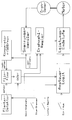
- the brushless DC motor consists of the motor 1 and the control logic 2 and the power output stage 3.
- the DC voltage supply for the brushless DC motor is switched on and off with the switch 4.
- the rotary encoder 5, which can be an incremental rotary encoder or a tachometer generator, is coupled to the rotor of the motor 1. If the rotary encoder 5 is an incremental rotary encoder which delivers a pulse sequence corresponding to the speed, the voltage converter 6 is a frequency-voltage converter which supplies a DC voltage proportional to the speed, which is compared in the speed controller 7 with a DC voltage corresponding to the target speed and off a control variable may be generated for the comparison.
- the setpoint speed can be specified from the outside by a corresponding DC voltage by the user of the motor.
- the setpoint generator is the tap of a potentiometer, which is connected to a DC voltage of 10 V.
- the direction of rotation of the motor 1 is controlled, for example, in such a way that the motor rotates to the right when the direction of rotation switch 8 is closed and to the left when the direction of rotation switch 8 is open.
- the Control logic 2 controls the power output stage 3 as a function of the position of the switches 4, 8 and 9 and the changeover switch 10, ie. it causes the power output stage 3 to either be blocked or released, to switch to short-circuit braking or to switch between left and right running.
- the DC voltage corresponding to the actual speed is also fed from the voltage converter 6 to the comparator 11, which checks whether the speed is higher or lower than a comparison speed, e.g. 500 min ⁇ 1.
- a comparison speed e.g. 500 min ⁇ 1.
- the electronic switch 12 (flip-flop) and the edge detector 13 are also present.
- the edge detector is controlled by the direction of rotation switch 8 (right / left).
- the electronic switch 12 (flip-flop) is controlled both by the edge detector 13 and by the comparator 11.
- the switch 10 has two positions: either it switches the electronic switch 12 or the switch 9 to the control logic 2. By closing the switch 9, the short-circuit braking of the motor is initiated manually.
- the automatic braking of the motor if applicable, is implemented in the following way: Assume that switch 4 is closed and switches 8 and 9 are open. In such a case, the motor runs counterclockwise. If the direction of rotation of the motor is to be reversed, then the direction of rotation switch 8 is closed. As a result, the potential at the switch output changes from 0 V to 12 V, for example.
- the edge detector 13 can be a monostable flip-flop which, triggered on an edge, tilts into a working state and tilts back into the initial state after a fixed holding time.
- the changeover switch 10 is also actuated, whereby manual short-circuit braking of the motor is initiated.
Landscapes
- Engineering & Computer Science (AREA)
- Power Engineering (AREA)
- Control Of Motors That Do Not Use Commutators (AREA)
Abstract
Description
Die Erfindung betrifft ein Verfahren zur Umkehr der Drehrichtung eines bürstenlosen Gleichstrommotor aus vollem Lauf, welcher einen Einquadrantenregler mit umschaltbarer Drehrichtung besitzt.The invention relates to a method for reversing the direction of rotation of a brushless DC motor at full speed, which has a single-quadrant controller with switchable direction of rotation.
Ein bürstenloser Gleichstrommotor mit einem Einquadrantenregler mit umschaltbarer Drehrichtung ist bekannt (vgl. Druckschrift: "Regelelektronik BGE 2406, Betriebanleitung der Anmelderin). Diese bürstenlosen Gleichstrommotoren werden für Anwendungsfälle eingesetzt, bei denen es erforderlich, eine Drehrichtungsumkehr möglichst rasch vorzunehmen. Wenn man bei dem bekannten Gleichstrommotor die Drehrichtung in vollem Lauf umschalten würde, dann würden sehr hohe Motorströme auftreten, welche etwa dem doppelten Anlaufstrom entsprechen können. Außerdem wird Energie in den Drehzahlregler zurückgespeist, welches zu dessen Zerstörung führen kann. Um diese Gefahren zu vermeiden, ist es deshalb üblich und notwendig, den Motor bis zum Stillstand aus laufen zu lassen, bevor die Drehrichtungsumkehr eingeleitet wird. Bei einem solchen Vorgehen nimmt die Drehrichtungsumkehr eine verhältnismäßig große Zeitspanne in Anspruch.A brushless DC motor with a single quadrant controller with a switchable direction of rotation is known (cf. publication: "Control electronics BGE 2406, operating instructions of the applicant). These brushless DC motors are used for applications in which it is necessary to reverse the direction of rotation as quickly as possible If the direct current motor switched the direction of rotation at full speed, very high motor currents would occur, which could correspond to twice the starting current, and energy would be fed back into the speed controller, which could lead to its destruction. To avoid these dangers, it is therefore common and It is necessary to let the motor run to a standstill before reversing the direction of rotation.
Das der Erfindung zugrunde liegende technische Problem besteht deshalb darin, ein Verfahren anzugeben, mit dem die Drehrichtungsumkehr eines solchen bürstenlosen Gleichstrommotors in einer kürzeren Zeitspanne ausgeführt werden kann und einen dafür geeigneten bürstenlosen Gleichstrommotor mit Steuerung.The technical problem underlying the invention therefore consists in specifying a method with which the reversal of the direction of rotation of such a brushless DC motor can be carried out in a shorter period of time and a suitable brushless DC motor with control.
Dieses technische Problem ist erfindungsgemäß dadurch gelöst, daß nach dem Umschalten der Drehrichtung selbsttätig eine Kurzschlußbremsung des Motors durchgeführt wird, daß danach die Drehzahl des Motors geprüft und die Kurzschlußbremsung aufgehoben wird, wenn die Drehzahl einen Wert nahe 0 min⁻¹ erreicht hat.This technical problem is solved according to the invention in that, after switching the direction of rotation, a short-circuit braking of the motor is carried out automatically, that the speed of the motor is then checked and the short-circuit braking is released when the speed has reached a value close to 0 min⁻¹.
Dieses Verfahren kann bei einem bürstenlosen Gleichstrommotor mit einer eine Ansteuerlogik enthaltenden elektronischen Kommutierungsschaltung, bei dem ein Drehgeber mit dem Motor gekoppelt ist und der Ausgang des Drehgebers mit einem Spannungswandler und dieser mit einem Drehzahlregler verbunden ist, durch folgende Merkmale verwirklicht werden:
- a) der Ausgang des Spannungswandlers ist mit einem Komparator verbunden,
- b) der Ausgang des Komparators ist mit einem elektronischen Umschalter verbunden,
- c) der Drehrichtungsumschalter ist mit einem Flankendetektor verbunden,
- d) der Ausgang des Flankendetektors ist mit dem elektronischen Umschalter verbunden,
- e) der Ausgang des elektronischen Umschalters ist mit der Ansteuerlogik verbunden.
- a) the output of the voltage converter is connected to a comparator,
- b) the output of the comparator is connected to an electronic switch,
- c) the direction switch is connected to an edge detector,
- d) the output of the edge detector is connected to the electronic switch,
- e) the output of the electronic switch is connected to the control logic.
Bei dem vorgeschlagenen Verfahren und mit dem vorgeschlagenen bürstenlosen Gleichstrommotor kann die Drehrichtungsumkehr zu jedem Zeitpunkt eingeleitet werden, ohne daß die Gefahr einer Beschädigung besteht und außerdem erfolgt die Drehrichtungsumkehr rascher als bisher.With the proposed method and with the proposed brushless DC motor, the reversal of the direction of rotation can be initiated at any time without the risk of damage, and moreover the reversal of the direction of rotation takes place more quickly than before.
Die Erfindung ist nachstehend anhand der Figur erläutert. Der bürstenlose Gleichstrommotor besteht aus dem Motor 1 sowie der Ansteuerlogik 2 und der Leistungsendstufe 3. Die Gleichspannungsversorgung des bürstenlosen Gleichstrommotors wird mit dem Schalter 4 ein- und ausgeschaltet. Mit dem Läufer des Motors 1 ist der Drehgeber 5 gekoppelt, welcher ein inkrementaler Drehgeber oder ein Tachogenerator sein kann. Wenn der Drehgeber 5 ein inkrementaler Drehgeber ist, welcher eine der Drehzahl entsprechende Impulsfolge liefert, ist der Spannungswandler 6 ein Frequenz-Spannungswandler, welcher eine der Drehzahl proportionale Gleichspannung liefert, welche im Drehzahl-Regler 7 mit einer der Solldrehzahl entsprechenden Gleichspannung verglichen wird und aus dem Vergleich ggf. eine Regelgröße erzeugt wird.The invention is explained below with reference to the figure. The brushless DC motor consists of the motor 1 and the control logic 2 and the power output stage 3. The DC voltage supply for the brushless DC motor is switched on and off with the
Wenn der Drehgeber 5 ein Tachogenerator ist, welcher eine der Drehzahl des Motors 1 proportionale Spannung liefert, dann ist der Spannungswandler 6 beispielsweise ein Spannungsteiler, welcher die Tachospannung auf einem Bereich U = o bis 10 V normiert. Die Solldrehzahl kann vom Anwender des Motors von außen durch eine entsprechende Gleichspannung vorgegeben werden. Beispielsweise entspricht die Spannung U = 10 V der maximalen Solldrehzahl. Im einfachsten Fall ist der Sollwertgeber der Abgriff eines Potentiometers, welches an einer Gleichspannung von 10 V liegt.If the rotary encoder 5 is a tachometer generator which supplies a voltage proportional to the speed of the motor 1, then the voltage converter 6 is, for example, a voltage divider which normalizes the tachometer voltage to a range U = 0 to 10 V. The setpoint speed can be specified from the outside by a corresponding DC voltage by the user of the motor. For example, the voltage U = 10 V corresponds to the maximum target speed. In the simplest case, the setpoint generator is the tap of a potentiometer, which is connected to a DC voltage of 10 V.
Mit dem Drehrichtungsumschalter 8 (Links/Rechts) wird die Drehrichtung des Motors 1 beispielsweise in der Weise gesteuert, daß der Motor bei geschlossenem Drehrichtungsumschalter 8 rechts und bei geöffnetem Drehrichtungsumschalter 8 links dreht. Die Ansteuerlogik 2 steuert die Leistungsendstufe 3 in Abhängigkeit von der Stellung der Schalter 4, 8 und 9 sowie des Umschalters 10, dh. sie veranlaßt, daß die Leistungsendstufe 3 entweder gesperrt oder freigegeben wird, auf Kurzschlußbremsung schaltet oder zwischen Links- und Rechts lauf umschaltet.With the direction of rotation switch 8 (left / right), the direction of rotation of the motor 1 is controlled, for example, in such a way that the motor rotates to the right when the direction of rotation switch 8 is closed and to the left when the direction of rotation switch 8 is open. The Control logic 2 controls the power output stage 3 as a function of the position of the
Die der Istdrehzahl entsprechende Gleichspannung wird vom Spannungswandler 6 auch dem Komparator 11 zugeführt, welcher prüft, ob die Drehzahl höher oder niedriger als eine Vergleichsdrehzahl, z.B. 500 min⁻¹, ist. Außer dem Komparator 11 sind noch der elektronische Umschalter 12 (Flip-Flop) und der Flankendetektor 13 vorhanden. Der Flankendetektor wird vom Drehrichtungsschalter 8 (Rechts/Links) gesteuert. Der elektronische Schalter 12 (Flip-Flop) wird sowohl vom Flankendetektor 13 als auch vom Komparator 11 gesteuert. Der Umschalter 10 weist zwei Stellungen auf: entweder schaltet er den elektronischen Umschalter 12 oder den Schalter 9 zur Ansteuerlogik 2 durch. Durch Schließen des Schalters 9 wird die Kurzschlußbremsung des Motors manuell eingeleitet.The DC voltage corresponding to the actual speed is also fed from the voltage converter 6 to the comparator 11, which checks whether the speed is higher or lower than a comparison speed, e.g. 500 min⁻¹. In addition to the comparator 11, the electronic switch 12 (flip-flop) and the edge detector 13 are also present. The edge detector is controlled by the direction of rotation switch 8 (right / left). The electronic switch 12 (flip-flop) is controlled both by the edge detector 13 and by the comparator 11. The switch 10 has two positions: either it switches the electronic switch 12 or the switch 9 to the control logic 2. By closing the switch 9, the short-circuit braking of the motor is initiated manually.
Die ggf. automatische Bremsung des Motors wird in folgender Weise verwirklicht:
Es sei angenommen, daß der Schalter 4 geschlossen ist und die Schalter 8 und 9 offen sind. In einem solchen Fall läuft der Motor linksdrehend. Soll die Drehrichtung des Motors umgekehrt werden, dann wird der Drehrichtungsumschalter 8 geschlossen. Dadurch wechselt das Potential am Schalterausgang von beispielsweise 0 V auf 12 V.The automatic braking of the motor, if applicable, is implemented in the following way:
Assume that
Diese Potentialänderung wird vom Flankendetektor 13 erkannt. Bei dem Flankendetektor 13 kann es sich um eine monostabile Kippschaltung handeln, welche auf eine Flanke getriggert in einen Arbeitzustand kippt und nach einer festgelegten Haltezeit in den Ausgangszustand zurückkippt.This potential change is recognized by the edge detector 13. The edge detector 13 can be a monostable flip-flop which, triggered on an edge, tilts into a working state and tilts back into the initial state after a fixed holding time.
Wenn der Flankendetektor 13 erkannt hat, daß die Drehrichtung gewechselt werden soll, dann gibt er einen kurzen Impuls aus, welcher den elektronischen Umschalter 12 derart schaltet, daß der Komparator 11 über den Umschalter 10 an die Ansteuerlogik 2 geschaltet ist. Ist die Drehzahl höher als nmin= 500 min⁻¹, dann wird die Kurzschlußbremsung ausgelöst und so lange aufrecht erhalten, bis nmin unterschritten ist. Wenn das zutrifft, dann erzeugt der Komparator 11 ein Dauersignal, welches den elektronischen Schalter 12 zurückstellt und dadurch die Kurzschlußbremsung aufhebt.When the edge detector 13 has recognized that the direction of rotation is to be changed, it outputs a short pulse which switches the electronic changeover switch 12 in such a way that the comparator 11 is connected to the control logic 2 via the changeover switch 10. If the speed is higher than n min = 500 min⁻¹, then the short-circuit braking is triggered and maintained until n min is undershot. If this is the case, the comparator 11 generates a continuous signal which resets the electronic switch 12 and thereby cancels the short-circuit braking.
Wenn beim Umschalter der Drehrichtung durch Betätigen des Drehrichtungsumschalters 8 die Drehzahl bereits kleiner als nmin ist, dann schaltet das Ausgangssignal des Komparators 11 den elektronischen Umschalter 12 direkt zurück, so daß der Setz-Impuls des Flankendetektors 13 keine Auswirkung hat. Die Ansteuerlogik 2 gibt in diesem Fall den Reversierbefehl direkt an die Leistungsendstufe 3 weiter, so daß die Drehrichtung des Motors ohne Verzögerung geändert wird.If the speed is already less than n min when switching the direction of rotation by actuating the direction of rotation switch 8, then the output signal of the comparator 11 switches the electronic switch 12 back directly, so that the setting pulse of the edge detector 13 has no effect. In this case, the control logic 2 forwards the reversing command directly to the power output stage 3, so that the direction of rotation of the motor is changed without delay.
Durch Betätigung des Schalters 9 wird auch der Umschalter 10 betätigt, wodurch eine manuelle Kurzschlußbremsung des Motors eingeleitet wird.By actuating the switch 9, the changeover switch 10 is also actuated, whereby manual short-circuit braking of the motor is initiated.
Claims (3)
dadurch gekennzeichnet, daß nach dem Umschalten der Drehrichtung selbsttätig eine Kurzschlußbremsung des Motors durchgeführt wird, daß danach die Drehzahl des Motors geprüft und die Kurzschlußbremsung aufgehoben wird, wenn die Drehzahl einen Wert nahe 0 min⁻¹ erreicht hat.Process for reversing the direction of rotation of a brushless DC motor from full speed, which has a single-quadrant controller with switchable direction of rotation
characterized in that after switching the direction of rotation a short-circuit braking of the motor is carried out automatically, that the speed of the motor is then checked and the short-circuit braking is released when the speed has reached a value close to 0 min⁻¹.
gekennzeichnet durch folgende Merkmale:
characterized by the following features:
dadurch gekennzeichnet, daß zwischen dem elektronischen Umschalter (12) und der Ansteuerlogik (2) ein Umschalter (10) vorgesehen ist.Brushless DC motor according to claim 2,
characterized in that a changeover switch (10) is provided between the electronic changeover switch (12) and the control logic (2).
Applications Claiming Priority (2)
| Application Number | Priority Date | Filing Date | Title |
|---|---|---|---|
| DE4413507A DE4413507A1 (en) | 1994-04-19 | 1994-04-19 | Process for reversing the direction of rotation of a full-speed brushless DC motor and brushless DC motor |
| DE4413507 | 1994-04-19 |
Publications (3)
| Publication Number | Publication Date |
|---|---|
| EP0678971A2 true EP0678971A2 (en) | 1995-10-25 |
| EP0678971A3 EP0678971A3 (en) | 1996-01-24 |
| EP0678971B1 EP0678971B1 (en) | 1999-10-20 |
Family
ID=6515820
Family Applications (1)
| Application Number | Title | Priority Date | Filing Date |
|---|---|---|---|
| EP95104877A Expired - Lifetime EP0678971B1 (en) | 1994-04-19 | 1995-04-01 | Method of reversing the direction of rotation for a brushless DC motor from full speed and brushless DC motor |
Country Status (2)
| Country | Link |
|---|---|
| EP (1) | EP0678971B1 (en) |
| DE (2) | DE4413507A1 (en) |
Cited By (3)
| Publication number | Priority date | Publication date | Assignee | Title |
|---|---|---|---|---|
| EP1318596A2 (en) * | 2001-12-05 | 2003-06-11 | Matsushita Electric Industrial Co., Ltd. | Motor driving device and motor driving method |
| CN104467558A (en) * | 2013-09-16 | 2015-03-25 | 中山大洋电机股份有限公司 | Method for setting parameters of ECM motor replacing PSC motor |
| CN106817049A (en) * | 2017-02-24 | 2017-06-09 | 上海航天控制技术研究所 | A kind of satellite DC brushless motor controller based on SOC technologies |
Citations (2)
| Publication number | Priority date | Publication date | Assignee | Title |
|---|---|---|---|---|
| EP0090423A2 (en) * | 1982-03-31 | 1983-10-05 | Hitachi, Ltd. | Motor driving circuit |
| DE3227706A1 (en) * | 1982-07-24 | 1984-01-26 | Teldix Gmbh, 6900 Heidelberg | DC MOTOR |
Family Cites Families (5)
| Publication number | Priority date | Publication date | Assignee | Title |
|---|---|---|---|---|
| DE1588038A1 (en) * | 1967-03-18 | 1970-04-23 | Buehler Gmbh Nachf Geb | Method and device for achieving a rapid speed reduction in speed-regulated DC motors, in particular brushless DC motors |
| US3596160A (en) * | 1969-10-01 | 1971-07-27 | Sperry Rand Corp | Interlocking directional control and braking circuit for brushless dc motor |
| US3684937A (en) * | 1971-02-11 | 1972-08-15 | Westinghouse Electric Corp | Reversible d. c. motor system |
| GB2113028B (en) * | 1981-12-31 | 1986-09-03 | Burroughs Corp | Data disc rotating systems |
| US4933611A (en) * | 1988-04-21 | 1990-06-12 | Yale Materials Handling Corporation | High torque inhibitor |
-
1994
- 1994-04-19 DE DE4413507A patent/DE4413507A1/en not_active Withdrawn
-
1995
- 1995-04-01 DE DE59507073T patent/DE59507073D1/en not_active Expired - Lifetime
- 1995-04-01 EP EP95104877A patent/EP0678971B1/en not_active Expired - Lifetime
Patent Citations (2)
| Publication number | Priority date | Publication date | Assignee | Title |
|---|---|---|---|---|
| EP0090423A2 (en) * | 1982-03-31 | 1983-10-05 | Hitachi, Ltd. | Motor driving circuit |
| DE3227706A1 (en) * | 1982-07-24 | 1984-01-26 | Teldix Gmbh, 6900 Heidelberg | DC MOTOR |
Non-Patent Citations (1)
| Title |
|---|
| NAECON 1986, Bd. 1, 19. - 23.Mai 1986 Seiten 32320-325, M.A. EL-SHARKAWI ET AL 'MICROCOMPUTER CONTROL OF AN ELECTRONICALLY COMMUTATED DC MOTOR' * |
Cited By (6)
| Publication number | Priority date | Publication date | Assignee | Title |
|---|---|---|---|---|
| EP1318596A2 (en) * | 2001-12-05 | 2003-06-11 | Matsushita Electric Industrial Co., Ltd. | Motor driving device and motor driving method |
| EP1318596A3 (en) * | 2001-12-05 | 2005-01-19 | Matsushita Electric Industrial Co., Ltd. | Motor driving device and motor driving method |
| CN104467558A (en) * | 2013-09-16 | 2015-03-25 | 中山大洋电机股份有限公司 | Method for setting parameters of ECM motor replacing PSC motor |
| CN104467558B (en) * | 2013-09-16 | 2017-01-25 | 中山大洋电机股份有限公司 | Method for setting parameters of ECM motor replacing PSC motor |
| CN106817049A (en) * | 2017-02-24 | 2017-06-09 | 上海航天控制技术研究所 | A kind of satellite DC brushless motor controller based on SOC technologies |
| CN106817049B (en) * | 2017-02-24 | 2019-11-29 | 上海航天控制技术研究所 | A kind of satellite DC brushless motor controller based on SOC technology |
Also Published As
| Publication number | Publication date |
|---|---|
| DE4413507A1 (en) | 1995-10-26 |
| EP0678971B1 (en) | 1999-10-20 |
| EP0678971A3 (en) | 1996-01-24 |
| DE59507073D1 (en) | 1999-11-25 |
Similar Documents
| Publication | Publication Date | Title |
|---|---|---|
| DE3330028C2 (en) | ||
| DE10020787A1 (en) | Operation controller for a moving staircase has a mechanism for compensating for vibration produced in the drive mechanism by production of a compensating torque in the opposite direction to give improved user comfort | |
| DE3934139A1 (en) | Electronic commutation control for brushless DC motor - uses RC filters connected to stator windings and voltage comparator for detecting rotor position | |
| EP0004970A1 (en) | Position control apparatus for motor vehicle ventilation systems | |
| CH648967A5 (en) | METHOD AND DEVICE FOR RESTARTING A REDUCED SPEED INDUCTION MOTOR. | |
| DE3009344A1 (en) | CIRCUIT FOR AN AC MOTOR | |
| DE3222634C2 (en) | ||
| EP0859452B1 (en) | Method and device for power control of electric consumers connected to an alternating voltage supply network | |
| DE2838671A1 (en) | SPINDLE CONTROL SYSTEM | |
| DE3011719C2 (en) | ||
| DE2042107A1 (en) | Switching logic for reversing converter in circuit-free circuit, especially in circuit-current-free counter-parallel circuit | |
| DE3230206A1 (en) | CONTROL DEVICE FOR RECTIFIERS | |
| DE4442151A1 (en) | Circuit arrangement for controlling an electronically commutated motor | |
| DE3809657A1 (en) | DEVICE FOR ADJUSTING THE LOAD ANGLE OF AN ELECTRIC STEPPER MOTOR | |
| DE3030465C2 (en) | Method for operating a converter with a direct current intermediate circuit for supplying a three-phase machine | |
| EP0678971A2 (en) | Method of reversing the direction of rotation for a brushless DC motor from full speed and brushless DC motor | |
| DE2830826A1 (en) | Electronic control device for universal motor speed - has actual and required speeds applied as voltages to differential amplifier inputs | |
| DE2731501C3 (en) | Control arrangement for a direct current motor operated with series connection-shunt switching | |
| EP0717285A2 (en) | Rotation monitoring system for a rotary-anode drive motor in X-ray tubes | |
| DE4333733A1 (en) | Circuit arrangement for braking a commutator motor | |
| DE1814400C3 (en) | Method for controlling the speed of a converter synchronous machine | |
| DE2601924B2 (en) | Cascade arrangement of a three-phase slip ring machine coupled with a synchronous machine | |
| DE2411843A1 (en) | DEVICE FOR BALANCING ROTORS, IN PARTICULAR MOTOR VEHICLE WHEELS | |
| DE19705907C2 (en) | Method and device for power control of electrical consumers connected to an AC supply network | |
| DE2345874C2 (en) | Method and device for starting a stepping motor |
Legal Events
| Date | Code | Title | Description |
|---|---|---|---|
| PUAI | Public reference made under article 153(3) epc to a published international application that has entered the european phase |
Free format text: ORIGINAL CODE: 0009012 |
|
| AK | Designated contracting states |
Kind code of ref document: A2 Designated state(s): BE CH DE FR GB IT LI NL SE |
|
| PUAL | Search report despatched |
Free format text: ORIGINAL CODE: 0009013 |
|
| AK | Designated contracting states |
Kind code of ref document: A3 Designated state(s): BE CH DE FR GB IT LI NL SE |
|
| 17P | Request for examination filed |
Effective date: 19960329 |
|
| 17Q | First examination report despatched |
Effective date: 19970311 |
|
| GRAG | Despatch of communication of intention to grant |
Free format text: ORIGINAL CODE: EPIDOS AGRA |
|
| GRAG | Despatch of communication of intention to grant |
Free format text: ORIGINAL CODE: EPIDOS AGRA |
|
| GRAH | Despatch of communication of intention to grant a patent |
Free format text: ORIGINAL CODE: EPIDOS IGRA |
|
| GRAH | Despatch of communication of intention to grant a patent |
Free format text: ORIGINAL CODE: EPIDOS IGRA |
|
| RAP1 | Party data changed (applicant data changed or rights of an application transferred) |
Owner name: ALCATEL |
|
| GRAA | (expected) grant |
Free format text: ORIGINAL CODE: 0009210 |
|
| AK | Designated contracting states |
Kind code of ref document: B1 Designated state(s): BE CH DE FR GB IT LI NL SE |
|
| PG25 | Lapsed in a contracting state [announced via postgrant information from national office to epo] |
Ref country code: SE Free format text: THE PATENT HAS BEEN ANNULLED BY A DECISION OF A NATIONAL AUTHORITY Effective date: 19991020 Ref country code: NL Free format text: LAPSE BECAUSE OF FAILURE TO SUBMIT A TRANSLATION OF THE DESCRIPTION OR TO PAY THE FEE WITHIN THE PRESCRIBED TIME-LIMIT Effective date: 19991020 Ref country code: IT Free format text: LAPSE BECAUSE OF FAILURE TO SUBMIT A TRANSLATION OF THE DESCRIPTION OR TO PAY THE FEE WITHIN THE PRESCRIBED TIME-LIMIT;WARNING: LAPSES OF ITALIAN PATENTS WITH EFFECTIVE DATE BEFORE 2007 MAY HAVE OCCURRED AT ANY TIME BEFORE 2007. THE CORRECT EFFECTIVE DATE MAY BE DIFFERENT FROM THE ONE RECORDED. Effective date: 19991020 |
|
| REG | Reference to a national code |
Ref country code: CH Ref legal event code: EP |
|
| GBT | Gb: translation of ep patent filed (gb section 77(6)(a)/1977) |
Effective date: 19991021 |
|
| REF | Corresponds to: |
Ref document number: 59507073 Country of ref document: DE Date of ref document: 19991125 |
|
| ET | Fr: translation filed | ||
| NLV1 | Nl: lapsed or annulled due to failure to fulfill the requirements of art. 29p and 29m of the patents act | ||
| PG25 | Lapsed in a contracting state [announced via postgrant information from national office to epo] |
Ref country code: LI Free format text: LAPSE BECAUSE OF NON-PAYMENT OF DUE FEES Effective date: 20000430 Ref country code: CH Free format text: LAPSE BECAUSE OF NON-PAYMENT OF DUE FEES Effective date: 20000430 Ref country code: BE Free format text: LAPSE BECAUSE OF NON-PAYMENT OF DUE FEES Effective date: 20000430 |
|
| PLBE | No opposition filed within time limit |
Free format text: ORIGINAL CODE: 0009261 |
|
| STAA | Information on the status of an ep patent application or granted ep patent |
Free format text: STATUS: NO OPPOSITION FILED WITHIN TIME LIMIT |
|
| 26N | No opposition filed | ||
| BERE | Be: lapsed |
Owner name: ALCATEL Effective date: 20000430 |
|
| REG | Reference to a national code |
Ref country code: CH Ref legal event code: PL |
|
| REG | Reference to a national code |
Ref country code: GB Ref legal event code: IF02 |
|
| REG | Reference to a national code |
Ref country code: GB Ref legal event code: 732E |
|
| REG | Reference to a national code |
Ref country code: FR Ref legal event code: TP Owner name: NAXOS DATA LLC, US Effective date: 20110927 |
|
| PGFP | Annual fee paid to national office [announced via postgrant information from national office to epo] |
Ref country code: GB Payment date: 20120327 Year of fee payment: 18 |
|
| PGFP | Annual fee paid to national office [announced via postgrant information from national office to epo] |
Ref country code: DE Payment date: 20120430 Year of fee payment: 18 |
|
| PGFP | Annual fee paid to national office [announced via postgrant information from national office to epo] |
Ref country code: FR Payment date: 20120503 Year of fee payment: 18 |
|
| GBPC | Gb: european patent ceased through non-payment of renewal fee |
Effective date: 20130401 |
|
| PG25 | Lapsed in a contracting state [announced via postgrant information from national office to epo] |
Ref country code: GB Free format text: LAPSE BECAUSE OF NON-PAYMENT OF DUE FEES Effective date: 20130401 Ref country code: DE Free format text: LAPSE BECAUSE OF NON-PAYMENT OF DUE FEES Effective date: 20131101 |
|
| REG | Reference to a national code |
Ref country code: FR Ref legal event code: ST Effective date: 20131231 |
|
| REG | Reference to a national code |
Ref country code: DE Ref legal event code: R119 Ref document number: 59507073 Country of ref document: DE Effective date: 20131101 |
|
| PG25 | Lapsed in a contracting state [announced via postgrant information from national office to epo] |
Ref country code: FR Free format text: LAPSE BECAUSE OF NON-PAYMENT OF DUE FEES Effective date: 20130430 |