EP0859452B1 - Method and device for power control of electric consumers connected to an alternating voltage supply network - Google Patents
Method and device for power control of electric consumers connected to an alternating voltage supply network Download PDFInfo
- Publication number
- EP0859452B1 EP0859452B1 EP19980101787 EP98101787A EP0859452B1 EP 0859452 B1 EP0859452 B1 EP 0859452B1 EP 19980101787 EP19980101787 EP 19980101787 EP 98101787 A EP98101787 A EP 98101787A EP 0859452 B1 EP0859452 B1 EP 0859452B1
- Authority
- EP
- European Patent Office
- Prior art keywords
- angle
- firing
- electric
- accordance
- waves
- Prior art date
- Legal status (The legal status is an assumption and is not a legal conclusion. Google has not performed a legal analysis and makes no representation as to the accuracy of the status listed.)
- Expired - Lifetime
Links
Images
Classifications
-
- H—ELECTRICITY
- H02—GENERATION; CONVERSION OR DISTRIBUTION OF ELECTRIC POWER
- H02P—CONTROL OR REGULATION OF ELECTRIC MOTORS, ELECTRIC GENERATORS OR DYNAMO-ELECTRIC CONVERTERS; CONTROLLING TRANSFORMERS, REACTORS OR CHOKE COILS
- H02P25/00—Arrangements or methods for the control of AC motors characterised by the kind of AC motor or by structural details
- H02P25/02—Arrangements or methods for the control of AC motors characterised by the kind of AC motor or by structural details characterised by the kind of motor
- H02P25/10—Commutator motors, e.g. repulsion motors
- H02P25/14—Universal motors
-
- H—ELECTRICITY
- H02—GENERATION; CONVERSION OR DISTRIBUTION OF ELECTRIC POWER
- H02M—APPARATUS FOR CONVERSION BETWEEN AC AND AC, BETWEEN AC AND DC, OR BETWEEN DC AND DC, AND FOR USE WITH MAINS OR SIMILAR POWER SUPPLY SYSTEMS; CONVERSION OF DC OR AC INPUT POWER INTO SURGE OUTPUT POWER; CONTROL OR REGULATION THEREOF
- H02M1/00—Details of apparatus for conversion
- H02M1/12—Arrangements for reducing harmonics from ac input or output
-
- H—ELECTRICITY
- H02—GENERATION; CONVERSION OR DISTRIBUTION OF ELECTRIC POWER
- H02P—CONTROL OR REGULATION OF ELECTRIC MOTORS, ELECTRIC GENERATORS OR DYNAMO-ELECTRIC CONVERTERS; CONTROLLING TRANSFORMERS, REACTORS OR CHOKE COILS
- H02P27/00—Arrangements or methods for the control of AC motors characterised by the kind of supply voltage
- H02P27/04—Arrangements or methods for the control of AC motors characterised by the kind of supply voltage using variable-frequency supply voltage, e.g. inverter or converter supply voltage
- H02P27/047—V/F converter, wherein the voltage is controlled proportionally with the frequency
-
- H—ELECTRICITY
- H05—ELECTRIC TECHNIQUES NOT OTHERWISE PROVIDED FOR
- H05B—ELECTRIC HEATING; ELECTRIC LIGHT SOURCES NOT OTHERWISE PROVIDED FOR; CIRCUIT ARRANGEMENTS FOR ELECTRIC LIGHT SOURCES, IN GENERAL
- H05B39/00—Circuit arrangements or apparatus for operating incandescent light sources
- H05B39/04—Controlling
- H05B39/08—Controlling by shifting phase of trigger voltage applied to gas-filled controlling tubes also in controlled semiconductor devices
-
- Y—GENERAL TAGGING OF NEW TECHNOLOGICAL DEVELOPMENTS; GENERAL TAGGING OF CROSS-SECTIONAL TECHNOLOGIES SPANNING OVER SEVERAL SECTIONS OF THE IPC; TECHNICAL SUBJECTS COVERED BY FORMER USPC CROSS-REFERENCE ART COLLECTIONS [XRACs] AND DIGESTS
- Y10—TECHNICAL SUBJECTS COVERED BY FORMER USPC
- Y10S—TECHNICAL SUBJECTS COVERED BY FORMER USPC CROSS-REFERENCE ART COLLECTIONS [XRACs] AND DIGESTS
- Y10S388/00—Electricity: motor control systems
- Y10S388/907—Specific control circuit element or device
- Y10S388/917—Thyristor or scr
Definitions
- the invention is based on a method for power control from to an AC supply network connected electrical consumers after the Preamble of claim 1 or of a device to control the power of electrical consumers Implementation of this procedure according to the preamble of Claim 5.
- the mains voltage are connected in many different ways Form known and mostly include a phase control circuit, through which the ignition angle at the Electrical supply variable supplied to consumers can be adjusted as desired, whereby the supplied Performance can be regulated.
- phase gating controls are known, for example from DE 33 03 126 C2, which is a device for Inrush current limitation in a phase control circuit provided engine control for the Drive motor of a vacuum cleaner relates, for example from DE 43 27 070 C1, in which a Device for regulating the power consumption of a Vacuum cleaner is described, in which one Phase control circuit that drives the vacuum cleaner Electric motor supplied AC voltage such a value is regulated that the RMS value the motor voltage corresponds.
- leading edge control circuits usually a triac that is in series with the electrical Consumer, in this case electric motor, is connected to the mains and the electric motor with a gaps (sine) voltage, depending on the desired Power.
- phase control includes in Control circuit for the triac usually as Potentiometer or trimmer adjustable resistance as well a charging capacitor to ignite the triac depending on set resistance, so that by appropriate Shifting the ignition angle practically any intermediate performance available up to full angle on request are.
- a known motor control circuit (DE 27 02 142 A1) are two poled for one current direction Thyristors provided in parallel with each other controlling motor connected in series, the one Thyristor of a normal phase control circuit is assigned while the other transistor is in the sense a speed control is controlled depending on the load. Therefore results for the half-wave of a current direction wanted (manually specified) half-wave gate for Speed setting according to the position of a Potentiometers, while for the other half wave, So the current direction responsible thyristor a load-related Compensates for speed drop by being current dependent is controlled. This results in each within a full wave different phase gating angles, but not at a predetermined ignition angle successive full waves forward or in time rear shift vary.
- a harmonic reduction is excluded by such an approach because a Change in rhythm in immediate succession positive and negative half waves of a given wave takes place and because a long-term variation in the ignition angle only depends on the load in one half-wave, so in a different order of magnitude Time pattern.
- a device for Setting a drive torque or a speed an electric motor (DE 195 36 148 A1) a combination from a phase control and a half-wave control used, initially depending on the load with increasing ignition angle only the phase control over a predetermined ignition angle range, then only the half-wave control is used, depending on the required Power one or more half-waves of the supply voltage to be completely hidden.
- the motor is controlled so that in a Combination of leading edge control and half-wave control the engine with a predetermined number of Full waves are fed, which alternate with one predetermined number of in the sense of a phase control cut full waves.
- a variation of the Ignition angle moved forward and backward in time a specified target angle is not addressed. The The whole thing proceeds so that initially, starting from a standstill the motor only by means of the phase control is controlled in its speed; then it will automatically turn on first switched to a quieter half-wave control, where the half-wave pattern, which is integer trains of Half waves, interrupted by completely blocked power supply, same speed as the Provides leading edge.
- harmonics occur if there are no sinusoidal ones Current consumption is present, the frequency of which is identical to the network frequency.
- the universal electric motor harmonics arise primarily as odd harmonics based on the first approximation the quadratic dependence between current and voltage are due. Additional harmonics arise through the leading edge control itself, the rest are particularly pronounced when the Firing angle is around 90 °, so when through appropriate ignition the current permeability of the Row triacs approximately in the middle of each half-wave he follows.
- the mentioned limit of the permissible harmonic content is set by state regulated regulations and is for the European area by the so-called Represents the EMC standard and in this respect also one Power limit of the permissible engine power, which in expresses numerical values at around 1200 to 1400 W. lies, pretends if you have common electrical Motors with the known leading edge control is based.
- the measurements are usually at a phase angle of 90 ° and based on 16 consecutive full waves be carried out during which time the harmonic content must not exceed a predetermined value.
- the invention is therefore based on the object here To remedy the situation and a method and a device for power control of an AC supply network connected electrical To create consumers with only minimal circuitry Changes in the power supply of the Consumer controlling leading edge circuit one to achieve a drastic reduction in harmonic content, so that it is possible to deliver even higher ones Outputs, for example up to 1800 W, around one to give a numerical number within the given Mastering harmonic thresholds safely.
- the invention is based on the surprising finding that by deliberately creating an asymmetry in the Firing angle between consecutive, but not necessarily in immediate succession Solid waves only grow even harmonics slowly, odd harmonics but greatly reduced can be.
- inventive method and the inventive Device therefore solve the stated task with each the features of claim 1 and claim 5, respectively a variation of the ignition angle around the given one Firing angle setpoint is made around, preferably in successive full waves, though not is absolutely necessary, but proves to be advantageous has proven.
- an additional one is particularly advantageous parallel resistance in the control circuit for the Triac, making its potentiometric resistance a undergoes (periodic) change, and this additional Resistance so to the rhythm of successive Full waves is controlled in a first Full wave after by a predetermined ignition angle value in the front, i.e. in the direction of greater power output, Ignition angle and in a subsequent solid wave an ignition angle value shifted backwards in time, so in the direction of lower power output, depending after whether the parallel resistance in this full wave period switched on or off.
- the first is in this embodiment Firing angle ⁇ 'at 60 ° and the second firing angle ⁇ ' 'at 120 °; the difference angle ⁇ is thus 60 °.
- the switch S which is any electronic, preferably transistorized faster Switch can be, in this case, a flip-flop FF, which at its input E via a resistor R3 is switched periodically at half the network frequency; the flip-flop FF is supplied via the series circuit a resistor R2 with a diode D1.
Description
Die Erfindung geht aus von einem Verfahren zur Leistungssteuerung von an ein Wechselspannungs-Versorgungsnetz angeschlossenen elektrischen Verbrauchern nach dem Oberbegriff des Anspruchs 1 bzw. von einer Vorrichtung zur Leistungssteuerung von elektrischen Verbrauchern zur Durchführung dieses Verfahrens nach dem Oberbegriff des Anspruchs 5.The invention is based on a method for power control from to an AC supply network connected electrical consumers after the Preamble of claim 1 or of a device to control the power of electrical consumers Implementation of this procedure according to the preamble of Claim 5.
Vorrichtungen zur Leistungssteuerung von elektrischen Verbrauchern, die an eine Wechselspannung, üblicherweise die Netzspannung angeschlossen sind, sind in vielfältiger Form bekannt und umfassen zumeist eine Phasenanschnittschaltung, durch welche sich der Zündwinkel bei der dem Verbraucher zugeführten elektrischen Wechselgröße in gewünschter Weise verstellen läßt, wodurch die zugeführte Leistung geregelt werden kann.Devices for power control of electrical Consumers connected to an AC voltage, usually The mains voltage are connected in many different ways Form known and mostly include a phase control circuit, through which the ignition angle at the Electrical supply variable supplied to consumers can be adjusted as desired, whereby the supplied Performance can be regulated.
Bekannt sind solche Phasenanschnittsteuerungen beispielsweise aus der DE 33 03 126 C2, die eine Vorrichtung zur Einschaltstrombegrenzung bei einer mit einer Phasenanschnittsteuerschaltung versehenen Motorsteuerung für den Antriebsmotor eines Staubsaugers betrifft, sowie beispielsweise aus der DE 43 27 070 C1, in welcher eine Vorrichtung zur Regelung der Leistungsaufnahme eines Staubsaugers beschrieben ist, bei welcher über eine Phasenanschnittschaltung die dem den Staubsauger antreibenden Elektromotor zugeführte Wechselspannung auf einen solchen Wert geregelt wird, daß dieser dem Effektivwert dei Motorspannung entspricht. Die dabei jeweils verwendeten Phasenanschnitt-Steuerschaltungen enthalten üblicherweise einen Triac, der in Reihe mit dem elektrischen Verbraucher, in diesem Falle also Elektromotor, ans Netz geschaltet ist und den Elektromotor mit einer lückenden (Sinus)Spannung versorgt, je nach gewünschter Leistung.Such phase gating controls are known, for example from DE 33 03 126 C2, which is a device for Inrush current limitation in a phase control circuit provided engine control for the Drive motor of a vacuum cleaner relates, for example from DE 43 27 070 C1, in which a Device for regulating the power consumption of a Vacuum cleaner is described, in which one Phase control circuit that drives the vacuum cleaner Electric motor supplied AC voltage such a value is regulated that the RMS value the motor voltage corresponds. Each of them included leading edge control circuits usually a triac that is in series with the electrical Consumer, in this case electric motor, is connected to the mains and the electric motor with a gaps (sine) voltage, depending on the desired Power.
Geht man von einer aus diskreten Bauelementen aufgebauten Schaltung für den Phasenanschnitt aus, wobei hier allerdings beliebig hoch integrierte Realisierungsmöglichkeiten bis zur reinen Mikroprozessorsteuerung denkbar und möglich sind, dann umfaßt die Phasenanschnittsteuerung im Ansteuerkreis für den Triac einen üblicherweise als Potentiometer oder Trimmer einstellbaren Widerstand sowie einen Ladekondensator zur Zündung des Triacs je nach eingestellten Widerstand, so daß durch entsprechende Verschiebung des Zündwinkels praktisch beliebige Zwischenleistungen bis zum Vollwinkel auf Wunsch abrufbar sind.If you start from a made up of discrete components Circuit for the phase gating, but here Any implementation options that are highly integrated up to the pure microprocessor control conceivable and are possible, then the phase control includes in Control circuit for the triac usually as Potentiometer or trimmer adjustable resistance as well a charging capacitor to ignite the triac depending on set resistance, so that by appropriate Shifting the ignition angle practically any intermediate performance available up to full angle on request are.
Bei einer bekannten Motorsteuerschaltung (DE 27 02 142 A1) sind zwei jeweils für eine Stromrichtung gepolte Thyristoren vorgesehen, zueinander parallel mit dem zu steuernden Motor in Reihe geschaltet, wobei der eine Thyristor einer normalen Phasenanschnittsteuerschaltung zugeordnet ist, während der andere Transistor im Sinne einer Drehzahlregelung lastabhängig gesteuert wird. Daher ergibt sich für die Halbwelle einer Stromrichtung ein gewollter (manuell vorgegebener) Halbwellenanschnitt zur Drehzahleinstellung entsprechend der Stellung eines Potentiometers, während der für die andere Halbwelle, also Stromrichtung zuständige Thyristor einen lastbedingten Drehzahlabfall ausgleicht, indem er stromabhängig gesteuert wird. Hierdurch ergeben sich jeweils innerhalb einer Vollwelle unterschiedliche Phasenanschnittwinkel, die aber nicht um einen vorgegebenen Zündwinkel bei aufeinanderfolgenden Vollwellen zeitlich nach vorn oder hinten verlagert variieren. Eine Oberwellenreduktion ist durch ein solches Vorgehen ausgeschlossen, weil eine Veränderung im Rhythmus unmittelbar aufeinanderfolgender positiver und negativer Halbwellen einer gegebenen Welle erfolgt und weil eine Langzeitvariation im Zündwinkel lediglich bei der einen Halbwelle lastabhängig erfolgt, also in einem um Größenordnungen unterschiedlichen Zeitmuster.In a known motor control circuit (DE 27 02 142 A1) are two poled for one current direction Thyristors provided in parallel with each other controlling motor connected in series, the one Thyristor of a normal phase control circuit is assigned while the other transistor is in the sense a speed control is controlled depending on the load. Therefore results for the half-wave of a current direction wanted (manually specified) half-wave gate for Speed setting according to the position of a Potentiometers, while for the other half wave, So the current direction responsible thyristor a load-related Compensates for speed drop by being current dependent is controlled. This results in each within a full wave different phase gating angles, but not at a predetermined ignition angle successive full waves forward or in time rear shift vary. A harmonic reduction is excluded by such an approach because a Change in rhythm in immediate succession positive and negative half waves of a given wave takes place and because a long-term variation in the ignition angle only depends on the load in one half-wave, so in a different order of magnitude Time pattern.
In vergleichbarer Weise wird bei einer Vorrichtung zur Einstellung eines Antriebdrehmomentes oder einer Drehzahl eines Elektromotors (DE 195 36 148 A1) eine Kombination aus einer Phasenanschnittsteuerung und einer Halbwellensteuerung eingesetzt, wobei zunächst lastabhängig mit größer werdendem Zündwinkel ausschließlich die Phasenanschnittsteuerung über einen vorgegebenen Zündwinkelbereich, anschließend ausschließlich die Halbwellensteuerung eingesetzt wird, bei der je nach erforderlicher Leistung eine oder mehrere Halbwellen der Speisespannung vollständig ausgeblendet werden.In a comparable manner, a device for Setting a drive torque or a speed an electric motor (DE 195 36 148 A1) a combination from a phase control and a half-wave control used, initially depending on the load with increasing ignition angle only the phase control over a predetermined ignition angle range, then only the half-wave control is used, depending on the required Power one or more half-waves of the supply voltage to be completely hidden.
Steigt der Zündwinkel über einen vorgegebenen Wert an oder ergeben sich bei bestimmten Zündwinkeln zu große Motorvibrationen, die von einem Vibrationsfühler erfaßt werden, dann wird der Motor so angesteuert, daß in einer Kombination aus Phasenanschnittsteuerung und Halbwellensteuerung der Motor mit einer vorgegebenen Anzahl von Vollwellen gespeist wird, die sich abwechseln mit einer vorgegebenen Anzahl von im Sinne einer Phasenanschnittsteuerung angeschnittenen Vollwellen. Eine Variation der Zündwinkel zeitlich nach vorn und rückwärts verlegt um einen vorgebenen Sollwinkel ist nicht angesprochen. Das Ganze verläuft so, daß anfänglich, ausgehend vom Stillstand der Motor ausschließlich mittels der Phasenanschnittsteuerung in seiner Drehzahl hochgesteuert wird; anschließend wird automatisch zunächst ausschließlich auf eine geräuschärmere Halbwellensteuerung umgeschaltet, wobei das Halbwellenmuster, welches ganzzahlige Züge von Halbwellen aufweist, unterbrochen von vollständig gesperrter Stromzufuhr, dieselbe Drehzahl wie der Phasenanschnitt erbringt.If the ignition angle rises above a predetermined value or are too large at certain ignition angles Engine vibrations detected by a vibration sensor are, then the motor is controlled so that in a Combination of leading edge control and half-wave control the engine with a predetermined number of Full waves are fed, which alternate with one predetermined number of in the sense of a phase control cut full waves. A variation of the Ignition angle moved forward and backward in time a specified target angle is not addressed. The The whole thing proceeds so that initially, starting from a standstill the motor only by means of the phase control is controlled in its speed; then it will automatically turn on first switched to a quieter half-wave control, where the half-wave pattern, which is integer trains of Half waves, interrupted by completely blocked power supply, same speed as the Provides leading edge.
Erst bei einer weiteren Erhöhung der Drehzahl wird dann unter kontinuierlicher Änderung des Zündwinkels eine Anzahl von Halbwellen mit der Phasenanschnittsteuerung additiv zu dem Halbwellenmuster an die Wicklung des Motors geschaltet. Erreicht der Zündwinkel einen Grenzwinkel, dann wird die Zahl der Halbwellen im Halbwellenmuster entsprechend der gewünschten Drehzahl erhöht, während die Zahl der angeschnittenen Halbwellen nach der Phasenanschnittsteuerung zurückgesetzt wird. Hinweise auf das Oberwellenverhalten bzw. die Möglichkeit einer Reduzierung von Oberwellen ergeben sich nicht.Only when the speed is increased further while continuously changing the ignition angle Number of half-waves with the phase control additive to the half wave pattern on the winding of the Motors switched. If the ignition angle reaches a critical angle, then the number of half waves in the half wave pattern increased according to the desired speed, while the number of half-waves cut after the Leading edge control is reset. Notes on the harmonic behavior or the possibility of There is no reduction in harmonics.
Gerade im Zusammenhang mit Oberwellen ist es jedoch ein derzeit stärker in den Vordergrund rückendes Problem, daß die solchen Steuerschaltungen innewohnende Erzeugung von Oberwellen zu einer erheblichen Oberwellenverseuchung des Netzes führt, die bisher auch nicht durch einfache Mittel überwunden werden konnte. Zurückzuführen ist dies auf immer höher ausgelegte mögliche Maximalleistungen elektrischer Verbraucher, die dann durch gleichzeitig eingesetzte Phasenanschnittschaltungen wieder herabgeregelt werden, wobei im folgenden zum besseren Verständnis von der Leistung eines Staubsaugermotors beispielhaft ausgegangen werden soll, obwohl es sich versteht, daß die Erfindung auf jeden beliebigen elektrischen Verbraucher anwendbar ist.However, especially in connection with harmonics, it is a currently more prominent problem is that the inherent generation of such control circuits Harmonics to a considerable harmonic contamination of the Network leads that so far not by simple means could be overcome. This is due to ever higher possible maximum outputs electrical consumer, which then through simultaneously used leading edge circuits down again be, the following for better understanding exemplary of the performance of a vacuum cleaner motor should be assumed, although it is understood that the Invention on any electrical consumer is applicable.
Allgemein entstehen Oberwellen, wenn keine sinusförmige Stromaufnahme vorliegt, deren Frequenz identisch ist mit der Netzfrequenz. Im Falle des elektrischen Universalmotors entstehen zunächst Oberwellen hauptsächlich als ungeradzahlige Harmonische, die in erster Näherung auf die quadratische Abhängigkeit zwischen Strom und Spannung zurückzuführen sind. Zusätzliche Oberwellen entstehen durch die Phasenanschnittsteuerung selbst, die im übrigen besonders dann stark ausgeprägt sind, wenn sich der Zündwinkel bei etwa 90° befindet, wenn also durch entsprechende Zündung die Stromdurchlässigkeit des Reihentriacs in etwa in der Mitte der jeweiligen Halbwelle erfolgt. In general, harmonics occur if there are no sinusoidal ones Current consumption is present, the frequency of which is identical to the network frequency. In the case of the universal electric motor harmonics arise primarily as odd harmonics based on the first approximation the quadratic dependence between current and voltage are due. Additional harmonics arise through the leading edge control itself, the rest are particularly pronounced when the Firing angle is around 90 °, so when through appropriate ignition the current permeability of the Row triacs approximately in the middle of each half-wave he follows.
Die erwähnte Grenze des zulässigen Oberwellengehalts wird durch staatlich regulierte Vorschriften festgelegt und wird für den europäischen Bereich durch die sogenannte EMV-Norm repräsentiert und die insofern auch eine Leistungsgrenze der zulässigen Motorleistung, die in numerischen Werten ausdrückt bei etwa 1200 bis 1400 W liegt, vorgibt, wenn man allgemein übliche elektrische Motoren mit den bekannten Phasenanschnittsteuerungen zugrunde legt.The mentioned limit of the permissible harmonic content is set by state regulated regulations and is for the European area by the so-called Represents the EMC standard and in this respect also one Power limit of the permissible engine power, which in expresses numerical values at around 1200 to 1400 W. lies, pretends if you have common electrical Motors with the known leading edge control is based.
Die sich durch diese Grenze ergebenden Probleme sind nur unter Einsatz hoher Kosten zu umgehen oder zu bekämpfen, wobei die Messungen üblicherweise bei einem Phasenwinkel von 90° und bezogen auf 16 aufeinanderfolgende Vollwellen durchgeführt werden, während welcher Zeit der Oberwellengehalt einen vorgegebenen Wert nicht überschreiten darf.The problems arising from this limit are only to circumvent or combat using high costs, the measurements are usually at a phase angle of 90 ° and based on 16 consecutive full waves be carried out during which time the harmonic content must not exceed a predetermined value.
Es ist daher auch bekannt, dieses Problem dadurch zu umgehen, daß man auf der Hardwareseite, nämlich auf Seiten des Elektromotors, einen Motor mit zwei Feldwicklungen verwendet, dessen eine Feldwicklung für eine Leistungsabgabe bis beispielswiese maximal 1400 W zur Verfügung steht, die über eine Phasenanschnittsteuerung bei gerade noch zulässigem Oberwellengehalt betrieben werden kann, während bei einer stärkeren Leistungsanforderung dann über geeignete Schaltungsmittel (Mikroschalter) auf die andere Feldwicklung übergegangen wird bei vollständigem Herausschalten der Phasenanschnittsteuerung, wodurch dann die volle Leistung mit der zweiten Feldwicklung, die beispielsweise bei 1800 W liegen kann, im durchgehenden Vollwellenbetrieb, also ohne Phasenanschnittsteuerung, erreicht werden kann. Hierdurch entfällt dann natürlich der auf den Phasenanschnitt zurückgehende Oberwellengehalt gänzlich. It is therefore also known to cause this problem deal with that on the hardware side, namely on Side of the electric motor, a motor with two field windings used, one field winding for one Power output up to 1400 W for example Is available via a leading edge control operated at just permissible harmonic content can be while having a stronger performance requirement then via suitable switching means (microswitches) is transferred to the other field winding when the phase control is switched off completely, which then enables full performance with the second field winding, for example at 1800 W. may be in full wave operation, so without leading edge control. This naturally eliminates the phase gating declining harmonic content entirely.
Solche bauaufwendigen Maßnahmen erfordern erhebliches zusätzliches Material mit entsprechenden hohen Kosten, nicht zuletzt auch Montagekosten, und machen gerade dann einen Verzicht auf die Phasenanschnittsteuerung erforderlich, wenn diese im Bereich der Abgabe der Höchstleistung unter Umständen zur feinfühligen Anpassung besonders erwünscht wäre.Such constructional measures require considerable additional material with corresponding high costs, not least also assembly costs, and just then renouncing the phase control is necessary, if this is in the area of delivering the maximum output under certain circumstances, especially for sensitive adjustment would be desirable.
Der Erfindung liegt daher die Aufgabe zugrunde, hier Abhilfe zu schaffen und ein Verfahren und eine Vorrichtung zur Leistungssteuerung von an ein Wechselspannungs-Versorgungsnetz angeschlossenen elektrischen Verbrauchern zu schaffen, um mit nur geringen schaltungstechnischen Änderungen der die Spannungsversorgung des Verbrauchers steuernden Phasenanschnittschaltung eine drastische Reduzierung des Oberwellengehaltes zu erreichen, so daß es möglich ist, auch höhere abzugebende Leistungen, beispielsweise bis 1800 W, um hier eine numerische Zahl zu nennen, innerhalb des vorgegebenen Oberwellengrenzwertes sicher zu beherrschen.The invention is therefore based on the object here To remedy the situation and a method and a device for power control of an AC supply network connected electrical To create consumers with only minimal circuitry Changes in the power supply of the Consumer controlling leading edge circuit one to achieve a drastic reduction in harmonic content, so that it is possible to deliver even higher ones Outputs, for example up to 1800 W, around one to give a numerical number within the given Mastering harmonic thresholds safely.
In einem anderen Zusammenhang sind ferner Spielarten von Direktumrichtern bekannt (DE 27 02 142 A1 und DE 195 36 148 A1), bei denen Wechsel- oder Drehstromsteller so angesteuert werden, daß der Phasenanschnittwinkel im Rhytmus einer Frequenz unterhalb der Netzfrequenz variiert wird. Ziel der Variation ist allerdings die Erzeugung einer Subharmonischen, mit der der gespeiste Drehfeldmotor dann mit einem Bruchteil der Nenndrehzahl laufen soll. In another context there are also varieties of Direct converters known (DE 27 02 142 A1 and DE 195 36 148 A1), in which AC or three-phase controllers are controlled so that the phase angle in the rhythm of a frequency below the network frequency is varied. The aim of the variation is, however Generation of a subharmonic with which the fed Three-phase motor then at a fraction of the nominal speed should run.
Die Erfindung beruht auf der überraschenden Erkenntnis, daß durch die bewußte Herbeiführung einer Unsymmetrie im Zündwinkel zwischen zeitlich aufeinanderfolgenden, aber nicht notwendigerweise unmittelbar aufeinanderfolgender Vollwellen geradzahlige Harmonische nur langsam anwachsen, ungeradzahlig Harmonische jedoch stark reduziert werden können.The invention is based on the surprising finding that by deliberately creating an asymmetry in the Firing angle between consecutive, but not necessarily in immediate succession Solid waves only grow even harmonics slowly, odd harmonics but greatly reduced can be.
Das erfindungsgemäße Verfahren und die erfindungsgemäße Vorrichtung lösen daher die genannte Aufgabe jeweils mit den Merkmalen des Anspruchs 1 bzw. des Anspruchs 5, indem eine Variation des Zündwinkels um den vorgegebenen Zündwinkelsollwert herum vorgenommen wird, vorzugsweise in aufeinanderfolgenden Vollwellen, obwohl dies nicht unbedingt notwendig ist, sich jedoch als vorteilhaft erwiesen hat.The inventive method and the inventive Device therefore solve the stated task with each the features of claim 1 and claim 5, respectively a variation of the ignition angle around the given one Firing angle setpoint is made around, preferably in successive full waves, though not is absolutely necessary, but proves to be advantageous has proven.
Durch diese Variation oder Einführung einer Unsymmetrie, was mit anderen Worten bedeutet, daß angewandt auf das spezifische Ausführungsbeispiel der Leistungsschalter (Triac) bevorzugt auf kontrollierte Art unregelmäßig gezündet wird, ergibt sich der Vorteil, daß sich entstehende Harmonische zum Teil selbst wieder aufheben und es daher trotz Beibehaltung der Phasenanschnittsteuerung bis zur maximalen Leistung hin möglich ist, innerhalb des vorgegebenen Grenzwertes beispielsweise der EMV-Norm zu verbleiben, obwohl, worauf auch hingewiesen werden soll, der auf den Universalmotor selbst zurückgehende Anteil an Oberwellen hierdurch nicht beeinflußbar ist und im Grunde auch niemals beeinflußt werden kann, da er auf die Bauart eines Elektromotors schlechthin (Eisengehalt) zurückzuführen ist. By this variation or by introducing an asymmetry, in other words, that applied to that specific embodiment of the circuit breaker (Triac) prefers irregular in a controlled way is ignited, there is the advantage that arises Partly cancel harmonics and it despite maintaining the leading edge control up to the maximum output is possible within the specified limit value, for example the EMC standard remain, although what should also be pointed out the proportion attributable to the universal motor itself Harmonics cannot be influenced by this and basically can also never be influenced, since it depends on the type of an electric motor par excellence (iron content) is.
Es ist daher möglich und besonders vorteilhaft, daß durch im Grunde nur geringfügige weitere Maßnahmen, die im Schaltungsbereich der Phasenanschnittsteuerung liegen, und daher vergleichsweise kostengünstig zu realisieren sind, gerade z.B. auch für im Haushaltsbereich liegende übliche elektrische Antriebsmotoren ein erheblicher zusätzlicher Leistungszuwachs ermöglicht wird, innerhalb des vorgeschriebenen Oberwellengehalts der EMV-Norm und ohne daß es größerer Änderungen der Gesamtkonsumtion bedarf, so daß durch die Erfindung ein entscheidender Vorteil durch den Einsatz nur geringer Mittel erreicht wird.It is therefore possible and particularly advantageous that basically only minor additional measures that are in the Circuit range of the phase control are and therefore comparatively inexpensive to implement are, e.g. also for those in the household area usual electric drive motors a considerable additional performance gain is enabled within the prescribed harmonic content of the EMC standard and without making major changes in total consumption required, so that a decisive one by the invention Advantage achieved by using only small funds becomes.
Durch die in den Unteransprüchen aufgeführten Maßnahmen sind vorteilhafte Weiterentwicklungen und Verbesserungen der im Hauptanspruch angegebenen Lösung möglich.By the measures listed in the subclaims are advantageous further developments and improvements the solution specified in the main claim possible.
Besonders vorteilhaft ist die Anordnung eines zusätzlichen parallelen Widerstandes im Ansteuerkreis für den Triac, wodurch dessen potentiometrischer Widerstand eine (periodische) Änderung erfährt, und wobei dieser zusätzliche Widerstand so im Rhythmus der aufeinanderfolgenden Vollwellen gesteuert wird, daß sich in einer ersten Vollwelle ein um einen vorgegebenen Zündwinkelwert nach vorn, also in Richtung größerer Leistungsabgabe, verlegter Zündwinkel und in einer darauffolgenden Vollwelle ein zeitlich nach hinten verlegter Zündwinkelwert, also in Richtung auf geringere Leistungsabgabe ergibt, je nachdem, ob der parallele Widerstand in dieser Vollwellenperiode zugeschaltet oder abgeschaltet ist.The arrangement of an additional one is particularly advantageous parallel resistance in the control circuit for the Triac, making its potentiometric resistance a undergoes (periodic) change, and this additional Resistance so to the rhythm of successive Full waves is controlled in a first Full wave after by a predetermined ignition angle value in the front, i.e. in the direction of greater power output, Ignition angle and in a subsequent solid wave an ignition angle value shifted backwards in time, so in the direction of lower power output, depending after whether the parallel resistance in this full wave period switched on or off.
Allerdings sei hier nochmals darauf hingewiesen, daß dies lediglich eine besonders vorteilhafte Realisierung einer Phasenanschnittschaltung betrifft und die angesprochene Möglichkeit der Zündwinkelvariierung durch eine Vielzahl anderer Maßnahmen in hochintegrierter, teilhybrider und diskreter Schaltungstechnik erreichen läßt.However, it should be pointed out again here that this just a particularly advantageous realization of a Phase control circuit concerns and the addressed Possibility of varying the ignition angle by a variety other measures in highly integrated, partially hybrid and can achieve discrete circuit technology.
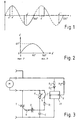
Ausführungsbeispiele der Erfindung sind in der Zeichnung dargestellt und werden in der nachfolgenden Beschreibung nach Aufbau und Wirkungsweise im einzelnen erläutert. Es zeigen:
- Fig. 1
- den zeitlichen Verlauf einer Verbraucher-Speisewechselspannung, wobei bei lückendem Betrieb durch die Phasenanschnittschaltung erkennbar ist, daß, wie in durchgezogener Linienführung gezeigt, der tatsächliche Zündwinkel in einer Vollwelle zu früh und in der nachfolgenden Vollwelle zu spät liegt, verglichen mit dem Sollwert des Zündwinkels α;
- Fig. 2
- den Verlauf des Differenzwinkels δ über dem Sollwert des Zündwinkels α und
- Fig. 3
- ein mögliches und auch bevorzugtes Ausführungsbeispiel einer Phasenanschnittschaltung in diskreten Bauelementen, zur Reduzierung des Oberwellenanteils bei elektrischen Verbrauchern.
- Fig. 1
- the time course of a consumer supply alternating voltage, whereby in the event of intermittent operation by the phase gating circuit it can be seen that, as shown in solid lines, the actual ignition angle is too early in a full wave and too late in the subsequent full wave, compared with the setpoint of the ignition angle α ;
- Fig. 2
- the course of the differential angle δ over the target value of the ignition angle α and
- Fig. 3
- a possible and also preferred embodiment of a phase control circuit in discrete components, for reducing the harmonic content in electrical consumers.
Betrachtet man zunächst den im Grundsatz sinusförmig im Verlauf beispielsweise einer Speisewechselspannung für einen elektrischen Verbraucher, dann läßt sich dem Diagramm der Fig. 1 entnehmen, daß an der ersten Vollwelle (siehe jeweils die dick durchgezogene Linienführung) ein kleinerer tatsächlicher Zündwinkel α' vorhanden ist, verglichen mit dem Zündwinkel α'' in der zweiten Vollwelle, die sich daher um den Differenzwinkel δ unterscheiden.If you first consider the sinusoidal principle in the Course, for example, of an alternating voltage for an electrical consumer, then the 1 that that on the first solid shaft (see the thick solid lines) a smaller actual ignition angle α 'is present is compared to the ignition angle α ″ in the second Full wave, which is therefore the difference angle δ differentiate.
Mit anderen Worten bedeutet dies, daß in der ersten Vollwelle bei kleinerem α' mit eher großer, eigentlich mit zu großer Leistung gefahren wird, während in der zweiten Vollwelle mit dem zu großen Zündwinkel α'' mit kleiner, und zwar zu kleiner Leistung gefahren wird, immer bezogen auf den tatsächlichen Leistungsanspruch, der durch den Sollwert-Zündwinkel α gegeben ist, der bei diesem Ausführungsbeispiel der Einfachheit halber bei 90° liegen soll und der natürlich selbst, z.B. durch äußeren Eingriff, wieder verstellbar ist.In other words, this means that in the first Solid wave with smaller α 'with rather large, actually is driven with too much power while in the second solid shaft with the ignition angle α '' too large smaller, and is driven at lower power, always in relation to the actual entitlement to benefits, which is given by the setpoint ignition angle α, which at this embodiment for the sake of simplicity at 90 ° should lie and of course itself, e.g. by external Intervention that is adjustable again.
Daher liegt bei diesem Ausführungsbeispiel der erste Zündwinkel α' bei 60° und der zweite Zündwinkel α'' bei 120°; der Differenzwinkel δ beträgt somit 60°.Therefore, the first is in this embodiment Firing angle α 'at 60 ° and the second firing angle α' 'at 120 °; the difference angle δ is thus 60 °.
Diese Variation oder Unsymmetrie des Zündwinkels in nacheinander ablaufenden Vollwellen (nicht notwendigerweise unmittelbar aufeinanderfolgender Vollwellen) der den Verbraucher speisenden Wechselspannungsgröße beruht auf der weiter vorn schon erwähnten Erkenntnis, daß dann, wenn eine solche Unsymmetrie des Zündwinkels nicht zwischen positiver und negativer Halbwelle einer Vollwelle, sondern zeitlich zwischen zwei aufeinanderfolgenden Wellen erzeugt wird, die geradzahligen Harmonischen langsam anwachsen und die ungeradezahligen stark reduziert werden. Dies kommt gerade der Leistungssteuerung bei einem Elektromotor entgegen, der von sich aus schon eher ungeradezahlige Harmonische erzeugt, die sich durch Schaltungen, wie eben schon erwähnt, natürlich nicht beeinflussen lassen. Insgesamt wird hierdurch aber durch die aufeinanderfolgenden Unsymmetrien der Zündwinkelverteilung in Abweichung vom Sollwert des Zündwinkels α der Gesamtoberwellengehalt soweit herabgesetzt, daß den Grenzwertbedingungen der erwähnten Vorschriften Genüge getan werden kann.This variation or asymmetry of the ignition angle in consecutive full waves (not necessarily consecutive full waves) based on the AC voltage supplying the consumer based on the knowledge already mentioned earlier that if such an asymmetry in the ignition angle is not between positive and negative half wave of a full wave, but between two consecutive times Waves is generated, the even harmonics grow slowly and the odd number is greatly reduced become. This just comes from power control with an electric motor, which in itself already rather odd harmonics generated by Circuits, as already mentioned, of course not be influenced. Overall, however, this will help the successive asymmetries of the ignition angle distribution in deviation from the target value of the ignition angle α Total harmonic content reduced so far that the Limit value conditions of the mentioned regulations are sufficient can be done.
Dabei ergibt sich natürlich keine Abweichung von dem
gewünschten Leistungsollwert des Verbrauchers, da die
tatsächlichen Zündwinkel α', α'' um den Sollwert des
Zündwinkels herum variieren, nämlich einmal nach der
einen und zum anderen nach der anderen Seite, also
sozusagen mit Vorzündung und mit Nachzündung arbeiten,
wobei der Zündwinkelversatz, also der Differenzwinkel δ
bevorzugt, z.B. bei einem angenommenen Sollwert des
Zündwinkels α von 90° maximal, beispielsweise 60°
betragen sollte, wie der Diagrammverlauf der Fig. 2
zeigt. Bei Annäherung an die maximale Leistung, d.h. je
kleiner der Sollwert des Zündwinkels α selbst wird und im
äußersten Fall bei einem Zündwinkel α von 0°, wenn gar
kein Phasenanschnitt mehr erfolgt, ist natürlich auch der
Differenzwinkel δ = 0. In diesem Fall wird die Zündwinkelvariation
aber auch nicht mehr benötigt, da durch die
Phasenanschnittschaltung im wesentlichen keine Oberwellen
mehr erzeugt werden. Gleiches trifft auf die Leistungsabgabe
0, also maximalen Sollwert des Zündwinkels α zu.
Auch in diesem Falle, wenn also der Reihentriac bei einem
bevorzugten Ausführungsbeispiel einer Phasenanschnittschaltung
gar nicht mehr öffnet, ist der Differenzwinkel
δ ebenfalls gleich Null (siehe hierzu den Kurvenverlauf
der Fig. 2).There is of course no deviation from that
desired power setpoint of the consumer, since the
actual ignition angle α ', α' 'around the setpoint of the
Ignition angle vary around, namely once after the
one and the other to the other, so
so to speak work with pre-ignition and with post-ignition,
where the ignition angle offset, ie the difference angle δ
preferred, e.g. with an assumed setpoint of
Ignition angle α of 90 ° maximum, for example 60 °
should be the same as the diagram of FIG. 2
shows. When approaching the maximum power, i.e. ever
the setpoint of the ignition angle α itself becomes smaller and in
extreme case with an ignition angle α of 0 °, if at all
of course no phase gating is done anymore
Difference angle δ = 0. In this case the ignition angle variation
but also no longer needed because of the
Gating circuit essentially no harmonics
be generated more. The same applies to the
Anschaulich läßt sich das durch die Erfindung gefundene Prinzip so verstehen, daß in der Vollwelle mit großem Zündwinkel (entsprechend kleiner Leistung) die dritte Harmonische klein und in der Phase zum Nulldurchgang hin verschoben ist. In der Vollwelle mit kleinem Zündwinkel (entsprechend großer Leistung) ist die dritte Harmonische zwar kräftig, jedoch in der Phase in umgekehrter Richtung verschoben, so daß sich die zwei dritten Harmonischen, die aus den beiden Vollwellen mit unterschiedlichem Zündwinkel von jeweils α' und α'' resultieren, zum Teil selbst aufheben können. Für die anderen Harmonischen können ähnliche Betrachtungen angestellt werden, die aber im Vergleich zur dritten Harmonischen weniger bis unbedeutend sind.The found by the invention can be clearly illustrated Understand the principle that in the full wave with large Firing angle (corresponding to small power) the third Small harmonics and in phase towards zero crossing is moved. In the solid shaft with a small ignition angle (correspondingly great performance) is the third harmonic vigorous, but in the reverse phase shifted so that the two third harmonics, those from the two solid waves with different Firing angles of α 'and α' 'result, in part can pick up yourself. For the other harmonics Similar considerations can be made, but compared to the third harmonic less to are insignificant.
An einem Versuchsaufbau mit einem Motor mit einer Leistung von 1200 W ergab sich bei einem Sollwert-Zündwinkel α von 90° eine ursprüngliche dritte Harmonische von 2,3 A. Durch einen Zündwinkelversatz von 45° jeweils nach vorn und nach hinten, d.h. beispielsweise von einem α' von 45° und einem α'' von 135° ergab sich eine Reduzierung dieser dritten Harmonischen von den erwähnten 2,3 A auf 1,5 A, wobei der Motor selbst unter voller Last eine dritte Harmonische von 1,3 A verursachte. Gleichzeitig wuchs die vierte Harmonische von ca. 50 mA auf 300 mA an, verblieb also selbst schon in diesem Bereich eher unbedeutend.On a test setup with an engine with a Power of 1200 W resulted at a setpoint ignition angle α of 90 ° an original third harmonic of 2.3 A. By an ignition angle offset of 45 ° forward and backward, i.e. for example an α 'of 45 ° and an α' 'of 135 ° resulted a reduction of this third harmonic from the mentioned 2.3 A to 1.5 A, the motor itself under a third harmonic of 1.3 A at full load. At the same time, the fourth harmonic grew from around 50 mA to 300 mA, so it already stayed there Area rather insignificant.
Diese Messungen verifizieren eine durchaus drastische Abnahme des Oberwellen-Gesamtgehalts allein durch die durch die Erfindung gewährleistete Zündwinkelvariation, die sich in einfacher Weise wie im folgenden beschrieben realisieren läßt. These measurements verify a very drastic one Decrease in the total harmonic content by the ignition angle variation guaranteed by the invention, which are simple as described below can be realized.
Entsprechend Fig. 3 sind als übliche Bestandteile einer Phasenanschnittsteuerung der Verbraucher M als Elektromotor und der in beiden Halbwellen leitend schaltbare Reihentriac zum Motor M mit T angegeben.3 are as usual components of a Phase control of the consumers M as an electric motor and the switchable in both half-waves Series triac to motor M indicated with T.
Im Ansteuerkreis des Motors befindet sich neben dem üblichen Kondensator C ein entsprechendes Reihenpotentiometer P, wobei vom Verbindungspunkt des Kondensators C und des Reihenpotentiometers P über einen Diac D und einen Reihenwiderstand R die Ansteuerung des Triac-Gates erfolgt.In the control circuit of the motor is next to the usual capacitor C a corresponding series potentiometer P, from the connection point of the capacitor C and the series potentiometer P via a diac D and a series resistor R the control of the triac gate he follows.
Parallel zum Widerstand des Potentiometers P ist ein weiterer Widerstand R1 geschaltet, der in Reihe mit einem Schalter S liegt, der im geschlossenen Zustand den parallelen Widerstand R1 zum Widerstandswert des Potentiometers P wirksam werden läßt bzw. im geöffneten Zustand herausschaltet.Parallel to the resistance of the potentiometer P is a further resistor R1 connected in series with one Switch S is located in the closed state parallel resistance R1 to the resistance value of the potentiometer P takes effect or in the open State switches out.
Angesteuert wird der Schalter S, der ein beliebiger elektronischer, vorzugsweise transistorisierter schneller Schalter sein kann, in diesem Falle von einem Flipflop FF, welches an seinem Eingang E über einen Widerstand R3 mit der halben Netzfrequenz periodisch umgeschaltet wird; die Speisung des Flipflops FF erfolgt über die Reihenschaltung eines Widerstandes R2 mit einer Diode D1.The switch S, which is any electronic, preferably transistorized faster Switch can be, in this case, a flip-flop FF, which at its input E via a resistor R3 is switched periodically at half the network frequency; the flip-flop FF is supplied via the series circuit a resistor R2 with a diode D1.
Wie bekannt erfolgt bei einer normalen Phasenanschnittsteuerung unabhängig von der Polarität und der Zeit bei einem bestimmten Winkel die Zündung des Triacs, wobei sich der Zündwinkel durch die Einstellung des Potentiometers verändern läßt. Durch die zusätzliche periodische Veränderung dieses Widerstands des Potentiometers P mit der halben Netzfrequenz (beim Ausführungsbeispiel also 25 Hz, wenn eine deutsche oder europäische Netzfrequenz von 50 Hz zugrunde gelegt wird) läßt sich erreichen, daß der Parallelwiderstand R1 in der einen Vollwelle bei geschlossenem Schalter dem leistungsstellenden Potentiometer P parallel liegt und in der nächsten Vollwelle bei geöffnetem Schalter wieder herausgeschaltet ist. Dies führt zu einer entsprechenden periodischen Änderung des Widerstandswerts des Potentiometers P und einer entsprechenden Verlagerung des Zündwinkels α zeitlich nach vorn oder hinten auf die Werte α' bzw. α" wie in Fig. 1 gezeigt, wodurch der gewünschte Zweck erreicht ist. Dabei wird das Flipflop FF durch die halbe Netzfrequenz im positiven Nulldurchgang getriggert.As is known, normal phase control takes place regardless of polarity and time the ignition of the triac at a certain angle, whereby the ignition angle by adjusting the potentiometer can change. Due to the additional periodic Change this resistance of the potentiometer P with half the network frequency (25 in the exemplary embodiment Hz if a German or European network frequency of 50 Hz is taken as the basis), it can be achieved that the Parallel resistance R1 in one solid wave when closed Switch the power potentiometer P is parallel and in the next solid wave open switch is switched off again. This leads to a corresponding periodic change of the Resistance value of the potentiometer P and a corresponding one Shift in the ignition angle α after front or rear to the values α 'or α "as in FIG. 1 shown, whereby the desired purpose is achieved. Here is the flip-flop FF by half the network frequency in positive zero crossing triggered.
Es wird nochmals darauf aufmerksam gemacht, daß die Erfindung durch dieses anhand der Zusammenstellung von diskreten Bauelementen erläuterte Ausführungsbeispiel einer Phasenanschnittschaltung nicht eingeschränkt oder der erfinderische Rahmen vorgegeben wird, sondern die Erfindung kann durch beliebige schaltungstechnische Maßnahmen realisiert werden und auch in hochintegrierter Form etwa anhand eines schnellen Mikroprozessors realisiert werden. Es ist auch möglich, jeweils auf den Anwendungszweck bezogen, eine größere Anzahl von Vollwellen mit einem vorgegebenen ersten Wert eines Zündwinkels α' zu steuern und erst nach Ablauf von einigen Vollwellen auf den zweiten, in der entgegengesetzten Richtung zum Sollwert des Zündwinkels versetzten Zündwinkel überzugehen, wobei empirische Versuche gut geeignet sind um festzustellen, ob und in welcher Weise der jeweils angesteuerte Verbraucher hierdurch beeinflußt wird, beispielsweise durch Änderung der von ihm abgegebenen Geräuschentwicklung, Flackern bei Lichtbänken u.dgl.. Es versteht sich auch, daß keine Beschränkung auf die jeweiligen vorhandenen oder von den Versorgungswerken zur Verfügung gestellten Netzfrequenzen erforderlich ist; nötigenfalls kann mit anderen Frequenzen, mit Frequenzverdoppelung u.dgl. gearbeitet werden, soweit sich dies als sinnvoll erweist, auch ein Bereich der Ansteuerung der Zeitkonstantenansteuerung für die Triac-Zündung. Hier könnte im übrigen auch mit jedem beliebigen, technisch noch sinnvollen zeitlichen Verteilungsmuster, gegebenenfalls auch stochastischer Natur, gearbeitet werden.Attention is once again drawn to the fact that the Invention by this based on the compilation of Discrete components illustrated embodiment a phase control circuit is not restricted or the inventive framework is given, but the Invention can by any circuitry Measures are implemented and also in highly integrated Form realized using a fast microprocessor become. It is also possible to refer to the Application-related, a larger number of solid shafts with a predetermined first value of an ignition angle To control α 'and only after some Full waves on the second, in the opposite Direction to the setpoint of the ignition angle offset ignition angle transition, with empirical trials well suited to determine if and how the each consumer controlled thereby affected is, for example, by changing the one he delivers Noise development, flickering in light banks and the like. It is also understood that there is no limitation to the respective existing or from the pension funds Provided network frequencies is required; if necessary, with other frequencies, with frequency doubling and the like be worked as far as this also proves to be sensible, an area of control the time constant control for the triac ignition. Here could, moreover, with any, technical still reasonable temporal distribution pattern, if necessary also of a stochastic nature.
Claims (8)
- A method of power control of electric consumers connected to an alternating-voltage supply mains, in particular electric motors, electric universal motors for operating electrical equipment, kitchen appliances, vacuum cleaners and the like, of resistive consumers such as electric heating or the like, by changing the phase angle of the electric alternating quantity supplied to the consumer, characterised in that to reduce the harmonic content, the firing angle (α', α") determining the extent of the phase angle is varied, in accordance with both larger and smaller values, with successive full waves around about the preset firing-angle rated value (α) corresponding to the desired power consumption, in such a manner that with a simultaneous slow increase in even harmonics, odd harmonics are greatly reduced.
- A method in accordance with Claim 1, characterised in that chronologically, asymmetry of the firing angle is produced between two immediately successive full waves.
- A method in accordance with Claim 1 or 2, characterised in that with a first full wave, the actual firing angle (α1) is smaller in both half waves as compared with the rated value of the firing angle (α), and with an immediately following full wave, the actual firing angle (α") is greater preferably by the same amount as compared with the set-value firing-angle (α), whereby in that the third harmonics produced by the phase-angle control itself at least partially cancel themselves out.
- A method in accordance with any one of Claims 1 to 3, characterised in that the actual firing angle variation in chronologically successive full waves is also carried out stochastically within a few full waves with a high probability of contrary developments.
- A device for power control of electric consumers connected to an alternating-voltage supply mains, in particular electric motors or electric universal motors for operating electrical equipment, kitchen appliances, vacuum cleaners, of resistive consumers such as electric heating and the like, a change in the operating angle of a triac (T) connected in series with the consumer and in the electric quantity supplied to the consumer being carried out by the power control, characterised in that a control circuit varying the actual firing angle (α', α") about the rated value (α) of the firing angle of the desired power consumption is provided and is such that within a few full waves, these preferably being immediately successive, the firing angle (α', α") is altered in accordance with both larger and smaller values.
- A device in accordance with Claim 5, different firing-angle signals being supplied to the triac per (immediately) successive full waves of the supply voltage to be connected to the consumer.
- A device in accordance with Claim 5 or 6, characterised in that a firing-angle control unit is associated with the triac (T) and with full waves - which are directly successive or are in close succession - of the electric alternating quantity feeding the consumer supplies actual firing-angle signals (α', α") to the triac, with a preset power output these signals being displaced chronologically ahead or behind as compared with the rated value of the firing angle (α) by preferably identical angular difference amounts.
- A device in accordance with Claim 7, characterised in that a bistable (flip-flop FF) connecting with the half mains-frequency is associated with the adjustable rheostat (potentiometer P) in the trigger circuit (potentiometer P and capacitor C) of the triac (T), which bistable in one full wave connects - by means of a switch (S) - a resistor (R1) of preset magnitude in parallel with the power-adjusting potentiometer (P) and in the next or in one of the following full waves disconnects it by opening the switch.
Applications Claiming Priority (4)
| Application Number | Priority Date | Filing Date | Title |
|---|---|---|---|
| DE1997202524 DE29702524U1 (en) | 1997-02-14 | 1997-02-14 | Device for power control of electrical consumers connected to an AC supply network |
| DE1997105907 DE19705907C2 (en) | 1997-02-14 | 1997-02-14 | Method and device for power control of electrical consumers connected to an AC supply network |
| DE19705907 | 1997-02-14 | ||
| DE29702524U | 1997-02-14 |
Publications (2)
| Publication Number | Publication Date |
|---|---|
| EP0859452A1 EP0859452A1 (en) | 1998-08-19 |
| EP0859452B1 true EP0859452B1 (en) | 1999-11-03 |
Family
ID=26033976
Family Applications (1)
| Application Number | Title | Priority Date | Filing Date |
|---|---|---|---|
| EP19980101787 Expired - Lifetime EP0859452B1 (en) | 1997-02-14 | 1998-02-03 | Method and device for power control of electric consumers connected to an alternating voltage supply network |
Country Status (7)
| Country | Link |
|---|---|
| US (1) | US5955794A (en) |
| EP (1) | EP0859452B1 (en) |
| JP (1) | JP3636420B2 (en) |
| KR (1) | KR100500719B1 (en) |
| AU (1) | AU725876B2 (en) |
| DE (1) | DE59800041D1 (en) |
| TR (1) | TR199800216A3 (en) |
Cited By (2)
| Publication number | Priority date | Publication date | Assignee | Title |
|---|---|---|---|---|
| DE10357918B3 (en) * | 2003-12-11 | 2005-03-17 | Kurz, Gerhard | Phase-chopping power regulator for electric motor has semiconductor switch in series with latter and second semiconductor switch connected in series with resistance element across first semiconductor switch |
| DE102009035964A1 (en) | 2009-08-04 | 2011-02-10 | Miele & Cie. Kg | Method and control device for power control of a vacuum cleaner and vacuum cleaner with such a control device |
Families Citing this family (15)
| Publication number | Priority date | Publication date | Assignee | Title |
|---|---|---|---|---|
| ES2157813B1 (en) * | 1999-07-28 | 2002-03-01 | Remco S L | CURRENT CONSUMPTION REDUCTION SYSTEM IN HARMONICS OF THE NETWORK FREQUENCY IN POWER REGULATORS BASED ON THE TRIGGER ANGLE CONTROL. |
| US6614197B2 (en) | 2001-06-30 | 2003-09-02 | Motorola, Inc. | Odd harmonics reduction of phase angle controlled loads |
| DE10220779A1 (en) * | 2002-05-10 | 2003-11-27 | Bosch Gmbh Robert | Method of running an electric motor e.g. for control servos in motor vehicle, requires varying the frequency and phases of current flow independently of rotor speed for noise reduction |
| US7397225B2 (en) | 2002-08-14 | 2008-07-08 | Gerhard Kurz | Apparatus for controlling the power of an AC voltage supplying an electrical consumer by phase control and method for reducing harmonics |
| US7936576B2 (en) * | 2003-09-05 | 2011-05-03 | Nxp B.V. | Power controller |
| US7342372B2 (en) * | 2005-10-05 | 2008-03-11 | Aktiebolaget Electrolux | Method for power control of an electric motor |
| DE102007035954A1 (en) * | 2007-07-30 | 2009-02-05 | Royal Appliance International Gmbh | Electric consumer's e.g. high voltage incandescent lamp, power regulating method for alternating current network, involves selecting phase angles of phase section of half-waves, where finite number of angles is uneven or greater than one |
| DE102007055718A1 (en) * | 2007-12-06 | 2009-06-10 | Robert Bosch Gmbh | power tool |
| FR2956189B1 (en) * | 2010-02-11 | 2012-03-02 | Fagorbrandt Sas | SUCTION HOOD AND CONTROL METHOD THEREFOR |
| KR20160028232A (en) * | 2014-09-03 | 2016-03-11 | 삼성전자주식회사 | image forming apparatus and phase control method |
| TWI597930B (en) * | 2015-02-06 | 2017-09-01 | Use to change the conduction angle as the control command of the control device | |
| JP6562955B2 (en) * | 2017-02-23 | 2019-08-21 | 株式会社志賀機能水研究所 | Harmonic generator |
| KR102041395B1 (en) * | 2018-05-09 | 2019-11-27 | 주창희 | Compression type cooling control system, and compressor type cooling control method using the same |
| CN111082512A (en) * | 2019-12-23 | 2020-04-28 | 广州市科士达电源设备有限公司 | Intelligent precise power distribution cabinet |
| CN112510713B (en) * | 2021-02-03 | 2021-04-20 | 中国测试技术研究院电子研究所 | Harmonic control method and control device |
Family Cites Families (12)
| Publication number | Priority date | Publication date | Assignee | Title |
|---|---|---|---|---|
| GB1449600A (en) * | 1972-12-15 | 1976-09-15 | Nat Res Dev | Methods and apparatus for speed control of induction motors |
| US3863134A (en) * | 1973-07-23 | 1975-01-28 | Gen Electric | Electric control circuits for a static power converter |
| US4078168A (en) * | 1976-09-17 | 1978-03-07 | Flinn & Dreffein Engineering Company | Power control circuit |
| DE2702142C3 (en) * | 1977-01-20 | 1979-08-02 | Robert Bosch Gmbh, 7000 Stuttgart | Arrangement for controlling the speed of a universal motor |
| DE2856574A1 (en) * | 1978-12-28 | 1980-07-17 | Loher Gmbh | ARRANGEMENT FOR ADJUSTING THE SPEED OF AN INDUCTION MACHINE |
| DE3303126A1 (en) * | 1983-01-31 | 1984-08-09 | Gerhard 7262 Althengstett Kurz | Device for limiting the switching-on current of loads which are operated with an AC voltage |
| GB8304016D0 (en) * | 1983-02-14 | 1983-03-16 | Ass Elect Ind | Firing-angle control in inverters |
| US4811236A (en) * | 1986-11-03 | 1989-03-07 | Westinghouse Electric Corp. | Transmission line voltage detector for static VAR generator |
| CA1289190C (en) * | 1986-12-05 | 1991-09-17 | Tomoharu Nakamura | Static var compensator |
| US4763059A (en) * | 1987-06-23 | 1988-08-09 | General Electric Company | Method and apparatus for induction motor drive |
| ES2071730T3 (en) * | 1990-12-10 | 1995-07-01 | Asea Brown Boveri | PROCEDURE AND DEVICE FOR THE ELIMINATION OR REDUCTION OF HARMONICS AND / OR OF RESONANCE OSCILLATIONS. |
| DE19536148A1 (en) * | 1995-09-28 | 1997-04-03 | Wilo Gmbh | Control of speed or drive torque of induction or universal motors for heat circulation pumps |
-
1997
- 1997-07-14 US US08/892,043 patent/US5955794A/en not_active Expired - Fee Related
-
1998
- 1998-02-03 EP EP19980101787 patent/EP0859452B1/en not_active Expired - Lifetime
- 1998-02-03 DE DE59800041T patent/DE59800041D1/en not_active Expired - Fee Related
- 1998-02-11 KR KR10-1998-0003923A patent/KR100500719B1/en not_active IP Right Cessation
- 1998-02-12 TR TR1998/00216A patent/TR199800216A3/en unknown
- 1998-02-13 AU AU53936/98A patent/AU725876B2/en not_active Ceased
- 1998-02-16 JP JP3267698A patent/JP3636420B2/en not_active Expired - Fee Related
Cited By (3)
| Publication number | Priority date | Publication date | Assignee | Title |
|---|---|---|---|---|
| DE10357918B3 (en) * | 2003-12-11 | 2005-03-17 | Kurz, Gerhard | Phase-chopping power regulator for electric motor has semiconductor switch in series with latter and second semiconductor switch connected in series with resistance element across first semiconductor switch |
| DE102009035964A1 (en) | 2009-08-04 | 2011-02-10 | Miele & Cie. Kg | Method and control device for power control of a vacuum cleaner and vacuum cleaner with such a control device |
| EP2302778A1 (en) | 2009-08-04 | 2011-03-30 | Miele & Cie. KG | Method and control device for controlling the output of a vacuum cleaner and vacuum cleaner with such a control device |
Also Published As
| Publication number | Publication date |
|---|---|
| AU5393698A (en) | 1998-08-20 |
| EP0859452A1 (en) | 1998-08-19 |
| US5955794A (en) | 1999-09-21 |
| KR19980071244A (en) | 1998-10-26 |
| JP3636420B2 (en) | 2005-04-06 |
| DE59800041D1 (en) | 1999-12-09 |
| KR100500719B1 (en) | 2005-10-26 |
| TR199800216A2 (en) | 1998-09-21 |
| AU725876B2 (en) | 2000-10-26 |
| TR199800216A3 (en) | 1998-09-21 |
| JPH10271891A (en) | 1998-10-09 |
Similar Documents
| Publication | Publication Date | Title |
|---|---|---|
| EP0859452B1 (en) | Method and device for power control of electric consumers connected to an alternating voltage supply network | |
| EP2178201B1 (en) | Method and control system for transforming an AC voltage into a consumer supply voltage with adjustable rms value | |
| DE2305251B2 (en) | EXCITATION DEVICE FOR A SELF-EXCITED ASYNCHRONOUS GENERATOR | |
| DE2225609C2 (en) | Arrangement for controlling the speed of a multiphase alternating current asynchronous motor fed via a static converter with variable voltage and, for example, with proportional frequency | |
| DE3015196C2 (en) | Method and arrangement for operating an AC motor at a standstill | |
| CH675510A5 (en) | ||
| EP0353569A2 (en) | Method to avoid AC instabilities in a negative mains supply inverter for a converter with an intermediate DC circuit in case of a dynamic voltage drop, and circuit arrangement for carrying out the method | |
| CH631297A5 (en) | METHOD FOR PRODUCING IN A CONTROLLED RECTIFIER CIRCUIT OF ONE OF THE REQUIRED CONTROL VOLTAGE PROPORTIONAL OUTPUT CURRENTS. | |
| DE3708071A1 (en) | ENERGY SUPPLY DEVICE, ESPECIALLY FOR A GAS DISCHARGE DEVICE | |
| DE4442151A1 (en) | Circuit arrangement for controlling an electronically commutated motor | |
| EP0379608B1 (en) | Method and device for controlling single or multiphase ac voltage converters | |
| DE3032293A1 (en) | INVERTER-MOTOR COMPOUND WITH DIFFERENT CONTROL CHARACTERISTICS FOR INVERTER VOLTAGE AND FREQUENCY | |
| DE3230206A1 (en) | CONTROL DEVICE FOR RECTIFIERS | |
| DE2553629C3 (en) | Arrangement for keeping the speed of an AC motor constant | |
| DE4201005C2 (en) | Circuit arrangement for mains-independent, misfire-free braking of a series motor | |
| DE3015108C2 (en) | Method and arrangement for controlling an AC motor by means of an inverter | |
| DE19705907C2 (en) | Method and device for power control of electrical consumers connected to an AC supply network | |
| DE102005036802B3 (en) | Method and device for increasing the efficiency of an electric motor | |
| CH623436A5 (en) | ||
| DE3800753C2 (en) | Method for the master control of semiconductor switches of a regenerative rectifier and arrangement for carrying out the method | |
| DE19802711C2 (en) | Power reduction of a double turbine in vacuum cleaners | |
| DE4107431C2 (en) | ||
| DE3034501C2 (en) | Regulated regenerative DC voltage supply | |
| DE1613776B2 (en) | PROCEDURE FOR THE SPEED AND VOLTAGE CONTROL OF AN AC MOTOR IN PARTICULAR THREE-PHASE AC MOTORS | |
| DE2703284A1 (en) | Smooth starting circuit for electric motors - has switch in motor circuit shunted by RC element and current source circuit |
Legal Events
| Date | Code | Title | Description |
|---|---|---|---|
| PUAI | Public reference made under article 153(3) epc to a published international application that has entered the european phase |
Free format text: ORIGINAL CODE: 0009012 |
|
| AK | Designated contracting states |
Kind code of ref document: A1 Designated state(s): DE FR IT SE |
|
| AX | Request for extension of the european patent |
Free format text: AL;LT;LV;MK;RO;SI |
|
| 17P | Request for examination filed |
Effective date: 19981030 |
|
| GRAG | Despatch of communication of intention to grant |
Free format text: ORIGINAL CODE: EPIDOS AGRA |
|
| 17Q | First examination report despatched |
Effective date: 19990127 |
|
| GRAG | Despatch of communication of intention to grant |
Free format text: ORIGINAL CODE: EPIDOS AGRA |
|
| GRAH | Despatch of communication of intention to grant a patent |
Free format text: ORIGINAL CODE: EPIDOS IGRA |
|
| AKX | Designation fees paid |
Free format text: DE FR IT SE |
|
| RBV | Designated contracting states (corrected) |
Designated state(s): DE FR IT SE |
|
| GRAH | Despatch of communication of intention to grant a patent |
Free format text: ORIGINAL CODE: EPIDOS IGRA |
|
| GRAH | Despatch of communication of intention to grant a patent |
Free format text: ORIGINAL CODE: EPIDOS IGRA |
|
| GRAA | (expected) grant |
Free format text: ORIGINAL CODE: 0009210 |
|
| AK | Designated contracting states |
Kind code of ref document: B1 Designated state(s): DE FR IT SE |
|
| REF | Corresponds to: |
Ref document number: 59800041 Country of ref document: DE Date of ref document: 19991209 |
|
| ITF | It: translation for a ep patent filed |
Owner name: BARZANO' E ZANARDO MILANO S.P.A. |
|
| ET | Fr: translation filed | ||
| PLBE | No opposition filed within time limit |
Free format text: ORIGINAL CODE: 0009261 |
|
| STAA | Information on the status of an ep patent application or granted ep patent |
Free format text: STATUS: NO OPPOSITION FILED WITHIN TIME LIMIT |
|
| 26N | No opposition filed | ||
| PGFP | Annual fee paid to national office [announced via postgrant information from national office to epo] |
Ref country code: DE Payment date: 20090226 Year of fee payment: 12 |
|
| PGFP | Annual fee paid to national office [announced via postgrant information from national office to epo] |
Ref country code: SE Payment date: 20090223 Year of fee payment: 12 Ref country code: IT Payment date: 20090227 Year of fee payment: 12 |
|
| PGFP | Annual fee paid to national office [announced via postgrant information from national office to epo] |
Ref country code: FR Payment date: 20090217 Year of fee payment: 12 |
|
| EUG | Se: european patent has lapsed | ||
| REG | Reference to a national code |
Ref country code: FR Ref legal event code: ST Effective date: 20101029 |
|
| PG25 | Lapsed in a contracting state [announced via postgrant information from national office to epo] |
Ref country code: FR Free format text: LAPSE BECAUSE OF NON-PAYMENT OF DUE FEES Effective date: 20100301 |
|
| PG25 | Lapsed in a contracting state [announced via postgrant information from national office to epo] |
Ref country code: DE Free format text: LAPSE BECAUSE OF NON-PAYMENT OF DUE FEES Effective date: 20100901 |
|
| PG25 | Lapsed in a contracting state [announced via postgrant information from national office to epo] |
Ref country code: IT Free format text: LAPSE BECAUSE OF NON-PAYMENT OF DUE FEES Effective date: 20100203 |
|
| PG25 | Lapsed in a contracting state [announced via postgrant information from national office to epo] |
Ref country code: SE Free format text: LAPSE BECAUSE OF NON-PAYMENT OF DUE FEES Effective date: 20100204 |