EP0678633B1 - Building made of several separate prefabricated concrete elements absorbing thermal energy - Google Patents
Building made of several separate prefabricated concrete elements absorbing thermal energy Download PDFInfo
- Publication number
- EP0678633B1 EP0678633B1 EP94115551A EP94115551A EP0678633B1 EP 0678633 B1 EP0678633 B1 EP 0678633B1 EP 94115551 A EP94115551 A EP 94115551A EP 94115551 A EP94115551 A EP 94115551A EP 0678633 B1 EP0678633 B1 EP 0678633B1
- Authority
- EP
- European Patent Office
- Prior art keywords
- precast concrete
- structure according
- heat
- acting
- pipes
- Prior art date
- Legal status (The legal status is an assumption and is not a legal conclusion. Google has not performed a legal analysis and makes no representation as to the accuracy of the status listed.)
- Expired - Lifetime
Links
Images

Classifications
-
- F—MECHANICAL ENGINEERING; LIGHTING; HEATING; WEAPONS; BLASTING
- F24—HEATING; RANGES; VENTILATING
- F24T—GEOTHERMAL COLLECTORS; GEOTHERMAL SYSTEMS
- F24T10/00—Geothermal collectors
- F24T10/10—Geothermal collectors with circulation of working fluids through underground channels, the working fluids not coming into direct contact with the ground
- F24T10/13—Geothermal collectors with circulation of working fluids through underground channels, the working fluids not coming into direct contact with the ground using tube assemblies suitable for insertion into boreholes in the ground, e.g. geothermal probes
- F24T10/17—Geothermal collectors with circulation of working fluids through underground channels, the working fluids not coming into direct contact with the ground using tube assemblies suitable for insertion into boreholes in the ground, e.g. geothermal probes using tubes closed at one end, i.e. return-type tubes
-
- Y—GENERAL TAGGING OF NEW TECHNOLOGICAL DEVELOPMENTS; GENERAL TAGGING OF CROSS-SECTIONAL TECHNOLOGIES SPANNING OVER SEVERAL SECTIONS OF THE IPC; TECHNICAL SUBJECTS COVERED BY FORMER USPC CROSS-REFERENCE ART COLLECTIONS [XRACs] AND DIGESTS
- Y02—TECHNOLOGIES OR APPLICATIONS FOR MITIGATION OR ADAPTATION AGAINST CLIMATE CHANGE
- Y02B—CLIMATE CHANGE MITIGATION TECHNOLOGIES RELATED TO BUILDINGS, e.g. HOUSING, HOUSE APPLIANCES OR RELATED END-USER APPLICATIONS
- Y02B10/00—Integration of renewable energy sources in buildings
- Y02B10/20—Solar thermal
-
- Y—GENERAL TAGGING OF NEW TECHNOLOGICAL DEVELOPMENTS; GENERAL TAGGING OF CROSS-SECTIONAL TECHNOLOGIES SPANNING OVER SEVERAL SECTIONS OF THE IPC; TECHNICAL SUBJECTS COVERED BY FORMER USPC CROSS-REFERENCE ART COLLECTIONS [XRACs] AND DIGESTS
- Y02—TECHNOLOGIES OR APPLICATIONS FOR MITIGATION OR ADAPTATION AGAINST CLIMATE CHANGE
- Y02E—REDUCTION OF GREENHOUSE GAS [GHG] EMISSIONS, RELATED TO ENERGY GENERATION, TRANSMISSION OR DISTRIBUTION
- Y02E10/00—Energy generation through renewable energy sources
- Y02E10/10—Geothermal energy
Definitions
- the invention relates to a building that consists of several separate, each - embedded as a heat energy absorber Tubes for a liquid containing energy carrier and possibly plate-like interconnected Precast concrete is made that is radial on a central axis to a columnar or multi-rib construction are composed, at least partially at a distance run to each other and with a base part of their heat extraction surface are located underground.
- a building of this type is the applicant's EP-A-0442432 refer to.
- To produce absorber plates, some of which under the Lawn surface are arranged and solve the task for the smallest possible free space outside a building to offer a solid absorber that is also installed can be all technical and economic Prerequisites fulfilled, not disturbing and if possible to take on one or more additional functions be able to.
- WO-A-90 00 707 describes an energy exchanger which via an isolating flow line with one in one Well connected pump connected as well as both in the well are surrounded by a protective tube open at the bottom which extends radially outwards to the borehole wall Return area for return water connects.
- WO-A-81 00 445 are solar collectors in the form of with - also double-layered - embedded concrete slabs disclosed that integrated into buildings or these can be assigned as garden walls.
- the inventor was aware of this state of the art set the goal, the application of such Building in the smallest possible space and the Improve heat balance if possible.
- the building is laid in the ground Pipes at least one assigned to the outside of the building Heat exchange device connected as a trench collector.
- Bauwerk are precast concrete slabs with integrated Pipes attached to the base of the building in the floor become.
- the preliminary runs to the building are preferred appended and the returns to one assigned to it known distributor connected.
- Trench collectors such as concrete slabs are presented as Thermal energy absorber when erecting the building in the Construction pit and connects them in the manner already mentioned the pipe coil system of the building.
- This structure should also be preferred in each of its slabs one - in two each one of the plate surface nearby levels arranged - meandering bent coil be embedded from 80 to 120 m in length; as the most economical
- the size of an absorber circuit is one Absorber circuit pipe coil from 120 to 160 m.
- the concrete absorber has to take up between 80 and 120 running meters (running meters) of pipe length. At a coverage of from 7 lfdm m per m 2 results in a two-dimensional absorber size 12 to 20 m 2. Since the heat of the outside air can be extracted from both surfaces in a free-standing prefabricated part - absorber pipes can be concreted in on both sides - the result is an average prefabricated part in the size of 6 m 2 to 10 m 2 .
- a concrete absorber measuring 1 x 6 m fulfills these requirements for the absorber circuit.
- This structure can accommodate, for example, plant scaffolds, which give it a particularly favorable appearance, but can also be used to accommodate plants that are particularly in need of heat.
- At least one absorber circuit is also conceivable here the building to a shower, a sprinkler or the like. To connect dispensing elements.
- more than three absorber circuit concrete elements basically as a cross or in the form of a star assembled into a garden column.
- the amount of this Garden column above soil is under four meters and their Digging depth limited to around 2.50 m, and the elements are spaced above ground so that flushing with air and wind is facilitated.
- the structure described is used as an energy pillar, can even be used for the monovalent heating of a family home be used if at least two more the absorber elements to be assigned according to the invention in addition to come.
- This pillar of energy takes less than three meters in diameter in the floor plan, so they can be set up on almost any property.
- the column can also be planted in a summer Operating fountains, fountain fountains, too a shower system, a water tap or to one Seat etc. can be added.
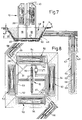
- a columnar structure 10 has four of FIG a cruciform plan indicated in FIG Plates 12, two of which are connected to each other are aligned, the mutually facing inner edges 14 above the grown soil to each other at a distance a of, for example Run 80 cm.
- Each of the plates 12 with a height h of, for example, 600 cm, a width b of, for example, 140 cm and a thickness i from 14 to 22 cm is at a distance e of about 200 cm to the underside of the plate 16 with a - from a ridge line 17 inclined towards both sides 18 - shoulder-like Provided paragraph 20 of length f of about 40 cm from on the one hand that inner edge 14 and on the other hand one from shoulder-like paragraph 20 downward narrow side 22 going out. The latter delimits a base part on the side 23 of plate 12.
- Both the narrow side 24 and the - also narrow - Outside 24 and the ridge side 26 of the plate 12 are chamfered on both sides so that from a cross-sectional Tip a bow edge 28 is formed.
- the corner is broken between outside 24 and ridge side 26 at 30.
- a rectangular recess surface 34 provided, which ends at the inner edge 14.
- an absorber circuit consisting of a pipe coil 36 is embedded, which extends from a flow 37 to a return 38.
- the distance k of the parallel pipe sections of the pipe coil 36 is approximately 10 cm from one another, and, according to FIG. 6, the pipe coil 34 extends in two mutually parallel planes F 1 , F 2 .
- a distributor 39 is provided on which the individual Circles combined on the supply and forwarding side are and from which manifolds to one for reasons neglected the clarity in the drawing Lead heat pump.
- the lower plate section or base part 23 is embedded in the ground at a digging depth e 1 .
- B denotes the upper edge of the earth, above which the plates 12 of the structure 10 are connected to one another by base strips 40.
- the base parts 23 of the plates 12 are connected to one another by angle brackets 42.
- Fig. 7 at 60 is a borehole with a so-called geothermal probe 62 outlined; run in a backfill 64 up to a tube door deepest 66 probe tubes 68.69, through the probe tube 68 serving as a riser pipe passes heat-transporting pipe Brine to building 10 - in Fig. 8 this is Riser pipe 68 connected to a supply 52 of a plate 50, however, there is also a direct connection to the Pipe coil 36 of the building 10 is conceivable. So is the underground even at greater depths, energy than heating or cooling capacity withdrawn and used the situation, a deep area to tap into in which without major interference a relatively constant surface Temperature prevails.
- the brine flows through the coil 36 to the respective Plate 12 connected to borehole 60 to distributor 39 and from this through the downpipe 69 back to the deepest tube door 66 back.
- the construction described extends the possible uses of such structures 10 significantly and improves Stabilization of heat generation significantly.
Landscapes
- Engineering & Computer Science (AREA)
- Life Sciences & Earth Sciences (AREA)
- General Life Sciences & Earth Sciences (AREA)
- Sustainable Development (AREA)
- Sustainable Energy (AREA)
- Chemical & Material Sciences (AREA)
- Combustion & Propulsion (AREA)
- Mechanical Engineering (AREA)
- General Engineering & Computer Science (AREA)
- Building Environments (AREA)
- Devices For Post-Treatments, Processing, Supply, Discharge, And Other Processes (AREA)
- Buildings Adapted To Withstand Abnormal External Influences (AREA)
Abstract
Description
Die Erfindung betrifft ein Bauwerk, das aus mehreren gesonderten, jeweils -- als Wärmeenergieabsorber wirkenden --eingebetteten Rohren für eine Energieträgerflüssigkeit enthaltende und gegebenenfalls miteinander verbundene plattenartige Betonfertigteile besteht, die radial an einer Mittelachse zu einer säulenartigen oder mehrrippigen Konstruktion zusammengesetzt sind, zumindest teilweise in Abstand zueinander verlaufen sowie mit einem Sockelteil ihrer Wärmeentzugsfläche unterirdisch angeordnet sind.The invention relates to a building that consists of several separate, each - embedded as a heat energy absorber Tubes for a liquid containing energy carrier and possibly plate-like interconnected Precast concrete is made that is radial on a central axis to a columnar or multi-rib construction are composed, at least partially at a distance run to each other and with a base part of their heat extraction surface are located underground.
Ein Bauwerk dieser Art ist der EP-A-0442432 der Anmelderin zu entnehmen. Ausgehend von Massivabsorbersystemen in Außenwänden von Hochbauten zur Wärmeenergiegewinnung, wird dort vorgeschlagen, kreuz- oder sternförmige Bauwerke aus Absorberplatten herzustellen, welche teilweise unter der Rasenoberfläche angeordnet sind und die Aufgabe lösen, für einen möglichst kleinen freien Platz außerhalb eines Gebäudes einen Massivabsorber anzubieten, der zusätzlich aufgestellt werden kann, alle technischen und wirtschaftlichen Voraussetzungen erfüllt, nicht störend wirkt und nach Möglichkeit eine oder mehrere weitere Funktion zu übernehmen in der Lage ist.A building of this type is the applicant's EP-A-0442432 refer to. Starting from solid absorber systems in External walls of high-rise buildings for heat energy generation proposed there, cross or star-shaped structures To produce absorber plates, some of which under the Lawn surface are arranged and solve the task for the smallest possible free space outside a building to offer a solid absorber that is also installed can be all technical and economic Prerequisites fulfilled, not disturbing and if possible to take on one or more additional functions be able to.
Die WO-A-90 00 707 beschreibt einen Energietauscher, der über eine isolierende Vorlaufleitung mit einer in einem Bohrloch angeordneten Pumpe verbunden sowie beide im Bohrloch von einem unten offenen Schutzrohr umgeben sind, an das sich radial nach außen bis zur Bohrlochwandung ein Rücklaufbereich für Rücklaufwasser anschließt. Dieser enthält eine poröse Füllung, steht am Bohrlochtiefsten mit der Pumpe in Verbindung, und in ihn mündet eine Rücklaufleitung des Energietauschers, die im Bohrloch mindestens ein bis annähernd an das Bohrlochtiefste reichendes Rücklaufrohr aufweist, das mehrere über seine Länge verteilte Querverschlüsse sowie beidseits davon angeordnete Durchtrittsöffnungen enthält sowie in die poröse Füllung in jenem Rücklaufbereich eingebettet ist.WO-A-90 00 707 describes an energy exchanger which via an isolating flow line with one in one Well connected pump connected as well as both in the well are surrounded by a protective tube open at the bottom which extends radially outwards to the borehole wall Return area for return water connects. This contains a porous filling, is the deepest with the Pump in connection, and a return line opens into it of the energy exchanger, which is at least one to return pipe reaching almost down to the borehole which has several cross closures distributed over its length and passage openings arranged on both sides thereof contains as well as in the porous filling in that return area is embedded.
In der WO-A-81 00 445 sind Solarkollektoren in Form von mit -- auch doppellagig -- eingebetteten Rohren versehenen Betonplatten offenbart, die in Gebäude integriert oder diesen als Gartenmauern zugeordnet werden.In WO-A-81 00 445 are solar collectors in the form of with - also double-layered - embedded concrete slabs disclosed that integrated into buildings or these can be assigned as garden walls.
Bekannt ist zudem aus der CH-PS 674 045 ein Fundierungs- und Absicherungselement aus Beton als Wärmespeicher für den Anschluß an ein Heizsystem.A foundation and is also known from CH-PS 674 045 Protection element made of concrete as heat storage for the Connection to a heating system.
In Kenntnis dieses Standes der Technik hat sich der Erfinder das Ziel gesetzt, die Einsatzmöglichkeit eines solchen Bauwerkes auf möglichst kleinstem Raum zu erhöhen und die Wärmebilanz nach Möglichkeit zu verbessern.The inventor was aware of this state of the art set the goal, the application of such Building in the smallest possible space and the Improve heat balance if possible.
Zur Lösung dieser Aufgabe führt die Lehre des unabhängigen Patentanspruches; die abhängigen Patentansprüche geben günstige Fortentwicklungen an.The teaching of the independent leads to the solution of this task Claim; the dependent claims give favorable Further developments.
Erfindungsgemäß werden an das Bauwerk im Boden verlegte Rohre wenigstens eine außerhalb des Bauwerkes diesem zugeordnete Wärmetauscheinrichtung als Grabenkollektor angeschlossen. Besonders günstig als Zusatz für das erfindungsgemäße Bauwerk sind Betonfertigplatten mit integrierten Rohren, die im Boden dem Sockelteil des Bauwerkes angefügt werden. Dabei sind die Vorläufe bevorzugt an das Bauwerk angefügt und die Rückläufe an einen diesem zugeordneten, an sich bekannten Verteiler angeschlossen.According to the invention, the building is laid in the ground Pipes at least one assigned to the outside of the building Heat exchange device connected as a trench collector. Particularly favorable as an additive for the invention Bauwerk are precast concrete slabs with integrated Pipes attached to the base of the building in the floor become. The preliminary runs to the building are preferred appended and the returns to one assigned to it known distributor connected.
Derartige Grabenkollektoren wie Betonplatten stellt man als Wärmeenergieabsorber beim Errichten des Bauwerkes in die Baugrube und schließt sie in der bereits erwähnten Art an das Rohrschlangensystem des Bauwerkes an. Vorteilhafterweise wird man diese zusätzlichen Betonfertigplatten an die geneigten Böschungswände der Baugruppe legen und dann letztere mit dem üblichen Hinterfüllmaterial schließen. Bevorzugt soll jeder im Bauwerk enthaltenen flügelartigen Platte eine solche Betonfertigplatte im Boden zugeordnet und diese an die Rohrschlange der jeweiligen Bauwerksplatte angeschlossen werden.Trench collectors such as concrete slabs are presented as Thermal energy absorber when erecting the building in the Construction pit and connects them in the manner already mentioned the pipe coil system of the building. Advantageously one will attach these additional precast concrete slabs to the and then slope the slope walls of the assembly close the latter with the usual backfill material. Prefers Everyone should be wing-like contained in the building Such a precast concrete slab is assigned in the floor and this to the coil of the respective building slab be connected.
Im Rahmen der Erfindung liegt es aber auch, in einem -- wie gesagt, der WO-A-90 00 707 entnehmbaren -- Bohrloch eine zusätzliche wärmeträgerführende Rohrtour anzubringen, welche mit ihrem Steigrohr an das Bauwerk angeschlossen ist und zwar bevorzugt in der für die Betonfertigplatten beschriebenen Weise. Die vom Bohrlochtiefsten aufsteigende Sole fällt nach dem Durchgang durch Bauwerk und Verteiler im Fallrohr wieder ab.However, it is also within the scope of the invention in one - how said from WO-A-90 00 707 - borehole one to install additional pipe tour carrying heat transfer medium, which is connected to the building with its riser pipe and preferably in that described for the precast concrete slabs Wise. The ascending from the deepest hole Brine falls after passing through the structure and distributor in the downpipe.
Auch bei diesem Bauwerk soll bevorzugt in jede seiner Platten eine -- in zwei jeweils einer der Plattenoberfläche nahen Ebenen angeordnete -- mäanderartig gebogene Rohrschlange von 80 bis 120 m Länge eingebettet sein; als wirtschaftlichste Größe eines Absorberkreises stellt sich eine Absorberkreis-Rohrschlange von 120 bis 160 m dar. This structure should also be preferred in each of its slabs one - in two each one of the plate surface nearby levels arranged - meandering bent coil be embedded from 80 to 120 m in length; as the most economical The size of an absorber circuit is one Absorber circuit pipe coil from 120 to 160 m.
Geht man von etwa 20 m für die Zuleitung und 20 m für die
Rückführung der Absorberkreis-Rohrlänge aus, hat der Betonabsorber
zwischen 80 und 120 laufende Meter (lfdm) Rohrlänge
aufzunmehmen. Bei einer Belegungsdichte von 7 lfdm m
je m2 ergibt sich eine flächige Absorbergröße zwischen 12
und 20 m2. Da bei einem freistehenden flächigem Fertigteil
von beiden Flächen Wärme der Außenluft entziehbar ist
-- also an beiden Flächenseiten Absorberrohre einbetoniert
werden können --, ergibt sich im Mittel ein Fertigteil in
der Größe von 6 m2 bis 10 m2. So erfüllt etwa ein Betonabsorber
in den Abmessungen 1 m x 6 m diese Voraussetzungen
für den Absorberkreis. Dieses Bauwerk vermag beispielsweise
Pflanzengerüste aufzunehmen, die ihm ein besonders günstiges
Aussehen verleihen, darüber hinaus aber auch der Aufnahme
besonders wärmebedürftiger Pflanzen zu dienen vermögen.Assuming about 20 m for the supply line and 20 m for the return of the absorber circle pipe length, the concrete absorber has to take up between 80 and 120 running meters (running meters) of pipe length. At a coverage of from 7 lfdm m per m 2 results in a two-
Denkbar ist es aber auch hier wenigstens einen Absorberkreislauf des Bauwerks an eine Dusche, eine Berieselungseinrichtung od. dgl. Abgabeelemente anzuschließen.However, at least one absorber circuit is also conceivable here the building to a shower, a sprinkler or the like. To connect dispensing elements.
Vorteilhafterweise werden mehr als drei Absorberkreis-Betonelemente grundrißlich als Kreuz oder in Form eines Sternes zu einer Gartensäule zusammengestellt. Die Höhe dieser Gartensäule über Erdreich wird auf unter vier Meter und deren Eingrabtiefe auf rund 2,50 m begrenzt, und die Elemente werden oberirdisch im Abstand zueinander angeordnet, damit eine Umspülung mit Luft und Wind erleichtert wird.Advantageously, more than three absorber circuit concrete elements basically as a cross or in the form of a star assembled into a garden column. The amount of this Garden column above soil is under four meters and their Digging depth limited to around 2.50 m, and the elements are spaced above ground so that flushing with air and wind is facilitated.
Das beschriebene Bauwerk wird als Energiesäule eingesetzt, kann jedoch sogar für die monovalente Heizung eines Einfamilienhauses herangezogen werden, wenn mindestens zwei weitere der erfindungsgemäß zuzuordnenden Absorberelemente ergänzend hinzukommen. Diese Energiesäule nimmt weniger als drei Meter Durchmesser im Grundriß in Anspruch, so daß sie auf nahezu jedem Grundstück aufstellbar ist. The structure described is used as an energy pillar, can even be used for the monovalent heating of a family home be used if at least two more the absorber elements to be assigned according to the invention in addition to come. This pillar of energy takes less than three meters in diameter in the floor plan, so they can be set up on almost any property.
Außer zu einem Stützgerüst für Blumenkästen oder für rankende Pflanzen kann die Säule auch zu einem im Sommer in Betrieb befindlichen Springbrunnen, Fontainenbrunnen, zu einer Duschanlage, einer Wasserzapfstelle oder zu einem Sitzplatz etc. ergänzt werden. Except for a support frame for flower boxes or for climbing The column can also be planted in a summer Operating fountains, fountain fountains, too a shower system, a water tap or to one Seat etc. can be added.
Weitere Vorteile, Merkmale und Einzelheiten der Erfindung ergeben sich aus der nachfolgenden Beschreibung bevorzugter Ausführungsbeispiele sowie anhand der Zeichnung; diese zeigt in:
- Fig. 1:
- eine Schrägsicht auf ein aus Platten bestehendes säulenartiges Bauwerk;
- Fig. 2:
- den Grundriß zu Fig. 1;
- Fig. 3:
- die Seitenansicht einer Platte des Bauwerkes;
- Fig. 4:
- eine Stirnansicht der Platte der Bauwerkes;
- Fig. 5:
- die Seitenansicht gemäß Fig. 3 mit einem Rohrschlangensystem;
- Fig. 6:
- einen Teil der Fig. 5 in Stirnansicht,
- Fig. 7:
- eine Seitenansicht des Bauwerkes mit im Boden vorgesehenen Bauwerksteilen in schematischem Längsschnitt;
- Fig. 8:
- die Draufsicht auf einen Teil der Fig. 7.
- Fig. 1:
- an oblique view of a columnar structure consisting of plates;
- Fig. 2:
- the floor plan of Fig. 1;
- Fig. 3:
- the side view of a plate of the building;
- Fig. 4:
- an end view of the plate of the building;
- Fig. 5:
- the side view of Figure 3 with a coil system.
- Fig. 6:
- part of FIG. 5 in front view,
- Fig. 7:
- a side view of the building with structural parts provided in the floor in a schematic longitudinal section;
- Fig. 8:
- the top view of part of FIG. 7th
Ein säulenartiges Bauwerk 10 weist gemäß Fig. 1 vier von
einem in Fig. 2 angedeuteten kreuzförmigen Grundriß aufragende
Platten 12 auf, von denen jeweils zwei miteinander
fluchten, deren einander zugekehrte Innenkanten 14 über dem
gewachsenen Boden zueinander in einem Abstand a von beispielsweise
80 cm verlaufen.A
Jede der Platten 12 einer Höhe h von beispielsweise 600 cm,
einer Breite b von beispielsweise 140 cm sowie einer Dicke
i von 14 bis 22 cm ist in einem Abstand e von etwa 200 cm
zur Plattenunterseite 16 mit einem -- von einer Kammlinie
17 zu beiden Seitenflächen 18 hin geneigten -- schulterartigen
Absatz 20 der Länge f von etwa 40 cm versehen, von
dem einerseits jene Innenkante 14 und anderseits eine vom
schulterartigen Absatz 20 nach unten verlaufende Schmalseite
22 ausgehen. Letztere begrenzt seitlich einen Sockelteil
23 der Platte 12.Each of the
Sowohl die Schmalseite 24 als auch die -- ebenfalls schmale
-- Außenseite 24 und die Firstseite 26 der Platte 12 sind
beidseits so angefast, daß von einer querschnittlichen
Spitze eine Bugkante 28 gebildet wird. Zudem ist die Ecke
zwischen Außenseite 24 und Firstseite 26 bei 30 gebrochen.Both the
Im oberen Teil der Platte 12 ist eine rechteckige Vertiefungsfläche
34 vorgesehen, die an der Innenkante 14 endet.In the upper part of the
In den Beton der Platte 12 ist ein Absorkerkreislauf aus
einer Rohrschlange 36 eingebettet, der sich von einem Vorlauf
37 zu einem Rücklauf 38 erstreckt. Der Abstand k der
parallelen Rohrabschnitte der Rohrschlange 36 voneinander
beträgt etwa 10 cm, zudem verläuft gemäß Fig. 6 die Rohrschlange
34 in zwei zueinander parallelen Ebenen F1,F2.In the concrete of the
Innerhalb eines den Grundriß in Fig. 2 umschreibenden Kreises
Q ist ein Verteiler 39 vorgesehen, an dem die einzelnen
Kreise zuleitungs- und fortleitungsseitig zusammengefaßt
sind und von dem aus Sammelleitungen zu einer aus Gründen
der Übersichtlichkeit in der Zeichnung vernachlässigten
Wärmepumpe führen.Within a circle circumscribing the floor plan in FIG. 2
Q is a
Der untere Plattenabschnitt oder Sockelteil 23 ist in einer
Eingrabtiefe e1 in das Erdreich eingelassen. Mit B ist die
Erdreichoberkante bezeichnet, oberhalb deren die Platten 12
des Bauwerkes 10 durch Sockelstreifen 40 miteinander verbunden
sind. Die Sockelteile 23 der Platten 12 werden durch
Winkellaschen 42 aneinandergeschlossen. The lower plate section or
Um das entsprechend Fig. 7 auf einer Frostschutzschicht
unter Zwischenschaltung eines Sandbettes 47 auf dem Grunde
einer Baugrube 48 mit in einem Winkel w geneigten Böschungswänden
49 auflastende Bauwerk 12 sind auf diese Böschungswände
49 weitere als Wärmeenergieabsorber ausgebildete
Platten 50 in einem Abstand e2 zur Erdreichoberkante B
von etwa 70 cm gelegt. Vorlauf 52 und Rücklauf 53 der Absorberkreisläufe
oder Rohrschlangen 54 dieser Platten 50
sind an die entsprechenden Leitungen 37 bzw. 38 des Bauwerks
10 angeschlossen. Der Vorlauf 52 jeder der Platten in
Fig. 8 führt zum benachbart aufragenden Sockelteil 23, dessen
Vorlauf 37 am Verteiler 39 endet. Ebenfalls führen die
Rückläufe 53 der Platten 50 zum Verteiler 39. Die im Erdreich
liegenden Absorberplatten 50 entziehen dem Boden
Wärme, und so kann ein weiterer Kreis von Wärmetauschern
über das Bauwerk 10 an den Verteiler 39 -- und damit an die
Energieversorgung eines nicht dargestellten Gebäudes -- angeschlossen
werden.7 on a frost protection layer with the interposition of a
In Fig. 7 ist bei 60 ein Bohrloch mit einer sog. Erdwärmesonde
62 skizziert; in einer Hinterfüllung 64 verlaufen
bis zu einem Rohrtourtiefsten 66 Sondenrohre 68,69, durch
das als Steigrohr diendende Sondenrohr 68 gelangt wärmetransportierende
Sole zum Bauwerk 10 - in Fig. 8 ist dieses
Steigrohr 68 an einen Vorlauf 52 einer Platte 50 angeschlossen,
jedoch ist auch ein direkter Anschluß an die
Rohrschlange 36 des Bauwerks 10 denkbar. So wird dem Untergrund
auch in größerer Teufe Energie als Wärme- oder Kälteleistung
entzogen und die Gegebenheit genutzt, einen Teufenbereich
zu erschließen, in welchem ohne größere Beeinflussung
von der Oberfläche her eine verhältnismäßig konstante
Temperatur herrscht.In Fig. 7 at 60 is a borehole with a so-called
Die Sole strömt durch die Rohrschlange 36 der an das jeweilige
Bohrloch 60 angeschlossenen Platte 12 zum Verteiler 39
und von diesem durch das Fallrohr 69 wieder zum Rohrtourtiefsten
66 zurück. The brine flows through the
Die beschriebene Konstruktion erweitert die Einsatzmöglichkeiten
derartiger Bauwerke 10 erheblich und verbessert die
Stabilisierung der Wärmeerzeugung erheblich.The construction described extends the possible uses
of
Claims (8)
- Structure (10) consisting of a plurality of separate precast concrete elements (12) in the form of panels each containing embedded pipes for an energy transfer fluid acting as thermal energy absorbers and possibly connected together, said precast concrete elements being assembled radially along a centre axis to form a columnar or multiple-rib construction, extending at least partially at a distance from one another and being arranged with a base part (23) of their heat-absorption surfaces underground, characterised in that underground (48) pipes (54) of least one outside heat exchanger (50) associated with the structure acting as trench collectors for ground heat are connected to the structure (10).
- Structure according to claim 1, characterised in that the pipes (54) are embedded in a precast concrete panel (50) acting as a thermal energy absorber and the latter is associated with the base part (18) of the structure (10).
- Structure according to claim 2, characterised in that several of the precast concrete panels (50) are associated with the structure (10) at an incline relative to its bottom plane (46).
- Structure according to claim 2 or claim 3, with a base part (23) provided in a pit (48) or similar excavation, characterised in that several precast concrete panels (50) are provided at an incline on the slope walls (49) of the pit (48), one precast concrete panel acting as a thermal energy absorber preferably being associated with each panel (12) of the structure (10).
- Structure according to one of claims 1 to 4, characterised in that the flow pipes (37) of the associated heat exchangers (50) are connected to the structure (10) and the return pipes (38) are connected to a distributor (39).
- Structure according to one of claims 1 to 5, characterised by an associated heat transfer fluid-conducting string (68, 90) in a bore hole (60) acting as an additional heat exchanger (62).
- Structure according to claim 6, characterised in that the ascending section (68) of the string is connected to a distributor (39) and/or the structure (10).
- Structure according to claim 6 or claim 7, characterised in that the descending section (69) of the string is connected to the distributor (39) and runs to the bottom (66) of the bore hole.
Applications Claiming Priority (2)
| Application Number | Priority Date | Filing Date | Title |
|---|---|---|---|
| DE4410689A DE4410689A1 (en) | 1994-03-28 | 1994-03-28 | Structure from several separate precast concrete parts |
| DE4410689 | 1994-03-28 |
Publications (3)
| Publication Number | Publication Date |
|---|---|
| EP0678633A2 EP0678633A2 (en) | 1995-10-25 |
| EP0678633A3 EP0678633A3 (en) | 1997-01-29 |
| EP0678633B1 true EP0678633B1 (en) | 2000-03-22 |
Family
ID=6514032
Family Applications (1)
| Application Number | Title | Priority Date | Filing Date |
|---|---|---|---|
| EP94115551A Expired - Lifetime EP0678633B1 (en) | 1994-03-28 | 1994-10-04 | Building made of several separate prefabricated concrete elements absorbing thermal energy |
Country Status (3)
| Country | Link |
|---|---|
| EP (1) | EP0678633B1 (en) |
| AT (1) | ATE191037T1 (en) |
| DE (2) | DE4410689A1 (en) |
Cited By (1)
| Publication number | Priority date | Publication date | Assignee | Title |
|---|---|---|---|---|
| EP4357718A1 (en) | 2022-10-17 | 2024-04-24 | Thomas Friedrich | Solid absorber for heating and cooling purposes in buildings |
Families Citing this family (2)
| Publication number | Priority date | Publication date | Assignee | Title |
|---|---|---|---|---|
| DE202012004408U1 (en) * | 2012-04-27 | 2013-08-01 | Sachsenkinder Regionalmarketing Gmbh | Massive absorber in modular design |
| DE102019001010B3 (en) | 2019-02-08 | 2020-06-04 | Synergetiker GmbH | Surface absorber for a heat pump system |
Family Cites Families (5)
| Publication number | Priority date | Publication date | Assignee | Title |
|---|---|---|---|---|
| WO1981000445A1 (en) * | 1979-08-13 | 1981-02-19 | A Alosi | Concrete solar collectors |
| DE3247620C2 (en) * | 1982-12-23 | 1986-06-05 | Reinhold 7925 Dischingen Heckel | Arrangement for heat pumps |
| DE8520976U1 (en) * | 1985-07-20 | 1985-10-10 | Betonbau GmbH, 6833 Waghäusel | Transportable garage |
| EP0386176B1 (en) * | 1988-07-08 | 1992-01-02 | HILDEBRAND, Hans | Installation for energy exchange between the ground and an energy exchanger |
| DE4004666A1 (en) * | 1990-02-15 | 1991-08-29 | Betonbau Gmbh | CONSTRUCTION OF PRE-CONCRETE PARTS |
-
1994
- 1994-03-28 DE DE4410689A patent/DE4410689A1/en not_active Withdrawn
- 1994-10-04 DE DE59409234T patent/DE59409234D1/en not_active Expired - Fee Related
- 1994-10-04 EP EP94115551A patent/EP0678633B1/en not_active Expired - Lifetime
- 1994-10-04 AT AT94115551T patent/ATE191037T1/en not_active IP Right Cessation
Cited By (1)
| Publication number | Priority date | Publication date | Assignee | Title |
|---|---|---|---|---|
| EP4357718A1 (en) | 2022-10-17 | 2024-04-24 | Thomas Friedrich | Solid absorber for heating and cooling purposes in buildings |
Also Published As
| Publication number | Publication date |
|---|---|
| ATE191037T1 (en) | 2000-04-15 |
| EP0678633A3 (en) | 1997-01-29 |
| DE4410689A1 (en) | 1995-10-05 |
| DE59409234D1 (en) | 2000-04-27 |
| EP0678633A2 (en) | 1995-10-25 |
Similar Documents
| Publication | Publication Date | Title |
|---|---|---|
| DE102018110833A1 (en) | Charging station for electric vehicles with a roof comprising solar modules | |
| DE2707944A1 (en) | PROCESS FOR THE PRODUCTION OF MOISTURE-PROOF OR MOISTURE-RESISTANT FOUNDATION INSULATION FOR HOUSES OR OTHER BUILDINGS AND FOUNDATION INSULATION USED FOR IT | |
| DE3600230C2 (en) | ||
| EP0442432B1 (en) | Construction made of precast concrete elements | |
| AT391506B (en) | DEVICE FOR EXHAUSTING HEAT IN THE GROUND FLOOR OR TO RECOVER HEAT FROM THE GROUND FLOOR | |
| EP0678633B1 (en) | Building made of several separate prefabricated concrete elements absorbing thermal energy | |
| EP0076455B1 (en) | Solar plant | |
| EP2826925B1 (en) | Building complex | |
| EP0209833A1 (en) | Movable building unit | |
| EP0056797B1 (en) | Process of building heat store in the ground and heat store | |
| DE202008003472U1 (en) | Arrangement of at least one solar collector and a ground foundation | |
| EP0130178A2 (en) | Noise, wind or view barrier or protective structure for the banks of brooks and rivers | |
| DE2260087A1 (en) | COOLING TOWER WITH FILLING INSERT | |
| DE19856633A1 (en) | EWTS geothermal heat exchangers, system for using near-surface thermal storage systems | |
| DE102019005807A1 (en) | Plate-shaped insulating element | |
| DE4229185A1 (en) | Gathering energy from heat stored in ground - circulating heat transfer medium through closed circuit beneath ground to extract stored heat for driving turbine etc. | |
| DE202012004408U1 (en) | Massive absorber in modular design | |
| DE102011111704B3 (en) | Earth collector system, method of control and method of erection | |
| DE4322980A1 (en) | Power station, prefabricated unit of the power station, and method of manufacturing it | |
| DE102005053364B4 (en) | Geothermal heat exchanger and arrangement of geothermal heat exchangers | |
| DE2916637A1 (en) | Plant growth and noise screen system - has troughs supporting vegetation and conveying noise to humus underneath | |
| DE102021105079A1 (en) | Retention arrangement and structure with a retention arrangement | |
| EP0617172A2 (en) | Vegetative noise protection wall | |
| DE10112334A1 (en) | Building for commercial and domestic use comprises a body having a walled-in space and a device for rotating and/or pivoting the whole body | |
| DE3623824C2 (en) | Attachment to a building from a kit |
Legal Events
| Date | Code | Title | Description |
|---|---|---|---|
| PUAI | Public reference made under article 153(3) epc to a published international application that has entered the european phase |
Free format text: ORIGINAL CODE: 0009012 |
|
| AK | Designated contracting states |
Kind code of ref document: A2 Designated state(s): AT CH DE FR IT LI |
|
| RAX | Requested extension states of the european patent have changed |
Free format text: SI |
|
| RBV | Designated contracting states (corrected) |
Designated state(s): AT CH DE FR IT LI |
|
| PUAL | Search report despatched |
Free format text: ORIGINAL CODE: 0009013 |
|
| AK | Designated contracting states |
Kind code of ref document: A3 Designated state(s): AT CH DE FR IT LI |
|
| AX | Request for extension of the european patent |
Free format text: SI |
|
| 17P | Request for examination filed |
Effective date: 19970322 |
|
| 17Q | First examination report despatched |
Effective date: 19981218 |
|
| GRAG | Despatch of communication of intention to grant |
Free format text: ORIGINAL CODE: EPIDOS AGRA |
|
| GRAG | Despatch of communication of intention to grant |
Free format text: ORIGINAL CODE: EPIDOS AGRA |
|
| GRAH | Despatch of communication of intention to grant a patent |
Free format text: ORIGINAL CODE: EPIDOS IGRA |
|
| GRAH | Despatch of communication of intention to grant a patent |
Free format text: ORIGINAL CODE: EPIDOS IGRA |
|
| GRAA | (expected) grant |
Free format text: ORIGINAL CODE: 0009210 |
|
| DAX | Request for extension of the european patent (deleted) | ||
| AK | Designated contracting states |
Kind code of ref document: B1 Designated state(s): AT CH DE FR IT LI |
|
| PG25 | Lapsed in a contracting state [announced via postgrant information from national office to epo] |
Ref country code: IT Free format text: LAPSE BECAUSE OF FAILURE TO SUBMIT A TRANSLATION OF THE DESCRIPTION OR TO PAY THE FEE WITHIN THE PRE;WARNING: LAPSES OF ITALIAN PATENTS WITH EFFECTIVE DATE BEFORE 2007 MAY HAVE OCCURRED AT ANY TIME BEFORE 2007. THE CORRECT EFFECTIVE DATE MAY BE DIFFERENT FROM THE ONE RECORDED.SCRIBED TIME-LIMIT Effective date: 20000322 Ref country code: FR Free format text: THE PATENT HAS BEEN ANNULLED BY A DECISION OF A NATIONAL AUTHORITY Effective date: 20000322 |
|
| REF | Corresponds to: |
Ref document number: 191037 Country of ref document: AT Date of ref document: 20000415 Kind code of ref document: T |
|
| REG | Reference to a national code |
Ref country code: CH Ref legal event code: EP |
|
| REF | Corresponds to: |
Ref document number: 59409234 Country of ref document: DE Date of ref document: 20000427 |
|
| REG | Reference to a national code |
Ref country code: CH Ref legal event code: NV Representative=s name: HIEBSCH & PEEGE AG PATENTANWAELTE |
|
| ET | Fr: translation filed | ||
| PG25 | Lapsed in a contracting state [announced via postgrant information from national office to epo] |
Ref country code: AT Free format text: LAPSE BECAUSE OF NON-PAYMENT OF DUE FEES Effective date: 20001004 |
|
| PLBE | No opposition filed within time limit |
Free format text: ORIGINAL CODE: 0009261 |
|
| STAA | Information on the status of an ep patent application or granted ep patent |
Free format text: STATUS: NO OPPOSITION FILED WITHIN TIME LIMIT |
|
| 26N | No opposition filed | ||
| PGFP | Annual fee paid to national office [announced via postgrant information from national office to epo] |
Ref country code: CH Payment date: 20011102 Year of fee payment: 8 |
|
| REG | Reference to a national code |
Ref country code: FR Ref legal event code: ST |
|
| PG25 | Lapsed in a contracting state [announced via postgrant information from national office to epo] |
Ref country code: LI Free format text: LAPSE BECAUSE OF NON-PAYMENT OF DUE FEES Effective date: 20021031 Ref country code: CH Free format text: LAPSE BECAUSE OF NON-PAYMENT OF DUE FEES Effective date: 20021031 |
|
| REG | Reference to a national code |
Ref country code: CH Ref legal event code: PL |
|
| PGFP | Annual fee paid to national office [announced via postgrant information from national office to epo] |
Ref country code: DE Payment date: 20031029 Year of fee payment: 10 |
|
| PG25 | Lapsed in a contracting state [announced via postgrant information from national office to epo] |
Ref country code: DE Free format text: LAPSE BECAUSE OF NON-PAYMENT OF DUE FEES Effective date: 20050503 |