EP0678427A2 - Belt tensioner - Google Patents
Belt tensioner Download PDFInfo
- Publication number
- EP0678427A2 EP0678427A2 EP95105035A EP95105035A EP0678427A2 EP 0678427 A2 EP0678427 A2 EP 0678427A2 EP 95105035 A EP95105035 A EP 95105035A EP 95105035 A EP95105035 A EP 95105035A EP 0678427 A2 EP0678427 A2 EP 0678427A2
- Authority
- EP
- European Patent Office
- Prior art keywords
- hub
- belt
- pressure
- wall
- radial piston
- Prior art date
- Legal status (The legal status is an assumption and is not a legal conclusion. Google has not performed a legal analysis and makes no representation as to the accuracy of the status listed.)
- Granted
Links
Images

Classifications
-
- B—PERFORMING OPERATIONS; TRANSPORTING
- B60—VEHICLES IN GENERAL
- B60R—VEHICLES, VEHICLE FITTINGS, OR VEHICLE PARTS, NOT OTHERWISE PROVIDED FOR
- B60R22/00—Safety belts or body harnesses in vehicles
- B60R22/34—Belt retractors, e.g. reels
- B60R22/46—Reels with means to tension the belt in an emergency by forced winding up
- B60R22/4628—Reels with means to tension the belt in an emergency by forced winding up characterised by fluid actuators, e.g. pyrotechnic gas generators
Landscapes
- Engineering & Computer Science (AREA)
- Mechanical Engineering (AREA)
- Automotive Seat Belt Assembly (AREA)
- Devices For Conveying Motion By Means Of Endless Flexible Members (AREA)
Abstract
Description
Die Erfindung betrifft einen Gurtstraffer bei Sicherheitsgurtanordnungen in Kraftfahrzeugen nach den Oberbegriffen der Patentansprüche 1 und 4.The invention relates to a belt tensioner in seat belt arrangements in motor vehicles according to the preambles of claims 1 and 4.
Da die Rückzugskraft eines mit einer Rückzugsfeder ausgestatteten Gurtaufrollmechanismus aus Komfortgründen sehr gering ist und im allgemeinen nur zwischen 2 und 22 N beträgt, liegen von dem Insassen eines Fahrzeuges angelegte Sicherheitsgurte im allgemeinen nur relativ lose an dessen Körper an. Trägt der Insasse zudem noch eine voluminösere Kleidung, beispielsweise einen dicken Mantel, ist nicht mehr gewährleistet, daß der Sicherheitsgurt bei einem Unfall ausreichend straff am Körper des Benutzers anliegt. Aus diesem Grunde besteht ein Bedürfnis, den Gurt beim Auftreten eines Unfalles schlagartig so zu straffen, daß der Insasse sicher und ohne großes Spiel vom Gurtsystem festgehalten wird.Since the retraction force of a belt retraction mechanism equipped with a retraction spring is very low for reasons of comfort and is generally only between 2 and 22 N, seat belts worn by the occupant of a vehicle are generally only relatively loosely attached to the body. If the occupant also wears a more voluminous clothing, for example a thick coat, it is no longer guaranteed that the seat belt is sufficiently tight against the user's body in the event of an accident. For this reason, there is a need to suddenly tighten the belt when an accident occurs so that the occupant is held securely and without much play by the belt system.
Daher sind Gurtstrafferanordnungen erforderlich, die den Gurt bei einem Unfall mit einer hohen Kraft über einen hinreichenden Weg straffen. Sie sollen gleichzeitig jedoch kompakt und preiswert sowie nach einer unfallbedingten Straffung lösbar sein, so daS der Gurt nach einem kleineren Unfall beispielsweise für die Fahrt des Wagens zu einer Werkstatt noch angelegt werden kann.Therefore, pretensioner arrangements are required which tighten the belt over a sufficient distance in the event of a high-force accident. However, at the same time, they should be compact and inexpensive and releasable after an accident-related tightening, so that the belt can still be put on after a minor accident, for example for driving the car to a workshop.
Es ist schon bekannt (DE-OS 42 21 398), das am Chassis befestigte Gurtschloß bei einem Unfall durch eine Straffervorrichtung schlagartig um ein gewisses Stück in Richtung des Fahrzeugchassis zu bewegen, um so die für ein enges Anliegen des Sicherheitsgurtes am Körper des Insassen erforderliche Gurtverkürzung herbeizuführen. Weiter sind bereits Gurtstraffer bekannt, die üblicherweise pyrotechnische Treibladungen vewenden, um die Gurtrolle zur Straffung des Gurtes zu drehen. Die bekannten Straffer haben jedoch insbesondere den Nachteil, entweder nur über einen kurzen Weg zu straffen (EP-0 059 643 B1, DE-25 05 626 A1, US-A-24 77 907) oder sie sind nicht ausreichend kompakt (DE 35 31 856 A1).It is already known (DE-OS 42 21 398), the belt buckle attached to the chassis in an accident by a tensioning device to move suddenly a certain distance in the direction of the vehicle chassis, so that the necessary for a tight fit of the seat belt on the body of the occupant To shorten the belt. Belt tensioners are also known, usually Use pyrotechnic propellant charges to turn the belt reel to tighten the belt. However, the known tensioners in particular have the disadvantage of either only tightening over a short distance (EP-0 059 643 B1, DE-25 05 626 A1, US-A-24 77 907) or they are not sufficiently compact (
Gurtstraffer nach den Oberbegriffen der Ansprüche 1 und 4 sind bereits aus der EP 0 581 288 A1 bekannt.Belt tensioners according to the preambles of claims 1 and 4 are already known from EP 0 581 288 A1.
Ein generelles Problem bei dieser Gattung von Gurtstraffern besteht darin, daß der Winkelbewegungsbereich der Nabe dadurch begrenzt ist, daß das Dichtmittel im Falle der Auslösung der pyrotechnischen Ladung nur etwas weniger als eine ganze Umdrehung ausführen kann. Bei einer zu geringen Winkelbewegung der Nabe kann aber der erforderliche Straffereffekt am Sicherheitsgurt nicht mehr im erwünschten Ausmaß erzielt werden.A general problem with this type of belt tensioner is that the angular range of movement of the hub is limited by the fact that the sealant can only carry out a little less than a complete revolution if the pyrotechnic charge is triggered. If the angular movement of the hub is too small, the required pretensioning effect on the seat belt can no longer be achieved to the desired extent.
Das Ziel der vorliegenden Erfindung besteht darin, einen Gurtstraffer nach den Oberbegriffen der Ansprüche 1 oder 4 zu schaffen, bei welchem die den Gurtaufrollmechanismus beaufschlagende Nabe im Falle der Auslösung der pyrotechnischen Ladung einen größeren Drehwinkelbereich als etwas weniger als 360° zurücklegen kann.The aim of the present invention is to provide a belt tensioner according to the preambles of claims 1 or 4, in which the hub acting on the belt retraction mechanism can cover a larger angle of rotation range than slightly less than 360 ° in the event of the pyrotechnic charge being triggered.
Nach einer ersten Ausführungsform wird diese Aufgabe durch die Merkmale des kennzeichnenden Teils des Anspruches 1 gelöst. Eine vorteilhafte Weiterbildung dieser Ausführungsform entnimmt man Anspruch 2.According to a first embodiment, this object is achieved by the features of the characterizing part of claim 1. An advantageous further development of this embodiment can be found in claim 2.
Der Grundgedanke dieser Ausführungsform der Erfindung besteht darin, daß die Druckwand beweglich ausgebildet ist, derart, daß sie sich beim Umlaufen des Radialkolbens in gleicher Drehrichtung, jedoch mit geringerer Drehgeschwindigkeit verschiebt. Wenn der Radialkolben einen ganzen Umlauf zurückgelegt hat, ist die Druckwand je nach den Durchmessern der einzelnen Zahnräder bereits um ein erhebliches Winkelstück weiter gewandert, so daß auch der Radialkolben weiter um die Achse der Anordnung umlaufen kann, bevor er schließlich an die in Umfangsrichtung bewegliche Druckwand, die als frei bewegliches Planetenzahnrad ausgebildet ist, von hinten anstößt.The basic idea of this embodiment of the invention is that the pressure wall is designed to be movable in such a way that it moves in the same direction of rotation but at a lower rotational speed when the radial piston rotates. When the radial piston has covered an entire revolution, the pressure wall is already one, depending on the diameter of the individual gear wheels considerable elbow hiked further, so that the radial piston can continue to rotate around the axis of the arrangement, before finally hitting the circumferentially movable pressure wall, which is designed as a freely movable planetary gear, from behind.
Durch geeignete Durchmesserwahl für die einzelnen Zahnräder bzw. Zahnkränze können so Winkelbewegungen des Radialkolbens verwirklicht werden, wie sie im Anspruch 3 definiert sind.By suitable choice of diameter for the individual gears or ring gears, angular movements of the radial piston can be realized as defined in claim 3.
Eine weitere Ausführungsform der Erfindung ist durch die Merkmale des kennzeichnenden Teils des Anspruches 4 definiert. Eine vorteilhafte Weiterbildung dieses Ausführungsbeispiels ist im Anspruch 5 angegeben.Another embodiment of the invention is defined by the features of the characterizing part of claim 4. An advantageous further development of this exemplary embodiment is specified in claim 5.
Das Wesen dieser Ausführungsform besteht darin, daß das Außenzahnrad, das Ritzel und die außenverzahnte Nabe ein kompaktes Übersetzungsgetriebe bilden, wobei die Durchmesserverhältnisse so gewählt werden können, daß die Nabe deutlich mehr als eine ganze Umdrehung ausführen kann, obwohl der Radialkolben wegen des in diesem Fall in Umfangsrichtung feststehenden Ritzels nur einen Drehwinkel von weniger als 360° überstreichen kann.The essence of this embodiment is that the external gear, the pinion and the externally toothed hub form a compact transmission gear, whereby the diameter ratios can be chosen so that the hub can make significantly more than an entire revolution, although the radial piston because of the in this case in the circumferential direction pinion can only sweep an angle of rotation of less than 360 °.
Auf diese Weise ist es ohne weiteres möglich, für die Nabe einen Drehwinkelbereich nach Anspruch 6 zu erzielen.In this way it is easily possible to achieve a rotation angle range for the hub according to claim 6.
Die Erfindung wird im folgenden beispielsweise anhand der Zeichnung beschrieben; in dieser zeigt
- Figur 1
- eine schematische, teilweise geschnittene und auseinandergezogene perspektivische Ansicht einer ersten Ausführungsform des erfindungsgemäßen Gurtstraffers,
- Figur 2
- eine Ansicht des Gegenstandes der Fig. 1 in Richtung des Pfeiles II in zusammengebautem Zustand,
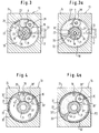
- Figur 3
- eine vergrößerte, senkrecht zur Drehbahn geschnittene Darstellung des Antriebes des Gurtstraffers nach der Figur 1 und 2 bei Beginn einer Auslösung,
- Figur 3a
- die gleiche Schnittdarstellung wie Figur 3, jedoch bei einer fortgeschrittenen Winkelbewegung des Radialkolbens,
- Figur 4
- eine vergrößerte, senkrecht zur Drehachse geschnittene Darstellung einer weiteren Ausführungsform für den Antrieb des Gurtstraffers nach den Figuren 1 und 2 bei Beginn einer Auslösung und
- Figur 4a
- die gleiche Schnittansicht wie Figur 4 bei einer fortgeschrittenen Winkelbewegung des Radialkolbens.
- Figure 1
- 2 shows a schematic, partially sectioned and exploded perspective view of a first embodiment of the belt tensioner according to the invention,
- Figure 2
- 1 in the assembled state,
- Figure 3
- 2 shows an enlarged illustration of the drive of the belt tensioner according to FIGS. 1 and 2, cut perpendicular to the rotating path, at the start of a release,
- Figure 3a
- 3 shows the same sectional view as FIG. 3, but with an advanced angular movement of the radial piston,
- Figure 4
- an enlarged, perpendicular to the axis of rotation shown representation of a further embodiment for driving the belt tensioner according to Figures 1 and 2 at the start of a trigger and
- Figure 4a
- the same sectional view as Figure 4 with an advanced angular movement of the radial piston.
Nach den Figuren 1 und 2 ist ein Gurtaufrollmechanismus 12 mittels einer Halterung 36 am Chassis 11 eines Kraftfahrzeuges befestigt. Der Gurtaufrollmechanismus 12 weist eine Gurtrolle 25 auf, auf welche mittels einer an einem Ende der Halterung 36 angeordneten Spiralfederanordnung 29 ein Sicherheitsgurt 16 soweit aufgerollt werden kann, daß er mit einer Zugkraft zwischen 2 und 22 N am Körper eines Insassen, der den Sicherheitsgurt 16 angelegt hat, zur Anlage kommt.According to FIGS. 1 and 2, a
An der von der Spiralfederanordnung 29 abgewandten Stirnseite weist der Gurtaufrollmechanismus 12 einen Flansch 25' und eine mit einer Außenverzahnung 21' versehene Nabe 21 auf, welche axial in ein durch einen Deckel 30 abgeschlossenes Gehäuse 24 eines Antriebs 13 eingreift. Der Anschaulichkeit halber ist je Habe 21 in Figur 1 außer in ihrer Position innerhalb des Gehäuses 24 auch noch in seiner koaxialen Anordnung an der Gurtrolle 25 - also doppelt - gezeigt.On the end face facing away from the
Im Fahrzeug ist an geeigneter Stelle ein in Fig. 1 angedeuteter Beschleunigungssensor 14 befestigt, der über eine Auslöseverbindung 15 mit einer am Deckel 30 angeordneten Druckquelle 17 verbunden ist, die zweckmäßigeweise durch eine pyrotechnische Ladung realisiert ist, welche bei Auftreten eines unfallbedingten Beschleunigungssignals am Ausgang des Beschleunigungssensors 14 gezündet wird. Zwischen der Nabe 21 und der Gurtaufnahmerolle 25 ist zweckmäßigerweise noch eine nicht dargestellte Kupplung vorgesehen, welche normalerweise ausgerückt ist, damit die Gurtaufnahmerolle 25 sich bei den normalen Aus- und Einzugsbewegungen des Gurtes 16 unter Einwirkung des Fahrzeuginsassen bzw. der Spiralfederanordnung 29 frei drehen kann. Bei einem Unfall wird diese Kupplung schlagartig eingerückt, was z. B. auch durch ein ruckartiges Ausziehen des Gurtes 16 herbeigeführt werden kann.In the vehicle, an
Nach den Figuren 1 und 3 erstreckt sich von der drehbar angeordneten Nabe 21 radial nach außen ein Radialkolben 20 bis zur kreisförmigen feststehenden Innenumfangswand 22 des Gehäuses, welche mit einer Innenverzahnung 21' versehen ist. Der Radialkolben 20 ist radial außen in Umfangsrichtung in der dargestellten Weise etwas verbreitert, um zusammen mit den Zähnen der Innenverzahnung 21' eine Art Labyrintdichtung zu bilden.According to FIGS. 1 and 3, a
In Drehrichtung (Pfeil p) gesehen unmittelbar hinter dem Radialkolben 20 ist nach Figur 3 zwischen der Innenverzahnung 21' der Innenwand 22 und der Außenverzahnung 21' der Nabe 21 ein Planetenzahnrad 28 frei drehbar und in Umfangsrichtung verschiebbar angeordnet.Seen in the direction of rotation (arrow p) immediately behind the
Zwischen der Nabe 21 und der Innenwand 22 erstreckt sich in Umfangsrichtung über 360° ein Laufraum 19, innerhalb dessen sich der Radialkolben 20 und das Planetenzahnrad 28 in Umfangsrichtung bewegen können.Between the
Die Nabe 21 ist mit zwei konzentrischen koaxialen Kanälen ausgerüstet, und zwar mit einem inneren Luftrückführkanal 26 und einem äußeren Druckraum 18, welcher über eine Stichleitung 18' mit demjenigen Teil des Laufraums 19 in Strömungsverbindung steht, welcher sich in Drehrichtung p gesehen hinter dem Radialkolben 20 aber vor dem Planetenzahnrad 28 befindet.The
Der sich in Drehrichtung p gesehen vor dem Radialkolben 20 befindliche Teil des Laufraums 19 ist über einen sich im wesentlichen radial erstreckenden Entlüftungskanal 23 mit dem innerhalb des Druckraum 18 Rückführkanal 26 strömungsmäßig verbunden.The part of the
Die beispielsweise aus einer pyrotechnischen Ladung bestehende Druckquelle 17 ist in den Figuren 3, 3a nur schematisch angedeutet. Sie ist über eine in den Figuren 3 und 3a nur gestrichelt angedeutete Druckleitung 33 mit dem Druckraum 18 verbunden.The
Nach Figur 1 münden die zueinander koaxialen Kanäle 18, 26 axial im Deckel 30, wo der Druckraum 18 dicht an den die Ladung 17 enthaltenden Raum bzw. die Druckleitung 33 angeschlossen ist, während der Rückführkanal 26 in geeigneter Weise dicht an ein Entlüftungsrohr 34 angeschlossen ist.According to FIG. 1, the mutually
Die Arbeitsweise der beschriebenen Ausführungsform ist wie folgt:
Die Ruheposition des Antriebs 13 ist in Figur 3 dargestellt. Wenn jetzt der Sensor 14 (Fig. 1) eine unfallbedingte Beschleunigung feststellt, zündet er über die Auslöseverbindung 15 die pyrotechnische Ladung 17, wodurch sich im Druckraum 18 ein Druck aufbaut, der durch die Stichleitung 18' in den Teil des Laufraumes 19 gelangt, der sich in Drehrichtung p gesehen hinter dem Radialkolben 20 befindet. Dadurch wird sowohl auf den Radialkolben 20 als auch auf das Planetenzahnrad 28 in entgegengesetzten Umfangsrichtungen ein Druck ausgeübt. Aufgrund der kinematischen Verhältnisse ist jedoch das durch den Radialkolben 20 auf die Nabe 21 ausgeübte Drehmoment größer als dasjenige, welches das Planetenzahnrad 28 in entgegengesetzter Umfangsrichtung wirksam werden läßt. Aus diesem Grunde wird die Nabe 21 entgegen den Uhrzeigersinn in Drehung versetzt. Ein späteres Stadium der Drehbewegung ist in Figur 3a dargestellt. Aus dem Vergleich der Figuren 3 und 3a erkennt man, daß bei einer Umlaufbewegung des Radialkolbens 20 in Richtung des Pfeiles p auch das Planetenzahnrad 28 sich in Umfangsrichtung U drehend verschiebt. Allerdings verläuft die Umlaufbewegung des Planetenzahnrades 28 um die Achse der Nabe 21 mit einer geringeren Geschwindigkeit als die des Radialkolbens 20.The mode of operation of the described embodiment is as follows:
The rest position of the
Wenn der Radialkolben 20 einen vollen 360°-Umlauf vollzogen hat, ist das Planetenzahnrad 28 etwa um 180° gegenüber der Ausgangsposition von Figur 3 um die Achse der Nabe 21 herumgelaufen, so daß der Radialkolben 20 seine Umlaufbewegung zunächst ungehindert fortsetzen kann. Erst nach einer Drehbewegung über 450° bis 720° stößt der Radialkolben 20 schließlich von hinten an das Planetenzahnrad 28 an, so daß ein weiterer Umlauf nicht möglich ist.When the
Durch geeignete Dimensionierung der Durchmesser der drei miteinander zusammenarbeitenden Verzahnungen 21', 28, 22' kann erreicht werden, daß der Radialkolben 20 wesentlich mehr als einen ganzen Umlauf ausführen kann.By suitable dimensioning of the diameters of the three
Beim Ausführungsbeispiel nach Figur 4 ist der Radialkolben 20 am Innenumfang eines hohlen Zahnrades 32 vorgesehen, dessen glatte Außenumfangswand 31 an der glatten Innenwand 22 eines entsprechenden kreisförmigen Hohlraumes im Gehäuse 24 gleitend anliegt. Innen am Zahnrad 32 ist in allen Bereichen außer dort, wo sich der Radialkolben 20 befindet, eine Innenverzahnung 32' vorgesehen.In the exemplary embodiment according to FIG. 4, the
Der Radialkolben 20 erstreckt sich radial nach innen bis zu einer Außenverzahnung 21' der Nabe 21, die - wie beim Ausführungsbeispiel nach den Figuren 1 bis 3a - drehbar gelagert ist und die Gurtaufnahmerolle 25 trägt (Fig. 1, 2).The
Zwischen der Außenverzahnung 21' der Nabe 21 und dem Innenzahnkranz 22' des Zahnrades 32 erstreckt sich nach Fig. 4 ein Ritzel 28', welches frei drehbar auf einer Achse 35 sitzt, die fest am Gehäuse 24 angebracht ist. Im Gegensatz zum Ausführungsbeispiel nach den Figuren 3 und 3a ist also die Drehachse des Ritzels 28' in Umfangsrichtung am Gehäuse 24 festgelegt.4, a pinion 28 'extends between the external toothing 21' of the
In Drehrichtung p gesehen vor dem Radialkolben 20 mündet an einer der Stirnseiten des Gehäuses 24 oder des Deckels 30 der Druckraum 18, so daß im Falle einer unfallbedingten Zündung der pyrotechnischen Ladung 17 zwischen dem Radialkolben 20 und dem Ritzel 28' ein Druck aufgebaut werden kann. Dieser übt auf den Radialkolben 20 eine Kraft in Drehrichtung p aus, so daß sich der Radialkolben 20 und das mit ihm ein Stück bildende Zahnrad 32 entgegen dem Uhrzeigersinn in Figur 4 zu drehen beginnen. Hierbei wird vom Innenzahnkranz 32' das Ritzel 28' zu einer Drehbewegung entgegen dem Uhrzeigersinn angetrieben, was wiederum die mit dem Ritzel 28' kämmende Nabe 21 veranlaßt, sich im Uhrzeigersinn zu drehen. Der Spalt zwischen dem radial inneren Ende des Radialkolbens 20 und den radial äußeren Spitzen der Außenverzahnung 21' wird so klein gehalten, daß durch diesen Spalt nur geringe oder gar keine Druckverluste entstehen.Seen in the direction of rotation p in front of the
In Drehrichtung p gesehen unmittelbar hinter dem Ritzel 28' befindet sich in einer der Stirnwände des Gehäuses 24 oder des Deckels 30 die Mündung eines Rückführkanals 26', durch den die beim Umlauf des Radialkolbens 20 verdrängte Luft nach außen abgeführt werden kann.Viewed in the direction of rotation p, immediately behind the pinion 28 ', the mouth of a return duct 26' is located in one of the end walls of the
Figur 4 zeigt die Ruheposition des Antriebs 13 vor einer unfallbedingten Auslösung, Fig. 4a den bereits um ein Stück bewegten Radialkolben 20 nach einer Auslösung.Figure 4 shows the rest position of the
Wie man aus dem Vergleich der Figuren 4 und 4a erkennt, bleibt bei einer Drehung des Radialkolbens 20 entgegen dem Uhrzeigersinn das Ritzel 28' an der vorgesehenen Umfangsstelle, doch treibt es während der Umfangsbewegung des Radialkolbens 20 die Nabe 21 mit gegenüber der Drehzahl des Zahnrades 32 erhöhter Drehzahl in entgegengesetzter Richtung an.As can be seen from the comparison of FIGS. 4 and 4a, when the
Die Umlaufbewegung des Radialkolbens 20 ist beendet, wenn er von hinten an das in Umfangsrichtung feststehende Ritzel 28' anschlägt.The orbital movement of the
Durch geeignete Wahl der Durchmesser der drei Verzahnungen 21', 22' und 28' kann zwischen der Drehbewegung des Zahnrades 32 und derjenigen der Nabe 21 eine solche Übersetzung herbeigeführt werden, daß die Nabe 21 sich annähernd doppelt soweit dreht wie der Radialkolben 20.By a suitable choice of the diameter of the three toothings 21 ', 22' and 28 ', such a translation can be brought about between the rotary movement of the
Da beim Ausführungsbeispiel nach Fig. 4, 4a die Nabe 21 sich entgegengesetzt wie bei der Ausführungsform nach Fig. 3, 3a dreht, muß der Wickelsinn des Gurtes 16 (Fig. 1) und der Spiralfeder 29 entsprechend geändert werden.4, 4a, since the
- 1111
- FahrzeugchassisVehicle chassis
- 1212th
- GurtaufrollmechanismusBelt retraction mechanism
- 1313
- Antriebdrive
- 1414
- BeschleunigungssensorAcceleration sensor
- 1515
- AuslöseverbindungTripping connection
- 1616
- Gurtbelt
- 1717th
- DruckquellePressure source
- 1818th
- DruckraumPressure room
- 1919th
- LaufraumRunning space
- 2020th
- RadialkolbenRadial piston
- 2121
- Nabehub
- 21'21 '
- AußenverzahnungExternal teeth
- 2222
- InnenwandInterior wall
- 22'22 '
- InnenverzahnungInternal teeth
- 2323
- EntlüftungskanalVentilation duct
- 2424th
- Gehäusecasing
- 2525th
- GurtrolleBelt reel
- 2626
- RückführkanalReturn channel
- 2727
- Deckelcover
- 2828
- PlanetenzahnradPlanet gear
- 28'28 '
- Ritzelpinion
- 2929
- RückzugsfederReturn spring
- 3030th
- Deckelcover
- 3131
- UmfangswandPeripheral wall
- 3232
- Zahnradgear
- 32'32 '
- InnenverzahnungInternal teeth
- 3333
- DruckleitungPressure line
- 3434
- EntlüftungsrohrVent pipe
- 3535
- Achseaxis
Claims (6)
dadurch gekennzeichnet,
daß ein anderer Teil des axialen Hohlraumes der hohl ausgebildeten Nabe (21) als Rückführkanal (26) für die beim Umlauf des Radialkolbens (20) verdrängte Luft ausgebildet ist, welcher - in Drehrichtung gesehen - vor dem Radialkolben (20) in den Laufraum (19) mündet.Belt tensioner according to claim 1,
characterized by
that another part of the axial cavity of the hollow hub (21) is designed as a return channel (26) for the air displaced during the rotation of the radial piston (20), which - seen in the direction of rotation - in front of the radial piston (20) into the running space (19 ) flows out.
dadurch gekennzeichnet,
daß die Durchmesser des Innenzahnkranzes (22'), der Außenverzahnung (21') der Nabe (21) und des Planetenzahnrades (28) so gewählt sind, daß der Radialkolben (20) eine Winkelbewegung von 460° bis 720° ausführen kann.Belt tensioners according to claim 1 or 2,
characterized by
that the diameter of the internal ring gear (22 '), the external toothing (21') of the hub (21) and the planet gear (28) are selected so that the radial piston (20) can perform an angular movement of 460 ° to 720 °.
dadurch gekennzeichnet,
daß ein Luft-Rückführkanal (26') in Drehrichtung des Zahnrades (32) gesehen unmittelbar hinter dem Ritzel (28') stirnseitig in den Laufraum (19) mündet.Belt tensioner according to claim 4,
characterized by
that an air return duct (26 ') opens in the direction of rotation of the gear wheel (32) directly behind the pinion (28') into the running space (19).
dadurch gekennzeichnet,
daß die Durchmesser des Zahnrades (32), der Außenverzahnung (21') der Nabe (21) und des Ritzels (28') so gewählt sind, daß die Nabe (21) eine Winkelbewegung von von 500 bis 720° ausführen kann.Belt tensioners according to claim 4 or 5,
characterized by
that the diameter of the gear (32), the external toothing (21 ') of the hub (21) and the pinion (28') are selected so that the hub (21) can perform an angular movement of 500 to 720 °.
Applications Claiming Priority (2)
| Application Number | Priority Date | Filing Date | Title |
|---|---|---|---|
| DE4414193A DE4414193A1 (en) | 1994-04-22 | 1994-04-22 | Belt tensioners |
| DE4414193 | 1994-04-22 |
Publications (3)
| Publication Number | Publication Date |
|---|---|
| EP0678427A2 true EP0678427A2 (en) | 1995-10-25 |
| EP0678427A3 EP0678427A3 (en) | 1996-03-06 |
| EP0678427B1 EP0678427B1 (en) | 1997-09-24 |
Family
ID=6516238
Family Applications (1)
| Application Number | Title | Priority Date | Filing Date |
|---|---|---|---|
| EP95105035A Expired - Lifetime EP0678427B1 (en) | 1994-04-22 | 1995-04-04 | Belt tensioner |
Country Status (3)
| Country | Link |
|---|---|
| EP (1) | EP0678427B1 (en) |
| AT (1) | ATE158547T1 (en) |
| DE (2) | DE4414193A1 (en) |
Cited By (2)
| Publication number | Priority date | Publication date | Assignee | Title |
|---|---|---|---|---|
| EP1475280A1 (en) * | 2003-05-08 | 2004-11-10 | Delphi Technologies, Inc. | Drive for safety belt pretensioner |
| US9777806B2 (en) | 2012-03-28 | 2017-10-03 | Dayco Ip Holdings, Llc | Sealed belt tensioning device |
Citations (2)
| Publication number | Priority date | Publication date | Assignee | Title |
|---|---|---|---|---|
| DE2505626A1 (en) * | 1975-02-11 | 1976-08-19 | Volkswagenwerk Ag | Safety belt coil up device for cars - has revolving piece attached to coil up spool and vane piston powered by gas turbine device |
| EP0581288A1 (en) * | 1992-07-30 | 1994-02-02 | TAKATA (EUROPE) VEHICLE SAFETY TECHNOLOGY GmbH | Tensioner for seat-belt systems in motor vehicles |
Family Cites Families (4)
| Publication number | Priority date | Publication date | Assignee | Title |
|---|---|---|---|---|
| BE843540A (en) * | 1976-06-29 | 1976-10-18 | WINDING DEVICE FOR SEAT BELT WITH FAST ROTATION SYSTEM DRIVEN BY PYROTECHNIC | |
| US4151967A (en) * | 1977-06-07 | 1979-05-01 | Autoliv Ab | Device for stretching a band forming part of a safety belt for vehicles |
| GB8406849D0 (en) * | 1984-03-16 | 1984-04-18 | Britax Kolb Gmbh & Co | Safety belt emergency locking retractor |
| JP3135685B2 (en) * | 1992-06-16 | 2001-02-19 | タカタ株式会社 | Buckle pretensioner for seat belt device |
-
1994
- 1994-04-22 DE DE4414193A patent/DE4414193A1/en not_active Withdrawn
-
1995
- 1995-04-04 EP EP95105035A patent/EP0678427B1/en not_active Expired - Lifetime
- 1995-04-04 AT AT95105035T patent/ATE158547T1/en not_active IP Right Cessation
- 1995-04-04 DE DE59500703T patent/DE59500703D1/en not_active Expired - Fee Related
Patent Citations (2)
| Publication number | Priority date | Publication date | Assignee | Title |
|---|---|---|---|---|
| DE2505626A1 (en) * | 1975-02-11 | 1976-08-19 | Volkswagenwerk Ag | Safety belt coil up device for cars - has revolving piece attached to coil up spool and vane piston powered by gas turbine device |
| EP0581288A1 (en) * | 1992-07-30 | 1994-02-02 | TAKATA (EUROPE) VEHICLE SAFETY TECHNOLOGY GmbH | Tensioner for seat-belt systems in motor vehicles |
Cited By (3)
| Publication number | Priority date | Publication date | Assignee | Title |
|---|---|---|---|---|
| EP1475280A1 (en) * | 2003-05-08 | 2004-11-10 | Delphi Technologies, Inc. | Drive for safety belt pretensioner |
| US9777806B2 (en) | 2012-03-28 | 2017-10-03 | Dayco Ip Holdings, Llc | Sealed belt tensioning device |
| US10458525B2 (en) | 2012-03-28 | 2019-10-29 | Dayco Ip Holdings, Llc | Sealed belt tensioning device |
Also Published As
| Publication number | Publication date |
|---|---|
| EP0678427B1 (en) | 1997-09-24 |
| ATE158547T1 (en) | 1997-10-15 |
| DE4414193A1 (en) | 1995-10-26 |
| EP0678427A3 (en) | 1996-03-06 |
| DE59500703D1 (en) | 1997-10-30 |
Similar Documents
| Publication | Publication Date | Title |
|---|---|---|
| EP0581288B1 (en) | Tensioner for seat-belt systems in motor vehicles | |
| EP0729868B9 (en) | Safety belt device for a vehicle having a belt tensioner | |
| DE60105351T2 (en) | SEAT BELT ROLLER | |
| EP0093238B1 (en) | Retraction device for safety belts | |
| DE19602549B4 (en) | Mass body drive for a rotary tensioner | |
| EP0629531A1 (en) | Pyrotechnic driving device for the rotation of an automatic safetybelt retractor spool | |
| DE3215928C2 (en) | Retractor for seat belts | |
| DE2517572A1 (en) | WINDING DEVICE, ESPECIALLY FOR TENSIONING SAFETY BELTS | |
| EP0628454B1 (en) | Seat belt retractor for vehicle safety belt systems | |
| DE19927270C2 (en) | Restraint device for a seat belt of a motor vehicle that can be wound onto a belt reel | |
| DE3040667A1 (en) | Vehicle seat belt tensioning mechanism - has pressure medium-driven piston connected to belt wind-on spool via cable drive | |
| DE19907962B4 (en) | Seat belt device with belt tensioner | |
| DE2421400C2 (en) | Rotational force element | |
| EP0648652B1 (en) | Rotary drive devices for the reel of a seatbelt retractor | |
| DE3215927A1 (en) | WINDING DEVICE FOR SAFETY BELTS | |
| EP0759861B1 (en) | Coupling for transmitting torque from a fluid-driven rotary drive to a belt axle of a safety belt winder for tightening a safety belt | |
| DE60313052T2 (en) | GURTBANDSPULENSPANNVORRICHTUNG | |
| EP0678427B1 (en) | Belt tensioner | |
| EP0836564B1 (en) | Belt pretensioner for a safety belt | |
| DE602004003663T2 (en) | seatbelt | |
| DE102020208905A1 (en) | belt retractor | |
| EP0635407B1 (en) | Vehicle safety belt device with pretensioner | |
| DE2460119A1 (en) | Safety belt attachment - gas driven disc tensions belt against passenger body in accident situations | |
| DE10212912A1 (en) | Pyrotechnical belt-tightening drive for belt systems in motor vehicles comprises a nozzle head made from a low-melting-point material, especially a low-melting-point alloy, inserted in a pressure relief opening in a pressure chamber | |
| DE4305596A1 (en) | Vehicle seat belt winding reel actuated by explosive charge - uses rotary vane and swivel flap to define expansion chamber |
Legal Events
| Date | Code | Title | Description |
|---|---|---|---|
| PUAI | Public reference made under article 153(3) epc to a published international application that has entered the european phase |
Free format text: ORIGINAL CODE: 0009012 |
|
| AK | Designated contracting states |
Kind code of ref document: A2 Designated state(s): AT DE ES FR GB IT SE |
|
| PUAL | Search report despatched |
Free format text: ORIGINAL CODE: 0009013 |
|
| AK | Designated contracting states |
Kind code of ref document: A3 Designated state(s): AT DE ES FR GB IT SE |
|
| 17P | Request for examination filed |
Effective date: 19960326 |
|
| GRAG | Despatch of communication of intention to grant |
Free format text: ORIGINAL CODE: EPIDOS AGRA |
|
| 17Q | First examination report despatched |
Effective date: 19961213 |
|
| GRAH | Despatch of communication of intention to grant a patent |
Free format text: ORIGINAL CODE: EPIDOS IGRA |
|
| GRAH | Despatch of communication of intention to grant a patent |
Free format text: ORIGINAL CODE: EPIDOS IGRA |
|
| GRAA | (expected) grant |
Free format text: ORIGINAL CODE: 0009210 |
|
| AK | Designated contracting states |
Kind code of ref document: B1 Designated state(s): AT DE ES FR GB IT SE |
|
| PG25 | Lapsed in a contracting state [announced via postgrant information from national office to epo] |
Ref country code: IT Free format text: LAPSE BECAUSE OF FAILURE TO SUBMIT A TRANSLATION OF THE DESCRIPTION OR TO PAY THE FEE WITHIN THE PRESCRIBED TIME-LIMIT;WARNING: LAPSES OF ITALIAN PATENTS WITH EFFECTIVE DATE BEFORE 2007 MAY HAVE OCCURRED AT ANY TIME BEFORE 2007. THE CORRECT EFFECTIVE DATE MAY BE DIFFERENT FROM THE ONE RECORDED. Effective date: 19970924 Ref country code: FR Free format text: LAPSE BECAUSE OF FAILURE TO SUBMIT A TRANSLATION OF THE DESCRIPTION OR TO PAY THE FEE WITHIN THE PRESCRIBED TIME-LIMIT Effective date: 19970924 Ref country code: ES Free format text: THE PATENT HAS BEEN ANNULLED BY A DECISION OF A NATIONAL AUTHORITY Effective date: 19970924 |
|
| REF | Corresponds to: |
Ref document number: 158547 Country of ref document: AT Date of ref document: 19971015 Kind code of ref document: T |
|
| REF | Corresponds to: |
Ref document number: 59500703 Country of ref document: DE Date of ref document: 19971030 |
|
| GBT | Gb: translation of ep patent filed (gb section 77(6)(a)/1977) |
Effective date: 19971120 |
|
| PG25 | Lapsed in a contracting state [announced via postgrant information from national office to epo] |
Ref country code: SE Effective date: 19971224 |
|
| EN | Fr: translation not filed | ||
| PG25 | Lapsed in a contracting state [announced via postgrant information from national office to epo] |
Ref country code: AT Free format text: LAPSE BECAUSE OF NON-PAYMENT OF DUE FEES Effective date: 19980404 |
|
| PLBE | No opposition filed within time limit |
Free format text: ORIGINAL CODE: 0009261 |
|
| STAA | Information on the status of an ep patent application or granted ep patent |
Free format text: STATUS: NO OPPOSITION FILED WITHIN TIME LIMIT |
|
| 26N | No opposition filed | ||
| REG | Reference to a national code |
Ref country code: GB Ref legal event code: IF02 |
|
| PGFP | Annual fee paid to national office [announced via postgrant information from national office to epo] |
Ref country code: DE Payment date: 20080411 Year of fee payment: 14 |
|
| PGFP | Annual fee paid to national office [announced via postgrant information from national office to epo] |
Ref country code: GB Payment date: 20080409 Year of fee payment: 14 |
|
| GBPC | Gb: european patent ceased through non-payment of renewal fee |
Effective date: 20090404 |
|
| PG25 | Lapsed in a contracting state [announced via postgrant information from national office to epo] |
Ref country code: DE Free format text: LAPSE BECAUSE OF NON-PAYMENT OF DUE FEES Effective date: 20091103 |
|
| PG25 | Lapsed in a contracting state [announced via postgrant information from national office to epo] |
Ref country code: GB Free format text: LAPSE BECAUSE OF NON-PAYMENT OF DUE FEES Effective date: 20090404 |