EP0678366A2 - Apparatus and method for producing plastic articles - Google Patents
Apparatus and method for producing plastic articles Download PDFInfo
- Publication number
- EP0678366A2 EP0678366A2 EP95104593A EP95104593A EP0678366A2 EP 0678366 A2 EP0678366 A2 EP 0678366A2 EP 95104593 A EP95104593 A EP 95104593A EP 95104593 A EP95104593 A EP 95104593A EP 0678366 A2 EP0678366 A2 EP 0678366A2
- Authority
- EP
- European Patent Office
- Prior art keywords
- mold
- insert
- carrier plate
- core portion
- molded article
- Prior art date
- Legal status (The legal status is an assumption and is not a legal conclusion. Google has not performed a legal analysis and makes no representation as to the accuracy of the status listed.)
- Granted
Links
Images


Classifications
-
- B—PERFORMING OPERATIONS; TRANSPORTING
- B29—WORKING OF PLASTICS; WORKING OF SUBSTANCES IN A PLASTIC STATE IN GENERAL
- B29C—SHAPING OR JOINING OF PLASTICS; SHAPING OF MATERIAL IN A PLASTIC STATE, NOT OTHERWISE PROVIDED FOR; AFTER-TREATMENT OF THE SHAPED PRODUCTS, e.g. REPAIRING
- B29C45/00—Injection moulding, i.e. forcing the required volume of moulding material through a nozzle into a closed mould; Apparatus therefor
- B29C45/14—Injection moulding, i.e. forcing the required volume of moulding material through a nozzle into a closed mould; Apparatus therefor incorporating preformed parts or layers, e.g. injection moulding around inserts or for coating articles
- B29C45/14008—Inserting articles into the mould
-
- B—PERFORMING OPERATIONS; TRANSPORTING
- B29—WORKING OF PLASTICS; WORKING OF SUBSTANCES IN A PLASTIC STATE IN GENERAL
- B29C—SHAPING OR JOINING OF PLASTICS; SHAPING OF MATERIAL IN A PLASTIC STATE, NOT OTHERWISE PROVIDED FOR; AFTER-TREATMENT OF THE SHAPED PRODUCTS, e.g. REPAIRING
- B29C31/00—Handling, e.g. feeding of the material to be shaped, storage of plastics material before moulding; Automation, i.e. automated handling lines in plastics processing plants, e.g. using manipulators or robots
- B29C31/008—Handling preformed parts, e.g. inserts
-
- B—PERFORMING OPERATIONS; TRANSPORTING
- B29—WORKING OF PLASTICS; WORKING OF SUBSTANCES IN A PLASTIC STATE IN GENERAL
- B29C—SHAPING OR JOINING OF PLASTICS; SHAPING OF MATERIAL IN A PLASTIC STATE, NOT OTHERWISE PROVIDED FOR; AFTER-TREATMENT OF THE SHAPED PRODUCTS, e.g. REPAIRING
- B29C45/00—Injection moulding, i.e. forcing the required volume of moulding material through a nozzle into a closed mould; Apparatus therefor
- B29C45/17—Component parts, details or accessories; Auxiliary operations
- B29C45/40—Removing or ejecting moulded articles
- B29C45/42—Removing or ejecting moulded articles using means movable from outside the mould between mould parts, e.g. robots
- B29C2045/425—Single device for unloading moulded articles and loading inserts into the mould
-
- B—PERFORMING OPERATIONS; TRANSPORTING
- B29—WORKING OF PLASTICS; WORKING OF SUBSTANCES IN A PLASTIC STATE IN GENERAL
- B29C—SHAPING OR JOINING OF PLASTICS; SHAPING OF MATERIAL IN A PLASTIC STATE, NOT OTHERWISE PROVIDED FOR; AFTER-TREATMENT OF THE SHAPED PRODUCTS, e.g. REPAIRING
- B29C45/00—Injection moulding, i.e. forcing the required volume of moulding material through a nozzle into a closed mould; Apparatus therefor
- B29C45/17—Component parts, details or accessories; Auxiliary operations
- B29C45/72—Heating or cooling
- B29C45/7207—Heating or cooling of the moulded articles
- B29C2045/7214—Preform carriers for cooling preforms
-
- B—PERFORMING OPERATIONS; TRANSPORTING
- B29—WORKING OF PLASTICS; WORKING OF SUBSTANCES IN A PLASTIC STATE IN GENERAL
- B29C—SHAPING OR JOINING OF PLASTICS; SHAPING OF MATERIAL IN A PLASTIC STATE, NOT OTHERWISE PROVIDED FOR; AFTER-TREATMENT OF THE SHAPED PRODUCTS, e.g. REPAIRING
- B29C35/00—Heating, cooling or curing, e.g. crosslinking or vulcanising; Apparatus therefor
- B29C35/16—Cooling
-
- B—PERFORMING OPERATIONS; TRANSPORTING
- B29—WORKING OF PLASTICS; WORKING OF SUBSTANCES IN A PLASTIC STATE IN GENERAL
- B29C—SHAPING OR JOINING OF PLASTICS; SHAPING OF MATERIAL IN A PLASTIC STATE, NOT OTHERWISE PROVIDED FOR; AFTER-TREATMENT OF THE SHAPED PRODUCTS, e.g. REPAIRING
- B29C37/00—Component parts, details, accessories or auxiliary operations, not covered by group B29C33/00 or B29C35/00
- B29C37/0003—Discharging moulded articles from the mould
- B29C37/0007—Discharging moulded articles from the mould using means operable from outside the mould for moving between mould parts, e.g. robots
Definitions
- the present invention relates to an improved apparatus and method for removing molded articles from a multi-cavity injection mold and loading inserts into the cavity of the same mold.
- the apparatus and the method of the present invention have particular utility in the manufacture of laminated plastic containers suitable for holding foods, beverages and chemicals.
- U.S. Patent No. 3,837,772 to Van de Walker et al. illustrates a top entry robot system which is fed with inserts which are held in place on the robot using a vacuum.
- a transfer plate moves into position opposite core pins in the mold.
- the vacuum is substituted by a pressure which forces the inserts onto the core pins where they are held in place by a vacuum applied to the core pins. If the inserts are open-ended, this vacuum method may not be feasible or effective.
- U.S. Patent No. 4,648,825 to Heil et al. illustrates a different system having a horizontal gantry structure which spans perpendicularly across the injection machine.
- An arm which depends from one end of the gantry secures a load carrier while another arm depending from the opposite end of the gantry secures an unload carrier.
- the arms move toward each other when the mold is opened to perform the loading and unloading functions.
- This approach disadvantageously requires two tooling arms, occupies substantial floor space on both sides of the machine, and is very costly.
- European patent document No. 0 357 777 to Orimoto et al. shows a plastic mouth insert which is loaded into the injection mold.
- the purpose of this insert is to provide heat resistance in the neck finish area which is required during subsequent operations in making a container.
- it is advantageous to accurately center the insert in the cavity and to support it in place as the injected plastic flows around it.
- the return stroke of the components can provide the double function of insert retrieval, saving redundant motion and time.
- the loading device should also be capable of working in concert with the most advanced molds as previously discussed, which incorporate non-rectilinear mold splits motion.
- the improved molding apparatus includes a first mold half having one or more core portions and a second mold half having one or more cavity portions.
- the first and second mold halfs are movable between an open position and a closed position wherein said core and cavity portions define at least one space in the shape of the article to be molded.
- the molding apparatus further includes a carrier plate for receiving the molded article(s) after the molding cycle has been completed and for holding the insert(s) to be incorporated into the molded article.
- the carrier plate is movable from a first position between the mold halfs when the mold halfs are in an open position to a second position outside of the mold halfs.
- the carrier plate is also indexable between a first position where receptacle(s) for receiving the molded article(s) are aligned with the mold core portion(s) and a second position wherein means for holding the insert(s) is aligned with the mold core portion(s).
- the method of the present invention broadly comprises the steps of providing a first mold half having a mold core portion and a second mold half having a mold cavity portion; placing at least one insert on said mold core portion while said mold halfs are in an open position by aligning a carrier plate with means for holding said at least one insert with said mold core portion and transferring said at least one insert to said mold core portion; withdrawing said carrier plate from between said mold halfs; moving said mold halfs so that said mold core portion abuts said mold cavity portion; injecting plastic material into a space defined by said abutted mold core and mold cavity portions to form at least one molded article having at least one insert therein, moving said mold halfs to a mold open position, and moving said carrier plate into said position between said mold halfs to remove the at least one molded article.
- FIG. 1 illustrates an apparatus for producing plastic articles in accordance with the present invention.
- the apparatus includes a molding machine 10 preferably comprising a multicavity machine.
- the number of cavities and the arrangement thereof shown in FIG. 1 are exemplificative only. It should be recognized that any convenient number of cavities and any suitable arrangement of the cavities may be employed in the machine 10. In fact, one could use a single cavity arrangement, although multicavity arrangements are preferred for economic reasons.
- the machine 10 includes a first mold half 11 which is a cavity half and a second mold half 12 which is a core half.
- the first mold half 11 has at least one cavity 13 therein and preferably a plurality of cavities 13.
- a representative cavity arrangement is shown in FIG. 2. This arrangement has two spaced rows of cavities 13 with each row containing eight cavities.
- the second mold half 12 has at least one elongate core 14 therein with the number of cores corresponding to the number of cavities. Core(s) 14 are each engageable with a respective cavity for seating therein in a mold-closed position to form a closed mold for the formation of one or more plastic articles therein by injection molding.
- the number of articles formed in an injection molding cycle will depend on the number of cavities and corresponding cores.
- FIG. 1 shows the first and second mold portions in a mold open position.
- the mold portions 11 and 12 reciprocate on tie rods 15 and may be powered by any convenient motive means known in the art, such as by hydraulic cylinder 16, in a predetermined cycle. Molten plastic material is injected into a space 76 formed between each core and cavity in the mold-closed position by known injection molding procedures.
- a carrier plate 20 is provided to receive the molded articles removed from the cores 14. Removal of the articles from the cores onto the carrier plate 20 may be accomplished by blowing air through vent lines 17 and/or by the use of a stripper plate 18 reciprocating on guide pins 19.
- the carrier plate 20 is movable from the outboard position shown in FIGS. 1 and 2 to a position between the mold halfs 11 and 12. Any suitable indexing means 31, 32, 33, 34, 36 and 38 known in the art may be used to move the carrier plate 20.
- One such mechanism is shown in U.S. Reissue Patent No. 33,237 to Delfer which is hereby incorporated by reference herein.
- Carrier plate 20 is provided with at least one set of receivers 21 for cooling the molded plastic articles. If a longer cooling time in the receiver is desired or needed, multiple sets of receivers, such as receivers 21 and 22, may be employed.
- the carrier plate in FIG. 2 includes a first set of carrier plate receivers 21 and a second set of carrier plate receivers 22.
- the carrier plate 20 also includes a set of insert holders 23, which are positionally arranged in like manner to receivers 21 and 22. It should be noted that each of sets 21, 22 and 23 corresponds to the arrangement of the first mold portion cavities 13, with each of said sets being spaced apart by a fixed distance.
- FIG. 3 shows a top view of a carrier plate 20 having two columns or sets 23 of inserts 44 in alignment with mold cores 14 having a complementary configuration.
- Mold splits 45 mounted to the mold core half 12 are shown in a forward extended position.
- the mold splits 45 are fastened to slides 46 which move the mold splits 45, and a molded article held by the mold splits, axially off a respective core 14.
- the article is released from the grasp of the mold splits through separation of same occurring at a point X, toward the end of the ejection stroke.
- Cams or other mechanical devices well known in the art may be employed to dictate the exact distance the mold splits will separate from each other and the position at which they will separate.
- the carrier plate 20 has one or more mandrels 51 mounted thereto to hold insert(s) 44.
- Each mandrel 51 can be made of a flexible material such as a plastic with a hollow core and serrated sides which act as fingers to spring against and hold the inside diameter of the insert 44.
- Each mandrel 51 is preferably mounted on a structural channel 52 which is fastened to and positioned by actuating piston-cylinder unit 53.
- the piston-cylinder unit 53 is used to extend the channel 52 and the mandrel 51 and thereby advance the insert 44 to an axial position between the open mold splits 45.
- Bumper pads 55 are fastened to the structural channel 52 and are sized such that their forward face 56 is a prescribed distance from the base of the insert 44. As shown in FIG. 4, when the mandrel holding channel 52 moves forward, the face 56 of the bumper pad 55 hits a corresponding plane on the mold split 45. The bumper pad 55 thereby defines the correct axial position of the insert between the mold splits. As the actuating cylinder 53 continues to push forward, the relative axial position of both the insert 44 and the mold splits 45 are kept constant.
- each mold split 45 has a notch 70 for gripping or receiving a portion 72 of the insert 44.
- FIG. 5 shows the moment when the insert 44 is first closed upon by the mold splits 45. Further movement of the mold splits to their seated position effectively strips the insert from the mandrel 51. After the insert has been stripped from the mandrel 51, the carrier plate 20 is moved from a position where the insert(s) are aligned with the mold core(s) 14 toward the outboard position and the mold halfs 11 and 12 are moved toward their closed position.
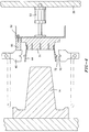
- FIG. 6 shows an insert 44 lodged in its position in the space 76 defined by the mold core and cavity prior to injection of the plastic material.
- FIG. 6 also shows the manner in which the mold splits 45 are accommodated by shaped mold cavity and mold core portions 80, 82.
- Plastic material is injected into the space 76 via nozzle 78. The plastic material flows around the insert 44 and incorporates same into the molded article being formed.
- the mold portions 11 and 12 are moved to their open position. During this opening operation, the molded article remains on the core 14.
- the carrier plate 20 is moved from the outboard position to a position intermediate the mold halfs where one of the sets of receiving stations is aligned with each mold core(s) 14.
- FIG. 7 illustrates an alternative embodiment wherein an insert 57 of elongated conical or tubular construction is to be loaded.
- the insert is not held on a mandrel. Instead, it is held in a receptacle 58 which is mounted to the structural channel 52.
- the insert 57 may be held in place in receptacle 58 by applying vacuum or other alternate means of retention.
- the receptacle 58 on the channel 52 moves the insert 57 to a point where mold splits 45 grasp the insert 57 and remove it from the receptacle 58.
- the mold splits 45 then carry the insert 57 the remainder of the distance until it is seated on the core 14.
- FIG. 8 shows the insert 58 lodged in its position in the cavity while the mold is closed.
- the operation of the apparatus 10 after molding has been completed is as follows. Once the mold is opened, the carrier plate 20 moves into place between the mold halves 11 and 12 with the receiving stations 21, 22 opposite the mold cores 14.
- the mold splits holding plate 46 commonly referred to as a slide, then moves forward with the mold splits 45 toward the receiving stations and once the molded article has partially entered the receiving station, the mold splits 45 continue to move forward but also move apart from each other until the molded article is no longer in contact with the mold splits and is fully engaged in a respective receiving station.
- the carrier plate 20 then indexes laterally a short distance, enough to move the molded article in the receiving station aside from being in axial alignment with the mold core 14 and to position the insert 44, 57 to be loaded in direct axial alignment with a respective mold core 14.
- the insert holding means 51, 58 is then extended, with the insert 44, 57 toward and over the core 14 until the insert is positioned a predetermined distance past the plane of the forward face of the opened mold splits. At that point, the insert holding means 51, 52, and 53 contact the mold splits by way of bumper pad forward face 56 hitting the front surface of mold split 45 and together they are pushed by actuating cylinder 53 to return the mold splits 45 to the rearward position.
- the mold splits come slowly together gripping or enveloping all or part of the insert and are thereby interactively removing or receiving the insert from the carrier plate insert loading means.
- the insert holding means 51, 52 and 53 are then retracted and the carrier plate 20 is removed to a location outside the mold for insert loading onto the carrier plate and molded part unloading, as required.
- the mold is closed and plastic injection is initiated.
- the apparatus of the present invention has numerous advantages associated with it. For example, a single device, namely the carrier plate described herein, loads the mold with inserts and unloads the completed article from the mold. Still further, the carrier plate performs the loading and unloading operations from a single face. Still further, the apparatus mechanically grips, holds or envelopes an insert in the cavity space. Still further, the apparatus lends itself to a method of installing an insert into a mold where the mold is dynamically interactive with the insertion means of the carrier plate.
Abstract
Description
- The present invention relates to an improved apparatus and method for removing molded articles from a multi-cavity injection mold and loading inserts into the cavity of the same mold. The apparatus and the method of the present invention have particular utility in the manufacture of laminated plastic containers suitable for holding foods, beverages and chemicals.
- The art of molding through, around or adjacent inserts placed in an injection molding cavity are well known in the injection molding industry. A number of different methods have been developed to load the inserts to be included within the molded article and to unload the molded article from the machine. Typically, the method that is used for a particular molding system takes into account the size, shape and number of the inserts to be loaded and such other factors as cost, degree of automation, complexity, speed and reliability.
- For example, U.S. Patent No. 3,837,772 to Van de Walker et al. illustrates a top entry robot system which is fed with inserts which are held in place on the robot using a vacuum. Upon opening the mold, a transfer plate moves into position opposite core pins in the mold. When the transfer plate is in this position, the vacuum is substituted by a pressure which forces the inserts onto the core pins where they are held in place by a vacuum applied to the core pins. If the inserts are open-ended, this vacuum method may not be feasible or effective.
- U.S. Patent No. 4,648,825 to Heil et al. illustrates a different system having a horizontal gantry structure which spans perpendicularly across the injection machine. An arm which depends from one end of the gantry secures a load carrier while another arm depending from the opposite end of the gantry secures an unload carrier. The arms move toward each other when the mold is opened to perform the loading and unloading functions. This approach disadvantageously requires two tooling arms, occupies substantial floor space on both sides of the machine, and is very costly.
- European patent document No. 0 357 777 to Orimoto et al. shows a plastic mouth insert which is loaded into the injection mold. The purpose of this insert is to provide heat resistance in the neck finish area which is required during subsequent operations in making a container. As discussed in this patent document, it is advantageous to accurately center the insert in the cavity and to support it in place as the injected plastic flows around it. For the purpose of loading the insert into the injection mold, it is recommended to position the insert in place between the mold splits, then close the splits in the conventional manner. In some cases, it may not be feasible or practical to deliver the insert from the carrier plate to its final position in the mold due to space restrictions or alignment problems and a co-operative effort from both carrier plate and mold are essential. Where molds already employ the use of moving mold ejection components, the return stroke of the components can provide the double function of insert retrieval, saving redundant motion and time. Hence, the loading device should also be capable of working in concert with the most advanced molds as previously discussed, which incorporate non-rectilinear mold splits motion.
- Accordingly, it is a principal object of the present invention to provide an improved molding apparatus which uses a single compact carrier plate for the loading of mold inserts and the unloading of molded articles.
- It is a further object of the present invention to provide an improved molding apparatus as above which mechanically interacts with a carrier plate insert loading device to effectively aid in the reception and lodgment of an insert in the mold cavity space prior to injection.
- It is still a further object of the present invention to provide an improved molding apparatus as above which actively grips and holds or contains an insert in the cavity space.
- It is yet a further object of the present invention to provide an improved process for molding an article wherein inserts can be more readily inserted into the mold cavity and molded articles can be unloaded.
- Still further objects and advantages to the present invention will become more apparent from the following description and drawings wherein like reference elements depict like elements.
- The foregoing objects and advantages may be readily obtained by the improved molding apparatus and process of the present invention. In accordance with the present invention, the improved molding apparatus includes a first mold half having one or more core portions and a second mold half having one or more cavity portions. The first and second mold halfs are movable between an open position and a closed position wherein said core and cavity portions define at least one space in the shape of the article to be molded. The molding apparatus further includes a carrier plate for receiving the molded article(s) after the molding cycle has been completed and for holding the insert(s) to be incorporated into the molded article. The carrier plate is movable from a first position between the mold halfs when the mold halfs are in an open position to a second position outside of the mold halfs. The carrier plate is also indexable between a first position where receptacle(s) for receiving the molded article(s) are aligned with the mold core portion(s) and a second position wherein means for holding the insert(s) is aligned with the mold core portion(s).
- The method of the present invention broadly comprises the steps of providing a first mold half having a mold core portion and a second mold half having a mold cavity portion; placing at least one insert on said mold core portion while said mold halfs are in an open position by aligning a carrier plate with means for holding said at least one insert with said mold core portion and transferring said at least one insert to said mold core portion; withdrawing said carrier plate from between said mold halfs; moving said mold halfs so that said mold core portion abuts said mold cavity portion; injecting plastic material into a space defined by said abutted mold core and mold cavity portions to form at least one molded article having at least one insert therein, moving said mold halfs to a mold open position, and moving said carrier plate into said position between said mold halfs to remove the at least one molded article.
-
- FIG. 1 illustrates a top view of an apparatus for producing plastic articles;
- FIG. 2 is an end view of a mold cavity plate and a carrier plate when viewed in the direction "A" shown in FIG. 1 with the carrier plate being in an outboard position;
- FIG. 3 is a top view of a carrier plate in a position to load inserts onto mold core portions of the apparatus of FIG. 1 with the insert holding means shown in partial cross section;
- FIG. 4 is a top view showing an insert in an extended position between two mold splits;
- FIG. 5 is a top view showing an insert being gripped by the mold splits;
- FIG. 6 is a sectional view showing an insert in a mold closed position;
- FIG. 7 illustrates an alternative embodiment of an insert to be incorporated into a molded article and an alternative device for holding said insert; and
- FIG. 8 illustrates the insert of FIG. 7 in a mold closed position.
- Referring now to the drawings, FIG. 1 illustrates an apparatus for producing plastic articles in accordance with the present invention. The apparatus includes a
molding machine 10 preferably comprising a multicavity machine. The number of cavities and the arrangement thereof shown in FIG. 1 are exemplificative only. It should be recognized that any convenient number of cavities and any suitable arrangement of the cavities may be employed in themachine 10. In fact, one could use a single cavity arrangement, although multicavity arrangements are preferred for economic reasons. - The
machine 10 includes afirst mold half 11 which is a cavity half and asecond mold half 12 which is a core half. Thefirst mold half 11 has at least onecavity 13 therein and preferably a plurality ofcavities 13. A representative cavity arrangement is shown in FIG. 2. This arrangement has two spaced rows ofcavities 13 with each row containing eight cavities. Thesecond mold half 12 has at least oneelongate core 14 therein with the number of cores corresponding to the number of cavities. Core(s) 14 are each engageable with a respective cavity for seating therein in a mold-closed position to form a closed mold for the formation of one or more plastic articles therein by injection molding. The number of articles formed in an injection molding cycle will depend on the number of cavities and corresponding cores. Normally, the core(s) 14 reciprocate from a mold-closed position seated in said cavities for the formation of the molded articles to a mold-open position spaced from said cavities forming a gap between the cores and cavities for ejection of the molded articles. FIG. 1 shows the first and second mold portions in a mold open position. Themold portions tie rods 15 and may be powered by any convenient motive means known in the art, such as byhydraulic cylinder 16, in a predetermined cycle. Molten plastic material is injected into aspace 76 formed between each core and cavity in the mold-closed position by known injection molding procedures. - It is preferred to retain the formed articles on
cores 14 after formation of the articles and upon reciprocation of the mold portions from the mold-closed position to the mold-open position. Acarrier plate 20 is provided to receive the molded articles removed from thecores 14. Removal of the articles from the cores onto thecarrier plate 20 may be accomplished by blowing air throughvent lines 17 and/or by the use of astripper plate 18 reciprocating onguide pins 19. - The
carrier plate 20 is movable from the outboard position shown in FIGS. 1 and 2 to a position between themold halfs carrier plate 20. One such mechanism is shown in U.S. Reissue Patent No. 33,237 to Delfer which is hereby incorporated by reference herein. -
Carrier plate 20 is provided with at least one set ofreceivers 21 for cooling the molded plastic articles. If a longer cooling time in the receiver is desired or needed, multiple sets of receivers, such asreceivers carrier plate receivers 21 and a second set ofcarrier plate receivers 22. Thecarrier plate 20 also includes a set ofinsert holders 23, which are positionally arranged in like manner toreceivers sets mold portion cavities 13, with each of said sets being spaced apart by a fixed distance. - FIG. 3 shows a top view of a
carrier plate 20 having two columns or sets 23 ofinserts 44 in alignment withmold cores 14 having a complementary configuration. Mold splits 45 mounted to themold core half 12 are shown in a forward extended position. The mold splits 45 are fastened toslides 46 which move the mold splits 45, and a molded article held by the mold splits, axially off arespective core 14. The article is released from the grasp of the mold splits through separation of same occurring at a point X, toward the end of the ejection stroke. Cams or other mechanical devices well known in the art may be employed to dictate the exact distance the mold splits will separate from each other and the position at which they will separate. - The
carrier plate 20 has one ormore mandrels 51 mounted thereto to hold insert(s) 44. Eachmandrel 51 can be made of a flexible material such as a plastic with a hollow core and serrated sides which act as fingers to spring against and hold the inside diameter of theinsert 44. Eachmandrel 51 is preferably mounted on astructural channel 52 which is fastened to and positioned by actuating piston-cylinder unit 53. The piston-cylinder unit 53 is used to extend thechannel 52 and themandrel 51 and thereby advance theinsert 44 to an axial position between the open mold splits 45. Of course, there are numerous methods for holding an insert on an insert holder dependent on its size and shape and how it must interact with the cooperating mold components which are to receive the insert. This is but one example. - Adjacent the columns of
insert holders 51 are the columns of receivingstations Bumper pads 55 are fastened to thestructural channel 52 and are sized such that theirforward face 56 is a prescribed distance from the base of theinsert 44. As shown in FIG. 4, when themandrel holding channel 52 moves forward, theface 56 of thebumper pad 55 hits a corresponding plane on the mold split 45. Thebumper pad 55 thereby defines the correct axial position of the insert between the mold splits. As theactuating cylinder 53 continues to push forward, the relative axial position of both theinsert 44 and the mold splits 45 are kept constant. As the mold splits 45 move inward toward the center axis of arespective core 14, the mold splits 45 come together to grip or envelope theinsert 44. To this end, each mold split 45 has anotch 70 for gripping or receiving aportion 72 of theinsert 44. - FIG. 5 shows the moment when the
insert 44 is first closed upon by the mold splits 45. Further movement of the mold splits to their seated position effectively strips the insert from themandrel 51. After the insert has been stripped from themandrel 51, thecarrier plate 20 is moved from a position where the insert(s) are aligned with the mold core(s) 14 toward the outboard position and themold halfs - FIG. 6 shows an
insert 44 lodged in its position in thespace 76 defined by the mold core and cavity prior to injection of the plastic material. FIG. 6 also shows the manner in which the mold splits 45 are accommodated by shaped mold cavity andmold core portions 80, 82. Plastic material is injected into thespace 76 vianozzle 78. The plastic material flows around theinsert 44 and incorporates same into the molded article being formed. After the plastic material has been cooled and solidified, themold portions core 14. After the molds have reached the open position, thecarrier plate 20 is moved from the outboard position to a position intermediate the mold halfs where one of the sets of receiving stations is aligned with each mold core(s) 14. Theslides 46 are then moved toward thecarrier plate 20 and the molded article is unloaded into one of the receivingstations carrier plate 20. The operation ofcarrier plate 20 in this respect is the same as in the aforementioned U.S. Reissue Patent No. 33,237 which is again hereby incorporated by reference herein. - FIG. 7 illustrates an alternative embodiment wherein an
insert 57 of elongated conical or tubular construction is to be loaded. The insert is not held on a mandrel. Instead, it is held in areceptacle 58 which is mounted to thestructural channel 52. Theinsert 57 may be held in place inreceptacle 58 by applying vacuum or other alternate means of retention. As described above, thereceptacle 58 on thechannel 52 moves theinsert 57 to a point where mold splits 45 grasp theinsert 57 and remove it from thereceptacle 58. The mold splits 45 then carry theinsert 57 the remainder of the distance until it is seated on thecore 14. FIG. 8 shows theinsert 58 lodged in its position in the cavity while the mold is closed. - The operation of the
apparatus 10 after molding has been completed is as follows. Once the mold is opened, thecarrier plate 20 moves into place between the mold halves 11 and 12 with the receivingstations mold cores 14. The mold splits holdingplate 46, commonly referred to as a slide, then moves forward with the mold splits 45 toward the receiving stations and once the molded article has partially entered the receiving station, the mold splits 45 continue to move forward but also move apart from each other until the molded article is no longer in contact with the mold splits and is fully engaged in a respective receiving station. Thecarrier plate 20 then indexes laterally a short distance, enough to move the molded article in the receiving station aside from being in axial alignment with themold core 14 and to position theinsert respective mold core 14. The insert holding means 51, 58 is then extended, with theinsert cylinder 53 to return the mold splits 45 to the rearward position. As the rearward mold splits motion takes place, the mold splits come slowly together gripping or enveloping all or part of the insert and are thereby interactively removing or receiving the insert from the carrier plate insert loading means. The insert holding means 51, 52 and 53 are then retracted and thecarrier plate 20 is removed to a location outside the mold for insert loading onto the carrier plate and molded part unloading, as required. With the insert now supported in place by the mold splits, the mold is closed and plastic injection is initiated. - The apparatus of the present invention has numerous advantages associated with it. For example, a single device, namely the carrier plate described herein, loads the mold with inserts and unloads the completed article from the mold. Still further, the carrier plate performs the loading and unloading operations from a single face. Still further, the apparatus mechanically grips, holds or envelopes an insert in the cavity space. Still further, the apparatus lends itself to a method of installing an insert into a mold where the mold is dynamically interactive with the insertion means of the carrier plate.
Claims (13)
- A machine for molding a plastic article which includes an insert, said machine comprising a first mold half (12) having a core portion (14) and a second mold half (11) having a cavity portion (13), said first and second mold halfs being movable between an open position and a closed position wherein said core and cavity portions define a space in the shape of the article to be molded, wherein said improvement comprises:
a carrier plate (20) having means (21, 22) for receiving a molded article and means (51, 52, 58) for carrying an insert (44, 57) to be incorporated into said molded article;
said carrier plate being movable between an outboard position and a first position wherein said insert is aligned with said mold core portion; and
said carrier plate further being movable to a second position wherein said means for receiving said molded article is aligned with said mold core portion. - A machine according to claim 1 further being characterized by means (53) for moving said insert carrying means towards the mold core portion and into an extended position.
- A machine according to claim 2 wherein said insert carrying means comprises a holder (51, 58) for said insert and a support member (52) mounted to said holder and said moving means comprises a piston-cylinder unit mounted to said carrier plate and connected to said support member.
- A machine according to claim 3 wherein said holder (51) comprises a mandrel having means for engaging inner surfaces of said insert (44) and said inner surface engaging means comprises serrated sides on said mandrel.
- A machine according to claim 3 wherein said holder (58) comprises a receptacle having a central bore in which said insert (57) resides and further comprises vacuum means for retaining said insert in said bore in said receptacle.
- A machine according to claim 2 further characterized by:
means (45) for gripping said insert and for removing said insert from said insert carrying means when said insert carrying means is moved from an extended position to a retracted position. - A machine according to claim 6 wherein said gripping means comprises two axially movable mold splits and each said mold split has a notch (70) for receiving a portion (72) of said insert.
- A machine according to claim 7 wherein said mold core portion and said mold cavity portion are shaped to accommodate said mold splits when said mold cavity portion and mold core portion are in an abutting relationship.
- A machine according to claim 7 further characterized by means (55) for identifying the correct axial position of said insert between said mold splits, said identifying means comprising a bumper associated with said mold splits.
- A machine according to claim 1 wherein:
said mold core half has a plurality of mold cores on a first face;
said mold cavity half has a plurality of mold cavities on a first face thereof;
said plurality of mold cores being equal in number to said plurality of mold cavities and being aligned with said plurality of mold cavities; and
said carrier plate has a plurality of insert carrying means for carrying a plurality of inserts equal in number to the plurality of mold cores and a plurality of molded article receiving means at least equal in number to the plurality of mold cores. - A method for manufacturing a molded article having an insert therein, said method being characterized by the steps of:
providing a first mold half (12) having a mold core portion (14) and a second mold half (11) having a mold cavity portion (13);
placing an insert (44, 57) on said mold core portion by aligning a carrier plate (20) with means (51, 58) for holding said insert with said mold core portion and transferring said insert to a position surrounding said mold core portion;
withdrawing said carrier plate from between said first and second mold halfs;
moving said first and second halfs to a molding position wherein said mold core portion and said mold cavity portion define a space in the shape of the article to be molded; and
forming said molded article with said insert by injecting molten plastic material into said space. - A method according to claim 11 further being characterized by:
moving said first and second mold halfs to a mold open position;
moving said carrier plate between said mold halfs and positioning said carrier plate so as to receive said molded article; and
indexing said carrier plate after said molded article has been received so that said mold core portion is aligned with a new insert carried by said carrier plate. - A method according to claim 11 wherein said transferring step comprises moving said holding means toward said mold core portion and into an extended position and gripping said insert after said holding means has reached said extended position.
Applications Claiming Priority (2)
| Application Number | Priority Date | Filing Date | Title |
|---|---|---|---|
| US229007 | 1988-08-05 | ||
| US08/229,007 US5527173A (en) | 1994-04-18 | 1994-04-18 | Apparatus for producing plastic articles with inserts |
Publications (3)
| Publication Number | Publication Date |
|---|---|
| EP0678366A2 true EP0678366A2 (en) | 1995-10-25 |
| EP0678366A3 EP0678366A3 (en) | 1995-11-29 |
| EP0678366B1 EP0678366B1 (en) | 1998-07-15 |
Family
ID=22859458
Family Applications (1)
| Application Number | Title | Priority Date | Filing Date |
|---|---|---|---|
| EP95104593A Expired - Lifetime EP0678366B1 (en) | 1994-04-18 | 1995-03-29 | Apparatus and method for producing plastic articles |
Country Status (6)
| Country | Link |
|---|---|
| US (2) | US5527173A (en) |
| EP (1) | EP0678366B1 (en) |
| JP (1) | JP3124904B2 (en) |
| AT (1) | ATE168315T1 (en) |
| DE (1) | DE69503421T2 (en) |
| ES (1) | ES2120648T3 (en) |
Cited By (1)
| Publication number | Priority date | Publication date | Assignee | Title |
|---|---|---|---|---|
| WO2001060579A1 (en) * | 2000-02-15 | 2001-08-23 | Sas Automation Ltd. | Molding apparatus and method using a robot to introduce an insert into a mold |
Families Citing this family (31)
| Publication number | Priority date | Publication date | Assignee | Title |
|---|---|---|---|---|
| CA2165871C (en) * | 1994-12-30 | 2002-03-26 | Tadayoshi Takashima | Parison forming apparatus and parison forming method |
| FI97610C (en) * | 1995-09-26 | 1997-01-27 | Fibox Oy Ab | Plant for molding of plastic products |
| US5645865A (en) * | 1995-12-22 | 1997-07-08 | Husky Injection Molding Systems Ltd. | Insert molding system |
| US5971618A (en) | 1996-05-26 | 1999-10-26 | Valu Engineering, Inc. | Flange bearing having reinforced molded housing |
| NL1003366C2 (en) * | 1996-06-18 | 1997-12-19 | Fico Bv | Apparatus and method for encapsulating products. |
| JP3357942B2 (en) * | 1997-07-16 | 2002-12-16 | 株式会社前田製作所 | Method for producing spouted lid and mold structure therefor |
| US6101791A (en) * | 1998-04-03 | 2000-08-15 | Louviere; Kent A. | Method of making a plurality of interconnected vials |
| DE19817657A1 (en) * | 1998-04-21 | 1999-10-28 | Stihl Maschf Andreas | Spark plug connector for engine of hand-guided working machine |
| US6106748A (en) * | 1998-06-10 | 2000-08-22 | Carter Wallace, Inc. | Method for removing prophylactic devices from mandrels |
| US6517757B1 (en) | 1999-12-03 | 2003-02-11 | The Plastic Moldings Corporation | Methods for molding a part around an insert |
| US6464922B1 (en) | 1999-12-10 | 2002-10-15 | Autotec, Inc. | Insertion device for plastic molding |
| US6764634B2 (en) * | 2000-08-03 | 2004-07-20 | Michelin Recherche Et Technique S.A. | Method for molding a support |
| US20030032675A1 (en) * | 2001-02-15 | 2003-02-13 | Franz G. Andrew | Manufacture of thyroid hormone tablets having consistent active moiety amounts |
| US6572745B2 (en) | 2001-03-23 | 2003-06-03 | Virotek, L.L.C. | Electrochemical sensor and method thereof |
| US20040084809A1 (en) * | 2002-11-05 | 2004-05-06 | Vanderploeg James A. | Side shuttle apparatus and method for an injection molding machine |
| DE10331519A1 (en) * | 2003-07-11 | 2005-02-03 | Hekuma Gmbh | Handling system for an injection molding machine and method for introducing an application into the injection mold |
| MXPA06003734A (en) | 2003-10-03 | 2007-03-26 | Grupo Convermex S A De C V | Method and apparatus for producing labeled, plastic foam containers, and product of same. |
| DE10355018B4 (en) * | 2003-11-25 | 2011-06-22 | MHT Mold & Hotrunner Technology AG, 65239 | Cavity structure |
| US7128564B2 (en) * | 2003-12-11 | 2006-10-31 | Husky Injection Molding Systems Ltd. | Simplified in-mold article handling system and a method for handling molded articles |
| FR2874350B1 (en) * | 2004-08-18 | 2007-12-21 | Faurecia Interieur Ind Snc | MOLD FOR INJECTION MOLDING OF A PLASTIC PIECE AND MOLDING METHOD |
| JP3786946B1 (en) * | 2005-01-24 | 2006-06-21 | 株式会社三井ハイテック | Permanent magnet resin sealing method |
| US20060269652A1 (en) * | 2005-05-24 | 2006-11-30 | Husky Injection Molding Systems Ltd. | Article moving apparatus configured for molding machine |
| US7364423B2 (en) * | 2005-05-24 | 2008-04-29 | Husky Injection Molding Systems Ltd. | Article moving apparatus configured for a molding machine |
| US20060279023A1 (en) * | 2005-06-08 | 2006-12-14 | Walsh Thomas J | Precision loader of injection molds |
| KR101030482B1 (en) * | 2006-01-11 | 2011-04-25 | 가부시키가이샤 미츠이하이테크 | Method of resin sealing permanent magnets in laminated rotor core |
| US8349240B2 (en) | 2011-03-25 | 2013-01-08 | Honda Motor Co., Ltd. | Hidden parting line mold and hidden parting line molding technique using associated part removal device |
| CN107775884B (en) * | 2016-08-24 | 2024-03-26 | 浙江豪声电子科技股份有限公司 | Injection mold and processing technology thereof |
| GB2566752B (en) * | 2017-09-26 | 2020-09-16 | Univ Cranfield | Method of manufacturing a moulded article |
| DE102019126939B4 (en) * | 2019-10-08 | 2022-02-10 | Lisa Dräxlmaier GmbH | MOLD HALF AND METHOD FOR MAKING AN INJECTION MOLDING PART WITH AT LEAST ONE BOLT-LIKE INSERT |
| KR102370936B1 (en) * | 2020-08-26 | 2022-03-08 | 주식회사 서연이화 | Apparatus and method of forming insert mold |
| US20220379527A1 (en) * | 2021-05-27 | 2022-12-01 | Spidermind Games Limited | Embedding objects in castings |
Citations (5)
| Publication number | Priority date | Publication date | Assignee | Title |
|---|---|---|---|---|
| JPS59178162A (en) * | 1983-03-29 | 1984-10-09 | Ube Ind Ltd | Method and device for feeding insert and extracting product in molding machine |
| JPS59227429A (en) * | 1983-06-09 | 1984-12-20 | Hitachi Ltd | Automatic apparatus of injection molding work |
| JPS62134233A (en) * | 1985-12-06 | 1987-06-17 | Toyoda Gosei Co Ltd | Molding machine with conveyance device |
| FR2606702A1 (en) * | 1986-11-19 | 1988-05-20 | Dromigny Pierre | OBJECT MOLDING MACHINE COMPRISING A COATING FILM TRANSPORT DEVICE AND A DEVICE FOR EVACUATING THE MOLDED OBJECT |
| JPH0334811A (en) * | 1989-06-30 | 1991-02-14 | Pentel Kk | Robot device for simultaneously performing insert and takeout |
Family Cites Families (22)
| Publication number | Priority date | Publication date | Assignee | Title |
|---|---|---|---|---|
| US4289817A (en) * | 1970-09-14 | 1981-09-15 | Valyi Emery I | Decorated multilayered hollow plastic container |
| US3837772A (en) * | 1970-10-08 | 1974-09-24 | California Injection Molding C | Apparatus for molding articles containing inserts and means for feeding inserts to the mold |
| US4013748A (en) * | 1971-12-30 | 1977-03-22 | Valyi Emery I | Method for making composite plastic article |
| CH614645A5 (en) * | 1976-06-09 | 1979-12-14 | Buehler Ag Geb | |
| EP0101095B1 (en) * | 1982-08-17 | 1988-11-17 | Dai Nippon Insatsu Kabushiki Kaisha | Method and device for injection molding articles while simultaneously forming patterns thereon |
| US4797244A (en) * | 1982-09-29 | 1989-01-10 | American National Can Company | Multiwalled container and method of making same |
| DE3486012T2 (en) * | 1983-05-25 | 1993-04-15 | Showa Denko Kk | INJECTION MOLDING METHOD FOR THE PRODUCTION OF CONTAINER LIDS. |
| US4838776A (en) * | 1983-08-18 | 1989-06-13 | Hasl Siegfried C | Label transferring apparatus for blow molding machines |
| US4571320A (en) * | 1984-10-31 | 1986-02-18 | General Motors Corporation | Method and apparatus for loading and unloading sheet molding compound in and from a press |
| US4942008A (en) * | 1985-07-10 | 1990-07-17 | Cahill John W | Process for molding a multiple layer structure |
| JPS6270010A (en) * | 1985-09-24 | 1987-03-31 | Matsushita Electric Works Ltd | Lead frame feeding-unloading device in encapsulation of electronic parts |
| US4679997A (en) * | 1985-11-25 | 1987-07-14 | Owens-Illinois, Inc. | Apparatus for delivering labels to blow molds of a plastic container blowing machine and removing the blown containers with the labels thereon |
| US4648825A (en) * | 1986-03-14 | 1987-03-10 | General Electric Company | Plastic molding apparatus |
| US4732726A (en) * | 1986-09-18 | 1988-03-22 | E. W. Mold & Tool Co., Inc. | Injection mold with insert transfer means and method |
| US4721452A (en) * | 1987-03-23 | 1988-01-26 | Husky Injection Molding Systems Ltd. | Apparatus for producing hollow plastic articles |
| USRE33237E (en) * | 1987-03-23 | 1990-06-19 | Husky Injection Molding Systems Ltd. | Apparatus for producing hollow plastic articles |
| JPS6426420A (en) * | 1987-07-23 | 1989-01-27 | Nissha Printing | Device for injection molding and simultaneous decorating and manufacture of injection-molded and simultaneously decorated product |
| JPH0757500B2 (en) * | 1987-10-31 | 1995-06-21 | 日精エー・エス・ビー機械株式会社 | How to insert a piece into a preform mouth mold |
| JPH0230782A (en) * | 1988-04-05 | 1990-02-01 | Fuji Photo Film Co Ltd | Method for recovering silver from photographic processing solution |
| US5297897A (en) * | 1989-11-24 | 1994-03-29 | Asm Fico Tooling B.V. | Single-strip molding apparatus |
| JPH0741648B2 (en) * | 1990-12-28 | 1995-05-10 | 日プラ株式会社 | In-mold labeling container with thread bottom and manufacturing method thereof |
| JP3136685B2 (en) * | 1991-09-10 | 2001-02-19 | 住友化学工業株式会社 | Molding method of multilayer molded product |
-
1994
- 1994-04-18 US US08/229,007 patent/US5527173A/en not_active Expired - Lifetime
-
1995
- 1995-03-29 ES ES95104593T patent/ES2120648T3/en not_active Expired - Lifetime
- 1995-03-29 DE DE69503421T patent/DE69503421T2/en not_active Expired - Lifetime
- 1995-03-29 AT AT95104593T patent/ATE168315T1/en not_active IP Right Cessation
- 1995-03-29 EP EP95104593A patent/EP0678366B1/en not_active Expired - Lifetime
- 1995-04-12 JP JP07085828A patent/JP3124904B2/en not_active Expired - Fee Related
- 1995-10-26 US US08/548,454 patent/US5788905A/en not_active Expired - Lifetime
Patent Citations (5)
| Publication number | Priority date | Publication date | Assignee | Title |
|---|---|---|---|---|
| JPS59178162A (en) * | 1983-03-29 | 1984-10-09 | Ube Ind Ltd | Method and device for feeding insert and extracting product in molding machine |
| JPS59227429A (en) * | 1983-06-09 | 1984-12-20 | Hitachi Ltd | Automatic apparatus of injection molding work |
| JPS62134233A (en) * | 1985-12-06 | 1987-06-17 | Toyoda Gosei Co Ltd | Molding machine with conveyance device |
| FR2606702A1 (en) * | 1986-11-19 | 1988-05-20 | Dromigny Pierre | OBJECT MOLDING MACHINE COMPRISING A COATING FILM TRANSPORT DEVICE AND A DEVICE FOR EVACUATING THE MOLDED OBJECT |
| JPH0334811A (en) * | 1989-06-30 | 1991-02-14 | Pentel Kk | Robot device for simultaneously performing insert and takeout |
Non-Patent Citations (4)
| Title |
|---|
| PATENT ABSTRACTS OF JAPAN vol. 009 no. 034 (M-357) ,14 February 1985 & JP-A-59 178162 (UBE KOSAN KK) 9 October 1984, * |
| PATENT ABSTRACTS OF JAPAN vol. 009 no. 103 (M-377) ,8 May 1985 & JP-A-59 227429 (HITACHI SEISAKUSHO KK) 20 December 1984, * |
| PATENT ABSTRACTS OF JAPAN vol. 011 no. 356 (M-644) ,20 November 1987 & JP-A-62 134233 (TOYODA GOSEI CO LTD) 17 June 1987, * |
| PATENT ABSTRACTS OF JAPAN vol. 015 no. 168 (M-1107) ,26 April 1991 & JP-A-03 034811 (PENTEL KK) 14 February 1991, * |
Cited By (1)
| Publication number | Priority date | Publication date | Assignee | Title |
|---|---|---|---|---|
| WO2001060579A1 (en) * | 2000-02-15 | 2001-08-23 | Sas Automation Ltd. | Molding apparatus and method using a robot to introduce an insert into a mold |
Also Published As
| Publication number | Publication date |
|---|---|
| US5527173A (en) | 1996-06-18 |
| DE69503421T2 (en) | 1998-11-19 |
| DE69503421D1 (en) | 1998-08-20 |
| ES2120648T3 (en) | 1998-11-01 |
| EP0678366B1 (en) | 1998-07-15 |
| EP0678366A3 (en) | 1995-11-29 |
| US5788905A (en) | 1998-08-04 |
| JP3124904B2 (en) | 2001-01-15 |
| JPH0839608A (en) | 1996-02-13 |
| ATE168315T1 (en) | 1998-08-15 |
Similar Documents
| Publication | Publication Date | Title |
|---|---|---|
| US5788905A (en) | Method for producing molded articles having inserts incorporated therein | |
| US4609228A (en) | Method and machine for manufacturing brushes | |
| US4721452A (en) | Apparatus for producing hollow plastic articles | |
| USRE33237E (en) | Apparatus for producing hollow plastic articles | |
| US5447426A (en) | Take-off plate device | |
| AU735086B2 (en) | Method and device for making a container provided with a label | |
| US4983348A (en) | In-mold labeling of injection blow molded products | |
| US5744088A (en) | Method and apparatus for manufcturing hollow objects, in particular plastic preforms | |
| US6095788A (en) | Injection molding machine for manufacturing hollow plastic articles | |
| EP0183942B1 (en) | Stack-mold for injection blowing molding | |
| RU95120163A (en) | METHOD AND DEVICE FOR MANUFACTURE OF HOLLOW ITEMS, IN PARTICULAR PLASTIC Billets | |
| GB2293344A (en) | Cooling injection and blow moulded parisons | |
| US4769205A (en) | In-mold labeling method | |
| US4838776A (en) | Label transferring apparatus for blow molding machines | |
| EP0589383A1 (en) | Stripping station | |
| EP0339761A2 (en) | Apparatus for applying labels to blow molded articles | |
| US6454988B1 (en) | Indexing labeling magazine | |
| US3303256A (en) | Method of orienting and feeding traveler inserts to molding machines | |
| US4207134A (en) | Apparatus for the preparation of hollow plastic articles | |
| US4234302A (en) | Apparatus for the preparation of hollow plastic articles | |
| US4230298A (en) | Apparatus for the preparation of hollow plastic articles | |
| US4225304A (en) | Apparatus for the preparation of hollow plastic articles | |
| US4176151A (en) | Method for manufacturing an article stopper device | |
| CA1129613A (en) | Apparatus for the preparation of hollow plastic articles | |
| CA2233065A1 (en) | Method and apparatus for removing hollow plastic articles from an injection moulding machine |
Legal Events
| Date | Code | Title | Description |
|---|---|---|---|
| PUAI | Public reference made under article 153(3) epc to a published international application that has entered the european phase |
Free format text: ORIGINAL CODE: 0009012 |
|
| PUAL | Search report despatched |
Free format text: ORIGINAL CODE: 0009013 |
|
| AK | Designated contracting states |
Kind code of ref document: A2 Designated state(s): AT CH DE DK ES FR GB IT LI NL SE |
|
| AK | Designated contracting states |
Kind code of ref document: A3 Designated state(s): AT CH DE DK ES FR GB IT LI NL SE |
|
| RIN1 | Information on inventor provided before grant (corrected) |
Inventor name: MCGINLEY, THOMAS M. Inventor name: MILLER, WILLIAM E. C/O JOHNSON CONTROLS INC. |
|
| 17P | Request for examination filed |
Effective date: 19960209 |
|
| 17Q | First examination report despatched |
Effective date: 19960521 |
|
| GRAG | Despatch of communication of intention to grant |
Free format text: ORIGINAL CODE: EPIDOS AGRA |
|
| GRAG | Despatch of communication of intention to grant |
Free format text: ORIGINAL CODE: EPIDOS AGRA |
|
| GRAH | Despatch of communication of intention to grant a patent |
Free format text: ORIGINAL CODE: EPIDOS IGRA |
|
| GRAH | Despatch of communication of intention to grant a patent |
Free format text: ORIGINAL CODE: EPIDOS IGRA |
|
| GRAA | (expected) grant |
Free format text: ORIGINAL CODE: 0009210 |
|
| AK | Designated contracting states |
Kind code of ref document: B1 Designated state(s): AT CH DE DK ES FR GB IT LI NL SE |
|
| REF | Corresponds to: |
Ref document number: 168315 Country of ref document: AT Date of ref document: 19980815 Kind code of ref document: T |
|
| REG | Reference to a national code |
Ref country code: CH Ref legal event code: NV Representative=s name: FREI PATENTANWALTSBUERO Ref country code: CH Ref legal event code: EP |
|
| ITF | It: translation for a ep patent filed |
Owner name: OBEROSLER LUDWIG |
|
| REF | Corresponds to: |
Ref document number: 69503421 Country of ref document: DE Date of ref document: 19980820 |
|
| ET | Fr: translation filed | ||
| PG25 | Lapsed in a contracting state [announced via postgrant information from national office to epo] |
Ref country code: DK Free format text: LAPSE BECAUSE OF FAILURE TO SUBMIT A TRANSLATION OF THE DESCRIPTION OR TO PAY THE FEE WITHIN THE PRESCRIBED TIME-LIMIT Effective date: 19981015 |
|
| REG | Reference to a national code |
Ref country code: ES Ref legal event code: FG2A Ref document number: 2120648 Country of ref document: ES Kind code of ref document: T3 |
|
| PLBE | No opposition filed within time limit |
Free format text: ORIGINAL CODE: 0009261 |
|
| STAA | Information on the status of an ep patent application or granted ep patent |
Free format text: STATUS: NO OPPOSITION FILED WITHIN TIME LIMIT |
|
| 26N | No opposition filed | ||
| REG | Reference to a national code |
Ref country code: GB Ref legal event code: IF02 |
|
| REG | Reference to a national code |
Ref country code: CH Ref legal event code: NV Representative=s name: BOVARD AG PATENTANWAELTE |
|
| PGFP | Annual fee paid to national office [announced via postgrant information from national office to epo] |
Ref country code: FR Payment date: 20071130 Year of fee payment: 14 |
|
| PGFP | Annual fee paid to national office [announced via postgrant information from national office to epo] |
Ref country code: SE Payment date: 20080114 Year of fee payment: 14 Ref country code: NL Payment date: 20080111 Year of fee payment: 14 Ref country code: GB Payment date: 20080114 Year of fee payment: 14 |
|
| EUG | Se: european patent has lapsed | ||
| GBPC | Gb: european patent ceased through non-payment of renewal fee |
Effective date: 20090329 |
|
| NLV4 | Nl: lapsed or anulled due to non-payment of the annual fee |
Effective date: 20091001 |
|
| REG | Reference to a national code |
Ref country code: FR Ref legal event code: ST Effective date: 20091130 |
|
| PG25 | Lapsed in a contracting state [announced via postgrant information from national office to epo] |
Ref country code: NL Free format text: LAPSE BECAUSE OF NON-PAYMENT OF DUE FEES Effective date: 20091001 |
|
| PG25 | Lapsed in a contracting state [announced via postgrant information from national office to epo] |
Ref country code: GB Free format text: LAPSE BECAUSE OF NON-PAYMENT OF DUE FEES Effective date: 20090329 Ref country code: FR Free format text: LAPSE BECAUSE OF NON-PAYMENT OF DUE FEES Effective date: 20091123 |
|
| PGFP | Annual fee paid to national office [announced via postgrant information from national office to epo] |
Ref country code: ES Payment date: 20100215 Year of fee payment: 16 Ref country code: CH Payment date: 20100215 Year of fee payment: 16 |
|
| PGFP | Annual fee paid to national office [announced via postgrant information from national office to epo] |
Ref country code: IT Payment date: 20100303 Year of fee payment: 16 |
|
| PGFP | Annual fee paid to national office [announced via postgrant information from national office to epo] |
Ref country code: AT Payment date: 20100112 Year of fee payment: 16 |
|
| PGFP | Annual fee paid to national office [announced via postgrant information from national office to epo] |
Ref country code: DE Payment date: 20100215 Year of fee payment: 16 |
|
| REG | Reference to a national code |
Ref country code: CH Ref legal event code: PFA Owner name: HUSKY INJECTION MOLDING SYSTEMS LTD. Free format text: HUSKY INJECTION MOLDING SYSTEMS LTD.#500 QUEEN STREET SOUTH#BOLTON ONTARIO L7E 5S5 (CA) -TRANSFER TO- HUSKY INJECTION MOLDING SYSTEMS LTD.#500 QUEEN STREET SOUTH#BOLTON ONTARIO L7E 5S5 (CA) |
|
| PG25 | Lapsed in a contracting state [announced via postgrant information from national office to epo] |
Ref country code: SE Free format text: LAPSE BECAUSE OF NON-PAYMENT OF DUE FEES Effective date: 20090330 |
|
| REG | Reference to a national code |
Ref country code: CH Ref legal event code: PL |
|
| PG25 | Lapsed in a contracting state [announced via postgrant information from national office to epo] |
Ref country code: AT Free format text: LAPSE BECAUSE OF NON-PAYMENT OF DUE FEES Effective date: 20110329 |
|
| PG25 | Lapsed in a contracting state [announced via postgrant information from national office to epo] |
Ref country code: DE Free format text: LAPSE BECAUSE OF NON-PAYMENT OF DUE FEES Effective date: 20111001 Ref country code: CH Free format text: LAPSE BECAUSE OF NON-PAYMENT OF DUE FEES Effective date: 20110331 Ref country code: LI Free format text: LAPSE BECAUSE OF NON-PAYMENT OF DUE FEES Effective date: 20110331 |
|
| REG | Reference to a national code |
Ref country code: DE Ref legal event code: R119 Ref document number: 69503421 Country of ref document: DE Effective date: 20111001 |
|
| PG25 | Lapsed in a contracting state [announced via postgrant information from national office to epo] |
Ref country code: IT Free format text: LAPSE BECAUSE OF NON-PAYMENT OF DUE FEES Effective date: 20110329 |
|
| REG | Reference to a national code |
Ref country code: ES Ref legal event code: FD2A Effective date: 20120424 |
|
| PG25 | Lapsed in a contracting state [announced via postgrant information from national office to epo] |
Ref country code: ES Free format text: LAPSE BECAUSE OF NON-PAYMENT OF DUE FEES Effective date: 20110330 |