EP0678314B1 - Fixation de ski - Google Patents
Fixation de ski Download PDFInfo
- Publication number
- EP0678314B1 EP0678314B1 EP95102865A EP95102865A EP0678314B1 EP 0678314 B1 EP0678314 B1 EP 0678314B1 EP 95102865 A EP95102865 A EP 95102865A EP 95102865 A EP95102865 A EP 95102865A EP 0678314 B1 EP0678314 B1 EP 0678314B1
- Authority
- EP
- European Patent Office
- Prior art keywords
- slide
- base plate
- ski
- binding element
- boot
- Prior art date
- Legal status (The legal status is an assumption and is not a legal conclusion. Google has not performed a legal analysis and makes no representation as to the accuracy of the status listed.)
- Expired - Lifetime
Links
- 239000000463 material Substances 0.000 abstract description 4
- 238000010276 construction Methods 0.000 description 10
- 238000013016 damping Methods 0.000 description 7
- 238000005096 rolling process Methods 0.000 description 5
- 230000035939 shock Effects 0.000 description 4
- 230000005540 biological transmission Effects 0.000 description 3
- 239000000523 sample Substances 0.000 description 3
- 230000006835 compression Effects 0.000 description 2
- 238000007906 compression Methods 0.000 description 2
- 238000001914 filtration Methods 0.000 description 2
- 239000000725 suspension Substances 0.000 description 2
- 229910000831 Steel Inorganic materials 0.000 description 1
- 239000006096 absorbing agent Substances 0.000 description 1
- 238000004519 manufacturing process Methods 0.000 description 1
- 238000000034 method Methods 0.000 description 1
- 238000003825 pressing Methods 0.000 description 1
- 230000000717 retained effect Effects 0.000 description 1
- 239000011435 rock Substances 0.000 description 1
- 230000035807 sensation Effects 0.000 description 1
- 239000010959 steel Substances 0.000 description 1
Images

Classifications
-
- A—HUMAN NECESSITIES
- A63—SPORTS; GAMES; AMUSEMENTS
- A63C—SKATES; SKIS; ROLLER SKATES; DESIGN OR LAYOUT OF COURTS, RINKS OR THE LIKE
- A63C5/00—Skis or snowboards
- A63C5/06—Skis or snowboards with special devices thereon, e.g. steering devices
- A63C5/07—Skis or snowboards with special devices thereon, e.g. steering devices comprising means for adjusting stiffness
-
- A—HUMAN NECESSITIES
- A63—SPORTS; GAMES; AMUSEMENTS
- A63C—SKATES; SKIS; ROLLER SKATES; DESIGN OR LAYOUT OF COURTS, RINKS OR THE LIKE
- A63C9/00—Ski bindings
- A63C9/001—Anti-friction devices
Definitions
- the invention relates to a fastening element intended to retain the end of a shoe in support on a sliding board, especially on a ski. More specifically, the invention relates to an element of binding intended to retain the rear end of a shoe.
- the invention also relates to a binding assembly intended to retain a boot on a ski. comprising such a fixing element.
- rear fasteners are known. They are most often associated with a front fixing element. They usually include a shoe retaining jaw carried by a body. The body is movable along a base or slide in the longitudinal direction ski, and a spring, commonly called recoil spring, resists the movement of the body back, leaning on a stop.
- This stopper usually a latch or screw cooperating with the slide, defines the nominal position of the body. This nominal position is changed to adapt the fastening element to the length of the shoe, or to modify the restoring force that the recoil spring exerts on the body in the presence of the shoe.
- the rear fastener also includes a support plate for receiving the rear end of the shoe sole.
- This support plate is usually associated or well to the body, or else to the slide.
- Patent application WO91 / 08807 proposes a construction according to lacquered only the support plate of the shoe is mobile and cushioned by a deformable block. This construction gives good results. Indeed, the connection between the support plate and the shoe allows selective damping of stresses. The vertical stresses are damped, while the rolling stresses pass without damping between the ski and the shoe.
- the invention aims to further improve the connection between the boot and the ski.
- Another object of the invention is also to optimize the compromise between the amortization of the shoe and the precision of the ski driving.
- Another aim is to propose a construction which is simple to carry out.
- the rotational mobility of the slide around a transverse axis means that the fastening element as a whole rocks during vertical movements. There is amortization according to a vertical direction. In addition, the inertia of the moving elements is increased. Solicitations from roll however pass without damping between the slide and the ski, because of the articulation cross that connects them.
- an anti-roll means is added between the slide and the ski. This means improves the quality of the transmission of the roll stresses which pass between the shoe and skiing.
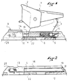
- Figure 1 is a side view, in partial section of a fastening element according to a first embodiment for implementing the invention.
- Figure 2 is a side sectional view of the base plate and the slide fitted to the element Figure 1.
- Figure 3 is a partial exploded perspective view of the front part.
- Figure 4 illustrates an alternative embodiment of the link.
- Figure 1 shows by way of illustration of the invention a fastening element 1 comprising known manner a shoe retaining jaw 2 carried by a body 3.
- the body is mounted sliding along a slide 4 oriented in the longitudinal direction defined by the ski.
- a way such as a latch 5 clamped in the slide defines a nominal position, and the body can move back towards the bolt against the restoring force opposed to it by the recoil spring 6.
- the slide shown in the figures has in section a shape of "C" lying and open to the top.
- the body is guided in the slide by skids which circulate in the folded edges of the slide. This is not limiting and any other method of assembling the body on the slide suitable, in particular any other suitable section of slide.
- the fixing element 1 also has a support plate 9 which is intended to receive the support of the shoe.
- the support plate 9 has downwards and backwards a end piece 10 which is fitted into the profile of the slide.
- this tip is located under the platform of the plate 9 so that it can be engaged on the slide from the rear, and be slid along the slide to its service position in Figure 1.
- the slide is wrapped in a base plate 11.
- the base plate 11 is intended to be assembled to the ski by any suitable means, for example by screws. It has a bottom 12 intended to be pressed against the ski. The background may show large openings. Laterally, the base plate has two wings 13 and 14 which go up along lateral edges of the slide 4. These wings close above the slide 4 by flanges 15, 16, which leave a sufficient distance between them so that the body can pass.
- the bottom 12 and the edges 15 and 16 are slightly convergent towards the rear so that in a vertical direction, there is no play between the rear part of the slide 4 and the plate based. There is, however, a clearance on the front of the slide.
- the rear part of the slide has a horizontal tab 18.
- This tab is possibly divided into two segments.
- the tab 18 is housed in a recess 19 of dimension base plate, so as to prevent backward movement of the slide 4 relative to the base plate. Relative forward movement is possible, however.
- the front part therefore has mobility relative to the ski, which is oriented in a direction approximately vertical.
- the rear part of the slide cannot oscillate for a rolling movement, because it is kept without play between the bottom and the edges of the base plate.
- any other suitable means is suitable for ensuring this connection, in particular a transverse pin connecting the rear parts of the slide and the base plate.
- a block of elastically deformable material shown diagrammatically at 22 This block possibly has damping properties. He could be replaced or assisted by any suitable deformable means, in particular a spring, a shock absorber, or the like.
- the block 22 has a thickness provided to keep the front of the slide at rest in its high position, or close to this position.
- the block 22 also allows, by its elasticity, to make up for the operating clearances due to the manufacturing tolerances of the parts. Its stiffness is designed so that it compresses under the action of the skier's weight and the vertical stresses passing through at this level between the boot and the ski.
- the fastening element 1 can be associated with any suitable ski brake.
- the brake can have as a bearing the front of the base plate 11. It can also have an independent bearing relative to the front of the baseplate and attached to the ski with it.
- the fastener works as follows.
- the back of the boot is connected to the ski by through the block 22 which compresses with the lowering of the support plate 9 relatively skiing.
- shocks and jolts from the ski are transmitted to the shoe in a vertical direction via block 22 which performs filtering or cushioning according to its hardness.
- the back of the shoe is somehow mounted on a suspension which operates according to a vertical direction.
- the connection between the slide and the base plate also prevents a movement relative to the roll of these two elements.
- the fastening element 1 has a additional anti-roll means located towards the front of the slide.
- the anti-roll means comprises a large rod 25 connected to the base plate 11 and to the slide 4 by an articulation around an axis horizontal and transverse.
- the link 25 has a width close to the width of the slide 4.
- the link can be made from a flat profile whose two side ends are folded back to form the sides.
- its torsional rigidity can be reinforced by a fold transverse 26 forming a rib.
- any other suitable construction of the link agrees.
- the link could be made from a steel wire folded into a wide "U”.
- the link 25 is pierced with orifice which define two housings 28 and 29 for axes articulation 30 and 31.
- the axes 30 and 31 are mutually parallel and are arranged substantially in a horizontal plane.
- the ends of the axis 30 are carried by the base plate 11, more precisely by its wings 13 and 14.
- the axis 31 is located behind the axis 30. According to the figures, the slide has two fronts legs 34 and 35 folded so that their ends come to rest on the axis 31. Legs 34 and 35 are widely separated from each other.
- the support plate 9 which is slidably mounted along the slide is engaged on the front until it comes into abutment against the legs 34 and 35. In this position, the ribs 37, that it has on its underside, protrude between the legs. These ribs have an orifice transverse 38 located in the extension of the interior of the fold which have the tabs 34 and 35, which is crossed by the axis 31. A connection is thus produced by pressing the slide on the axis 31, with locking by the cooperation between the axis and the support plate 9. Naturally any other connection appropriate is suitable.
- the link 25 has only one degree of freedom in rotation about the axis 30 relative to the plate base, and around the axis 31 relative to the slide.
- the link prevents the front of the slide from rolling. However, the link offers no resistance to vertical movements from the front of the slide, these movements cause compression of block 22.
- the support plate 9 lowers, causing the link and slide to rotate, as well as forward movement of the slide. This movement creates additional compression of the recoil spring.
- one of the housings of the link in this case the housing 29 'is oblong.
- the oblong is oriented in a horizontal plane, to prevent movement of axis 30 roll.
- one of the other orifices crossed by the axes 30 and 31 could be oblong.
- the device according to the invention which has been described can be adapted to other constructions, and in particular those described in French patent applications published under the numbers 2 680 697, 2 684 885, 2 687,325, on behalf of the plaintiff.
Landscapes
- Footwear And Its Accessory, Manufacturing Method And Apparatuses (AREA)
- Transition And Organic Metals Composition Catalysts For Addition Polymerization (AREA)
- Magnetic Heads (AREA)
- Die Bonding (AREA)
- Sheet Holders (AREA)
Description
Claims (3)
- Elément de fixation (1) destiné à retenir l'extrémité d'une chaussure en appui contre un ski, comprenant un corps (3) porté par une embase formant glissière (4), comprenant une plaque de support (9) destinée à supporter l'extrémité de la semelle de chaussure, la glissière (4) étant montée de façon mobile par rapport à une plaque de base (11) destinée à être solidarisée au ski, étant reliée à la plaque de base par une articulation autour d'un axe horizontal et transversal situé vers une extrémité de la plaque de base dite extrémité arrière, un moyen de rappel élastique (22) étant situé sous la glissière vers son autre extrémité dite extrémité avant, de façon à s'opposer élastiquement à un basculement de la glissière vers la plaque de base une biellette (25) reliant l'extrémité avant de la glissière à la plaque de base, ladite biellette (25) étant articulée autour de deux axes parallèles (30, 31), horizontaux et transversaux, l'un porté par la plaque de base (11) et l'autre porté par la glissière (4) pour réaliser une liaison anti-roulis entre l'extrémité avant de la glissière et la plaque de base.
- Elément selon la revendication 1, caractérisé par le fait que l'un (29') des paliers des axes de la biellette (25') présente une forme oblongue orientée dans un plan horizontal.
- Ensemble d'éléments de retenue d'une chaussure sur un ski, caractérisé par le fait qu'il comprend un élément de fixation selon l'une quelconque des revendications précédentes, cet élément de fixation constituant un élément de fixation arrière et étant associé à un élément de fixation avant et un organe de raidissement qui s'étend entre l'élément de fixation avant et l'extrémité avant de la glissière (4).
Applications Claiming Priority (2)
| Application Number | Priority Date | Filing Date | Title |
|---|---|---|---|
| FR9403615 | 1994-03-24 | ||
| FR9403615A FR2718047B1 (fr) | 1994-03-29 | 1994-03-29 | Elément de fixation destiné à retenir l'extrémité d'une chaussure sur une planche de glisse. |
Publications (2)
| Publication Number | Publication Date |
|---|---|
| EP0678314A1 EP0678314A1 (fr) | 1995-10-25 |
| EP0678314B1 true EP0678314B1 (fr) | 1998-09-30 |
Family
ID=9461493
Family Applications (1)
| Application Number | Title | Priority Date | Filing Date |
|---|---|---|---|
| EP95102865A Expired - Lifetime EP0678314B1 (fr) | 1994-03-24 | 1995-03-01 | Fixation de ski |
Country Status (5)
| Country | Link |
|---|---|
| EP (1) | EP0678314B1 (fr) |
| JP (1) | JPH07265485A (fr) |
| AT (1) | ATE171633T1 (fr) |
| DE (1) | DE69505037T2 (fr) |
| FR (1) | FR2718047B1 (fr) |
Families Citing this family (2)
| Publication number | Priority date | Publication date | Assignee | Title |
|---|---|---|---|---|
| FR2796851B3 (fr) * | 1999-07-27 | 2001-09-28 | Salomon Sa | Dispositif d'interface entre une chaussure et un ski |
| FR2974515B1 (fr) * | 2011-04-27 | 2013-04-26 | Rossignol Sa | Talonniere de fixation de securite pour ski alpin |
Family Cites Families (6)
| Publication number | Priority date | Publication date | Assignee | Title |
|---|---|---|---|---|
| AT358446B (de) * | 1978-02-20 | 1980-09-10 | Tyrolia Freizeitgeraete | Sicherheitsskibindung |
| FR2640152B1 (fr) * | 1988-12-13 | 1991-03-29 | Salomon Sa | Fixation arriere de ski alpin |
| FR2654635A1 (en) * | 1989-11-22 | 1991-05-24 | Salomon Sa | Device for mounting a boot on a ski |
| FR2686798B1 (fr) * | 1992-01-31 | 1994-03-25 | Salomon Sa | Dispositif visant a modifier la repartition d'un ski sur sa surface de glisse et ski equipe d'un tel dispositif. |
| FR2687325B1 (fr) * | 1992-02-18 | 1995-10-27 | Salomon Sa | Dispositif visant a modifier la repartition naturelle d'un ski sur sa surface de glisse, et ski equipe d'un tel dispositif. |
| ATE132049T1 (de) * | 1992-04-17 | 1996-01-15 | Salomon Sa | Ski mit auflageplatte |
-
1994
- 1994-03-29 FR FR9403615A patent/FR2718047B1/fr not_active Expired - Fee Related
-
1995
- 1995-03-01 DE DE69505037T patent/DE69505037T2/de not_active Expired - Fee Related
- 1995-03-01 EP EP95102865A patent/EP0678314B1/fr not_active Expired - Lifetime
- 1995-03-01 AT AT95102865T patent/ATE171633T1/de not_active IP Right Cessation
- 1995-03-23 JP JP7063813A patent/JPH07265485A/ja not_active Withdrawn
Also Published As
| Publication number | Publication date |
|---|---|
| EP0678314A1 (fr) | 1995-10-25 |
| FR2718047B1 (fr) | 1996-05-31 |
| JPH07265485A (ja) | 1995-10-17 |
| ATE171633T1 (de) | 1998-10-15 |
| FR2718047A1 (fr) | 1995-10-06 |
| DE69505037T2 (de) | 1999-04-29 |
| DE69505037D1 (de) | 1998-11-05 |
Similar Documents
| Publication | Publication Date | Title |
|---|---|---|
| EP0556610B1 (fr) | Dispositif pour modifier la répartition naturelle d'un ski sur sa surface de glisse | |
| EP0624113B1 (fr) | Dispositif pour modifier la repartition d'un ski sur sa surface de glisse | |
| FR2704440A1 (fr) | Planche de glisse, notamment surf de neige. | |
| EP0626873B1 (fr) | Dispositif pour modifier la repartition naturelle d'un ski sur sa surface de glisse et frein de ski | |
| EP0880981A1 (fr) | Dispositif interface entre une chaussure et un ski alpin | |
| EP0617638B1 (fr) | Dispositif visant a repartir la pression d'un ski sur une surface de glisse | |
| EP0658360B1 (fr) | Dispositif interface entre un ski et des éléments de fixation | |
| EP0599041B1 (fr) | Dispositif d'interface entre un ski et des éléments de fixation | |
| FR2707514A1 (fr) | Elément de fixation de ski alpin. | |
| FR2718047A1 (fr) | Elément de fixation destiné à retenir l'extrémité d'une chaussure sur une planche de glisse. | |
| EP0505463B1 (fr) | Fixation de securite de ski alpin | |
| FR2655867A1 (fr) | Fixation de securite de ski alpin. | |
| EP0688586B1 (fr) | Elément de fixation, notamment élément de fixation de ski | |
| FR2800623A1 (fr) | Dispositif interface entre un ski et des elements de retenue d'une chaussure sur le ski et ski ainsi equipe | |
| EP0700699B1 (fr) | Fixation de ski | |
| FR2796852A1 (fr) | Dispositif interface entre une chaussure et un ski | |
| FR2699418A1 (fr) | Dispositif interface entre un ski et des éléments de fixation. | |
| FR2715862A1 (fr) | Elément de fixation de ski alpin équipé d'un dispositif de compensation. | |
| EP2781242B1 (fr) | Plaque d'interface pour ski | |
| EP0878217B1 (fr) | Plaque d'appui pour fixation de sécurité | |
| FR2810893A1 (fr) | Dispositif interface entre un ski alpin et des elements de retenue de la chaussure sur le ski | |
| EP1072294A1 (fr) | Dispositif interface entre une chaussure et un ski | |
| FR2741816A1 (fr) | Element de retenue de l'avant d'une chaussure sur une planche de glisse, notamment un ski | |
| FR2815264A1 (fr) | Dispositif interface entre une chaussure et des elements de retenue de la chaussure sur un ski alpin | |
| FR2796300A1 (fr) | Dispositif interface entre un ski et des elements de retenue de la chaussure sur le ski |
Legal Events
| Date | Code | Title | Description |
|---|---|---|---|
| PUAI | Public reference made under article 153(3) epc to a published international application that has entered the european phase |
Free format text: ORIGINAL CODE: 0009012 |
|
| AK | Designated contracting states |
Kind code of ref document: A1 Designated state(s): AT CH DE IT LI |
|
| 17P | Request for examination filed |
Effective date: 19960109 |
|
| 17Q | First examination report despatched |
Effective date: 19960913 |
|
| GRAG | Despatch of communication of intention to grant |
Free format text: ORIGINAL CODE: EPIDOS AGRA |
|
| GRAG | Despatch of communication of intention to grant |
Free format text: ORIGINAL CODE: EPIDOS AGRA |
|
| GRAH | Despatch of communication of intention to grant a patent |
Free format text: ORIGINAL CODE: EPIDOS IGRA |
|
| GRAH | Despatch of communication of intention to grant a patent |
Free format text: ORIGINAL CODE: EPIDOS IGRA |
|
| GRAA | (expected) grant |
Free format text: ORIGINAL CODE: 0009210 |
|
| AK | Designated contracting states |
Kind code of ref document: B1 Designated state(s): AT CH DE IT LI |
|
| PG25 | Lapsed in a contracting state [announced via postgrant information from national office to epo] |
Ref country code: IT Free format text: LAPSE BECAUSE OF FAILURE TO SUBMIT A TRANSLATION OF THE DESCRIPTION OR TO PAY THE FEE WITHIN THE PRE;WARNING: LAPSES OF ITALIAN PATENTS WITH EFFECTIVE DATE BEFORE 2007 MAY HAVE OCCURRED AT ANY TIME BEFORE 2007. THE CORRECT EFFECTIVE DATE MAY BE DIFFERENT FROM THE ONE RECORDED.SCRIBED TIME-LIMIT Effective date: 19980930 |
|
| REF | Corresponds to: |
Ref document number: 171633 Country of ref document: AT Date of ref document: 19981015 Kind code of ref document: T |
|
| REG | Reference to a national code |
Ref country code: CH Ref legal event code: EP |
|
| REF | Corresponds to: |
Ref document number: 69505037 Country of ref document: DE Date of ref document: 19981105 |
|
| PGFP | Annual fee paid to national office [announced via postgrant information from national office to epo] |
Ref country code: AT Payment date: 19990305 Year of fee payment: 5 |
|
| PG25 | Lapsed in a contracting state [announced via postgrant information from national office to epo] |
Ref country code: LI Free format text: LAPSE BECAUSE OF NON-PAYMENT OF DUE FEES Effective date: 19990331 Ref country code: CH Free format text: LAPSE BECAUSE OF NON-PAYMENT OF DUE FEES Effective date: 19990331 |
|
| PGFP | Annual fee paid to national office [announced via postgrant information from national office to epo] |
Ref country code: DE Payment date: 19990426 Year of fee payment: 5 |
|
| PLBE | No opposition filed within time limit |
Free format text: ORIGINAL CODE: 0009261 |
|
| STAA | Information on the status of an ep patent application or granted ep patent |
Free format text: STATUS: NO OPPOSITION FILED WITHIN TIME LIMIT |
|
| 26N | No opposition filed | ||
| REG | Reference to a national code |
Ref country code: CH Ref legal event code: PL |
|
| PG25 | Lapsed in a contracting state [announced via postgrant information from national office to epo] |
Ref country code: AT Free format text: LAPSE BECAUSE OF NON-PAYMENT OF DUE FEES Effective date: 20000301 |
|
| PG25 | Lapsed in a contracting state [announced via postgrant information from national office to epo] |
Ref country code: DE Free format text: LAPSE BECAUSE OF NON-PAYMENT OF DUE FEES Effective date: 20010103 |