EP0677430A1 - An automobile bumper - Google Patents
An automobile bumper Download PDFInfo
- Publication number
- EP0677430A1 EP0677430A1 EP95102171A EP95102171A EP0677430A1 EP 0677430 A1 EP0677430 A1 EP 0677430A1 EP 95102171 A EP95102171 A EP 95102171A EP 95102171 A EP95102171 A EP 95102171A EP 0677430 A1 EP0677430 A1 EP 0677430A1
- Authority
- EP
- European Patent Office
- Prior art keywords
- bracket
- shell
- opening
- vehicle body
- bumper according
- Prior art date
- Legal status (The legal status is an assumption and is not a legal conclusion. Google has not performed a legal analysis and makes no representation as to the accuracy of the status listed.)
- Granted
Links
- 239000000463 material Substances 0.000 claims abstract description 9
- 230000000295 complement effect Effects 0.000 claims abstract description 3
- 238000009877 rendering Methods 0.000 claims 2
- 239000006260 foam Substances 0.000 description 7
- 230000010355 oscillation Effects 0.000 description 3
- 230000003534 oscillatory effect Effects 0.000 description 2
- 239000004033 plastic Substances 0.000 description 2
- 230000035939 shock Effects 0.000 description 2
- 239000004743 Polypropylene Substances 0.000 description 1
- -1 polypropylene Polymers 0.000 description 1
- 229920001155 polypropylene Polymers 0.000 description 1
- QQONPFPTGQHPMA-UHFFFAOYSA-N propylene Natural products CC=C QQONPFPTGQHPMA-UHFFFAOYSA-N 0.000 description 1
- 125000004805 propylene group Chemical group [H]C([H])([H])C([H])([*:1])C([H])([H])[*:2] 0.000 description 1
Images
Classifications
-
- B—PERFORMING OPERATIONS; TRANSPORTING
- B60—VEHICLES IN GENERAL
- B60R—VEHICLES, VEHICLE FITTINGS, OR VEHICLE PARTS, NOT OTHERWISE PROVIDED FOR
- B60R19/00—Wheel guards; Radiator guards, e.g. grilles; Obstruction removers; Fittings damping bouncing force in collisions
- B60R19/02—Bumpers, i.e. impact receiving or absorbing members for protecting vehicles or fending off blows from other vehicles or objects
- B60R19/18—Bumpers, i.e. impact receiving or absorbing members for protecting vehicles or fending off blows from other vehicles or objects characterised by the cross-section; Means within the bumper to absorb impact
- B60R19/22—Bumpers, i.e. impact receiving or absorbing members for protecting vehicles or fending off blows from other vehicles or objects characterised by the cross-section; Means within the bumper to absorb impact containing mainly cellular material, e.g. solid foam
-
- B—PERFORMING OPERATIONS; TRANSPORTING
- B60—VEHICLES IN GENERAL
- B60R—VEHICLES, VEHICLE FITTINGS, OR VEHICLE PARTS, NOT OTHERWISE PROVIDED FOR
- B60R19/00—Wheel guards; Radiator guards, e.g. grilles; Obstruction removers; Fittings damping bouncing force in collisions
- B60R19/02—Bumpers, i.e. impact receiving or absorbing members for protecting vehicles or fending off blows from other vehicles or objects
- B60R19/24—Arrangements for mounting bumpers on vehicles
-
- B—PERFORMING OPERATIONS; TRANSPORTING
- B60—VEHICLES IN GENERAL
- B60R—VEHICLES, VEHICLE FITTINGS, OR VEHICLE PARTS, NOT OTHERWISE PROVIDED FOR
- B60R19/00—Wheel guards; Radiator guards, e.g. grilles; Obstruction removers; Fittings damping bouncing force in collisions
- B60R19/02—Bumpers, i.e. impact receiving or absorbing members for protecting vehicles or fending off blows from other vehicles or objects
- B60R19/18—Bumpers, i.e. impact receiving or absorbing members for protecting vehicles or fending off blows from other vehicles or objects characterised by the cross-section; Means within the bumper to absorb impact
- B60R2019/1886—Bumper fascias and fastening means therefor
-
- B—PERFORMING OPERATIONS; TRANSPORTING
- B60—VEHICLES IN GENERAL
- B60R—VEHICLES, VEHICLE FITTINGS, OR VEHICLE PARTS, NOT OTHERWISE PROVIDED FOR
- B60R19/00—Wheel guards; Radiator guards, e.g. grilles; Obstruction removers; Fittings damping bouncing force in collisions
- B60R19/02—Bumpers, i.e. impact receiving or absorbing members for protecting vehicles or fending off blows from other vehicles or objects
- B60R19/24—Arrangements for mounting bumpers on vehicles
- B60R2019/245—Arrangements for mounting bumpers on vehicles with adjusting means to compensate manufacturing tolerances, e.g. between bumper and energy absorbers
Definitions
- the present invention refers to an automobile bumper.
- bumpers made of a foam body rigidly fixed to the vehicle body.
- a rigid outer shell of semi-rigid plastic material is then rigidly secured to the foam body.
- the outer shell is an additional finishing member that is not meant to work as a bumper.
- the bumper function is demanded to the foam body and the corresponding cross member of the vehicle body.
- an automobile bumper of the type consisting of two complementary joining parts: a body of crash yieldable material fixed to the vehicle body; a shell of semi-rigid material substantially congruent with the external outline of said body and covering the outer part thereof; characterised in that the shell is secured to the vehicle body by means of a double hinge securing system, whereby said shell is capable of oscillating relative to the vehicle body and said body in a longitudinal vertical plane and in a transversal vertical plane.
- a bumper 10 essentially consists of the union of two pieces: a body 11 of foam or other material capable of yielding to absorb considerable crashes, and an outer protection shell 12 of semi-rigid plastic material, preferably polypropylene. Shell 12 is so shaped as to be substantially congruent with the external outline of body 11.
- Foam body 11 preferably of propylene, is mounted to the vehicle body. More particularly, body 11 is fixed to cross member 13 of the vehicle body by means of a number of fastening screws 14.
- each opening 15 is obtained in foam body 11.
- the inwardly facing portion of each opening 15 is fitted with a tubular distance tube 16 for contrasting head portions 14a.
- shell 12 is also connected directly to cross member 13 by a centring pin 18 for facilitating correct mounting of the shell.
- One or more longitudinal grooves 19 can be provided on the outer side of body 11, according to the design of outer shell 12. Grooves 19 are so shaped as to seat corresponding stiffening ribs 20 of the shell.
- shell 12 is at first connected to the top portion of cross member 13. Then, the sides are connected to the body-work, while the bottom is fitted with a double hinge securing system connecting the shell to the vehicle body enabling the latter to perform small oscillatory movements about two perpendicular axes (x and y).
- a first bracket 21 is integral with one of the stiffening ribs 20. Bracket 21 is obtained as a whole with said rib or successively fixed thereto.
- a slot 22 is provided on bracket 21 substantially parallel to longitudinal axis z (FIG. 3).
- a second bracket 23 is interposed between foam body 11 and cross member 13. Bracket 23 is has an upper bore 24 for accommodating one of the screws 14 so that once the shell is mounted, bracket 23 is between body 11 and cross member 13 while being capable of rotating to some extent in a vertical plane about fastening screw 14, as indicated by arrows A in FIG. 3.
- Bracket 23 consists of a rigid, elongated flat member twisted longitudinally 90 degrees so that its lower side 25 lies in a plane substantially parallel to that of slot 22 obtained in the first bracket.
- a vertical slot 26 is obtained in side 25 parallel to slot 22, whereby as the outer shell 12 is being mounted, the two facing slots 22, 26 determine a common opening point in which a bolt 27 is inserted and fastened.
- shell 12 can elastically absorb the shock by oscillating in a vertical longitudinal plane (yz) about the axis of bolt 27. Simultaneously, slight transverse oscillation is permitted about screw 14. These oscillations, in combination with the elongated shape of slots 22 and 26 allow to recover cut down clearances during assembling operations. Particularly, rotation of bracket 23 about screw 14 allows to regain clearances in the direction of axis x, horizontal slot 22 allows clearance regain in the horizontal direction of axis z, while slot 26 provides regain in the vertical direction of axis y. Obviously, this securing system provides for return of the shell 12 to its original position after the crash.
- the disclosed perpendicular slot fastening arrangement Besides absorbing elastically crashes while the vehicle is being used, the disclosed perpendicular slot fastening arrangement provides for cutting down clearance in the longitudinal and vertical directions during assembling. Oscillation of bracket 23 allows to recuperate clearance in the transversal direction.
- flexibility in the vertical longitudinal plane is achieved by means of a flexible bracket 30 obtained as a whole with the outer shell.
- the free end portion of flexible bracket 30 is provided with a vertical slot 31 oriented in the vertical longitudinal plane yz.
- flexible bracket 30 forms a horizontally folded portion 32 providing required flexibility in a longitudinal vertical plane.
- Connection to intermediate bracket 23 also in this case is attained by means of a bolt 27 which inserts in vertical slot 31 and a circular opening 33 of bracket 23. Flexibility of bracket 30 renders overlapping of the two slots easy.
- FIG. 5 depicts a further embodiment of the bumper according to the present invention. This example differs from the embodiment of FIG. 4 in that the bracket provides a further vertically folded portion 35 that renders the shell capable of oscillating elastically also in the horizontal plane xz.
Landscapes
- Engineering & Computer Science (AREA)
- Mechanical Engineering (AREA)
- Vibration Dampers (AREA)
- Optical Head (AREA)
- Connection Of Plates (AREA)
Abstract
Description
- The present invention refers to an automobile bumper.
- At present there are known bumpers made of a foam body rigidly fixed to the vehicle body. A rigid outer shell of semi-rigid plastic material is then rigidly secured to the foam body. The outer shell is an additional finishing member that is not meant to work as a bumper. The bumper function is demanded to the foam body and the corresponding cross member of the vehicle body.
- The above kind of arrangement, that replaces conventional bumpers made of a single piece, allows to have to replace only the outer half-shell in case of serious damage. However, as the bumper consists of more than one piece, a number of adjustments have to be carried out to assemble and mount the bumper for eliminating clearance between the various pieces.
- It is an object of this invention to provide a new system of binding the outer half-shell to the vehicle body, so as to recuperate clearances in any direction.
- It is another object of the present invention to provide a binding system of the half-shell capable of facilitating mounting operations and allowing to avoid particular adjustments and relevant loss of time.
- Another limit concerning prior art is represented by the fact that the half-shell, having to be rigidly secured to its supporting member, is not capable of absorbing shocks, even small entity ones.
- Accordingly, it is a further object of this invention to provide a system for binding the outer protection half-shell which allows the latter to accomplish small oscillatory movements in a vertical lengthwise plane and transverse vertical plane, absorbing small crashes and regaining its own original position.
- In accordance with one aspect of the invention as claimed, these objects are accomplished by the provision of an automobile bumper, of the type consisting of two complementary joining parts:
a body of crash yieldable material fixed to the vehicle body;
a shell of semi-rigid material substantially congruent with the external outline of said body and covering the outer part thereof;
characterised in that the shell is secured to the vehicle body by means of a double hinge securing system, whereby said shell is capable of oscillating relative to the vehicle body and said body in a longitudinal vertical plane and in a transversal vertical plane. - In order that the present invention may be well understood there will now be described a few preferred embodiments thereof, given by way of example, reference being made to the accompanying drawings, in which:
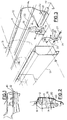
- FIG. 1
- is a perspective view of a bumper according to the present invention mounted to the rear of an automobile;
- FIG. 2
- is a partially sectioned view, to an enlarged scale, of the bumper taken along line A-A of FIG. 1;
- FIG. 3
- is an exploded perspective view of the bumper of FIG. 2;
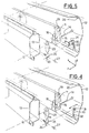
- FIG. 4
- is a view, similar to that of FIG. 3, depicting an alternative embodiment of the invention; and
- FIG. 5
- is a view, similar to those of FIGS. 3 and 4, depicting a further variant concerning mounting of the bumper of this invention.
- With reference initially to FIGS. 1 to 3, a
bumper 10 according to the present invention essentially consists of the union of two pieces: abody 11 of foam or other material capable of yielding to absorb considerable crashes, and anouter protection shell 12 of semi-rigid plastic material, preferably polypropylene.Shell 12 is so shaped as to be substantially congruent with the external outline ofbody 11. -
Foam body 11, preferably of propylene, is mounted to the vehicle body. More particularly,body 11 is fixed to crossmember 13 of the vehicle body by means of a number of fasteningscrews 14. - Special outwardly diverging
openings 15 of substantially frustoconical shape are obtained infoam body 11. The inwardly facing portion of eachopening 15 is fitted with atubular distance tube 16 for contrastinghead portions 14a. - Preferably, as shown in FIG. 2,
shell 12 is also connected directly tocross member 13 by acentring pin 18 for facilitating correct mounting of the shell. - One or more
longitudinal grooves 19 can be provided on the outer side ofbody 11, according to the design ofouter shell 12.Grooves 19 are so shaped as to seat correspondingstiffening ribs 20 of the shell. - As said,
shell 12 is at first connected to the top portion ofcross member 13. Then, the sides are connected to the body-work, while the bottom is fitted with a double hinge securing system connecting the shell to the vehicle body enabling the latter to perform small oscillatory movements about two perpendicular axes (x and y). - According to the present invention, a
first bracket 21 is integral with one of thestiffening ribs 20. Bracket 21 is obtained as a whole with said rib or successively fixed thereto. Aslot 22 is provided onbracket 21 substantially parallel to longitudinal axis z (FIG. 3). Asecond bracket 23 is interposed betweenfoam body 11 andcross member 13. Bracket 23 is has an upper bore 24 for accommodating one of thescrews 14 so that once the shell is mounted,bracket 23 is betweenbody 11 andcross member 13 while being capable of rotating to some extent in a vertical plane about fasteningscrew 14, as indicated by arrows A in FIG. 3.Bracket 23 consists of a rigid, elongated flat member twisted longitudinally 90 degrees so that itslower side 25 lies in a plane substantially parallel to that ofslot 22 obtained in the first bracket. Avertical slot 26 is obtained inside 25 parallel toslot 22, whereby as theouter shell 12 is being mounted, the two facingslots bolt 27 is inserted and fastened. - Owing to this particular hinging arrangement, in case of
crashes occurring shell 12 can elastically absorb the shock by oscillating in a vertical longitudinal plane (yz) about the axis ofbolt 27. Simultaneously, slight transverse oscillation is permitted aboutscrew 14. These oscillations, in combination with the elongated shape ofslots bracket 23 aboutscrew 14 allows to regain clearances in the direction of axis x,horizontal slot 22 allows clearance regain in the horizontal direction of axis z, whileslot 26 provides regain in the vertical direction of axis y. Obviously, this securing system provides for return of theshell 12 to its original position after the crash. - Besides absorbing elastically crashes while the vehicle is being used, the disclosed perpendicular slot fastening arrangement provides for cutting down clearance in the longitudinal and vertical directions during assembling. Oscillation of
bracket 23 allows to recuperate clearance in the transversal direction. - With reference to FIG. 4, according to a second preferred embodiment of the present invention, flexibility in the vertical longitudinal plane is achieved by means of a
flexible bracket 30 obtained as a whole with the outer shell. The free end portion offlexible bracket 30 is provided with avertical slot 31 oriented in the vertical longitudinal plane yz. Near the point of connection to theouter shell 12,flexible bracket 30 forms a horizontally foldedportion 32 providing required flexibility in a longitudinal vertical plane. Connection tointermediate bracket 23 also in this case is attained by means of abolt 27 which inserts invertical slot 31 and acircular opening 33 ofbracket 23. Flexibility ofbracket 30 renders overlapping of the two slots easy. - FIG. 5 depicts a further embodiment of the bumper according to the present invention. This example differs from the embodiment of FIG. 4 in that the bracket provides a further vertically folded portion 35 that renders the shell capable of oscillating elastically also in the horizontal plane xz.
Claims (10)
- An automobile bumper, of the type consisting of two complementary joining parts:
a body (11) of crash yieldable material fixed to the vehicle body (13);
a shell (12) of semi-rigid material substantially congruent with the external outline of said body (11) and covering the outer part thereof;
characterised in that the shell (12) is secured to the vehicle body (13) by means of a double hinge securing system, whereby said shell (12) is capable of oscillating relative to the vehicle body (13) and said body (11) in a longitudinal vertical plane (yz) and in a transversal vertical plane (xy). - A bumper according to claim 1, characterised in that said double hinge securing system comprises a first bracket (23) having a first end portion hinged (14) for rotation in a transversal vertical plane (xy) to the vehicle body (13); said first bracket (23) having a second end portion hinged (27) for rotation in a longitudinal vertical plane (yz) to a second bracket (21, 30) extending from said shell (12).
- A bumper according to claim 2, characterised in that said second bracket (21, 30) is obtained as a whole with said shell (12).
- A bumper according to claim 2, characterised in that said first bracket (23) consists of a rigid, elongated flat member twisted longitudinally 90 degrees.
- A bumper according to claim 2, characterised in that said second end portion of said first bracket (23) provides a vertical longitudinal wall (25) wherein a first opening (26, 33) is obtained; a second opening (22, 31) substantially parallel to said first opening (26, 33) being obtained in said second bracket (21, 30); upon overlapping, said first (26, 33) opening and said second (22, 31) opening determining a common opening adapted for accommodating a fastening member (27) for securing said first (23) bracket to said second bracket (21, 30).
- A bumper according to claim 5, characterised in that said first opening (26) is a vertical slot and that said second opening (22) is a horizontal slot.
- A bumper according to claim 5, characterised in that said first opening (33) is a circular bore and that said second opening (31) is a vertical slot; said second bracket (30) forming a portion (32) folded parallel to the transversal axis (x) for rendering its end portion having the slot (31) flexible in the longitudinal vertical plane (yz).
- A bumper according to claim 7, characterised in that said second bracket (32) forms another folded portion (35) parallel to the vertical axis (y) for rendering its end portion having the slot (31) flexible also in the horizontal plane (xz).
- A bumper according to claims 1 and 2, characterised in that the first bracket (23) is hinged to the vehicle body (13) through a member (14) adapted for fixing said body (11) to the vehicle body.
- A bumper according to claim 1, characterised in that the shell (12) is directly secured to the vehicle body (13) through a centring pin (18).
Applications Claiming Priority (2)
| Application Number | Priority Date | Filing Date | Title |
|---|---|---|---|
| ITTO940294A IT1273155B (en) | 1994-04-14 | 1994-04-14 | BUMPER FOR VEHICLES |
| ITTO940294 | 1994-04-14 |
Publications (2)
| Publication Number | Publication Date |
|---|---|
| EP0677430A1 true EP0677430A1 (en) | 1995-10-18 |
| EP0677430B1 EP0677430B1 (en) | 1997-06-18 |
Family
ID=11412463
Family Applications (1)
| Application Number | Title | Priority Date | Filing Date |
|---|---|---|---|
| EP95102171A Expired - Lifetime EP0677430B1 (en) | 1994-04-14 | 1995-02-16 | An automobile bumper |
Country Status (3)
| Country | Link |
|---|---|
| EP (1) | EP0677430B1 (en) |
| DE (1) | DE69500358T2 (en) |
| IT (1) | IT1273155B (en) |
Cited By (2)
| Publication number | Priority date | Publication date | Assignee | Title |
|---|---|---|---|---|
| EP0894988A3 (en) * | 1997-07-29 | 2000-11-29 | Basf Aktiengesellschaft | Method for joining a foam core with a shell |
| EP3408160A4 (en) * | 2016-01-26 | 2019-06-26 | Compagnie Plastic Omnium | ADJUSTABLE SUPPORT FOR INSTALLING A VEHICLE BUMPER |
Families Citing this family (1)
| Publication number | Priority date | Publication date | Assignee | Title |
|---|---|---|---|---|
| DE102005051473A1 (en) * | 2005-10-25 | 2007-05-03 | Decoma (Germany) Gmbh | Holding device for supporting attachment parts on surrounding components in motor vehicle, has first component supported at second component for attaching holding device |
Citations (4)
| Publication number | Priority date | Publication date | Assignee | Title |
|---|---|---|---|---|
| US3850466A (en) * | 1972-08-14 | 1974-11-26 | A Yepis | Vehicle bumper and frame mounting |
| JPS596154A (en) * | 1982-07-01 | 1984-01-13 | Nissan Motor Co Ltd | Attachment mechanism for automobile bumper |
| US4457547A (en) * | 1981-11-06 | 1984-07-03 | Toyota Jidosha Kogyo Kabushiki Kaisha | Bumper reinforcement structure for vehicles |
| US4762352A (en) * | 1985-11-29 | 1988-08-09 | Honda Giken Kogyo Kabushiki Kaisha | Synthetic resin bumper assembly |
-
1994
- 1994-04-14 IT ITTO940294A patent/IT1273155B/en active IP Right Grant
-
1995
- 1995-02-16 DE DE69500358T patent/DE69500358T2/en not_active Expired - Fee Related
- 1995-02-16 EP EP95102171A patent/EP0677430B1/en not_active Expired - Lifetime
Patent Citations (4)
| Publication number | Priority date | Publication date | Assignee | Title |
|---|---|---|---|---|
| US3850466A (en) * | 1972-08-14 | 1974-11-26 | A Yepis | Vehicle bumper and frame mounting |
| US4457547A (en) * | 1981-11-06 | 1984-07-03 | Toyota Jidosha Kogyo Kabushiki Kaisha | Bumper reinforcement structure for vehicles |
| JPS596154A (en) * | 1982-07-01 | 1984-01-13 | Nissan Motor Co Ltd | Attachment mechanism for automobile bumper |
| US4762352A (en) * | 1985-11-29 | 1988-08-09 | Honda Giken Kogyo Kabushiki Kaisha | Synthetic resin bumper assembly |
Non-Patent Citations (1)
| Title |
|---|
| PATENT ABSTRACTS OF JAPAN vol. 8, no. 90 (M - 292) 25 April 1984 (1984-04-25) * |
Cited By (3)
| Publication number | Priority date | Publication date | Assignee | Title |
|---|---|---|---|---|
| EP0894988A3 (en) * | 1997-07-29 | 2000-11-29 | Basf Aktiengesellschaft | Method for joining a foam core with a shell |
| EP3408160A4 (en) * | 2016-01-26 | 2019-06-26 | Compagnie Plastic Omnium | ADJUSTABLE SUPPORT FOR INSTALLING A VEHICLE BUMPER |
| US10710530B2 (en) | 2016-01-26 | 2020-07-14 | Compagnie Plastic Omnium | Adjustable bracket for installation of a vehicle bumper |
Also Published As
| Publication number | Publication date |
|---|---|
| IT1273155B (en) | 1997-07-07 |
| EP0677430B1 (en) | 1997-06-18 |
| ITTO940294A0 (en) | 1994-04-14 |
| DE69500358D1 (en) | 1997-07-24 |
| ITTO940294A1 (en) | 1995-10-14 |
| DE69500358T2 (en) | 1997-10-09 |
Similar Documents
| Publication | Publication Date | Title |
|---|---|---|
| KR102273991B1 (en) | Frunk module mounting structure of front car body | |
| US4563028A (en) | Reinforcement member for a vehicle bumper | |
| EP1813485A1 (en) | Front structure of an automotive vehicle | |
| JP2002274430A (en) | Body front structure | |
| EP0677430B1 (en) | An automobile bumper | |
| KR100589270B1 (en) | Knee Bolster Mounting Structure for Glove Box | |
| JP2001039242A (en) | Front body structure of vehicle | |
| EP0256174B1 (en) | Automobile bumper | |
| FR2873652A1 (en) | Front part assembly for motor vehicle, has flexible brackets, each with one end to fix bumper skin and another end connected to front part of vehicle body`s wing, and horizontal reinforcement to connect skin fixing ends of brackets together | |
| KR20120061072A (en) | Bumper back-beam for vehicle | |
| JP2005537183A (en) | Automotive body with roof column | |
| US20040169401A1 (en) | Structuring air duct | |
| JP3125531B2 (en) | Vehicle body front structure and assembly method thereof | |
| JP3744063B2 (en) | Car door structure | |
| JP3624552B2 (en) | Front bumper structure of automobile | |
| EP1481849B1 (en) | Foldable warning triangle | |
| JPS6082465A (en) | Bamper side fixing section structure | |
| JP4466317B2 (en) | Mounting structure of equipment to vehicle instrument panel | |
| JPH0332447Y2 (en) | ||
| KR100527959B1 (en) | Structured members of automobile bumper | |
| KR101301748B1 (en) | Front end module carrier | |
| KR0132856Y1 (en) | Integrated bumper | |
| JP7035823B2 (en) | Subframe structure | |
| KR100324693B1 (en) | Mounting structure of front bumper for automobile | |
| KR0115981Y1 (en) | Bumper stay |
Legal Events
| Date | Code | Title | Description |
|---|---|---|---|
| PUAI | Public reference made under article 153(3) epc to a published international application that has entered the european phase |
Free format text: ORIGINAL CODE: 0009012 |
|
| AK | Designated contracting states |
Kind code of ref document: A1 Designated state(s): DE ES FR GB SE |
|
| 17P | Request for examination filed |
Effective date: 19951110 |
|
| GRAG | Despatch of communication of intention to grant |
Free format text: ORIGINAL CODE: EPIDOS AGRA |
|
| GRAH | Despatch of communication of intention to grant a patent |
Free format text: ORIGINAL CODE: EPIDOS IGRA |
|
| 17Q | First examination report despatched |
Effective date: 19961118 |
|
| GRAH | Despatch of communication of intention to grant a patent |
Free format text: ORIGINAL CODE: EPIDOS IGRA |
|
| GRAA | (expected) grant |
Free format text: ORIGINAL CODE: 0009210 |
|
| AK | Designated contracting states |
Kind code of ref document: B1 Designated state(s): DE ES FR GB SE |
|
| PG25 | Lapsed in a contracting state [announced via postgrant information from national office to epo] |
Ref country code: ES Free format text: THE PATENT HAS BEEN ANNULLED BY A DECISION OF A NATIONAL AUTHORITY Effective date: 19970618 |
|
| REF | Corresponds to: |
Ref document number: 69500358 Country of ref document: DE Date of ref document: 19970724 |
|
| PG25 | Lapsed in a contracting state [announced via postgrant information from national office to epo] |
Ref country code: SE Effective date: 19970918 |
|
| ET | Fr: translation filed | ||
| PLBE | No opposition filed within time limit |
Free format text: ORIGINAL CODE: 0009261 |
|
| STAA | Information on the status of an ep patent application or granted ep patent |
Free format text: STATUS: NO OPPOSITION FILED WITHIN TIME LIMIT |
|
| 26N | No opposition filed | ||
| REG | Reference to a national code |
Ref country code: GB Ref legal event code: IF02 |
|
| PGFP | Annual fee paid to national office [announced via postgrant information from national office to epo] |
Ref country code: FR Payment date: 20050121 Year of fee payment: 11 |
|
| PGFP | Annual fee paid to national office [announced via postgrant information from national office to epo] |
Ref country code: GB Payment date: 20050215 Year of fee payment: 11 |
|
| PGFP | Annual fee paid to national office [announced via postgrant information from national office to epo] |
Ref country code: DE Payment date: 20050427 Year of fee payment: 11 |
|
| PG25 | Lapsed in a contracting state [announced via postgrant information from national office to epo] |
Ref country code: GB Free format text: LAPSE BECAUSE OF NON-PAYMENT OF DUE FEES Effective date: 20060216 |
|
| PG25 | Lapsed in a contracting state [announced via postgrant information from national office to epo] |
Ref country code: DE Free format text: LAPSE BECAUSE OF NON-PAYMENT OF DUE FEES Effective date: 20060901 |
|
| GBPC | Gb: european patent ceased through non-payment of renewal fee |
Effective date: 20060216 |
|
| REG | Reference to a national code |
Ref country code: FR Ref legal event code: ST Effective date: 20061031 |
|
| PG25 | Lapsed in a contracting state [announced via postgrant information from national office to epo] |
Ref country code: FR Free format text: LAPSE BECAUSE OF NON-PAYMENT OF DUE FEES Effective date: 20060228 |