EP0677416A1 - Bearing cap and pump mounting flange for power take-off unit - Google Patents
Bearing cap and pump mounting flange for power take-off unit Download PDFInfo
- Publication number
- EP0677416A1 EP0677416A1 EP95302353A EP95302353A EP0677416A1 EP 0677416 A1 EP0677416 A1 EP 0677416A1 EP 95302353 A EP95302353 A EP 95302353A EP 95302353 A EP95302353 A EP 95302353A EP 0677416 A1 EP0677416 A1 EP 0677416A1
- Authority
- EP
- European Patent Office
- Prior art keywords
- bearing cap
- apertures
- mounting flange
- power take
- unit
- Prior art date
- Legal status (The legal status is an assumption and is not a legal conclusion. Google has not performed a legal analysis and makes no representation as to the accuracy of the status listed.)
- Granted
Links
- 230000002093 peripheral effect Effects 0.000 description 11
- 230000005540 biological transmission Effects 0.000 description 5
- 238000012423 maintenance Methods 0.000 description 1
Images


Classifications
-
- F—MECHANICAL ENGINEERING; LIGHTING; HEATING; WEAPONS; BLASTING
- F16—ENGINEERING ELEMENTS AND UNITS; GENERAL MEASURES FOR PRODUCING AND MAINTAINING EFFECTIVE FUNCTIONING OF MACHINES OR INSTALLATIONS; THERMAL INSULATION IN GENERAL
- F16H—GEARING
- F16H57/00—General details of gearing
- F16H57/04—Features relating to lubrication or cooling or heating
- F16H57/0434—Features relating to lubrication or cooling or heating relating to lubrication supply, e.g. pumps ; Pressure control
-
- B—PERFORMING OPERATIONS; TRANSPORTING
- B60—VEHICLES IN GENERAL
- B60K—ARRANGEMENT OR MOUNTING OF PROPULSION UNITS OR OF TRANSMISSIONS IN VEHICLES; ARRANGEMENT OR MOUNTING OF PLURAL DIVERSE PRIME-MOVERS IN VEHICLES; AUXILIARY DRIVES FOR VEHICLES; INSTRUMENTATION OR DASHBOARDS FOR VEHICLES; ARRANGEMENTS IN CONNECTION WITH COOLING, AIR INTAKE, GAS EXHAUST OR FUEL SUPPLY OF PROPULSION UNITS IN VEHICLES
- B60K17/00—Arrangement or mounting of transmissions in vehicles
- B60K17/28—Arrangement or mounting of transmissions in vehicles characterised by arrangement, location, or type of power take-off
-
- F—MECHANICAL ENGINEERING; LIGHTING; HEATING; WEAPONS; BLASTING
- F16—ENGINEERING ELEMENTS AND UNITS; GENERAL MEASURES FOR PRODUCING AND MAINTAINING EFFECTIVE FUNCTIONING OF MACHINES OR INSTALLATIONS; THERMAL INSULATION IN GENERAL
- F16B—DEVICES FOR FASTENING OR SECURING CONSTRUCTIONAL ELEMENTS OR MACHINE PARTS TOGETHER, e.g. NAILS, BOLTS, CIRCLIPS, CLAMPS, CLIPS OR WEDGES; JOINTS OR JOINTING
- F16B2200/00—Constructional details of connections not covered for in other groups of this subclass
- F16B2200/50—Flanged connections
- F16B2200/506—Flanged connections bolted or riveted
-
- Y—GENERAL TAGGING OF NEW TECHNOLOGICAL DEVELOPMENTS; GENERAL TAGGING OF CROSS-SECTIONAL TECHNOLOGIES SPANNING OVER SEVERAL SECTIONS OF THE IPC; TECHNICAL SUBJECTS COVERED BY FORMER USPC CROSS-REFERENCE ART COLLECTIONS [XRACs] AND DIGESTS
- Y10—TECHNICAL SUBJECTS COVERED BY FORMER USPC
- Y10T—TECHNICAL SUBJECTS COVERED BY FORMER US CLASSIFICATION
- Y10T74/00—Machine element or mechanism
- Y10T74/21—Elements
- Y10T74/2186—Gear casings
Definitions
- This invention relates in general to power take-off units and in particular to an improved structure for a bearing cap for use with a power take-off unit.
- This invention also relates to an improved structure for a pump mounting flange for use with a power take-off unit.
- Power take-off units are well known mechanical devices which are commonly used on engine driven vehicles for rotatably driving one or more driven accessories, often for industrial and agricultural purposes.
- a power take-off unit selectively provides a rotatable driving connection between the engine of the vehicle and the driven accessory.
- a typical power take-off unit includes an input gear, an output shaft, and a gear set connected between the input gear and the output shaft.
- the input gear is adapted to be rotatably driven by the vehicle engine, while the output shaft is adapted to be connected to rotatably drive the driven accessory.
- the gear set provides one or more predetermined speed reduction gear ratios between the input gear and the output shaft.
- the gear set may also include a clutch for selectively disconnecting the output shaft from the input gear for intermittent operation of the driven accessory.
- All of the above components of the power take-off unit are contained within a rigid housing.
- the input gear is rotatably supported within the housing such that a portion of the input gear extends outwardly through an opening formed through the housing.
- the housing of the power take-off unit is usually mounted about an opening formed through a case of a transmission of the vehicle.
- the outwardly extending portion of the input gear extends through the transmission case opening into meshing engagement with one of the transmission gears driven by the vehicle engine.
- the input gear of the power take-off unit is constantly rotatably driven by the transmission gear.
- the input gear is usually supported for rotation on a non-rotatable idler shaft contained with the housing of the power take-off unit.
- the ends of the non-rotatable idler shaft are supported within respective openings formed through the housing of the power take-off unit.
- the ends of the rotatable output shaft are rotatably supported in annular bearings mounted within the housing of the power take-off unit.
- the opposed sides of the housing of the power take-off unit are open, and respective bearing caps are provided for supporting the annular bearings and, therefore, the ends of the output shaft.
- the bearing caps have central openings formed therethrough which respectively support the annular roller bearings which, in turn, rotatably support the ends of the output shaft.
- the bearing caps are themselves secured to the housing of the power take-off unit by threaded fasteners which extend through peripheral apertures formed therethrough. In the past, four of such peripheral apertures were usually provided in the bearing cap to accommodate four threaded fasteners.
- the driven accessory is mounted directly on the housing of the power take-off unit.
- a mounting surface for the driven accessory is provided on the exterior surface of one of the bearing caps, and a corresponding mounting flange is provided on the driven accessory.
- a plurality of peripheral apertures are formed through the mounting flange, through which respective threaded fasteners extend. The threaded fasteners secure the driven accessory to the bearing cap which, in turn, is secured to the housing of the power take-off unit.
- the mounting flange peripheral apertures correspond in number and location to the bearing cap peripheral apertures.
- the four threaded fasteners mentioned above can extend not only through the four bearing cap peripheral apertures, but also through the four mounting flange peripheral apertures.
- the same four threaded fasteners can secure not only the bearing cap to the housing of the power take-off unit, but also the driven accessory to the bearing cap.
- the number and location of the mounting flange peripheral apertures are different from the bearing cap peripheral apertures.
- the bearing cap must be formed having additional peripheral apertures to accommodate the threaded fasteners which secure the driven accessory to the bearing cap.
- a wide variety of bearings caps are necessary to accommodate a wide variety of mounting flanges.
- the lack of a single bearing cap structure which can accommodate a variety of mounting flange structures is undesirable for several readily apparent reasons.
- This invention relates to an improved structure for a bearing cap for use with a power take-off unit which can accommodate a variety of mounting flange structures and which provides greater flexibility in adjusting the position of the driven accessory relative to the bearing cap and the power take-off unit.
- the bearing cap includes a body having a relatively large central opening formed therethrough. A recess is formed in one side of the body about the central opening. A hollow annular protrusion is formed on the body about the central opening. A first plurality of relatively small apertures is formed through the body of the bearing cap about the periphery thereof. The first apertures are provided to secure the bearing cap to the housing of the power take-off unit and for securing certain types of driven accessory mounting flanges to the bearing cap.
- a second plurality of relatively small apertures is also formed through the body of the bearing cap about the periphery thereof.
- the second apertures are provided for securing mounting flanges adapters to the bearing cap to permit certain other types of driven accessory mounting flanges to be secured thereto.
- Different bearing caps are provided with differing numbers of these second apertures.
- the mounting flange adapters have a plurality of apertures formed therethrough. In the preferred embodiment, the number of apertures formed through the mounting flange adapter is equal to the product of the number of apertures formed through the bearing caps with which it is to be used.
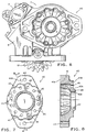
- Fig. 1 is a perspective view of a power take-off unit including an improved bearing cap in accordance with this invention.
- Fig. 2 is a side elevational view of the power take-off unit and bearing cap illustrated in Fig. 1.
- Fig. 3 is an elevational view of the inner side of the bearing cap illustrated in Fig. 2.
- Fig. 4 is a sectional elevational view of the bearing cap illustrated in Fig. 3 taken along line 4-4.
- Fig. 5 is a perspective view of a prior art driven accessory adapted to be directly mounted on the bearing cap illustrated in Figs. 1 through 4.
- Fig. 6 is a side elevational view of the power take-off unit and bearing cap illustrated in Fig. 1 having a two bolt type mounting flange adapter mounted thereon.
- Fig. 7 is an elevational view of the inner side of the two bolt type mounting flange adapter illustrated in Fig. 6.
- Fig. 8 is a sectional elevational view of the two bolt type mounting flange adapter illustrated in Figs. 6 and 7 taken along line 8-8 of Fig. 7.
- Fig. 9 is a side elevational view of the power take-off unit and bearing cap illustrated in Fig. 1 having a four bolt type mounting flange adapter mounted thereon.
- Fig. 10 is an elevational view of the inner side of the four bolt type mounting flange adapter illustrated in Fig. 9.
- Fig. 11 is a sectional elevational view of the four bolt type mounting flange adapter illustrated in Figs. 9 and 10 taken along line 11-11 of Fig. 10.
- Fig. 12 is an elevational view of a prior art bearing cap.
- the power take-off unit 10 includes a rigid housing 11 which contains an input gear 12 and an output shaft 13.
- the input gear 12 is adapted to be rotatably driven by an engine (not shown) of a vehicle in a conventional manner.
- the output shaft 13 is adapted to be connected to rotatably drive a driven accessory (not shown).
- the output shaft may be hollow and cylindrical in shape, having an inner splined surface for facilitating a rotatable driving connection with the driven accessory.
- the gear set is conventional in the art and provides one or more predetermined speed reduction gear ratios between the input gear 12 and the output shaft 13.
- a conventional shifting mechanism 14 may be provided for selecting one of the plurality of gear ratios for use.
- the gear set may also include a clutch for selectively disconnecting the output shaft 13 from the input gear 12 for intermittent operation of the driven accessory.
- the input gear 12 is supported for rotation on a non-rotatable idler shaft 15 contained with the housing 11 of the power take-off unit 10.
- the ends of the non-rotatable idler shaft 15 are supported within respective openings 11a (only one is illustrated) formed through the housing 11 of the power take-off unit 10.
- the ends of the rotatable output shaft 13, however, are rotatably supported in annular bearings (not shown) mounted within the housing 11 of the power take-off unit 10.
- the opposed sides of the housing 11 of the power take-off unit are open, and respective bearing caps are provided for supporting the annular bearings and, therefore, ends of the output shaft 13.
- One of the bearing caps, indicated generally at 20, is the subject of this invention.
- the structure of the bearing cap 20 will be explained in detail below.
- the other bearing cap (not shown) is conventional in the art and forms no part of this invention.
- the bearing cap 20 includes a body 21 having an inner side 21a and an outer side 21b.
- the inner side 21a faces toward the power take-off unit 10 and the outer side 21b faces toward the driven accessory.
- a relatively large central opening 22 is formed through the body 21 of the bearing cap 20.
- the central opening 22 extends co-axially with a first axis A1 (see Fig. 3) defined through the power take-off unit 10.
- the output shaft 13 extends through the central opening 22 co-axially with the first axis A1.
- a recess 22a is formed in the outer side 21b of the body 21 about the central opening 22.
- the recess 22a also extends co-axially with the first axis A1. The purpose of the recess 22a will be explained below.
- a hollow annular protrusion 23 is formed on the inner side 21a of the body 21 about the central opening 22.
- the protrusion 23 is defined by inner and outer circumferential surfaces 23a and 23b, respectively.
- the inner circumferential surface 23 extends co-axially with the first axis A1 and, therefore with the central opening 22 and the output shaft 13.
- the outer circumferential surface 23b extends co-axially with a second axis A2 (see Fig. 3) which is offset from the first axis A1.
- the purpose of the hollow annular protrusion 23 and for the eccentricity between the inner and outer surfaces 23a and 23b thereof will be explained below.
- a first plurality of relatively small apertures 25 is formed through the body 21 of the bearing cap 20 about the periphery thereof.
- the first apertures 25 are preferably spaced equidistantly from one another and from the second axis A2 so as to define the four corners of a square, although such spacing is not required.
- the first apertures 25 are non-threaded and are provided to permit threaded fasteners 26 to extend therethrough into engagement with corresponding threaded apertures (not shown) formed in the housing 11 of the power take-off unit 10. In this manner, the bearing cap 20 may be secured to the housing 11 of the power take-off unit 10.
- recesses 25a may be formed in the outer side 21b of the body 21 about each of the first apertures 25 to receive enlarged head portions of the threaded fasteners 26.
- a second plurality of relatively small apertures 27 is also formed through the body 21 of the bearing cap 20 about the periphery thereof.
- the second apertures 27 are preferably spaced equidistantly from one another and from the first axis A1 so as to define the three corners of an equilateral triangle, although such spacing is not required.
- the second apertures 27 are threaded and are provided for a purpose which will be explained below.
- the end of the housing 11 of the power take-off unit 10 upon which the bearing cap 20 is mounted is formed having an enlarged opening (not shown).
- the inner diameter of that enlarged opening is slightly larger than the outer diameter of the outer circumferential surface 23b of the annular protrusion 23.
- the bearing cap 20 is installed on the housing 11 by inserting and journalling the protrusion 23 within the opening.
- the second axis A2 defined by the outer circumferential surface 23b of the annular protrusion 23 is offset from the first axis A1 defined central opening 22.
- the first axis A1 can be positioned as desired relative to the second axis A2 simply by rotating the bearing cap 20 relative to the housing 11.
- This known structure is provided to accommodate differing positions of the output shaft 13 resulting from interchanging of the specific gears which make up the gear set of the power take-off unit 10.
- the threaded fasteners 26 may be used to secure it to the housing.
- the bearing cap 20 When installed on the housing 11, the bearing cap 20 is adapted to support a driven accessory on the outer side 21b thereof.
- the driven accessory may, for example, be embodied as a hydraulic pump, indicated generally at 30 in Fig. 5.
- a mounting flange 31 is secured to the pump 30 to permit it to be mounted on the bearing cap 20.
- the illustrated mounting flange 31 has four openings 32 formed therethrough, each of which is generally shaped as a clover-leaf. This mounting arrangement, often referred to as the Chelsea Special mounting flange, is well known in the art.
- the spacing of the four openings 32 in the Chelsea Special mounting flange 31 corresponds to the spacing of the four apertures 25 formed through the bearing cap 20.
- elongated threaded studs see Fig.
- Threaded fasteners 26 may be used as the threaded fasteners 26 discussed above to secure not only the bearing cap 20 to the housing 11 of the power take-off unit 10, but also the mounting flange 31 to the bearing cap 20. Threaded nuts (not shown) may be used with the studs 26 for this purposes.
- the clover-leaf shape of the openings 32 facilitates the co-axial alignment of the axis of the input shaft (not shown) of the pump 30 with the output shaft 13 of the power take-off unit 10.
- the second plurality of apertures 27 is not used.
- mounting flanges having openings formed therethrough which do not correspond in number or location with the first plurality of apertures 25.
- These other mounting flanges cannot be secured to the bearing cap 20 by the same threaded fasteners 26 used to secure the bearing cup 20 to the housing 11 of the power take-off unit 10.
- Two important mounting flange arrangements are set forth in the Society Of Automotive Engineers Standard J744 dated July, 1988. These two mounting flange arrangements are generally identified as either a two bolt type or a four bolt type. In the two bolt type, the mounting flange of the driven accessory has two bolt holes formed therethrough. Similarly, in the four bolt type, the mounting flange of the driven accessory has four bolt holes formed therethrough. In both cases, the mounting flange of the driven accessory is not compatible with the bearing cap 20 discussed above.
- this invention contemplates the use of a mounting flange adapter between the bearing cap 20 and the driven accessory.
- a first embodiment of such a mounting flange adapter indicated generally at 40 in Figs. 6, 7, and 8, is adapted for use with the two bolt type mounting flange.
- a second embodiment of such a mounting flange adapter indicated generally at 50 in Figs. 9, 10, and 11, is adapted for use with the four bolt type mounting flange.
- the two bolt type mounting flange adapter 40 includes a body 41 having an inner side 41a and an outer side 41b.
- the inner side 41a faces toward the power take-off unit 10 and the outer side 41b faces toward the driven accessory.
- a relatively large central opening 42 is formed through the body 41 of the mounting flange adapter 40.
- the central opening 42 extends co-axially with the first axis A1 defined through the power take-off unit 10 when the mounting flange adapter 40 is installed on the bearing cap 20.
- the output shaft 13 extends through the central opening 42 co-axially with the first axis A1.
- An annular protrusion 43 is formed on the inner side 41b of the body 41 about the central opening 42.
- the protrusion 43 has an outer circumferential surface 43a which is slightly smaller in diameter than the inner diameter defined by the annular recess 22a formed about the central opening 22 of the bearing cap 20.
- the body 41 of the mounting flange adapter 40 further includes a pair of bolt holes 44 formed through the opposed ends thereof. As discussed above, the two bolt holes 44 are arranged to be co-axial with two corresponding bolt holes formed through the mounting flange (not shown) of the driven accessory.
- a plurality of relatively small apertures 45 are formed through the body 41 of the mounting flange adapter 40 about the annular protrusion 43.
- twelve equidistantly spaced apertures 45 are formed through the body 41, although more or less may be provided.
- the apertures 45 are radially positioned such that three of such apertures 45 can be simultaneously aligned with the three threaded apertures 27 formed through the bearing cap 20. Consequently, three threaded fasteners (not shown) may be used to secure the mounting flange adapter 40 to the bearing cap 20.
- mounting flange adapter 40 can be secured to the bearing cap 20 in any one of twelve different relative rotational positions.
- maximum flexibility is provided in adjusting the position of the driven accessory relative to the bearing cap 20 and the power take-off unit 10.
- the four bolt type mounting flange adapter 50 includes a body 51 having an inner side 51a and an outer side 51b.
- the inner side 51a faces toward the power take-off unit 10 and the outer side 51b faces toward the driven accessory.
- a relatively large central opening 52 is formed through the body 51 of the mounting flange adapter 50.
- the central opening 52 extends co-axially with the first axis A1 defined through the power take-off unit 10 when the mounting flange adapter 50 is installed on the bearing cap 20.
- the output shaft 13 extends through the central opening 52 co-axially with the first axis A1.
- An annular protrusion 53 is formed on the inner side 51b of the body 51 about the central opening 52.
- the protrusion 53 has an outer circumferential surface 53a which is slightly smaller in diameter than the inner diameter defined by the annular recess 22a formed about the central opening 22 of the bearing cap 20.
- the body 51 of the mounting flange adapter 50 further includes four bolt holes 54 formed through the opposed ends thereof. As discussed above, the four bolt holes 54 are arranged to be co-axial with four corresponding bolt holes formed through the mounting flange (not shown) of the driven accessory.
- a plurality of relatively small apertures 55 are formed through the body 51 of the mounting flange adapter 50 about the annular protrusion 53.
- twelve equidistantly spaced apertures 55 are formed through the body 51, although more or less may be provided.
- the apertures 55 are radially positioned such that three of such apertures 55 can be simultaneously aligned with the three threaded apertures 27 formed through the bearing cap 20. Consequently, three threaded fasteners (not shown) may be used to secure the mounting flange adapter 50 to the bearing cap 20.
- the mounting flange adapter 50 can be secured to the bearing cap 20 in any one of twelve different relative rotational positions.
- maximum flexibility is provided in adjusting the position of the driven accessory relative to the bearing cap 20 and the power take-off unit 10.
- the bearing cap 20 is initially installed on the housing 11 of the power take-off unit 10 and oriented in such a manner that the central opening 22 and the first axis A1 are co-axially aligned with the output shaft 13. As discussed above, the three apertures 27 formed through the bearing cap 20 are located equidistantly from the first axis A1. Thus, when either of the mounting flange adapters 40 and 50 is mounted on the bearing cap 20, the central openings therethrough 42 and 52, respectively, are also co-axially aligned with the first axis A1. Such mounting flange adapters 40 and 50 can be rotated to a number of different orientations relative to the bearing cap 20 while maintaining this co-axial relationship with the first axis A1.
- the mounting flange adapters 40 and 50 can also be used in conjunction with conventional bearing caps, such as generally illustrated at 60 in Fig. 12.
- the conventional bearing cap 60 includes a body 61 having a central opening 62 and four peripheral apertures 63 formed therethrough.
- the central opening 62 extends co-axially with an axis A3.
- the four apertures 63 are spaced equidistantly from one another and from the axis A3 so as to define the four corners of a square.
- the apertures 45 and 55 of the mounting flange adapters 40 and 50 are radially positioned such that three of such apertures 45 and 55 can be simultaneously aligned with the three threaded apertures 27 formed through the bearing cap 20.
- the apertures 45 and 55 are radially positioned such that four of such apertures 45 and 55 can be simultaneously aligned with the four apertures 63 formed through the conventional bearing cap 60. Consequently, four threaded fasteners (not shown) may be used to secure either of the mounting flange adapters 40 or 50 to the conventional bearing cap 60. It will be appreciated that the mounting flange adapters 40 and 50 can be secured to the conventional bearing cap 60 in any one of twelve different relative rotational positions.
- an important aspect of the mounting flange adapters 40 and 50 is that the apertures 45 and 55 formed therethrough are capable of use with bearing caps 20 and 60 having differing numbers of corresponding apertures 27 and 63, respectively.
- this can be achieved by providing that the number of apertures 45 and 55 formed through the mounting flange adapters 40 and 50 (twelve in the illustrated embodiment) be equal to the product of the number of apertures formed through each of the bearing caps 20 and 60 (three and four in the illustrated embodiment) with which it is to be used.
Abstract
Description
- This invention relates in general to power take-off units and in particular to an improved structure for a bearing cap for use with a power take-off unit. This invention also relates to an improved structure for a pump mounting flange for use with a power take-off unit.
- Power take-off units are well known mechanical devices which are commonly used on engine driven vehicles for rotatably driving one or more driven accessories, often for industrial and agricultural purposes. In general, a power take-off unit selectively provides a rotatable driving connection between the engine of the vehicle and the driven accessory. To accomplish this, a typical power take-off unit includes an input gear, an output shaft, and a gear set connected between the input gear and the output shaft. The input gear is adapted to be rotatably driven by the vehicle engine, while the output shaft is adapted to be connected to rotatably drive the driven accessory. The gear set provides one or more predetermined speed reduction gear ratios between the input gear and the output shaft. The gear set may also include a clutch for selectively disconnecting the output shaft from the input gear for intermittent operation of the driven accessory.
- All of the above components of the power take-off unit are contained within a rigid housing. The input gear is rotatably supported within the housing such that a portion of the input gear extends outwardly through an opening formed through the housing. The housing of the power take-off unit is usually mounted about an opening formed through a case of a transmission of the vehicle. The outwardly extending portion of the input gear extends through the transmission case opening into meshing engagement with one of the transmission gears driven by the vehicle engine. As a result, the input gear of the power take-off unit is constantly rotatably driven by the transmission gear.
- The input gear is usually supported for rotation on a non-rotatable idler shaft contained with the housing of the power take-off unit. The ends of the non-rotatable idler shaft are supported within respective openings formed through the housing of the power take-off unit. The ends of the rotatable output shaft, however, are rotatably supported in annular bearings mounted within the housing of the power take-off unit. To facilitate assembly and maintenance, the opposed sides of the housing of the power take-off unit are open, and respective bearing caps are provided for supporting the annular bearings and, therefore, the ends of the output shaft. The bearing caps have central openings formed therethrough which respectively support the annular roller bearings which, in turn, rotatably support the ends of the output shaft. The bearing caps are themselves secured to the housing of the power take-off unit by threaded fasteners which extend through peripheral apertures formed therethrough. In the past, four of such peripheral apertures were usually provided in the bearing cap to accommodate four threaded fasteners.
- In many power take-off unit applications, the driven accessory is mounted directly on the housing of the power take-off unit. In those direct mount applications, a mounting surface for the driven accessory is provided on the exterior surface of one of the bearing caps, and a corresponding mounting flange is provided on the driven accessory. A plurality of peripheral apertures are formed through the mounting flange, through which respective threaded fasteners extend. The threaded fasteners secure the driven accessory to the bearing cap which, in turn, is secured to the housing of the power take-off unit.
- In some instances, the mounting flange peripheral apertures correspond in number and location to the bearing cap peripheral apertures. In those instances, the four threaded fasteners mentioned above can extend not only through the four bearing cap peripheral apertures, but also through the four mounting flange peripheral apertures. Thus, the same four threaded fasteners can secure not only the bearing cap to the housing of the power take-off unit, but also the driven accessory to the bearing cap.
- In other instances, however, the number and location of the mounting flange peripheral apertures are different from the bearing cap peripheral apertures. In those instances, the bearing cap must be formed having additional peripheral apertures to accommodate the threaded fasteners which secure the driven accessory to the bearing cap. As a result, a wide variety of bearings caps are necessary to accommodate a wide variety of mounting flanges. The lack of a single bearing cap structure which can accommodate a variety of mounting flange structures is undesirable for several readily apparent reasons. Thus, it would be desirable to provide an improved structure for a bearing cap for a power take-off unit which can accommodate a variety of mounting flange structures.
- Separate and apart from the desirability of providing a single bearing cap structure which can accommodate a variety of mounting flange structures, it has also been found that existing bearing cap structures do not provide sufficient flexibility in adjusting the position of the driven accessory relative to the bearing cap and the power take-off unit. Inasmuch as the power take-off unit is secured to the transmission of the vehicle, it will be appreciated that the physical space available in that area of the vehicle is usually limited. It has been found that some driven accessories cannot be mounted on some vehicles because of a lack of clearance. Thus, it would also be desirable to provide an improved structure for a bearing cap for a power take-off unit which provides greater flexibility in adjusting the position of the driven accessory relative to the bearing cap and the power take-off unit.
- This invention relates to an improved structure for a bearing cap for use with a power take-off unit which can accommodate a variety of mounting flange structures and which provides greater flexibility in adjusting the position of the driven accessory relative to the bearing cap and the power take-off unit. The bearing cap includes a body having a relatively large central opening formed therethrough. A recess is formed in one side of the body about the central opening. A hollow annular protrusion is formed on the body about the central opening. A first plurality of relatively small apertures is formed through the body of the bearing cap about the periphery thereof. The first apertures are provided to secure the bearing cap to the housing of the power take-off unit and for securing certain types of driven accessory mounting flanges to the bearing cap. A second plurality of relatively small apertures is also formed through the body of the bearing cap about the periphery thereof. The second apertures are provided for securing mounting flanges adapters to the bearing cap to permit certain other types of driven accessory mounting flanges to be secured thereto. Different bearing caps are provided with differing numbers of these second apertures. The mounting flange adapters have a plurality of apertures formed therethrough. In the preferred embodiment, the number of apertures formed through the mounting flange adapter is equal to the product of the number of apertures formed through the bearing caps with which it is to be used.
- Various objects and advantages of this invention will become apparent to those skilled in the art from the following detailed description of the preferred embodiments, when read in light of the accompanying drawings.
- Fig. 1 is a perspective view of a power take-off unit including an improved bearing cap in accordance with this invention.
- Fig. 2 is a side elevational view of the power take-off unit and bearing cap illustrated in Fig. 1.
- Fig. 3 is an elevational view of the inner side of the bearing cap illustrated in Fig. 2.
- Fig. 4 is a sectional elevational view of the bearing cap illustrated in Fig. 3 taken along line 4-4.
- Fig. 5 is a perspective view of a prior art driven accessory adapted to be directly mounted on the bearing cap illustrated in Figs. 1 through 4.
- Fig. 6 is a side elevational view of the power take-off unit and bearing cap illustrated in Fig. 1 having a two bolt type mounting flange adapter mounted thereon.
- Fig. 7 is an elevational view of the inner side of the two bolt type mounting flange adapter illustrated in Fig. 6.
- Fig. 8 is a sectional elevational view of the two bolt type mounting flange adapter illustrated in Figs. 6 and 7 taken along line 8-8 of Fig. 7.
- Fig. 9 is a side elevational view of the power take-off unit and bearing cap illustrated in Fig. 1 having a four bolt type mounting flange adapter mounted thereon.
- Fig. 10 is an elevational view of the inner side of the four bolt type mounting flange adapter illustrated in Fig. 9.
- Fig. 11 is a sectional elevational view of the four bolt type mounting flange adapter illustrated in Figs. 9 and 10 taken along line 11-11 of Fig. 10.
- Fig. 12 is an elevational view of a prior art bearing cap.
- Referring now to the drawings, there is illustrated in Fig. 1 a power take-off unit, indicated generally at 10, in accordance with this invention. The basic structure and mode of operation of the power take-off
unit 10 is well known in the art, and only those portions of the power take-offunit 10 which are necessary for a complete understanding of this invention will be described. The power take-offunit 10 includes a rigid housing 11 which contains aninput gear 12 and anoutput shaft 13. Theinput gear 12 is adapted to be rotatably driven by an engine (not shown) of a vehicle in a conventional manner. Theoutput shaft 13 is adapted to be connected to rotatably drive a driven accessory (not shown). The output shaft may be hollow and cylindrical in shape, having an inner splined surface for facilitating a rotatable driving connection with the driven accessory. - Between the
input gear 12 and theoutput shaft 13, a gear set (not shown) is provided. The gear set is conventional in the art and provides one or more predetermined speed reduction gear ratios between theinput gear 12 and theoutput shaft 13. Aconventional shifting mechanism 14 may be provided for selecting one of the plurality of gear ratios for use. The gear set may also include a clutch for selectively disconnecting theoutput shaft 13 from theinput gear 12 for intermittent operation of the driven accessory. - The
input gear 12 is supported for rotation on a non-rotatableidler shaft 15 contained with the housing 11 of the power take-offunit 10. The ends of the non-rotatableidler shaft 15 are supported within respective openings 11a (only one is illustrated) formed through the housing 11 of the power take-offunit 10. The ends of therotatable output shaft 13, however, are rotatably supported in annular bearings (not shown) mounted within the housing 11 of the power take-offunit 10. The opposed sides of the housing 11 of the power take-off unit are open, and respective bearing caps are provided for supporting the annular bearings and, therefore, ends of theoutput shaft 13. One of the bearing caps, indicated generally at 20, is the subject of this invention. The structure of thebearing cap 20 will be explained in detail below. The other bearing cap (not shown) is conventional in the art and forms no part of this invention. - Referring now to Figs. 2, 3, and 4, the structure of the
bearing cap 20 will be explained in detail. The bearingcap 20 includes abody 21 having aninner side 21a and an outer side 21b. When thebearing cap 20 is installed on the housing 11 of the power take-offunit 10, theinner side 21a faces toward the power take-offunit 10 and the outer side 21b faces toward the driven accessory. A relatively largecentral opening 22 is formed through thebody 21 of thebearing cap 20. Thecentral opening 22 extends co-axially with a first axis A1 (see Fig. 3) defined through the power take-offunit 10. When thebearing cap 20 is installed on the housing 11 of the power take-offunit 10, theoutput shaft 13 extends through thecentral opening 22 co-axially with the first axis A1. Arecess 22a is formed in the outer side 21b of thebody 21 about thecentral opening 22. Therecess 22a also extends co-axially with the first axis A1. The purpose of therecess 22a will be explained below. - A hollow
annular protrusion 23 is formed on theinner side 21a of thebody 21 about thecentral opening 22. Theprotrusion 23 is defined by inner and outercircumferential surfaces circumferential surface 23 extends co-axially with the first axis A1 and, therefore with thecentral opening 22 and theoutput shaft 13. However, the outercircumferential surface 23b extends co-axially with a second axis A2 (see Fig. 3) which is offset from the first axis A1. The purpose of the hollowannular protrusion 23 and for the eccentricity between the inner andouter surfaces - A first plurality of relatively
small apertures 25 is formed through thebody 21 of thebearing cap 20 about the periphery thereof. Thefirst apertures 25 are preferably spaced equidistantly from one another and from the second axis A2 so as to define the four corners of a square, although such spacing is not required. Thefirst apertures 25 are non-threaded and are provided to permit threadedfasteners 26 to extend therethrough into engagement with corresponding threaded apertures (not shown) formed in the housing 11 of the power take-offunit 10. In this manner, the bearingcap 20 may be secured to the housing 11 of the power take-offunit 10. If desired, recesses 25a may be formed in the outer side 21b of thebody 21 about each of thefirst apertures 25 to receive enlarged head portions of the threadedfasteners 26. - A second plurality of relatively
small apertures 27 is also formed through thebody 21 of thebearing cap 20 about the periphery thereof. Thesecond apertures 27 are preferably spaced equidistantly from one another and from the first axis A1 so as to define the three corners of an equilateral triangle, although such spacing is not required. Thesecond apertures 27 are threaded and are provided for a purpose which will be explained below. - As is known in the art, the end of the housing 11 of the power take-off
unit 10 upon which thebearing cap 20 is mounted is formed having an enlarged opening (not shown). The inner diameter of that enlarged opening is slightly larger than the outer diameter of the outercircumferential surface 23b of theannular protrusion 23. Thus, the bearingcap 20 is installed on the housing 11 by inserting and journalling theprotrusion 23 within the opening. As mentioned above, the second axis A2 defined by the outercircumferential surface 23b of theannular protrusion 23 is offset from the first axis A1 definedcentral opening 22. As a result, the first axis A1 can be positioned as desired relative to the second axis A2 simply by rotating thebearing cap 20 relative to the housing 11. This known structure is provided to accommodate differing positions of theoutput shaft 13 resulting from interchanging of the specific gears which make up the gear set of the power take-offunit 10. When a desired relative position of thebearing cap 20 is achieved, the threadedfasteners 26 may be used to secure it to the housing. - When installed on the housing 11, the bearing
cap 20 is adapted to support a driven accessory on the outer side 21b thereof. The driven accessory may, for example, be embodied as a hydraulic pump, indicated generally at 30 in Fig. 5. As discussed above, a mountingflange 31 is secured to thepump 30 to permit it to be mounted on thebearing cap 20. The illustrated mountingflange 31 has fouropenings 32 formed therethrough, each of which is generally shaped as a clover-leaf. This mounting arrangement, often referred to as the Chelsea Special mounting flange, is well known in the art. The spacing of the fouropenings 32 in the ChelseaSpecial mounting flange 31 corresponds to the spacing of the fourapertures 25 formed through thebearing cap 20. Thus, elongated threaded studs (see Fig. 1) may be used as the threadedfasteners 26 discussed above to secure not only thebearing cap 20 to the housing 11 of the power take-offunit 10, but also the mountingflange 31 to thebearing cap 20. Threaded nuts (not shown) may be used with thestuds 26 for this purposes. The clover-leaf shape of theopenings 32 facilitates the co-axial alignment of the axis of the input shaft (not shown) of thepump 30 with theoutput shaft 13 of the power take-offunit 10. - When a
pump 30 having a ChelseaSpecial mounting flange 31 is mounted on the bearingcup 20, the second plurality ofapertures 27 is not used. However, there are several other types of mounting flanges having openings formed therethrough which do not correspond in number or location with the first plurality ofapertures 25. These other mounting flanges cannot be secured to thebearing cap 20 by the same threadedfasteners 26 used to secure the bearingcup 20 to the housing 11 of the power take-offunit 10. Two important mounting flange arrangements are set forth in the Society Of Automotive Engineers Standard J744 dated July, 1988. These two mounting flange arrangements are generally identified as either a two bolt type or a four bolt type. In the two bolt type, the mounting flange of the driven accessory has two bolt holes formed therethrough. Similarly, in the four bolt type, the mounting flange of the driven accessory has four bolt holes formed therethrough. In both cases, the mounting flange of the driven accessory is not compatible with thebearing cap 20 discussed above. - Thus, to accommodate mounting flanges of the two bolt type and four bolt type, this invention contemplates the use of a mounting flange adapter between the bearing
cap 20 and the driven accessory. A first embodiment of such a mounting flange adapter, indicated generally at 40 in Figs. 6, 7, and 8, is adapted for use with the two bolt type mounting flange. A second embodiment of such a mounting flange adapter, indicated generally at 50 in Figs. 9, 10, and 11, is adapted for use with the four bolt type mounting flange. - Referring first to Figs. 6, 7, and 8, the two bolt type mounting
flange adapter 40 includes abody 41 having aninner side 41a and anouter side 41b. When the mountingflange adapter 40 is installed on thebearing cap 20, theinner side 41a faces toward the power take-offunit 10 and theouter side 41b faces toward the driven accessory. A relatively largecentral opening 42 is formed through thebody 41 of the mountingflange adapter 40. Thecentral opening 42 extends co-axially with the first axis A1 defined through the power take-offunit 10 when the mountingflange adapter 40 is installed on thebearing cap 20. Thus, when the mountingflange adapter 40 is installed on thebearing cap 20, theoutput shaft 13 extends through thecentral opening 42 co-axially with the first axis A1. - An
annular protrusion 43 is formed on theinner side 41b of thebody 41 about thecentral opening 42. Theprotrusion 43 has an outercircumferential surface 43a which is slightly smaller in diameter than the inner diameter defined by theannular recess 22a formed about thecentral opening 22 of thebearing cap 20. Thus, the mountingflange adapter 40 is installed on thebearing cap 20 by inserting and journalling theprotrusion 43 within therecess 22a. Thebody 41 of the mountingflange adapter 40 further includes a pair of bolt holes 44 formed through the opposed ends thereof. As discussed above, the twobolt holes 44 are arranged to be co-axial with two corresponding bolt holes formed through the mounting flange (not shown) of the driven accessory. - A plurality of relatively
small apertures 45 are formed through thebody 41 of the mountingflange adapter 40 about theannular protrusion 43. In the preferred embodiment, twelve equidistantly spacedapertures 45 are formed through thebody 41, although more or less may be provided. Theapertures 45 are radially positioned such that three ofsuch apertures 45 can be simultaneously aligned with the three threadedapertures 27 formed through thebearing cap 20. Consequently, three threaded fasteners (not shown) may be used to secure the mountingflange adapter 40 to thebearing cap 20. Inasmuch as there are twelve equidistantly spacedapertures 45 formed through the mountingflange adapter 40, it will be appreciated that the mountingflange adapter 40 can be secured to thebearing cap 20 in any one of twelve different relative rotational positions. Thus, maximum flexibility is provided in adjusting the position of the driven accessory relative to thebearing cap 20 and the power take-offunit 10. - Referring now to Figs. 9, 10, and 11, the four bolt type mounting
flange adapter 50 includes abody 51 having an inner side 51a and an outer side 51b. When the mountingflange adapter 50 is installed on thebearing cap 20, the inner side 51a faces toward the power take-offunit 10 and the outer side 51b faces toward the driven accessory. A relatively largecentral opening 52 is formed through thebody 51 of the mountingflange adapter 50. Thecentral opening 52 extends co-axially with the first axis A1 defined through the power take-offunit 10 when the mountingflange adapter 50 is installed on thebearing cap 20. Thus, when the mountingflange adapter 50 is installed on thebearing cap 20, theoutput shaft 13 extends through thecentral opening 52 co-axially with the first axis A1. - An
annular protrusion 53 is formed on the inner side 51b of thebody 51 about thecentral opening 52. Theprotrusion 53 has an outercircumferential surface 53a which is slightly smaller in diameter than the inner diameter defined by theannular recess 22a formed about thecentral opening 22 of thebearing cap 20. Thus, the mountingflange adapter 50 is installed on thebearing cap 20 by inserting and journalling theprotrusion 53 within therecess 22a. Thebody 51 of the mountingflange adapter 50 further includes fourbolt holes 54 formed through the opposed ends thereof. As discussed above, the fourbolt holes 54 are arranged to be co-axial with four corresponding bolt holes formed through the mounting flange (not shown) of the driven accessory. - A plurality of relatively
small apertures 55 are formed through thebody 51 of the mountingflange adapter 50 about theannular protrusion 53. In the preferred embodiment, twelve equidistantly spacedapertures 55 are formed through thebody 51, although more or less may be provided. Theapertures 55 are radially positioned such that three ofsuch apertures 55 can be simultaneously aligned with the three threadedapertures 27 formed through thebearing cap 20. Consequently, three threaded fasteners (not shown) may be used to secure the mountingflange adapter 50 to thebearing cap 20. Inasmuch as there are twelve equidistantly spacedapertures 55 formed through the mountingflange adapter 50, it will be appreciated that the mountingflange adapter 50 can be secured to thebearing cap 20 in any one of twelve different relative rotational positions. Thus, as with the two bolt type mountingflange adapter 50 discussed above, maximum flexibility is provided in adjusting the position of the driven accessory relative to thebearing cap 20 and the power take-offunit 10. - To briefly review, the bearing
cap 20 is initially installed on the housing 11 of the power take-offunit 10 and oriented in such a manner that thecentral opening 22 and the first axis A1 are co-axially aligned with theoutput shaft 13. As discussed above, the threeapertures 27 formed through thebearing cap 20 are located equidistantly from the first axis A1. Thus, when either of the mountingflange adapters bearing cap 20, the central openings therethrough 42 and 52, respectively, are also co-axially aligned with the first axis A1. Such mountingflange adapters bearing cap 20 while maintaining this co-axial relationship with the first axis A1. - The mounting
flange adapters conventional bearing cap 60 includes abody 61 having acentral opening 62 and fourperipheral apertures 63 formed therethrough. Thecentral opening 62 extends co-axially with an axis A3. The fourapertures 63 are spaced equidistantly from one another and from the axis A3 so as to define the four corners of a square. - As discussed above, the
apertures flange adapters such apertures apertures 27 formed through thebearing cap 20. Similarly, theapertures such apertures apertures 63 formed through theconventional bearing cap 60. Consequently, four threaded fasteners (not shown) may be used to secure either of the mountingflange adapters conventional bearing cap 60. It will be appreciated that the mountingflange adapters conventional bearing cap 60 in any one of twelve different relative rotational positions. - Thus, an important aspect of the mounting
flange adapters apertures caps corresponding apertures apertures flange adapters 40 and 50 (twelve in the illustrated embodiment) be equal to the product of the number of apertures formed through each of the bearing caps 20 and 60 (three and four in the illustrated embodiment) with which it is to be used. Such an arrangement will insure not only that the mountingflange adapters flange adapters apertures apertures flange adapters - In accordance with the provisions of the patent statutes, the principle and mode of operation of this invention has been explained and illustrated in its preferred embodiments. However, it must be understood that this invention may be practiced otherwise than as specifically explained and illustrated without departing from its spirit or scope.
Claims (5)
- A bearing cup for use in a power take-off unit comprising:
a body having a relatively large central opening formed therethrough and a protrusion formed about said central opening, said central opening extending co-axially with a first axis;
a first plurality of apertures formed through said body, said first plurality of apertures being spaced equidistantly from a second axis to permit said body to be secured to the power take-off unit; and
a second plurality of apertures formed through said body, said second plurality of apertures being spaced equidistantly from said first axis. - The bearing cap defined in Claim 1 wherein said first axis is substantially parallel to and offset offset from said second axis.
- The bearing cap defined in Claim 1 wherein said body includes a first side on which said protrusion is formed, and an opposed second side, and wherein an annular recess is formed in said second side of said body about said central opening.
- The bearing cap defined in Claim 1 wherein said first plurality of apertures includes four apertures equidistantly spaced from one another.
- The bearing cap defined in Claim 1 wherein said second plurality of apertures includes three apertures equidistantly spaced from one another.
Applications Claiming Priority (2)
| Application Number | Priority Date | Filing Date | Title |
|---|---|---|---|
| US08/227,971 US5645363A (en) | 1994-04-15 | 1994-04-15 | Bearing cap and pump mounting flange for power take-off unit |
| US227971 | 1994-04-15 |
Publications (2)
| Publication Number | Publication Date |
|---|---|
| EP0677416A1 true EP0677416A1 (en) | 1995-10-18 |
| EP0677416B1 EP0677416B1 (en) | 1998-08-19 |
Family
ID=22855217
Family Applications (1)
| Application Number | Title | Priority Date | Filing Date |
|---|---|---|---|
| EP95302353A Expired - Lifetime EP0677416B1 (en) | 1994-04-15 | 1995-04-10 | Bearing cap and pump mounting flange for power take-off unit |
Country Status (9)
| Country | Link |
|---|---|
| US (1) | US5645363A (en) |
| EP (1) | EP0677416B1 (en) |
| JP (1) | JPH07285352A (en) |
| KR (1) | KR100374457B1 (en) |
| AU (1) | AU684610B2 (en) |
| CA (1) | CA2147093A1 (en) |
| DE (1) | DE69504119T2 (en) |
| ES (1) | ES2123208T3 (en) |
| TW (1) | TW320607B (en) |
Cited By (9)
| Publication number | Priority date | Publication date | Assignee | Title |
|---|---|---|---|---|
| EP0993983A1 (en) * | 1998-10-16 | 2000-04-19 | Interpump Hydraulics S.p.A. | Power take-off adapter |
| WO2002048517A2 (en) * | 2000-12-12 | 2002-06-20 | Scania Cv Ab (Publ) | Housing for a turbo compound unit and a turbo compound unit and combustion engine |
| WO2002048519A2 (en) * | 2000-12-12 | 2002-06-20 | Scania Cv Ab (Publ) | Turbo compound unit and housing thereto and combustion engine including a turbo compound unit |
| WO2014111859A1 (en) * | 2013-01-15 | 2014-07-24 | Aber - Embraiagens E Comandos Hidraulicos, Antonio Bernardes, Lda | Power take-off for motor vehicles and respective use |
| WO2019185264A1 (en) * | 2018-03-29 | 2019-10-03 | Zf Friedrichshafen Ag | Auxiliary power take-off assembly |
| WO2019185261A1 (en) * | 2018-03-29 | 2019-10-03 | Zf Friedrichshafen Ag | Auxiliary power take-off assembly |
| EP3964732A1 (en) * | 2020-09-04 | 2022-03-09 | SL-Technik GmbH | 3-point torque support |
| US11479116B2 (en) | 2018-03-29 | 2022-10-25 | Zf Friedrichshafen Ag | Auxiliary power take-off assembly |
| US11635231B2 (en) | 2019-09-03 | 2023-04-25 | Sl-Technik Gmbh | Rotating grate with a cleaning device for a biomass heating system |
Families Citing this family (26)
| Publication number | Priority date | Publication date | Assignee | Title |
|---|---|---|---|---|
| US5913523A (en) * | 1996-05-30 | 1999-06-22 | Selapack; Leon C. | Transmission leak repair process and plate therefor |
| WO1998031965A1 (en) * | 1997-01-16 | 1998-07-23 | American Precision Industries Inc. | Modular motor and gearhead mounting arrangement |
| US6298025B1 (en) * | 1997-05-05 | 2001-10-02 | Warner Music Group Inc. | Recording and playback of multi-channel digital audio having different resolutions for different channels |
| EP0950835B1 (en) * | 1998-04-17 | 2002-12-04 | Demag Cranes & Components GmbH | Torque transmitting coupling arrangement |
| US6224289B1 (en) | 1998-12-18 | 2001-05-01 | Kevin D. Redd | Power takeoff unit-driven unit adapter with sump lubrication |
| US7178424B2 (en) * | 2004-12-06 | 2007-02-20 | American Axle & Manufacturing, Inc. | Pinion unit in axle assembly |
| US7644962B2 (en) * | 2006-02-23 | 2010-01-12 | Salco Products Inc. | Universal attachment flange |
| KR100692287B1 (en) * | 2006-09-01 | 2007-03-12 | (주)대아펌프 | A coupling for the fire-fighting engine pump and the fire-fighting engine pump |
| US8984974B2 (en) * | 2006-12-14 | 2015-03-24 | W.S. Darley & Co. | Pump transmission with PTO gear and independently clutched impeller |
| US20080141799A1 (en) * | 2006-12-14 | 2008-06-19 | Seitz Douglas W | Dual gear pump transmission |
| US8726675B2 (en) * | 2007-09-07 | 2014-05-20 | The Boeing Company | Scalloped flexure ring |
| US20090067917A1 (en) * | 2007-09-07 | 2009-03-12 | The Boeing Company | Bipod Flexure Ring |
| EP2079152A3 (en) * | 2008-01-11 | 2011-04-13 | Goodrich Corporation | Mounting arrangement for an electrical generator |
| US8167583B2 (en) * | 2008-10-24 | 2012-05-01 | Cnh America Llc | Pump support coupler system |
| US20110162466A1 (en) * | 2009-10-07 | 2011-07-07 | Hydreco | Power take-off |
| CN102213269A (en) * | 2011-06-09 | 2011-10-12 | 许晓华 | Stamped steel type flange plate |
| US8991274B2 (en) | 2012-07-06 | 2015-03-31 | Cnh Industrial America Llc | Mounting surface of an agricultural work vehicle power takeoff system |
| PL3019774T3 (en) * | 2013-07-09 | 2017-10-31 | Sew Eurodrive Gmbh & Co | Geared motor |
| US9856753B2 (en) * | 2015-06-10 | 2018-01-02 | United Technologies Corporation | Inner diameter scallop case flange for a case of a gas turbine engine |
| DE102015223874A1 (en) * | 2015-12-01 | 2017-06-01 | Minimax Gmbh & Co. Kg | Method for producing a flange blank and a flange |
| DE102016213562B4 (en) * | 2016-07-25 | 2019-10-31 | Valeo Siemens Eautomotive Germany Gmbh | Torque transmitting shaft connection and manufacturing process, as well as powertrain, motor vehicle, program and manufacturing equipment |
| US10174794B2 (en) * | 2016-07-28 | 2019-01-08 | GM Global Technology Operations LLC | Power take-off assembly having a multiple stage clutch |
| US11142065B2 (en) * | 2017-11-30 | 2021-10-12 | Parker-Hannifin Corporation | Vibration attenuation of mating gears in a power take-off |
| US11267336B2 (en) | 2019-12-02 | 2022-03-08 | Eaton Cummins Automated Transmission Technologies, Llc | Transmission integrated power take off for commercial vehicle transmission |
| US11953032B2 (en) | 2021-02-09 | 2024-04-09 | Caterpillar Inc. | Hydraulic pump or motor with mounting configuration for increased torque |
| US20220388392A1 (en) * | 2021-06-02 | 2022-12-08 | Muncie Power Products, Inc. | Systems and methods for power takeoff attachment |
Citations (4)
| Publication number | Priority date | Publication date | Assignee | Title |
|---|---|---|---|---|
| DE976614C (en) * | 1952-09-09 | 1964-01-02 | Int Harvester Co | PTO shaft for farm tractor |
| GB2153763A (en) * | 1984-02-06 | 1985-08-29 | Dana Corp | Power take-off assembly |
| US4813290A (en) * | 1988-01-22 | 1989-03-21 | Dne Corporation | Power takeoff for motor vehicle |
| GB2261488A (en) * | 1991-11-15 | 1993-05-19 | Dana Corp | Power take-off unit |
Family Cites Families (9)
| Publication number | Priority date | Publication date | Assignee | Title |
|---|---|---|---|---|
| US2735281A (en) * | 1956-02-21 | Shrouded power take-off shaft for tractors | ||
| US2851896A (en) * | 1954-11-08 | 1958-09-16 | Cone Automatic Mach Co Inc | Tractor pump drive |
| US4478593A (en) * | 1981-06-08 | 1984-10-23 | Gordon Brown | Coupling of unrelated engine and transmission |
| FR2529030B1 (en) * | 1982-06-17 | 1985-09-27 | Labavia | IMPROVEMENTS ON ELECTRIC RETARDERS |
| US4597301A (en) * | 1984-03-30 | 1986-07-01 | Dana Corporation | Power takeoff speed control assembly |
| US4685341A (en) * | 1985-08-02 | 1987-08-11 | Kubota, Ltd. | Power transmitting apparatus for tractor |
| US4773277A (en) * | 1986-12-17 | 1988-09-27 | Dana Corporation | Self-contained power take-off |
| US4824334A (en) * | 1987-11-02 | 1989-04-25 | Ramsay Ronald D | Modular hydraulic power system |
| US5163335A (en) * | 1991-07-15 | 1992-11-17 | Patrick D. Isom | Universal starter motor assembly |
-
1994
- 1994-04-15 US US08/227,971 patent/US5645363A/en not_active Expired - Lifetime
- 1994-08-26 TW TW083107843A patent/TW320607B/zh active
-
1995
- 1995-04-10 EP EP95302353A patent/EP0677416B1/en not_active Expired - Lifetime
- 1995-04-10 DE DE69504119T patent/DE69504119T2/en not_active Expired - Fee Related
- 1995-04-10 ES ES95302353T patent/ES2123208T3/en not_active Expired - Lifetime
- 1995-04-13 CA CA002147093A patent/CA2147093A1/en not_active Abandoned
- 1995-04-13 JP JP7111082A patent/JPH07285352A/en active Pending
- 1995-04-13 AU AU16491/95A patent/AU684610B2/en not_active Ceased
- 1995-04-14 KR KR1019950008789A patent/KR100374457B1/en not_active IP Right Cessation
Patent Citations (4)
| Publication number | Priority date | Publication date | Assignee | Title |
|---|---|---|---|---|
| DE976614C (en) * | 1952-09-09 | 1964-01-02 | Int Harvester Co | PTO shaft for farm tractor |
| GB2153763A (en) * | 1984-02-06 | 1985-08-29 | Dana Corp | Power take-off assembly |
| US4813290A (en) * | 1988-01-22 | 1989-03-21 | Dne Corporation | Power takeoff for motor vehicle |
| GB2261488A (en) * | 1991-11-15 | 1993-05-19 | Dana Corp | Power take-off unit |
Non-Patent Citations (1)
| Title |
|---|
| SOCIETY OF AUTOMOTIVE ENGINEERS STANDARD J744 DATED JULY 1988 * |
Cited By (15)
| Publication number | Priority date | Publication date | Assignee | Title |
|---|---|---|---|---|
| EP0993983A1 (en) * | 1998-10-16 | 2000-04-19 | Interpump Hydraulics S.p.A. | Power take-off adapter |
| WO2002048517A2 (en) * | 2000-12-12 | 2002-06-20 | Scania Cv Ab (Publ) | Housing for a turbo compound unit and a turbo compound unit and combustion engine |
| WO2002048519A2 (en) * | 2000-12-12 | 2002-06-20 | Scania Cv Ab (Publ) | Turbo compound unit and housing thereto and combustion engine including a turbo compound unit |
| WO2002048519A3 (en) * | 2000-12-12 | 2002-08-15 | Scania Cv Abp | Turbo compound unit and housing thereto and combustion engine including a turbo compound unit |
| WO2002048517A3 (en) * | 2000-12-12 | 2002-08-15 | Scania Cv Abp | Housing for a turbo compound unit and a turbo compound unit and combustion engine |
| WO2014111859A1 (en) * | 2013-01-15 | 2014-07-24 | Aber - Embraiagens E Comandos Hidraulicos, Antonio Bernardes, Lda | Power take-off for motor vehicles and respective use |
| WO2019185264A1 (en) * | 2018-03-29 | 2019-10-03 | Zf Friedrichshafen Ag | Auxiliary power take-off assembly |
| WO2019185261A1 (en) * | 2018-03-29 | 2019-10-03 | Zf Friedrichshafen Ag | Auxiliary power take-off assembly |
| US11479117B2 (en) | 2018-03-29 | 2022-10-25 | Zf Friedrichshafen Ag | Auxiliary power take-off assembly |
| US11479116B2 (en) | 2018-03-29 | 2022-10-25 | Zf Friedrichshafen Ag | Auxiliary power take-off assembly |
| US11813938B2 (en) | 2018-03-29 | 2023-11-14 | Zf Friedrichshafen Ag | Auxiliary power take-off assembly |
| US11635231B2 (en) | 2019-09-03 | 2023-04-25 | Sl-Technik Gmbh | Rotating grate with a cleaning device for a biomass heating system |
| US11708999B2 (en) | 2019-09-03 | 2023-07-25 | Sl-Technik Gmbh | Biomass heating system with optimized flue gas treatment |
| EP3964732A1 (en) * | 2020-09-04 | 2022-03-09 | SL-Technik GmbH | 3-point torque support |
| WO2022048769A1 (en) * | 2020-09-04 | 2022-03-10 | Sl-Technik Gmbh | 3-point torque support |
Also Published As
| Publication number | Publication date |
|---|---|
| EP0677416B1 (en) | 1998-08-19 |
| TW320607B (en) | 1997-11-21 |
| ES2123208T3 (en) | 1999-01-01 |
| KR100374457B1 (en) | 2003-05-01 |
| AU684610B2 (en) | 1997-12-18 |
| AU1649195A (en) | 1995-10-26 |
| US5645363A (en) | 1997-07-08 |
| CA2147093A1 (en) | 1995-10-16 |
| KR950033151A (en) | 1995-12-22 |
| DE69504119D1 (en) | 1998-09-24 |
| JPH07285352A (en) | 1995-10-31 |
| DE69504119T2 (en) | 1998-12-24 |
Similar Documents
| Publication | Publication Date | Title |
|---|---|---|
| EP0677416B1 (en) | Bearing cap and pump mounting flange for power take-off unit | |
| US4407170A (en) | Speed change device | |
| US6699152B2 (en) | Speed reduction gear | |
| US6053838A (en) | Helical differential assembly | |
| JP5356462B2 (en) | Turning structure of industrial robot using eccentric rocking type reducer | |
| EP0548888B1 (en) | Internally meshing planetary gear structure | |
| EP0962349B1 (en) | Power transmission device | |
| US5271294A (en) | Banjo type axle housing having differential carrier support structure | |
| US6884196B1 (en) | Inter-axle differential with improved differential gear mounting arrangement | |
| US6692398B1 (en) | Simplified differential assembly | |
| US4587862A (en) | Transmission for pumps | |
| US5588931A (en) | Planetary reducer and wheel bearing unit | |
| CA1058911A (en) | Multiple power path concentric speed reducer | |
| EP1673253B1 (en) | An arrangement for driving a wheel of a vehicle, and a planet carrier | |
| US6689009B1 (en) | Compact differential assembly | |
| US20040231457A1 (en) | Automatic transmission | |
| US3960061A (en) | Mounting arrangement for a hydraulic motor | |
| US5649456A (en) | Transmission gear support structure | |
| US5255895A (en) | Gear transmission in a lifting machinery | |
| US5590571A (en) | Structure for mounting an output gear and bearing to a transmission | |
| KR0174167B1 (en) | Auto-transmission | |
| US5848950A (en) | Differential gear capable of deriving differential restriction force by frictional resistance with rotations of pinion and side gears | |
| JP3650359B2 (en) | Power system for four-wheel drive vehicles | |
| WO2000050296A1 (en) | Forward driving gear for bicycle | |
| EP0526825A1 (en) | Differential bearing cap fastener |
Legal Events
| Date | Code | Title | Description |
|---|---|---|---|
| PUAI | Public reference made under article 153(3) epc to a published international application that has entered the european phase |
Free format text: ORIGINAL CODE: 0009012 |
|
| AK | Designated contracting states |
Kind code of ref document: A1 Designated state(s): DE ES FR GB IT NL SE |
|
| 17P | Request for examination filed |
Effective date: 19960411 |
|
| 17Q | First examination report despatched |
Effective date: 19970114 |
|
| GRAG | Despatch of communication of intention to grant |
Free format text: ORIGINAL CODE: EPIDOS AGRA |
|
| GRAG | Despatch of communication of intention to grant |
Free format text: ORIGINAL CODE: EPIDOS AGRA |
|
| GRAH | Despatch of communication of intention to grant a patent |
Free format text: ORIGINAL CODE: EPIDOS IGRA |
|
| GRAH | Despatch of communication of intention to grant a patent |
Free format text: ORIGINAL CODE: EPIDOS IGRA |
|
| GRAA | (expected) grant |
Free format text: ORIGINAL CODE: 0009210 |
|
| ITF | It: translation for a ep patent filed |
Owner name: BARZANO' E ZANARDO ROMA S.P.A. |
|
| AK | Designated contracting states |
Kind code of ref document: B1 Designated state(s): DE ES FR GB IT NL SE |
|
| REF | Corresponds to: |
Ref document number: 69504119 Country of ref document: DE Date of ref document: 19980924 |
|
| ET | Fr: translation filed | ||
| REG | Reference to a national code |
Ref country code: ES Ref legal event code: FG2A Ref document number: 2123208 Country of ref document: ES Kind code of ref document: T3 |
|
| PLBE | No opposition filed within time limit |
Free format text: ORIGINAL CODE: 0009261 |
|
| STAA | Information on the status of an ep patent application or granted ep patent |
Free format text: STATUS: NO OPPOSITION FILED WITHIN TIME LIMIT |
|
| 26N | No opposition filed | ||
| REG | Reference to a national code |
Ref country code: GB Ref legal event code: 732E |
|
| REG | Reference to a national code |
Ref country code: GB Ref legal event code: IF02 |
|
| NLS | Nl: assignments of ep-patents |
Owner name: PARKER-HANNIFIN CORPORATION |
|
| REG | Reference to a national code |
Ref country code: FR Ref legal event code: TP |
|
| REG | Reference to a national code |
Ref country code: ES Ref legal event code: PC2A |
|
| PGFP | Annual fee paid to national office [announced via postgrant information from national office to epo] |
Ref country code: FR Payment date: 20030310 Year of fee payment: 9 |
|
| PGFP | Annual fee paid to national office [announced via postgrant information from national office to epo] |
Ref country code: GB Payment date: 20030313 Year of fee payment: 9 |
|
| PGFP | Annual fee paid to national office [announced via postgrant information from national office to epo] |
Ref country code: DE Payment date: 20030324 Year of fee payment: 9 |
|
| PGFP | Annual fee paid to national office [announced via postgrant information from national office to epo] |
Ref country code: NL Payment date: 20030325 Year of fee payment: 9 |
|
| PGFP | Annual fee paid to national office [announced via postgrant information from national office to epo] |
Ref country code: ES Payment date: 20030404 Year of fee payment: 9 |
|
| PG25 | Lapsed in a contracting state [announced via postgrant information from national office to epo] |
Ref country code: GB Free format text: LAPSE BECAUSE OF NON-PAYMENT OF DUE FEES Effective date: 20040410 |
|
| PG25 | Lapsed in a contracting state [announced via postgrant information from national office to epo] |
Ref country code: SE Free format text: LAPSE BECAUSE OF NON-PAYMENT OF DUE FEES Effective date: 20040411 |
|
| PG25 | Lapsed in a contracting state [announced via postgrant information from national office to epo] |
Ref country code: ES Free format text: LAPSE BECAUSE OF NON-PAYMENT OF DUE FEES Effective date: 20040412 |
|
| PG25 | Lapsed in a contracting state [announced via postgrant information from national office to epo] |
Ref country code: NL Free format text: LAPSE BECAUSE OF NON-PAYMENT OF DUE FEES Effective date: 20041101 |
|
| PG25 | Lapsed in a contracting state [announced via postgrant information from national office to epo] |
Ref country code: DE Free format text: LAPSE BECAUSE OF NON-PAYMENT OF DUE FEES Effective date: 20041103 |
|
| EUG | Se: european patent has lapsed | ||
| GBPC | Gb: european patent ceased through non-payment of renewal fee |
Effective date: 20040410 |
|
| PG25 | Lapsed in a contracting state [announced via postgrant information from national office to epo] |
Ref country code: FR Free format text: LAPSE BECAUSE OF NON-PAYMENT OF DUE FEES Effective date: 20041231 |
|
| NLV4 | Nl: lapsed or anulled due to non-payment of the annual fee |
Effective date: 20041101 |
|
| REG | Reference to a national code |
Ref country code: FR Ref legal event code: ST |
|
| PG25 | Lapsed in a contracting state [announced via postgrant information from national office to epo] |
Ref country code: IT Free format text: LAPSE BECAUSE OF NON-PAYMENT OF DUE FEES;WARNING: LAPSES OF ITALIAN PATENTS WITH EFFECTIVE DATE BEFORE 2007 MAY HAVE OCCURRED AT ANY TIME BEFORE 2007. THE CORRECT EFFECTIVE DATE MAY BE DIFFERENT FROM THE ONE RECORDED. Effective date: 20050410 |
|
| REG | Reference to a national code |
Ref country code: ES Ref legal event code: FD2A Effective date: 20040412 |
|
| PGFP | Annual fee paid to national office [announced via postgrant information from national office to epo] |
Ref country code: SE Payment date: 20120427 Year of fee payment: 18 |