EP0676851A1 - Electrohydraulic motor-pump unit - Google Patents
Electrohydraulic motor-pump unit Download PDFInfo
- Publication number
- EP0676851A1 EP0676851A1 EP95105304A EP95105304A EP0676851A1 EP 0676851 A1 EP0676851 A1 EP 0676851A1 EP 95105304 A EP95105304 A EP 95105304A EP 95105304 A EP95105304 A EP 95105304A EP 0676851 A1 EP0676851 A1 EP 0676851A1
- Authority
- EP
- European Patent Office
- Prior art keywords
- housing
- unit according
- housing cover
- shaft
- oil
- Prior art date
- Legal status (The legal status is an assumption and is not a legal conclusion. Google has not performed a legal analysis and makes no representation as to the accuracy of the status listed.)
- Granted
Links
Images
Classifications
-
- H—ELECTRICITY
- H02—GENERATION; CONVERSION OR DISTRIBUTION OF ELECTRIC POWER
- H02K—DYNAMO-ELECTRIC MACHINES
- H02K5/00—Casings; Enclosures; Supports
- H02K5/04—Casings or enclosures characterised by the shape, form or construction thereof
- H02K5/22—Auxiliary parts of casings not covered by groups H02K5/06-H02K5/20, e.g. shaped to form connection boxes or terminal boxes
- H02K5/225—Terminal boxes or connection arrangements
-
- F—MECHANICAL ENGINEERING; LIGHTING; HEATING; WEAPONS; BLASTING
- F04—POSITIVE - DISPLACEMENT MACHINES FOR LIQUIDS; PUMPS FOR LIQUIDS OR ELASTIC FLUIDS
- F04B—POSITIVE-DISPLACEMENT MACHINES FOR LIQUIDS; PUMPS
- F04B17/00—Pumps characterised by combination with, or adaptation to, specific driving engines or motors
- F04B17/03—Pumps characterised by combination with, or adaptation to, specific driving engines or motors driven by electric motors
-
- H—ELECTRICITY
- H02—GENERATION; CONVERSION OR DISTRIBUTION OF ELECTRIC POWER
- H02K—DYNAMO-ELECTRIC MACHINES
- H02K11/00—Structural association of dynamo-electric machines with electric components or with devices for shielding, monitoring or protection
- H02K11/40—Structural association with grounding devices
-
- H—ELECTRICITY
- H02—GENERATION; CONVERSION OR DISTRIBUTION OF ELECTRIC POWER
- H02K—DYNAMO-ELECTRIC MACHINES
- H02K5/00—Casings; Enclosures; Supports
- H02K5/04—Casings or enclosures characterised by the shape, form or construction thereof
- H02K5/12—Casings or enclosures characterised by the shape, form or construction thereof specially adapted for operating in liquid or gas
-
- H—ELECTRICITY
- H02—GENERATION; CONVERSION OR DISTRIBUTION OF ELECTRIC POWER
- H02K—DYNAMO-ELECTRIC MACHINES
- H02K5/00—Casings; Enclosures; Supports
- H02K5/04—Casings or enclosures characterised by the shape, form or construction thereof
- H02K5/16—Means for supporting bearings, e.g. insulating supports or means for fitting bearings in the bearing-shields
- H02K5/161—Means for supporting bearings, e.g. insulating supports or means for fitting bearings in the bearing-shields radially supporting the rotary shaft at both ends of the rotor
Definitions
- the invention relates to an electro-hydraulic motor pump unit of the type specified in the preamble of claim 1.
- the housing In an oil pump unit known from DE-C-24 13 691, the housing consists of two pot-shaped castings.
- the upper housing part holds a socket for the upper end of the shaft of the electric motor and an oil-tight cable duct for a cable harness that is routed from the outside to the electric motor.
- the design effort for the production of the upper housing part is considerable.
- the cable entry is critical with regard to leakage.
- the main disadvantage is that the manufacturer of the unit cannot know from the start what length of cable harness is needed for the application of the unit. A cable run that is too long can be cut to length. However, this means an unnecessary loss. If the cable loom is not long enough, it is time-consuming to subsequently extend the cable loom in accordance with the regulations. There is also a permanent risk that tension in the cable harness is transmitted through the cable duct to the electric motor. For maintenance or repair work, the unit must be dismantled as far as possible.
- the housing cover can be separated from the main housing part and is designed as a cast part with an integrated socket for the bearing of the electric motor shaft.
- the cable harness to the electric motor is routed laterally out of the main housing section through an oil-tight cable entry. The manufacturer of the unit it is not possible to provide the correct cable length.
- an electrical control part with a printed circuit board attached on the underside is inserted into a housing part previously pressed into the housing.
- the electrical connection to the motor is established at the same time or afterwards.
- the connection cable harness to the motor is led through the pressed-in housing part and requires a seal there.
- a connector known from US-A-3 001 006 is inserted laterally into a housing wall of a dynamoelectric machine.
- the connecting structure is not structurally connected to a housing end plate and a bearing plate for the shaft which is guided through the housing to the outside.
- the invention has for its object to provide an assembly of the type mentioned, which is easier to manufacture and assemble technically and inexpensively than the known, and in which it is irrelevant which length of cable harness will be used later for the unit.
- This training is a manufacturing and assembly technology Inexpensive and inexpensive housing cover is provided, which at the same time also eliminates problems due to the length of the connecting harness, which is still unknown in the manufacture.
- the fixed and oil-tight connection elements installed in the housing cover enable the same length for the cable harness leading to the electric motor inside the housing.
- the length of the outer cable over which the connection elements are connected to the power supply need not be taken into account when manufacturing the unit.
- the user can connect the unit himself like a conventional electric motor. This avoids in the manufacture of the unit for cable lengths that are unimportant in later use and the associated costs.
- the housing cover fulfills a double function because it is used functionally as a bearing shield and for the power connection.
- the housing cover is a unit that is simple and inexpensive to manufacture and assemble, is easy to remove and allows easy access for maintenance and repair work without having to completely disassemble the unit.
- the unit can be filled with oil before shipping.
- the embodiment according to claim 2 is easy to use, corresponds to the protection regulations and enables the future user or fitter of the unit to make the electrical connection as simple and free as possible without forcing the manufacturer of the unit to make expensive compromises from the outset.
- the manufacturer of the unit saves cable material and cable length. The live parts are recovered in the covered cavity. There is enough space to make the connections using conventional tools and means. If the cable length is known, the manufacturer can choose one Pre-assemble the corresponding cable harness and, if necessary, store it in the cavity.
- the embodiment according to claim 3 is favorable in terms of production technology and assembly technology.
- the sealing plate prevents oil from escaping in the storage area.
- the connection elements have a double function, since they secure the sealing plate and transfer the drive energy to the electric motor.
- the storage area is reliably sealed. At the same time, the sealing plate insulates.
- the assembly is simple in the embodiment according to claim 5. Furthermore, the housing is electrically insulated from the connection elements.
- the embodiment according to claim 6 is inexpensive. Commercially available screws of common sizes can be used, which can be handled with conventional tools.
- the electrical insulation is simple. At the free end of the shaft, the outer cables can be firmly connected in a conventional manner. The inner cables only need to be plugged into the plug-in lugs, which simplifies assembly and disassembly.
- the connecting elements can be tightened.
- the washers are commercially available and inexpensive.
- the O-rings according to claim 8 are commercially available in suitable sizes. They provide the oil seal and the electrical insulation opposite the housing.
- the housing cover according to claim 9 can be produced inexpensively and accurately as a sheet metal part. It can be prefabricated with all elements and only needs to be attached to the housing. The shaft end is neatly centered and stored precisely. However, the housing cover also contains the integrated, oil-tight and low-loss bushing. According to the regulations, the pane covers the live parts from the outside.
- the elastic coating prevents the transfer of current in the event of uncontrolled contact with bare parts.
- the cover can be fixed with little vibration and easily detachable.
- connection of the outer cable is simple.
- the cables are protected against damage in the grommet.
- the access of dirt and moisture to the connection elements is hindered.
- the main body of the housing can be easily and accurately manufactured as a cast part.
- the transverse wall increases the structural strength of the main body part and ensures that the shaft is precisely supported in the main bearing.
- the housing cover is space-saving and exactly centered in the front edge.
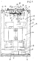
- Fig. 1 is a longitudinal section in the axis of the shaft of the electric motor.
- An electrohydraulic motor pump unit A has a closed housing G for an electric motor M running under oil and at least one hydraulic pump element P.
- the housing has a polygonal (rectangular or square) cross section or is round. It consists of a cover plate 1, a main housing part 2, which is formed as a casting with a cross plate 3 and a lower cover 4.
- the shaft of the electric motor M, designated 5 runs vertically and is rotatably mounted in the transverse wall 3 in a main bearing 6.
- An eccentric journal of the shaft 5 drives the one or more pump elements P, which is inserted between the lower cover 4 and the transverse wall 3, via a roller bearing 8.
- the upper end of the shaft 5 is centered with a central bearing pin 9 in a slide bearing 10 and is rotatably supported.
- the slide bearing 10 is held in a housing cover 11 of the cover plate 1, which is fixed oil-tight with fastening screws 12 at the front end of the main housing part 2 with the interposition of a seal 13.
- the housing cover 11 has an outer flat edge flange 33, from which a cup-shaped recess 14 extends into the interior of the housing G serving as an oil reservoir R.
- the depression 14 has a flat bottom, into which a sleeve-like socket 15 for the plain bearing 10 is molded.
- the recess 14 is covered at the top by a flat cover 16, which is screwed onto the edge flange 33 with retaining screws 17 and with the interposition of an elastic or insulating layer 18.
- the plate 16 has a central cable passage 19, in which a cable grommet 20 for guiding at least one outer cable 32 is expediently fixed.
- connection elements 23 lead from the electric motor M to connections 22, expediently to plug-in lugs, on connection elements 23 distributed in the bottom of the depression 14.
- Each connection element 23 is a cap screw with a long shaft 29, onto which a retaining nut 28 is screwed.
- the shaft 29 passes through insulation 25 in a bore in the bottom of the recess 14 and projects into a cavity 31 between the recess 14 and the cover 16.
- the connection 22, or the plug-in tab is secured by a washer 27, under which a Insulating body 24, advantageously an insulating washer, which is pressed against the underside of the housing cover 11.
- a sealing plate 26 made of insulating material which has through holes for the shafts 29 of the connecting elements 23 and covers the open end of the socket 15 and compresses a seal 30. Additional washers 27 are provided on the sealing plate under the retaining nuts 28.
- the outer cables 32 indicated by dashed lines in Fig. 1 are attached to the shafts 29 of the connecting elements 23 in the usual way, e.g. with connecting rings and additional clamping nuts.
- One of the connection elements 23 serves as a ground connection which, if necessary, is in conductive contact with the housing cover 11 without penetrating the bottom of the recess 14.
- the cover plate 1 can be prefabricated in the constellation shown in FIG. 1. After the rotor of the electric motor M with its shaft 5 through the main bearing 6 or already with this is pressed in, the cover plate 1 is placed and pressed with the slide bearing 10 on the journal 9 and fixed by means of the retaining screws 12.
- the pump elements P may have been installed together with the cover 4 beforehand or will be installed finally.
- the inner cables 21 are plugged into the plug-in tabs 22.
- the housing G is filled with oil via the electric motor M.
- the unit is then ready for operation. At the place of use, the cover 16 is removed and the outer cables 32 are inserted through the cable duct 19 and connected to the connection elements 23. Then only the cover 16 needs to be put on and fixed with the screws 17.
Abstract
Description
Die Erfindung betrifft ein elektrohydraulisches Motorpumpenaggregat der im Oberbegriff des Patentanspruchs 1 angegebenen Art.The invention relates to an electro-hydraulic motor pump unit of the type specified in the preamble of
Bei einem aus DE-C-24 13 691 bekannten Ölpumpenaggregat besteht das Gehäuse aus zwei topfförmigen Gußteilen. Der obere Gehäuseteil hält innen eine Fassung für das obere Ende der Welle des Elektromotors und eine öldichte Kabeldurchführung für einen von außen zum Elektromotor verlegten Kabelstrang. Der formentechnische Aufwand für die Herstellung des Gehäuseoberteils ist beträchtlich. Die Kabeldurchführung ist kritisch hinsichtlich Leckage. Der größte Nachteil ist jedoch, daß der Hersteller des Aggregats von vornherein nicht wissen kann, welche Länge des Kabelstranges für den Einsatzfall des Aggregats gebraucht wird. Ein zu langer Kabelstrang läßt sich zwar ablängen. Dies bedeutet jedoch einen unnötigen Verlust. Reicht die Kabelstranglänge nicht aus, ist es aufwendig, den Kabelstrang den Vorschriften entsprechend nachträglich zu verlängern. Ferner besteht permanent die Gefahr, daß Zug im Kabelstrang durch die Kabeldurchführung bis auf den Elektromotor übertragen wird. Für Wartungs- oder Reparaturarbeiten muß das Aggregat weitestgehend und mühsam zerlegt werden.In an oil pump unit known from DE-C-24 13 691, the housing consists of two pot-shaped castings. The upper housing part holds a socket for the upper end of the shaft of the electric motor and an oil-tight cable duct for a cable harness that is routed from the outside to the electric motor. The design effort for the production of the upper housing part is considerable. The cable entry is critical with regard to leakage. The main disadvantage, however, is that the manufacturer of the unit cannot know from the start what length of cable harness is needed for the application of the unit. A cable run that is too long can be cut to length. However, this means an unnecessary loss. If the cable loom is not long enough, it is time-consuming to subsequently extend the cable loom in accordance with the regulations. There is also a permanent risk that tension in the cable harness is transmitted through the cable duct to the electric motor. For maintenance or repair work, the unit must be dismantled as far as possible.
Bei einem aus DE-A-35 13 472 bekannten elektrohydraulischen Motorpumpenaggregat ist der Gehäusedeckel vom Gehäuse-Hauptteil trennbar und als Gußteil mit integrierter Fassung für das Lager der Elektromotorwelle ausgebildet. Der Kabelstrang zum Elektromotor wird durch eine öldichte Kabeldurchführung seitlich aus dem Gehäuse-Hauptteil verlegt. Dem Hersteller des Aggregats ist es nicht möglich, die jeweils richtige Kabelstranglänge vorzusehen.In an electrohydraulic motor pump unit known from DE-A-35 13 472, the housing cover can be separated from the main housing part and is designed as a cast part with an integrated socket for the bearing of the electric motor shaft. The cable harness to the electric motor is routed laterally out of the main housing section through an oil-tight cable entry. The manufacturer of the unit it is not possible to provide the correct cable length.
Bei eine aus DE-A-41 20 665 bekannten Hydraulikpumpe wird ein elektrischer Steuerteil mit einer unterseitig angebrachten Leiterplatte in einen zuvor in das Gehäuse eingepreßten Gehäuseteil eingesetzt. Gleichzeitig oder danach wird die elektrische Verbindung zum Motor hergestellt. Der Anschlußkabelstrang zum Motor wird durch den eingepreßten Gehäuseteil geführt und bedarf dort einer Abdichtung.In a hydraulic pump known from DE-A-41 20 665, an electrical control part with a printed circuit board attached on the underside is inserted into a housing part previously pressed into the housing. The electrical connection to the motor is established at the same time or afterwards. The connection cable harness to the motor is led through the pressed-in housing part and requires a seal there.
Eine aus US-A-3 001 006 bekannte Anschlußverbindung wird seitlich in eine Gehäusewand einer dynamoelektrischen Maschine eingesetzt. Die Anschlußkonstruktion steht in keiner baulichen Verbindung mit einer Gehäuseendplatte und einem Lagerschild für die durch das Gehäuse nach außen geführte Welle.A connector known from US-A-3 001 006 is inserted laterally into a housing wall of a dynamoelectric machine. The connecting structure is not structurally connected to a housing end plate and a bearing plate for the shaft which is guided through the housing to the outside.
Weiterer, zum technologischen Hintergrund zählender Stand der Technik ist enthalten in: US-A-4 362 351, US-A-1 792 044 und GB-A-1 281 107.Further prior art, which belongs to the technological background, is contained in: US-A-4 362 351, US-A-1 792 044 and GB-A-1 281 107.
Der Erfindung liegt die Aufgabe zugrunde, ein Aggregat der eingangs genannten Art zu schaffen, das herstellungstechnisch und montagetechnisch einfacher und kostengünstiger ist als die bekannten, und bei dem es unerheblich ist, welche Kabelstranglänge später für das Aggregat gebraucht wird.The invention has for its object to provide an assembly of the type mentioned, which is easier to manufacture and assemble technically and inexpensively than the known, and in which it is irrelevant which length of cable harness will be used later for the unit.
Die gestellte Aufgabe wird erfindungsgemäß mit den im Patentanspruch 1 enthaltenen Merkmalen gelöst.The object is achieved according to the invention with the features contained in
Bei dieser Ausbildung wird ein herstellungs- und montagetechnisch günstiger und preiswerter Gehäusedeckel vorgesehen, der zugleich auch Probleme aufgrund der bei der Herstellung noch unbekannten Länge des Anschlußkabelstranges beseitigt. Die im Gehäusedeckel fest und öldicht installierten Anschlußelemente ermöglichen nämlich die gleiche Länge für den im Inneren des Gehäuses zum Elektromotor führenden Kabelstrang. Die Länge des Außenkabels, über das die Anschlußelemente mit der Stromversorgung verbunden werden, braucht bei der Herstellung des Aggregats nicht berücksichtig zu werden. Der Benutzer kann das Aggregat wie einen herkömmlichen Elektromotor selbst anschließen. Dadurch werden bei der Herstellung des Aggregats für im späteren Einsatz unwichtige Kabellänge und die damit verbundenen Unkosten vermieden. Der Gehäusedeckel erfüllt eine Doppelfunktion, weil er als Lagerschild und für den Stromanschluß funktionell herangezogen wird. Der Gehäusedeckel ist eine einfach und kostengünstig vorfertigbare und leicht montierbare Einheit, läßt sich leicht abnehmen und gestattet einfachen Zugang bei Wartungs- und Reparaturarbeiten, ohne das Aggregat vollständig zerlegen zu müssen. Das Aggregat kann vor dem Versenden mit Öl gefüllt werden.This training is a manufacturing and assembly technology Inexpensive and inexpensive housing cover is provided, which at the same time also eliminates problems due to the length of the connecting harness, which is still unknown in the manufacture. The fixed and oil-tight connection elements installed in the housing cover enable the same length for the cable harness leading to the electric motor inside the housing. The length of the outer cable over which the connection elements are connected to the power supply need not be taken into account when manufacturing the unit. The user can connect the unit himself like a conventional electric motor. This avoids in the manufacture of the unit for cable lengths that are unimportant in later use and the associated costs. The housing cover fulfills a double function because it is used functionally as a bearing shield and for the power connection. The housing cover is a unit that is simple and inexpensive to manufacture and assemble, is easy to remove and allows easy access for maintenance and repair work without having to completely disassemble the unit. The unit can be filled with oil before shipping.
Die Ausführungsform gemäß Anspruch 2 ist bequem zu handhaben, entspricht den Schutzvorschriften und ermöglicht es dem späteren Benutzer oder Monteur des Aggregats, den elektrischen Anschluß so einfach wie möglich und frei zu gestalten, ohne den Hersteller des Aggregats von vornherein zu u.U. teuren Kompromissen zu zwingen. Der Hersteller des Aggregats spart Kabelmaterial und Kabellänge. Im abgedeckten Hohlraum sind die stromführenden Teile geborgen. Es ist genügend Platz, die Anschlüsse mit herkömmlichen Werkzeugen und Mitteln herzustellen. Ist die Kabellänge bekannt, dann kann der Hersteller einen entsprechenden Kabelstrang vormontieren, und ggfs. im Hohlraum speichern.The embodiment according to
Die Ausführungsform gemäß Anspruch 3 ist herstellungstechnisch und montagetechnisch günstig. Die Dichtplatte verhindert den Austritt von Öl im Lagerbereich. Die Anschlußelemente übernehmen eine Doppelfunktion, da sie die Dichtplatte lagesichern und die Antriebsenergie zum Elektromotor weiterleiten.The embodiment according to claim 3 is favorable in terms of production technology and assembly technology. The sealing plate prevents oil from escaping in the storage area. The connection elements have a double function, since they secure the sealing plate and transfer the drive energy to the electric motor.
Bei der Ausführungsform gemäß Anspruch 4 wird der Lagerbereich zuverlässig abgedichtet. Gleichzeitig isoliert die Dichtplatte.In the embodiment according to
Die Montage ist bei der Ausführungsform gemäß Anspruch 5 einfach. Ferner ist das Gehäuse gegenüber den Anschlußelementen elektrisch isoliert.The assembly is simple in the embodiment according to
Die Ausführungsform gemäß Anspruch 6 ist kostengünstig. Es lassen sich handelsübliche Schrauben gängiger Größe verwenden, die mit herkömmlichen Werkzeugen zu handhaben sind. Die elektrische Isolierung ist einfach. Am freien Schaftende lassen sich die Außenkabel in herkömmlicher Weise fest anschließen. Die Innenkabel brauchen nur an die Steckfahnen angesteckt zu werden, was die Montage und Demontage vereinfacht.The embodiment according to
Mit den Unterlegscheiben gemäß Anspruch 7 lassen sich die Anschlußelemente fest anziehen. Die Unterlegscheiben sind handelsüblich und preiswert.With the washers according to
Die O-Ringe gemäß Anspruch 8 sind handelsüblich in jeweils passenden Größen leicht erhältlich. Sie sorgen für die Öl-Abdichtung und für die elektrische Isolierung gegenüber dem Gehäuse.The O-rings according to
Der Gehäusedeckel gemäß Anspruch 9 ist kostengünstig und maßgenau als Blechformteil herstellbar. Er läßt sich mit allen Elementen vorfertigen und braucht nur mehr am Gehäuse angebracht zu werden. Das Wellenende wird sauber zentriert und präzise gelagert. Der Gehäusedeckel enthält aber auch die integrierte, öldichte und verlustarme Stromdurchführung. Die Scheibe deckt, den Vorschriften entsprechend, die stromführenden Teile nach außen ab.The housing cover according to
Gemäß Anspruch 10 verhindert der elastische Belag den Stromübertritt bei unkontrollierten Berührungen mit blanken Teilen. Mittels des elastischen Belags läßt sich der Deckel schwingungsarm und leicht lösbar festlegen.According to
Bei der Ausführungsform gemäß Anspruch 11 gestaltet sich das Anschließen der Außenkabel einfach. In der Durchstecktülle werden die Kabel gegen Beschädigungen geschützt. Außerdem wird der Zutritt von Verschmutzungen und Feuchtigkeit zu den Anschlußelementen behindert.In the embodiment according to
Eine kostengünstige Ausführungsform geht schließlich aus Anspruch 12 hervor. Der Gehäuse-Hauptteil läßt sich als Gußteil einfach und formgetreu herstellen. Die Querwand erhöht die Gestaltfestigkeit des Gehäuse-Hauptteils und sorgt für eine präzise Lagerung der Welle im Hauptlager. Der Gehäusedeckel ist im Stirnrand platzsparend und exakt zentriert.An inexpensive embodiment finally emerges from
Anhand der Zeichnung wird eine Ausführungsform des Erfindungsgegenstandes erläutert. Die Fig. 1 ist ein Längsschnitt in der Achse der Welle des Elektromotors.An embodiment of the subject matter of the invention is explained with the aid of the drawing. Fig. 1 is a longitudinal section in the axis of the shaft of the electric motor.
Ein elektrohydraulisches Motorpumpenaggregat A weist ein geschlossenes Gehäuse G für einen unter Öl laufenden Elektromotor M und wenigstens ein hydraulisches Pumpenelement P auf. Das Gehäuse hat mehreckigen (rechteckigen oder quadratischen) Querschnitt oder ist rund. Es besteht aus einer Deckplatte 1, einem als Gußteil mit einer Querplatte 3 einstückig ausgebildeten GehäuseHauptteil 2 und einem unteren Deckel 4. Die mit 5 bezeichnete Welle des Elektromotors M verläuft vertikal und ist in der Querwand 3 in einem Hauptlager 6 drehbar gelagert. Ein exzentrischer Achszapfen der Welle 5 treibt über ein Wälzlager 8 das eine oder mehrere Pumpenelemente P, das zwischen dem unteren Deckel 4 und der Querwand 3 eingesetzt ist.An electrohydraulic motor pump unit A has a closed housing G for an electric motor M running under oil and at least one hydraulic pump element P. The housing has a polygonal (rectangular or square) cross section or is round. It consists of a
Das obere Ende der Welle 5 ist mit einem zentrischen Lagerzapfen 9 in einem Gleitlager 10 zentriert und drehgelagert. Das Gleitlager 10 ist in einem Gehäusedeckel 11 der Deckplatte 1 gehaltert, die mit Befestigungsschrauben 12 am Stirnende des Gehäuse-Haupt- teils 2 unter Zwischenlage einer Dichtung 13 öldicht festgelegt ist. Der Gehäusedeckel 11 besitzt einen äußeren ebenen Randflansch 33, von dem sich eine topfförmige Vertiefung 14 ins Innere des als Ölreservoir R dienenden Gehäuses G erstreckt. Die Vertiefung 14 hat einen ebenen Boden, in den eine hülsenartige Fassung 15 für das Gleitlager 10 eingeformt ist. Die Vertiefung 14 wird oben durch einen ebenen Deckel 16 abgedeckt, der mit Halteschrauben 17 und unter Zwischenlage einer elastischen bzw. isolierenden Schicht 18 auf den Randflansch 33 geschraubt ist. Die Platte 16 weist einen mittigen Kabeldurchgang 19 auf, in dem zweckmäßigerweise eine Kabeltülle 20 zum Durchführen wenigstens eines Außenkabels 32 festgelegt ist.The upper end of the
Vom Elektromotor M führen Innenkabel 21 zu Anschlüssen 22, zweckmäßigerweise zu Steckfahnen, an im Boden der Vertiefung 14 verteilten Anschlußelementen 23. Jedes Anschlußelement 23 ist eine Kopfschraube mit einem langen Schaft 29, auf den eine Haltemutter 28 aufgeschraubt ist. Der Schaft 29 durchsetzt eine Isolierung 25 in einer Bohrung des Bodens der Vertiefung 14 und ragt in einen Hohlraum 31 zwischen der Vertiefung 14 und dem Deckel 16. Der Anschluß 22, bzw. die Steckfahne, wird durch eine Unterlegscheibe 27 gesichert, unter der sich ein Isolierkörper 24, zweckmäßigerweise eine Isolierscheibe, befindet, die an die Unterseite des Gehäusedeckels 11 angepreßt ist. In der Vertiefung 14 ist eine Dichtplatte 26 aus isolierendem Material vorgesehen, die Durchgangsbohrungen für die Schäfte 29 der Anschlußelemente 23 aufweist und das offene Ende der Fassung 15 überdeckt und eine Dichtung 30 komprimiert. Unter den Haltemuttern 28 sind sind auf der Dichtplatte weitere Unterlegscheiben 27 vorgesehen. Die in Fig. 1 strichliert angedeuteten Außenkabel 32 werden an den Schäften 29 der Anschlußelemente 23 auf übliche Weise, z.B. mit Anschlußringen und weiteren Spannmuttern, festgelegt. Eines der Anschlußelemente 23 dient als Masseanschluß, der gegebenenfalls, ohne den Boden der Vertiefung 14 zu durchsetzen, mit dem Gehäusedeckel 11 in leitendem Kontakt steht.
Bei der Montage des Aggregats A werden das Hauptlager 6 in die Querwand 3 und der Stator des Elektromotors M in den Gehäuse-Hauptteil 2 eingepreßt. Die Deckplatte 1 kann in der in Fig. 1 gezeigten Konstellation vorgefertigt sein. Nachdem der Rotor des Elektromotors M mit seiner Welle 5 durch das Hauptlager 6 oder bereits mit diesem eingepreßt ist, wird die Deckplatte 1 aufgesetzt und mit dem Gleitlager 10 auf den Lagerzapfen 9 aufgepreßt und mittels der Halteschrauben 12 festgelegt. Die Pumpenelemente P sind gegebenenfalls schon vorher zusammen mit dem Deckel 4 eingebaut bzw. werden abschließend eingebaut. Vor dem Aufpressen der Deckplatte 1 werden die Innenkabel 21 an die Steckfahnen 22 angesteckt. Danach wird das Gehäuse G bis über den Elektromotor M mit Öl befüllt. Das Aggregat ist dann betriebsfertig. Am Einsatzort wird der Deckel 16 abgenommen und werden die Außenkabel 32 durch die Kabeldurchführung 19 eingeführt und an die Anschlußelemente 23 angeschlossen. Danach braucht nur mehr der Deckel 16 aufgesetzt und mit den Schrauben 17 festgelegt zu werden.When assembling the unit A, the
Claims (12)
Applications Claiming Priority (2)
| Application Number | Priority Date | Filing Date | Title |
|---|---|---|---|
| DE9405873U DE9405873U1 (en) | 1994-04-08 | 1994-04-08 | Electro-hydraulic motor pump unit |
| DE9405873U | 1994-04-08 |
Publications (2)
| Publication Number | Publication Date |
|---|---|
| EP0676851A1 true EP0676851A1 (en) | 1995-10-11 |
| EP0676851B1 EP0676851B1 (en) | 1999-07-07 |
Family
ID=6907089
Family Applications (1)
| Application Number | Title | Priority Date | Filing Date |
|---|---|---|---|
| EP95105304A Expired - Lifetime EP0676851B1 (en) | 1994-04-08 | 1995-04-07 | Electrohydraulic motor-pump unit |
Country Status (4)
| Country | Link |
|---|---|
| EP (1) | EP0676851B1 (en) |
| AT (1) | ATE182039T1 (en) |
| DE (1) | DE9405873U1 (en) |
| DK (1) | DK0676851T3 (en) |
Citations (7)
| Publication number | Priority date | Publication date | Assignee | Title |
|---|---|---|---|---|
| US1792044A (en) * | 1929-06-19 | 1931-02-10 | Apex Electrical Mfg Co | Terminal block |
| US3001006A (en) * | 1958-10-27 | 1961-09-19 | Gen Motors Corp | Terminal connection |
| GB1281107A (en) * | 1970-07-02 | 1972-07-12 | Nippon Denso Co | Improvements in starter motors for internal combustion engines |
| DE2413691A1 (en) * | 1974-03-21 | 1975-10-02 | Heilmeier & Weinlein | PRESSURE OIL PUMP |
| US4362351A (en) * | 1981-02-06 | 1982-12-07 | Towmotor Corporation | Terminal assembly |
| DE3513472A1 (en) * | 1985-04-15 | 1986-10-16 | Heilmeier & Weinlein Fabrik für Oel-Hydraulik GmbH & Co KG, 8000 München | HYDRAULIC ENGINE PUMP UNIT |
| DE4120665A1 (en) * | 1991-06-22 | 1992-12-24 | Teves Gmbh Alfred | ELECTRICALLY DRIVEN HYDRAULIC PUMP |
-
1994
- 1994-04-08 DE DE9405873U patent/DE9405873U1/en not_active Expired - Lifetime
-
1995
- 1995-04-07 DK DK95105304T patent/DK0676851T3/en active
- 1995-04-07 EP EP95105304A patent/EP0676851B1/en not_active Expired - Lifetime
- 1995-04-07 AT AT95105304T patent/ATE182039T1/en not_active IP Right Cessation
Patent Citations (7)
| Publication number | Priority date | Publication date | Assignee | Title |
|---|---|---|---|---|
| US1792044A (en) * | 1929-06-19 | 1931-02-10 | Apex Electrical Mfg Co | Terminal block |
| US3001006A (en) * | 1958-10-27 | 1961-09-19 | Gen Motors Corp | Terminal connection |
| GB1281107A (en) * | 1970-07-02 | 1972-07-12 | Nippon Denso Co | Improvements in starter motors for internal combustion engines |
| DE2413691A1 (en) * | 1974-03-21 | 1975-10-02 | Heilmeier & Weinlein | PRESSURE OIL PUMP |
| US4362351A (en) * | 1981-02-06 | 1982-12-07 | Towmotor Corporation | Terminal assembly |
| DE3513472A1 (en) * | 1985-04-15 | 1986-10-16 | Heilmeier & Weinlein Fabrik für Oel-Hydraulik GmbH & Co KG, 8000 München | HYDRAULIC ENGINE PUMP UNIT |
| DE4120665A1 (en) * | 1991-06-22 | 1992-12-24 | Teves Gmbh Alfred | ELECTRICALLY DRIVEN HYDRAULIC PUMP |
Also Published As
| Publication number | Publication date |
|---|---|
| ATE182039T1 (en) | 1999-07-15 |
| DE9405873U1 (en) | 1994-06-30 |
| EP0676851B1 (en) | 1999-07-07 |
| DK0676851T3 (en) | 1999-12-06 |
Similar Documents
| Publication | Publication Date | Title |
|---|---|---|
| DE3105428C2 (en) | Wet-running motor for a pump | |
| DE10238318B4 (en) | Electric power steering device | |
| EP1827934B1 (en) | Electrohydraulic pressure control device for automotive brake systems | |
| EP2500575B1 (en) | Heat circulation pump | |
| EP2453558B1 (en) | Pump unit | |
| EP1821390B1 (en) | Electric motor for an adjustable stabiliser | |
| EP2500574B1 (en) | Heat circulation pump | |
| DE102009008348A1 (en) | Motor for an electric power steering device with integrated control unit and electric power steering device | |
| EP1171680B1 (en) | Motor housing and pole-well, in particular for electric window or sunroof motors | |
| EP1384307A1 (en) | Electronically commutated direct current motor | |
| EP0471876A1 (en) | Motor-gear-drive unit, especially motor vehicle window lifter drive | |
| DE10130117A1 (en) | Housing cover for an electric motor, in particular for an electronically commutated direct current motor | |
| DE102015216693A1 (en) | Electrical connector assembly, electronic control unit using the same, and electric power steering system with it | |
| EP0357913A2 (en) | Motor with a wet rotor | |
| DE10005505B4 (en) | heat pump | |
| DE4027176C3 (en) | Motor operated pump | |
| EP1351846B1 (en) | Motor pump unit, particularly a motor vehicle braking device | |
| DE102004030721B3 (en) | Canned electric motor for a central heating water circulation pump has a metal housing | |
| WO2000051863A1 (en) | Motor-drive assembly, especially a motor-pump assembly for an anti-blocking brake device of an automobile | |
| DE102019109693B4 (en) | Drive unit with an electric machine and with a control unit | |
| EP0975501B1 (en) | Hydraulic unit for a hydraulic control device and/or regulating device | |
| EP3369933A1 (en) | Circulation pump for heating system | |
| EP0676851B1 (en) | Electrohydraulic motor-pump unit | |
| EP1921733B1 (en) | AC motor and controller | |
| DE19518215A1 (en) | Hydro-pump motor |
Legal Events
| Date | Code | Title | Description |
|---|---|---|---|
| PUAI | Public reference made under article 153(3) epc to a published international application that has entered the european phase |
Free format text: ORIGINAL CODE: 0009012 |
|
| AK | Designated contracting states |
Kind code of ref document: A1 Designated state(s): AT BE CH DE DK FR GB IT LI LU NL SE |
|
| 17P | Request for examination filed |
Effective date: 19960410 |
|
| RBV | Designated contracting states (corrected) |
Designated state(s): AT BE CH DE DK FR GB IT LI LU NL SE |
|
| GRAG | Despatch of communication of intention to grant |
Free format text: ORIGINAL CODE: EPIDOS AGRA |
|
| 17Q | First examination report despatched |
Effective date: 19980710 |
|
| GRAG | Despatch of communication of intention to grant |
Free format text: ORIGINAL CODE: EPIDOS AGRA |
|
| GRAH | Despatch of communication of intention to grant a patent |
Free format text: ORIGINAL CODE: EPIDOS IGRA |
|
| GRAH | Despatch of communication of intention to grant a patent |
Free format text: ORIGINAL CODE: EPIDOS IGRA |
|
| GRAA | (expected) grant |
Free format text: ORIGINAL CODE: 0009210 |
|
| AK | Designated contracting states |
Kind code of ref document: B1 Designated state(s): AT BE CH DE DK FR GB IT LI LU NL SE |
|
| REF | Corresponds to: |
Ref document number: 182039 Country of ref document: AT Date of ref document: 19990715 Kind code of ref document: T |
|
| REG | Reference to a national code |
Ref country code: CH Ref legal event code: NV Representative=s name: PATENTANWALTSBUERO JEAN HUNZIKER Ref country code: CH Ref legal event code: EP |
|
| GBT | Gb: translation of ep patent filed (gb section 77(6)(a)/1977) |
Effective date: 19990708 |
|
| REF | Corresponds to: |
Ref document number: 59506327 Country of ref document: DE Date of ref document: 19990812 |
|
| ITF | It: translation for a ep patent filed |
Owner name: SOCIETA' ITALIANA BREVETTI S.P.A. |
|
| ET | Fr: translation filed | ||
| REG | Reference to a national code |
Ref country code: DK Ref legal event code: T3 |
|
| PG25 | Lapsed in a contracting state [announced via postgrant information from national office to epo] |
Ref country code: LU Free format text: LAPSE BECAUSE OF NON-PAYMENT OF DUE FEES Effective date: 20000407 |
|
| PGFP | Annual fee paid to national office [announced via postgrant information from national office to epo] |
Ref country code: DK Payment date: 20000426 Year of fee payment: 6 |
|
| PG25 | Lapsed in a contracting state [announced via postgrant information from national office to epo] |
Ref country code: BE Free format text: LAPSE BECAUSE OF NON-PAYMENT OF DUE FEES Effective date: 20000430 |
|
| PLBE | No opposition filed within time limit |
Free format text: ORIGINAL CODE: 0009261 |
|
| STAA | Information on the status of an ep patent application or granted ep patent |
Free format text: STATUS: NO OPPOSITION FILED WITHIN TIME LIMIT |
|
| 26N | No opposition filed | ||
| BERE | Be: lapsed |
Owner name: HEILMEIER & WEINLEIN FABRIK FUR OEL-HYDRAULIK G.M Effective date: 20000430 |
|
| PG25 | Lapsed in a contracting state [announced via postgrant information from national office to epo] |
Ref country code: DK Free format text: LAPSE BECAUSE OF NON-PAYMENT OF DUE FEES Effective date: 20010407 |
|
| PGFP | Annual fee paid to national office [announced via postgrant information from national office to epo] |
Ref country code: SE Payment date: 20010413 Year of fee payment: 7 |
|
| PGFP | Annual fee paid to national office [announced via postgrant information from national office to epo] |
Ref country code: NL Payment date: 20010424 Year of fee payment: 7 |
|
| PGFP | Annual fee paid to national office [announced via postgrant information from national office to epo] |
Ref country code: GB Payment date: 20010430 Year of fee payment: 7 |
|
| REG | Reference to a national code |
Ref country code: DK Ref legal event code: EBP |
|
| REG | Reference to a national code |
Ref country code: GB Ref legal event code: IF02 |
|
| PG25 | Lapsed in a contracting state [announced via postgrant information from national office to epo] |
Ref country code: GB Free format text: LAPSE BECAUSE OF NON-PAYMENT OF DUE FEES Effective date: 20020407 |
|
| PG25 | Lapsed in a contracting state [announced via postgrant information from national office to epo] |
Ref country code: SE Free format text: LAPSE BECAUSE OF NON-PAYMENT OF DUE FEES Effective date: 20020408 |
|
| PGFP | Annual fee paid to national office [announced via postgrant information from national office to epo] |
Ref country code: FR Payment date: 20020423 Year of fee payment: 8 |
|
| PGFP | Annual fee paid to national office [announced via postgrant information from national office to epo] |
Ref country code: AT Payment date: 20020425 Year of fee payment: 8 |
|
| PGFP | Annual fee paid to national office [announced via postgrant information from national office to epo] |
Ref country code: CH Payment date: 20020430 Year of fee payment: 8 |
|
| PG25 | Lapsed in a contracting state [announced via postgrant information from national office to epo] |
Ref country code: NL Free format text: LAPSE BECAUSE OF NON-PAYMENT OF DUE FEES Effective date: 20021101 |
|
| EUG | Se: european patent has lapsed |
Ref document number: 95105304.0 |
|
| GBPC | Gb: european patent ceased through non-payment of renewal fee |
Effective date: 20020407 |
|
| NLV4 | Nl: lapsed or anulled due to non-payment of the annual fee |
Effective date: 20021101 |
|
| PG25 | Lapsed in a contracting state [announced via postgrant information from national office to epo] |
Ref country code: AT Free format text: LAPSE BECAUSE OF NON-PAYMENT OF DUE FEES Effective date: 20030407 |
|
| PG25 | Lapsed in a contracting state [announced via postgrant information from national office to epo] |
Ref country code: LI Free format text: LAPSE BECAUSE OF NON-PAYMENT OF DUE FEES Effective date: 20030430 Ref country code: CH Free format text: LAPSE BECAUSE OF NON-PAYMENT OF DUE FEES Effective date: 20030430 |
|
| REG | Reference to a national code |
Ref country code: CH Ref legal event code: PL |
|
| PG25 | Lapsed in a contracting state [announced via postgrant information from national office to epo] |
Ref country code: FR Free format text: LAPSE BECAUSE OF NON-PAYMENT OF DUE FEES Effective date: 20031231 |
|
| REG | Reference to a national code |
Ref country code: FR Ref legal event code: ST |
|
| PG25 | Lapsed in a contracting state [announced via postgrant information from national office to epo] |
Ref country code: IT Free format text: LAPSE BECAUSE OF NON-PAYMENT OF DUE FEES;WARNING: LAPSES OF ITALIAN PATENTS WITH EFFECTIVE DATE BEFORE 2007 MAY HAVE OCCURRED AT ANY TIME BEFORE 2007. THE CORRECT EFFECTIVE DATE MAY BE DIFFERENT FROM THE ONE RECORDED. Effective date: 20050407 |
|
| PGFP | Annual fee paid to national office [announced via postgrant information from national office to epo] |
Ref country code: DE Payment date: 20110527 Year of fee payment: 17 |
|
| REG | Reference to a national code |
Ref country code: DE Ref legal event code: R119 Ref document number: 59506327 Country of ref document: DE Effective date: 20121101 |
|
| PG25 | Lapsed in a contracting state [announced via postgrant information from national office to epo] |
Ref country code: DE Free format text: LAPSE BECAUSE OF NON-PAYMENT OF DUE FEES Effective date: 20121101 |