EP0675974B1 - Elektrolysezelle für die herstellung von metallen - Google Patents
Elektrolysezelle für die herstellung von metallen Download PDFInfo
- Publication number
- EP0675974B1 EP0675974B1 EP94903688A EP94903688A EP0675974B1 EP 0675974 B1 EP0675974 B1 EP 0675974B1 EP 94903688 A EP94903688 A EP 94903688A EP 94903688 A EP94903688 A EP 94903688A EP 0675974 B1 EP0675974 B1 EP 0675974B1
- Authority
- EP
- European Patent Office
- Prior art keywords
- particles
- slurry
- cell
- cathode
- liquid metal
- Prior art date
- Legal status (The legal status is an assumption and is not a legal conclusion. Google has not performed a legal analysis and makes no representation as to the accuracy of the status listed.)
- Expired - Lifetime
Links
Images


Classifications
-
- C—CHEMISTRY; METALLURGY
- C25—ELECTROLYTIC OR ELECTROPHORETIC PROCESSES; APPARATUS THEREFOR
- C25C—PROCESSES FOR THE ELECTROLYTIC PRODUCTION, RECOVERY OR REFINING OF METALS; APPARATUS THEREFOR
- C25C3/00—Electrolytic production, recovery or refining of metals by electrolysis of melts
- C25C3/06—Electrolytic production, recovery or refining of metals by electrolysis of melts of aluminium
- C25C3/08—Cell construction, e.g. bottoms, walls, cathodes
-
- C—CHEMISTRY; METALLURGY
- C25—ELECTROLYTIC OR ELECTROPHORETIC PROCESSES; APPARATUS THEREFOR
- C25C—PROCESSES FOR THE ELECTROLYTIC PRODUCTION, RECOVERY OR REFINING OF METALS; APPARATUS THEREFOR
- C25C3/00—Electrolytic production, recovery or refining of metals by electrolysis of melts
- C25C3/06—Electrolytic production, recovery or refining of metals by electrolysis of melts of aluminium
Definitions
- the present invention relates to electrolytic cells for use in the production of metals by electrolysis and to cathodes for use therein.
- the invention is particularly suitable for use in the production of aluminium.
- Aluminium is generally produced by the electrolysis of alumina.
- Alumina is dissolved in a bath of molten cryolite at a temperature in the range of 950 - 1000°C.
- Carbonaceous electrodes are frequently used for both the cathode and the anode.
- the anode is placed uppermost in the electrolytic cell and the cathode structure generally forms the bottom floor of the cell.
- the molten bath of cryolite and dissolved alumina sits between the cathode and the anode. Liquid aluminium metal is electrodeposited at the cathode.
- the cryolite bath is a very aggressive medium and will readily attack the electrode material at the cell operating temperature. This does not form a major problem with regards to the anodes as the anodes are consumed in the electrolytic reaction and require replacement every few weeks. As the anodes form the upper element of the cell, anode replacement is a relatively simple operation that does not cause great disruption to cell operation.
- the cathode forms the lower part of the cell and indeed in most aluminium reduction pots, the bottom of the pot consists of a refractory layer having the carbonaceous cathodes being formed as a layer on top.
- Cathode replacement requires shut-down of the cell and removal of the lining. This procedure is obviously time consuming and represents down-time for the cell. Consequently, aluminium reduction cells are operated under conditions such that cathode life is in the order of 2 to 5 years.
- aluminium reduction cells are generally operated under conditions such that exposure of the cathode to bath materials is substantially avoided. This is obtained in conventional cells by maintaining a pool of molten aluminium above the cathode. Molten aluminium does not attack the cathode to the same extent as the bath materials and hence protects the cathode from the bath. Although providing satisfactory cathode life, maintaining a pool of molten aluminium in the cell requires a number of compromises in cell operation, including the requirement that anode-cathode distance be greater than optimal. Aluminium reduction cells utilise large electric currents which, in turn, can create large electromagnetic fluxes.
- the electromagnetic fluxes contribute to the formation of wave motion within the pool of molten aluminium, making prediction of the exact depth of the aluminium pool, and therefore the minimum spacing between the anode and the interface between aluminium and cryolite somewhat imprecise. Therefore, in order to prevent the pool of molten aluminium contacting the anode and causing a short circuit in the cell, the anodes are positioned in the cell at a position substantially above the normal or expected position of the aluminium/cryolite interface. This reduces the efficiency of the cell.
- a safety margin must be incorporated into the anode - cathode distance in order to account for localised disruptions in the aluminium pool.
- the packing is frequently produced from expensive materials in order to impart resistance to the corrosive effects of the bath materials.
- An alternative cell construction which does away with the pool of molten aluminium above the cathode is the drained cathode cell.
- the bulk of the aluminium metal is continuously drained from the cathode as it is formed, leaving only a thin film of molten aluminium on the surface of the cathode.
- Drained cathode cells permit close anode - cathode spacing which can result in greatly enhanced cell efficiency.
- Formation of a stable film of aluminium on the cathode requires that the cathode be made from a metal-wettable material. Furthermore, as only a thin film of aluminium protects the cathode from the bath material, the risk of bath material coming into contact with the cathode is increased.
- the cathode must be made from bath resistant material, such as borides, nitrides and carbides of refractory hard metals. Preferred materials are both electrically conductive and aluminium wettable. Studies on drained cathode cells have generally found that very pure materials must be used for the cathodes in order to obtain sufficient resistance to the bath materials.
- Past efforts to develop an energy efficient aluminium reduction cell have required the use of bath resistant materials either as the cathode or in close proximity to the cathode.
- ceramics made from refractory hard materials have been proposed. Such ceramics have generally been formed by sintering very fine particles to produce shaped artefacts (e.g. rods, cylinders, pipes, tiles) by hot, cold or reaction sintering.
- the sintered shapes can be used as a loose fill in a packed bed cell or somehow attached to the carbonaceous substrate (e.g. by gluing, reaction bonding, physical anchoring).
- Sintered ceramics have been found to suffer detachment from carbon substrates, mechanical breakage during normal cell servicing operations such as tapping and anode setting and become infiltrated by aluminium metal and disrupted at grain boundaries. Once intergranular attack on the sintered ceramic has occurred, the very fine powders used to produce the ceramic become dislodged from the structure and entrained in the metal, thus being lost from the surface.
- cermets containing refractory hard materials have utilised cermets containing refractory hard materials, refractory hard material coatings produced by processes such as electrodeposition, chemical vapour deposition and plasma spraying, and refractory hard material composites. All of the above approaches aim to produce a coherent structure containing a refractory hard material, which coherent structure is preferably resistant to infiltration by molten metal.
- the upper layer is preferably made from sintered tabular alumina or fused alumina aggregate.
- the shapes are preferably spheres of diameter 5-30 mm.
- the patent states that the important requirement of the shapes is that they can pack to produce a rigid skeleton and a high bulk density. Two factors determine the size of the shapes. If the shapes are too large, then large voids may be left between them by shrinkage or movement of intervening material. If the shapes are too small, they may be easily mechanically displaced by the motion of the cell liquids or mechanical prodding.
- the patent further states that it has been found that an alumina lining containing a skeletal structure of 20 mm diameter alumina spheres is hard and dimensionally stable.
- EP-A-0 145411 and EP-A-0 145412 relate to cathode current collectors embedded in the potlining of an aluminium reduction cell.
- the cathode current collector includes a section that has a major proportion of discrete bodies of a material that is electrically conductive and wettable by molten aluminium. The bodies are joined or surrounded by a minor proportion of an aluminium-containing metal. This section of the cathode current collector is positioned in the cell such that the metal is at least partly fluid when the cell is in operation.
- the metal wettable bodies of the upper section of the cathode current collector are preferably present in a close packed array.
- the bodies are preferably of a regular shape and are large enough not to be readily shifted by magnetic stirring of the molten metal.
- the cathode current collectors described in these European patent applications are embedded and completely surrounded by the potlining of the cell. Therefore, the potlining acts to stabilise the bodies that form the upper section of the cathode current collector.
- a depression is formed in the potlining directly above the collector. The depression may be filled with relatively large balls of titanium diboride to stabilise the metal in the depression.
- GB-A-2065174 describes a cathode for an aluminium smelting furnace.
- the cathode is of the liquid metal type, and comprises an uppermost freely moveable layer of molten metal at least 2 mm thick resting on, and penetrating into a bed of particulate material which rests on the floor of the furnace, and which is insert and solid at the operating temperatures of the furnace.
- the bed of particulate material suppresses or retards movement of the liquid metal, thereby enabling the anode-to-cathode distance in the cell to be reduced.
- the particle size of the particulate bed material is between 0.1 and 100 mm, and in any case is less than half the thickness of the bed.
- EP-A-0094353 describes an aluminium smelting cell having a cathode comprising a packed bed of alumina pieces with interstices through the packed bed, whereby aluminum can fill gaps in the packing to maintain uniform electrical conductivity through the packed bed liquid metal cathode.
- Typical packing materials are 2.5 cm alumina cubes.
- EP-A-0115688 describes reaction sintered cermet bodies and the use therefore in aluminium smelting cells, for example as cathode materials.
- US-A-4511449 describes an aluminium smelting cell having a liquid aluminium cathode.
- the cathode is provided with a bed of pieces of composite material bonded together which sink in molten aluminium.
- the present invention provides an electrolytic reduction cell for the production of metal in which liquid metal is deposited at or adjacent an upper surface of a cathode, said electrolytic reduction cell including an anode structure and a cathode located beneath the anode structure wherein an upper portion of the cathode comprises an aggregate of particles that are substantially unreactive with the liquid metal, the particles being sized and shaped such that in operation of the cell and a slurry of liquid metal and particles is established in at least an upper part of the aggregate, wherein said slurry is a substantially uniform dispersion of said particles in a continuous liquid phase of said liquid metal, and said slurry has a viscosity at least an order of magnitude larger than the viscosity of the liquid metal, whereby under operation conditions of the cell the slurry is relatively immobile.
- the present invention further provides a method for the production of a metal by electrolysis in an electrolytic cell comprising an upper anode, a lower cathode and an electrolysis bath therebetween in which liquid metal is deposited at or adjacent an upper surface of the cathode wherein an upper portion of the cathode comprises an aggregate of particles that are substantially unreactive with the liquid metal, said method characterised in that a slurry of liquid metal and particles is established in that in at least an upper part of the aggregate, wherein said slurry is a substantially uniform dispersion of said particles in a continuous liquid phase of said liquid metal, said slurry having a viscosity at least an order of magnitude larger than the viscosity of the liquid metal, whereby under the operating conditions of the cell the slurry is relatively immobile.
- said particles have a specific gravity greater than the specific gravity of the metal, said particles being sized in the range of 0.1 ⁇ m to 1 mm or more.
- slurry is taken to mean a substantially uniform dispersion of particles in a continuous liquid phase of liquid metal.
- liquid metal is able to penetrate or otherwise be present at least part way into the aggregate of particles to form a slurry of liquid metal and particles.
- the particle size distribution and shape of the particles in the aggregate of particles can be arranged to ensure that the thus formed slurry has a viscosity sufficiently high such that the slurry moves sluggishly, if at all, during operation of the electrolytic cell and therefore remains relatively immobile on the cathode surface.
- loss of the particles from the cathode during use occurs at only a slow rate, if at all. This rate of loss of particles can be sufficiently low to ensure that the cathode does not prematurely wear during use. Therefore, the protective effect of the particles may be maintained for the design life of the cathode.
- the particles of the aggregate of particles are preferably produced from a material that is wetted by the liquid metal.
- particles of a non-wetted material may also be used. If the particles of non-wetted material are used, the maximum size of the particles is governed by the wetting angle and the requirement that the liquid phase be the continuous phase of the slurry. The maximum particle size for a material that is not wetted by the liquid metal can be determined using surface chemistry theory.
- the particles be made from a material that is electrically conductive, although this is not an absolute requirement of the present invention. If non-electrically conductive particles are used, the content of liquid metal in the slurry that forms on the upper part of the cathode will ensure that flow of electrical current in the cell is maintained. If non-electrically conductive particles are used, the slurry should rest on an electrically conductive substrate or the cathode current collectors should be in contact with at least the lower part of the slurry.
- the slurry of liquid metal and particles exhibits plastic flow properties with a yield stress of at least 10N/m 2 .
- Fluids that exhibit plastic flow properties will not flow until a critical yield stress is applied to the fluid. Until the yield stress is exceeded, plastic fluids act as solids.
- Such fluids are also referred to as viscoplastic and in this regard reference is made to J.M. Coulson and J.F. Richardson, "Chemical Engineering, Volume 1,” published by Pergamon Press, 1977, page 38.
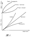
- Figure 1 also shows the relationship between shear stress and shear rate for different flow behaviours, and the yield stress for plastic fluids is clearly shown in this Figure.
- the yield stress of a plastic fluid may be defined as the minimum stress required to produce a shearing flow. At shear stresses below the yield value, the material behaves as a solid. Once the yield value is exceeded, the fluid may display Newtonian, pseudoplastic or dilatant flow behaviour.
- the cathode of the electrolytic reduction cell comprises a substrate having a coating on its upper surface, said coating comprising an aggregate of particles.
- liquid metal penetrates or is otherwise present at least part way into the aggregate to form the slurry of liquid metal and particles.
- the cell of the present invention differs substantially from prior art electrolytic reduction cells.
- the upper portion of the cathode of the cell was generally designed to prevent infiltration of liquid metal into the metal wettable material. Any infiltration of liquid metal usually resulted in progressive failure of the material.
- the upper part of the cathode of the electrolytic reduction cell of the present invention has been designed such that it is at least partly penetrated by liquid metal to form a relatively immobile slurry layer and this relatively immobile slurry protects the cathode from further attack by the bath materials.
- the present invention is particularly suited to the production of aluminium metal and for convenience, the invention will hereafter be described with respect to the production of aluminium. However, it will be appreciated that the invention can be used in the production of any metal by an electrolytic process in which liquid metal is deposited at or adjacent the cathode.
- the particles are preferably produced from a substance that is wettable by the liquid metal, although non-wetted substances may also be used.
- the metal-wettable substance is preferably a boride, carbide or nitride of a refractory hard metal (RHM).
- the refractory hard metal (RHM) may be selected from titanium, tantalum, niobium or zirconium.
- the preferred metal-wettable substance is titanium diboride. A mixture of different refractory hard metals may be used.
- non-wetted substances may also be used, including silicon carbide, alumina and particles sold by Comalco Aluminium Limited under the trade mark MICRAL (these particles are predominantly of a calcined bauxite material).
- the major requirements of the particles used in the aggregate are that they should be substantially unreactive with the molten metal (and preferably also the electrolytic bath) and they must be capable of being dispersed in molten aluminium to form a slurry.
- the cathode used in the electrolytic reduction cell of the present invention preferably comprises a substrate having a coating that includes a refractory hard metal boride, carbide or nitride.
- the substrate may be a carbonaceous material.
- the cathode may be formed entirely from a material that includes a refractory hard metal boride, carbide or nitride, the relatively high expense of such borides, carbides or nitrides means that the use of a coating of such materials on a substrate is preferred in order to minimise the quantity of such materials required.
- the substrate is preferably a non-smooth, preferably carbonaceous, substance suitable for use in aluminium electrolysis, such as anthracite, graphitised pitch or graphitised petroleum coke, metallurgical coke or titanium diboride - carbon composite.
- the surface of the substrate preferably has a degree of surface roughness to help prevent film slippage. Furthermore, the reaction between aluminium, bath and carbon leads to the formation of aluminium carbide at the interface between the slurry layer and the substrate. This aluminium carbide layer may provide mechanical keying between the substrate and the particles in the slurry layer.
- the upper portion of or coating on the cathode is preferably formed from a graded aggregate of particles of borides, carbides or nitrides of a refractory hard metal.
- the particles of refractory hard metal borides, carbides or nitrides are preferably irregularly shaped and have particle sizes ranging from sub-micron up to 1 mm or more and more preferably between 5 and 500 microns.
- the aggregate preferably comprises particles or mixtures of particles, which have a higher specific gravity than aluminium and are wetted by aluminium.
- the particles are preferably single crystals. If multi-grain particles are used, it is possible that they will break down during use of the cell. The upper size limit of particles is therefore somewhat restricted by the availability and cost of large single crystals.
- the solid particles are preferably electrically conductive.
- a range of particle sizes, shapes and mixtures thereof can be used, for example, hexagonal plates, elongated platelets, spindle shaped needles, cubic crystals, spherical particles or irregular shaped fractured crystals.
- the preferred combinations of particle shape, size and volume content of particles are set to give slurry with a suitable rheology to remain immobile during cell operation and resistance to dislodgement of individual particles from the upper surface of the slurry.
- One especially preferred embodiment comprises a mixture of particles having hexagonal platelet shapes and diameter 30-70 microns, irregular fracture particles in the range 150-350 microns and spindle particles having a maximum diameter of 30-50 microns and length of 150-350 microns.
- the particles preferably have a specific gravity of at least 2.5 g/cm 3 , with particles having a specific gravity in the range of 4-6 g/cm 3 being more preferred.
- the layer of slurry on the upper part of the cathode during operation of the reduction cell may be formed in a number of different ways.
- One method includes manufacturing the cathode externally to the cell such that an upper part of the cathode comprises a bound aggregate of particles.
- This bound aggregate of particles is designed such that liquid metal can penetrate the aggregate during use.
- the bound aggregate is preferably formed by mixing particles of the required shapes and particle size distribution with a binder and applying the mixture to the upper surface of a cathode substrate.
- the upper part of the cathode, or the coating on the cathode is formed such that it will have sufficient mechanical strength to maintain physical integrity during storage and handling. This may be achieved by mixing the selected aggregate of particles of refractory hard metal borides, carbides or nitrides with any binder which is capable of keeping the particles in place until the cell is started up and liquid aluminium has a chance to infiltrate the aggregate.
- the binder should be a substance which is ultimately capable of reacting with aluminium.
- the mixture of particles and binder may be applied to the substrate by way of spraying, trowelling, hot or cold pressing, ramming or vibropressing.
- the mixture preferably contains 70-100 percent of particles and 0-30 percent of binder, more preferably 90-100 percent of particles and 0-10 percent of binder.
- the preferred binders are based on aqueous solutions of sugar, starch, poly-vinyl-alcohol, poly-vinyl-acetate, polyester, or acrylic, other water soluble organic substances such as phenol, resole, furfural alcohol, can be used.
- Inorganic substances soluble in water which upon drying are capable of temporarily cementing the aggregate and which do not react with the particles at high temperatures and are not detrimental to cell operations such as boric acid, aqueous solutions of fluorides or chlorides of sodium, aluminium or lithium can also be used.
- Alternative binders include aluminium powder and any thermo-plastic or thermosetting organic substance which upon application of heat is capable of holding the particles in place. If organic binders are used they should be capable of at least partially converting to carbon, eg.
- Aluminium metal powder can be used directly as a binder if the wettable layer is to be hot pressed as powder compact or it can be used in conjunction with an organic binder which holds the structure together during cell construction.
- particles having the required shapes and particle size distribution may simply be added to an operating electrolysis cell. Upon addition to the cell, the particles will settle through the electrolysis bath and come to rest upon the cathode, thereby enabling establishment of the slurry. Not only is this an effective method of initially establishing the slurry, it also provides an effective method for maintaining the slurry layer and for re-establishing the slurry layer in case of disruption to the slurry layer during operation of the cell.
- Metal matrix composite technology may also be utilised in order to obtain the desired slurry layer.
- production of metal matrix composites involves mixing particulate material with a molten metal or molten alloy. The mixture is cast and allowed to set to form a composite article of metal and particles.
- the mixture of molten metal and particulate material is placed into an operating cell after start-up, which acts to form the slurry layer.
- a slab or sheet of metal matrix composite is formed and allowed to solidify. The slab or sheet is placed on the upper surface of the cathode in the start-up procedure. As the cell comes on line, the aluminium metal in the metal matrix composite melts to form a slurry of particles in liquid metal.
- In-situ generation of particles may also be used, although presently known methods result in the formation of particles with little or no control of particle size being obtained, or in the production of a sintered or other coherent coating, or in the production of particles that are washed off the cathode and recovered in the metal tapped from the cell. Therefore, present technology for in-situ generation of particles is probably not suitable by itself for the production of the desired slurry layer of the present invention. However, in-situ generation of particles may be used as a means of improving slurry stability or repairing after disturbances by adding sediments/free particles to fill gaps between particles in the slurry formed by one of the other methods described above.
- the slurry of liquid aluminium and particles of refractory hard metal boride, carbide or nitride that forms in use of the cathode of the present invention has a high viscosity which results in the slurry flowing at a low rate, if at all.
- the viscosity of the slurry layer is at least an order of magnitude larger than the viscosity of the liquid metal and indeed the slurry may be designed such that its viscosity is several orders of magnitude larger than the viscosity of the liquid metal.
- the slurry has plastic flow behaviour with a yield stress of at least 10 N/m 2 , more preferably above 100 N/m 2 .
- the slurry is preferably about 1-10 mm, preferably 2-5 mm thick and forms a stable film on the surface of the cathode. Thicker slurry layers may be used if desired.
- the particles comprise from 25 to 70%, by volume, of the slurry.
- the electrolytic cell of the invention should be arranged such that the shear stresses are less than the yield stress of the slurry to enable the slurry layer of desired thickness (e.g. 2 mm) to remain stationary on the surface of the cathode.
- the hydrodynamic conditions in the bath must be such that the shear stress exerted by the bubble driven flow at the interface between the bath and the slurry is within a range which can maintain the slurry layer at the desired thickness.
- appropriate choice of particle size distribution and particle shapes of the particles in the aggregate should enable slurries to be produced that are stable under the operating conditions of most cells.
- the bath velocity in any portion of the bath/slurry interface should not exceed 10 cm/s.
- the cathode may have a primary slope of 4° along the longitudinal direction of the anode and two transverse slopes which start from the centre line of the anode at 1° and progressively increase towards the anode edge.
- the rate of increase of transverse slope is calculated such that the combination of bubble size, bubble velocity, anode burn profile and equilibrium ACD ensures that the bubble driven bath velocity at the surface of the slurry is preferably less than 10 cm/s.
- the electrolytic cell of the present invention is especially suitable for use as drained cathode cells (DCC) in which aluminium is continuously removed from the cell as it is formed.
- DCC drained cathode cells
- the upper part of the cathode comprises a stable slurry of liquid aluminium and particles. Liquid aluminium is deposited upon this slurry as a thin film of liquid aluminium.
- the film of aluminium is a Newtonian fluid of lower viscosity than the slurry and continuously drains from the cathode. It is preferable that the cathode substrate is wetted by aluminium. This will enable the cell to continue to operate as a drained cathode cell if the slurry is momentarily disrupted or absent.
- the present invention is based upon the discovery that it is possible to form a liquid metal - RHM boride, carbide or nitride slurry which has a high viscosity or, more preferably, exhibits plastic flow behaviour.
- the slurry can be hydrodynamically stable and thus relatively immobile.
- the cathode in the cell, of the present invention is designed such that liquid metal can penetrate into the coating.
- the coating is designed such that a stable slurry of liquid metal and particles of RHM borides, carbides or nitrides is formed.
- the slurry exhibits plastic flow behaviour and, as will be well known by those skilled in the art, a plastic fluid will not flow until its yield stress is exceeded.
- Operation of the electrolysis cell and design of the cathode can ensure that the yield stress of the slurry is not exceeded at the cathode surface, with the result that the slurry remains relatively immobile and therefore degradation of the coating does not occur or is greatly reduced.
- a further advantage of a slurry layer containing a substantial volume fraction of solid particles is that it may act as a diffusion barrier limiting mass transport. This may further decrease degradation of the coating.
- the slurry may be repaired or reformed during cell operation by the addition of more metal wettable particles. This may be achieved by the addition of particles on their own, or in combination with a binder or by the formation of particles by in-situ reaction.
- the uniformity and thickness of a slurry may be adjusted by raking or other mechanical means.
- the present invention also differs markedly from known packed bed cathodes.
- packed bed cathodes utilise relatively massive particles that sit in the pool of liquid metal to restrict the flow of liquid metal.
- the massive particles act as baffles to reduce wave formation in the liquid metal pool that would otherwise arise due to electromagnetic fluxes present in the cell.
- the relatively massive particles do not form a slurry with the liquid metal.
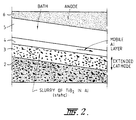
- the cathode used in the electrolysis cell of the present invention includes substrate 2, which may be a carbonaceous substrate or a carbon/TiB 2 composite substrate.
- a stable layer 3 comprising a slurry of TiB 2 particles in molten aluminium sits on top of the cathode. This stable layer of slurry acts as the top part of the cathode during operation of the aluminium reduction cell.
- Liquid aluminium metal is deposited as a thin film 4 on top of the slurry layer.
- the film of aluminium metal has the properties of a Newtonian fluid and the liquid aluminium flows downwardly as it is formed. It will be appreciated that the reduction cell shown in Figure 2 is being operated as a drained cathode cell. Electrolysis bath 5 and anode 6 are located above the cathode, as shown.
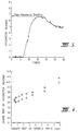
- FIG. 3 A typical plot of the viscometer reading versus time is shown in Figure 3.
- the viscometer reading is proportional to the torque supplied to the spindle.
- the torque-time response curve in Figure 3 is typical of a material which displays a yield stress.
- the peak in the curve corresponds to the time at which yielding in the material occurred.
- the viscometer readings corresponding to the peaks, in the Al/TiB 2 slurry tests, are plotted as square root of viscometer reading against the square root of the spindle speed in Figure 4.
- the viscometer reading is proportional to shear stress and the spindle speed is proportional to shear rate.
- the plot in Figure 4 indicates a linear relationship which, if extrapolated to zero spindle speed, zero shear rate, would have a non-zero viscometer reading, shear stress. This indicates that the Al/TiB 2 slurry displayed a yield stress.
- the yield stress of the slurry was measured by the technique of vane torsion developed by Dzuy and Boger, "Journal of Rheology,” 27(4), 1983, pp 321-349.
- a 4 bladed vane made from boron nitride was used to measure the yield stress of the Al/TiB 2 slurry at 1000°C.
- the yield stress of a number of AlTiB 2 slurries was measured at 1000°C using the technique of vane torsion as described above. The results are shown as a plot of yield stress (Pa) versus volume fraction TiB 2 in Figure 5. As can be seen from Figure 5, slurries containing 30 vol% TiB 2 have a yield stress of about 350 Pa, slurries containing 50 vol% TiB 2 have a yield stress of approximately 1500 Pa, whilst slurries containing 58 vol% TiB 2 have a yield stress of approximately 4000 Pa.
- a model was developed to estimate the shear stress to which an Al/TiB 2 slurry extended cathode might be subjected during DCC operation.
- the model considered the situation that occurs between one anode and the composite cathode in a single sloped cell.
- the shear stress that an Al/TiB 2 slurry would experience during cell operation was estimated to be about 1.9 Pa (assuming a cathode slope of 5°). This value could increase to about 16 Pa at the extremes of the operational variable values expected in operation of a drained cathode cell. The possible variation in slurry height and cathode slope would lead to the largest changes in shear stress.
- the yield stress of an Al/TiB 2 slurry with 50 volume % TiB 2 was measured to be about 1500 Pa at 1000°C as per Figure 5.
- the stress to which an Al/TiB 2 slurry would be subjected during typical DCC operation was calculated to be about 2 Pa.
- the maximum shear stress that could occur during normal DCC operation was calculated to be about 16 Pa. This suggests that the Al/TiB 2 slurry used in the yield stress measurements would remain static on the cathode surface during normal DCC operation.
- One possible methqd for forming the slurry layers required in the present invention involves applying a coating of a TiB 2 /carbon composite to the top part of a carbonaceous cathode.
- This coating is preferably of the order of 2.5 cm thick.
- the carbonaceous matrix in which the TiB 2 particles are held is eroded by exposure to molten aluminium and cryolite. This causes the carbon matrix to wear away and results in the formation of free particles of TiB 2 . If the particle size distribution and particle shapes of the TiB 2 particles is satisfactory, a slurry of Al/TiB 2 will form.
- Another possible method for producing the slurry layer involves placing TiB 2 powder of a desired particle size distribution and particle shapes on top of a carbon or composite substrate. Laboratory tests were carried out in which TiB 2 powder was placed on top of a substrate and exposed to aluminium and bath at 1000°C. The results indicate that a stable Al/TiB 2 slurry could be formed.
- Formation of the slurry by placing TiB 2 powder on the substrate has the potential to decrease substrate wear during operation of the cell shortly after start-up.
- the substrate is a TiB 2 /carbon composite
- use of TiB 2 powder to rapidly establish the slurry can greatly reduce wear of the composite.
- the amount of composite removed from a cathode under standard drained cathode all operating conditions during the first 2 years of cell life is estimated into be about 0.75 cm.
- the same cell would lose only about 0.3 cm of composite if an Al/TiB 2 slurry of 5 mm thickness was created on the cathode surface shortly after the cell was commissioned.
- Addition of TiB 2 powder could also be used to reinforce or reform the Al/TiB 2 slurry in areas where the slurry has been disrupted.
- the physical properties of the TiB 2 powder such as particle size distribution and particle shape, could be tailored to maximise the yield stress of the slurry, and thus would maximise the stability of the slurry.
- Addition of TiB 2 powder to an operational cell may also be used to repair or reinforce the slurry if the slurry is damaged or lost.
- a DCC cell was operated that had a cathode comprising an area of a TiB 2 /carbon composite and an area of graphitic cathode carbon.
- TiB 2 powder was added to the area of graphitic cathode carbon in an attempt to create an Al/TiB 2 slurry and assess its possible effects.
- the area of graphitic cathode carbon to which TiB 2 additions were made amounted to about 15 % of the total cathode area.
- the cell was cooled down and the cathode surface examined.
- a sample of the metal from one of these locations was examined using an electron microprobe (Cameca Camebax).
- the microprobe examination revealed that the metal consisted of a dense slurry of TiB 2 particles in Al as shown in the back scattered electron image in Figure 7.
- the content of TiB 2 particles was measured to be about 50 volume % and appeared to be uniform throughout the sample.
- Al 4 C 3 was observed at the interface between the slurry and the cathode carabon.
- the efficiency of the cell was the same as a cell with an entirely TiB 2 -carbon composite cathode which suggests the areas of Al/TiB 2 slurry on carbon must have been producing Al.
- the preferred embodiments described herein have described a drained cathode cell having a slurry of Al/TiB 2 on a cathode that includes a carbon substrate. It will be appreciated, however, that the invention encompasses a much wider range of substrate and cathode materials.
- the substrate could be any electrically conductive, aluminium material and the slurry could contain any aluminium resistant solid particles, whether wetted or not by liquid aluminium.
- the slurry possesses a sufficiently high viscosity or yield stress to remain immobile during cell operation and that the slurry completely covers the substrate.
- Slurry formation is particularly useful for the operation of drained cathode cells. Slurry formation may also be useful in operation of "standard" aluminium reduction cells, as the slurry layer may act as a diffusion barrier against substrate/cathode wear by Aluminium carbide formation.
- RHM materials consisting of 50 parts of TiB 2 hexagonal platelets sized from 40 to 70 ⁇ m and 50 parts of B 4 C platelets sized from 100 to 250 ⁇ m was thoroughly blended and sprayed with a solution of PVA onto all internal surfaces of a graphite crucible to form a tightly adhering layer of 2 - 3 mm in thickness.
- This coating was allowed to set and then an oxidation protection layer consisting of boron oxide powder and aluminium granules applied.
- the crucible was filled with bath and aluminium and heated up to the normal cell operating temperature and stirred for 24 hours to allow the aluminium to infiltrate the coating.
- the crucible was cooled, and autopsy showed that a slurry layer had formed.
- the wear of the TiB 2 /C composite cathode after 6 months of operation in the drained mode was found to be approximately 4 mm.
- This Example illustrates the formation of an Al/TiB 2 slurry using technology developed for production of metal matrix composites.
- 100 Kg of an aggregate of TiB 2 hexagonal platelets of +10 -100 ⁇ m can be combined with 50 kg Al to produce a metal matrix composite using any of the techniques known to be suitable for the production of metal matrix composites, such as those described in Kjar A.R., Mihelich J.L., Sritharan T. and Heathcock C.J., "Particle Reinforced Aluminium - Based Composites", Light-Weight Alloys for Aerospace Applications, Ed, Lee H.W., Chia E.H. and Kim N.J., TMS, 1989.
- the composite can be melted and cast into tiles measuring 30 cm x 30 cm x 1 cm thick.
- the solid tiles can be placed onto a TiB 2 -carbon composite cathode of a new drained cathode cell.
- the aluminium in the tiles Upon start-up of the cell the aluminium in the tiles will melt producing a drained cathode cell with a static Al/TiB 2 slurry of approximately 50 volume percent TiB 2 as the cathode.
- the yield stress of the slurry will be in the range of 1000-2000 Pa, as per Figaure 5.
- a drained cathode aluminium electrolysis cell was designed using the principles from US Patent No. 5,043,047. This cell incorporated a TiB 2 -carbon composite cathode that was produced with TiB 2 particles having sizes in the range of 10 ⁇ m to 1 mm. The cell was operated for 8 months. At the completion of the trial the cell was cooled and core samples of the TiB 2 -carbon composite cathode were obtained. Cross-sections of the core samples were examined using an electron microprobe (Cameca Camebax). A layer consisting of a dense slurry of TiB 2 particles in Al was observed on the composite surface in all samples. A back-scattered electron image of a typical Al/TiB 2 slurry layer is shown in Figure 11.
- the Al/TiB 2 slurry ranged in thickness up to 7 mm with an average of 2 mm.
- the TiB 2 particles in the slurry were of the same size range (10 ⁇ m - 1 mm), morphology and chemical composition as those in the underlying TiB 2 -carbon composite.
- Aluminium carbide (Al 4 C 2 ) was observed at the interface between the Al/TiB 2 slurry and the TiB 2 -carbon composite. This indicates that the Al/TiB 2 slurry formed as a result of removal of carbon from the composite via Al 4 C 3 formation.
- the concentration of the TiB 2 particles in the Al/TiB 2 slurry was measured to be about 55 volume percent. The slurry must have been essentially static during cell operation. Otherwise, if that amount of TiB 2 particles were continuously flowing off the cathode, the wear rate of the composite would have been much higher than observed.
Landscapes
- Chemical & Material Sciences (AREA)
- Engineering & Computer Science (AREA)
- Chemical Kinetics & Catalysis (AREA)
- Electrochemistry (AREA)
- Materials Engineering (AREA)
- Metallurgy (AREA)
- Organic Chemistry (AREA)
- Electrolytic Production Of Metals (AREA)
Claims (29)
- Elektrolysezelle zur Herstellung von Metall, bei der flüssiges Metall an oder angrenzend zu einer Oberseite einer Kathode abgeschieden wird und die Elektrolysezelle eine Anodenanordnung und eine unter der Anodenanordnung gelegene Kathode aufweist, wobei ein oberer Abschnitt der Kathode eine Ansammlung von im wesentlichen gegenüber dem flüssigen Metall nicht reaktiven Teilchen umfaßt und die Teilchen von derartiger Größe und Form sind, daß beim Betrieb der Zelle in zumindest einem oberen Teil der Ansammlung ein Schlamm aus flüssigem Metall und Teilchen aufgebaut wird, wobei der Schlamm eine im wesentlichen gleichmäßige Dispersion der Teilchen in einer durchgängigen Flüssigphase des flüssigen Metalls ist und der Schlamm eine Viskosität aufweist, die um wenigstens eine Größenordnung höher als die Viskosität des flüssigen Metalls ist, weshalb der Schlamm unter den Betriebsbedingungen der Zelle verhältnismäßig unbeweglich ist.
- Elektrolysezelle nach Anspruch 1, wobei der Schlamm plastisches Fließverhalten mit einer Fließspannung von wenigstens 10 N/m2 zeigt.
- Elektrolysezelle nach Anspruch 1 oder 2, wobei die Ansammlung von Teilchen Teilchen mit einer Teilchengröße zwischen 0,1 µm und 1 mm umfaßt.
- Elektrolysezelle nach Anspruch 3, wobei die Teilchen eine Teilchengröße zwischen 5 µm und 500 µm aufweisen.
- Elektrolysezelle nach einem der vorangehenden Ansprüche, wobei der Schlamm eine 1 bis 10 mm dicke Schicht ausbildet.
- Elektrolysezelle nach Anspruch 5, wobei der Schlamm eine 2 bis 5 mm dicke Schicht ausbildet.
- Elektrolysezelle nach einem der vorangehenden Ansprüche, wobei die Teilchen aus einem mit Metall benetzbaren Material bestehen.
- Elektrolysezelle nach Anspruch 7, wobei die Teilchen aus einem Borid, Karbid oder Nitrid eines hochschmelzenden Hartmetalls bestehen.
- Elektrolysezelle nach Anspruch 8, wobei die Teilchen Teilchen aus Titandiborid sind.
- Elektrolysezelle nach einem der vorangehenden Ansprüche, wobei die Ansammlung oben auf einem Kathodensubstratmaterial eine Sedimentationsschicht ausbildet.
- Elektrolysezelle nach einem der vorangehenden Ansprüche, wobei die Teilchen ein spezifisches Gewicht von wenigstens 2,5 g/cm3 aufweisen.
- Elektrolysezelle nach Anspruch 1 oder 2, wobei die Teilchen 25 bis 70 Volumenprozent des Schlamms umfassen.
- Elektrolysezelle nach einem der vorangehenden Ansprüche, wobei der Schlamm plastisches Fließverhalten mit einer Fließspannung von wenigstens 100 N/m2 zeigt.
- Elektrolysezelle nach einem der vorangehenden Ansprüche, wobei die Teilchen ein höheres spezifisches Gewicht als das flüssige Metall aufweisen.
- Elektrolysezelle nach einem der vorangehenden Ansprüche, wobei die Teilchen gegenüber einem Elektrolysebad in der Zelle im wesentlichen nicht reaktiv sind.
- Elektrolysezelle nach einem der vorangehenden Ansprüche, wobei die Teilchen elektrisch leitfähig sind.
- Verfahren zur Herstellung eines Metalls durch Elektrolyse in einer Elektrolysezelle, die eine obere Anode, eine untere Kathode und dazwischen ein Elektrolysebad umfaßt, bei dem flüssiges Metall an oder angrenzend zu einer Oberseite der Kathode abgeschieden wird, wobei ein oberer Abschnitt der Kathode eine Ansammlung von im wesentlichen gegenüber dem flüssigen Metall nicht reaktiven Teilchen umfaßt und das Verfahren dadurch gekennzeichnet ist, daß in zumindest einem oberen Teil der Ansammlung ein Schlamm aus flüssigem Metall und Teilchen aufgebaut wird, wobei der Schlamm eine im wesentlichen gleichmäßige Dispersion der Teilchen in einer durchgängigen Flüssigphase des flüssigen Metalls ist und der Schlamm eine Viskosität aufweist, die um wenigstens eine Größenordnung höher als die Viskosität des flüssigen Metalls ist, weshalb der Schlamm unter den Betriebsbedingungen der Zelle verhältnismäßig unbeweglich ist.
- Verfahren nach Anspruch 17, wobei der Schlamm plastisches Fließverhalten mit einer Fließspannung von wenigstens 10 N/m2 zeigt.
- Verfahren nach Anspruch 17 oder Anspruch 18, wobei die Ansammlung von Teilchen eine Sedimentationsschicht auf einem Kathodensubstratmaterial umfaßt.
- Verfahren nach einem der Ansprüche 17 bis 19, wobei die Teilchen eine Teilchengröße zwischen 0,1 µm und 1 mm aufweisen.
- Verfahren nach einem der Ansprüche 17 bis 20, wobei der Schlamm eine 1 bis 10 mm dicke Schicht ausbildet.
- Verfahren nach einem der Ansprüche 17 bis 21, wobei die Teilchen aus einem mit Metall benetzbaren Material bestehen.
- Verfahren nach einem der Ansprüche 17 bis 22, wobei das Metall Aluminium ist und die Teilchen aus einem Karbid, Borid oder Nitrid eines hochschmelzenden Hartmetalls bestehen.
- Verfahren nach einem der Ansprüche 17 bis 23, wobei der Schlamm plastisches Fließverhalten mit einer Fließspannung von wenigstens 100 N/m2 zeigt.
- Verfahren nach einem der Ansprüche 17 bis 24, wobei die Zelle als eine Ablaufkathode betrieben wird, bei der kontinuierlich flüssiges Metall auf einer Oberseite des Schlamms abgeschieden wird und abläuft, wodurch oben auf dem Schlamm ein dünner Film aus flüssigem Metall ausgebildet wird.
- Verfahren nach einem der Ansprüche 17 bis 25, wobei der Schlamm durch einen aus der folgenden Aufzählung ausgewählten Verfahrensweg aufgebaut wird:a) vor dem Anfahren der Zelle Aufbringen eines Gemischs aus Teilchen und Bindemittel auf eine Kathode, wobei dieses Gemisch aus Teilchen und Bindemittel während des Betriebs der Zelle von flüssigem Metall infiltriert wird, so daß der Schlamm ausgebildet wird;b) während des Betriebs Einbringen von Teilchen mit der gewünschten Teilchengrößenverteilung und Teilchenform in die Zelle, wodurch sich die Teilchen zur Ausbildung des Schlamms auf der Kathode absetzen;c) während des Betriebs der Zelle Aufbringen eines Schlamms aus flüssigem Metall und Teilchen auf die Oberseite der Kathode;d) vor oder während des Zellenanfahrens Aufbringen eines Blechs oder einer Platte aus einem Metallmatrix-Verbundstoff auf die Kathode, wobei der Metallmatrix-Verbundstoff während des Zellenbetriebs aufschmilzt, so daß der Schlamm ausgebildet wird; odere) vor oder während des Anfahrens Aufbringen einer ungebundenen Ansammlung von Teilchen auf die Kathode, wobei diese Ansammlung während des Zellenbetriebs von flüssigem Metall infiltriert wird, so daß der Schlamm ausgebildet wird.
- Verfahren nach einem der Ansprüche 17 bis 26, wobei die Teilchen ein höheres spezifisches Gewicht als das flüssige Metall aufweisen.
- Verfahren nach einem der Ansprüche 17 bis 26, wobei die Teilchen gegenüber dem Elektrolysebad in der Zelle im wesentlichen nicht reaktiv sind.
- Verfahren nach einem der Ansprüche 17 bis 26, wobei die Teilchen elektrisch leitfähig sind.
Applications Claiming Priority (4)
| Application Number | Priority Date | Filing Date | Title |
|---|---|---|---|
| AUPL641292 | 1992-12-17 | ||
| AUPL641292 | 1992-12-17 | ||
| AUPL6412/92 | 1992-12-17 | ||
| PCT/AU1993/000661 WO1994013861A1 (en) | 1992-12-17 | 1993-12-17 | Electrolysis cell for metal production |
Publications (3)
| Publication Number | Publication Date |
|---|---|
| EP0675974A1 EP0675974A1 (de) | 1995-10-11 |
| EP0675974A4 EP0675974A4 (de) | 1996-03-06 |
| EP0675974B1 true EP0675974B1 (de) | 1999-07-21 |
Family
ID=3776604
Family Applications (1)
| Application Number | Title | Priority Date | Filing Date |
|---|---|---|---|
| EP94903688A Expired - Lifetime EP0675974B1 (de) | 1992-12-17 | 1993-12-17 | Elektrolysezelle für die herstellung von metallen |
Country Status (8)
| Country | Link |
|---|---|
| US (1) | US5658447A (de) |
| EP (1) | EP0675974B1 (de) |
| AT (1) | ATE182370T1 (de) |
| CA (1) | CA2152048C (de) |
| DE (1) | DE69325720T2 (de) |
| NO (1) | NO313104B1 (de) |
| WO (1) | WO1994013861A1 (de) |
| ZA (1) | ZA939468B (de) |
Families Citing this family (26)
| Publication number | Priority date | Publication date | Assignee | Title |
|---|---|---|---|---|
| AU5085698A (en) * | 1996-10-18 | 1998-05-15 | Moltech Invent S.A. | The start-up of aluminium electrowinning cells |
| US6638412B2 (en) * | 2000-12-01 | 2003-10-28 | Moltech Invent S.A. | Prevention of dissolution of metal-based aluminium production anodes |
| DE102010038669A1 (de) * | 2010-07-29 | 2012-02-02 | Sgl Carbon Se | Kathodenblock für eine Aluminium-Elektrolysezelle und ein Verfahren zu seiner Herstellung |
| DE102011004014A1 (de) * | 2011-02-11 | 2012-08-16 | Sgl Carbon Se | Kathodenblock mit einer Hartstoff enthaltenden Deckschicht |
| DE102011004013A1 (de) * | 2011-02-11 | 2012-08-16 | Sgl Carbon Se | Graphitierter Kathodenblock mit einer abrasionsbeständigen Oberfläche |
| CA2888463C (en) | 2012-10-16 | 2021-01-26 | Ambri Inc. | Electrochemical energy storage devices and housings |
| US11387497B2 (en) | 2012-10-18 | 2022-07-12 | Ambri Inc. | Electrochemical energy storage devices |
| US10541451B2 (en) | 2012-10-18 | 2020-01-21 | Ambri Inc. | Electrochemical energy storage devices |
| US11211641B2 (en) | 2012-10-18 | 2021-12-28 | Ambri Inc. | Electrochemical energy storage devices |
| US9312522B2 (en) | 2012-10-18 | 2016-04-12 | Ambri Inc. | Electrochemical energy storage devices |
| US9520618B2 (en) | 2013-02-12 | 2016-12-13 | Ambri Inc. | Electrochemical energy storage devices |
| US11721841B2 (en) | 2012-10-18 | 2023-08-08 | Ambri Inc. | Electrochemical energy storage devices |
| US9735450B2 (en) | 2012-10-18 | 2017-08-15 | Ambri Inc. | Electrochemical energy storage devices |
| US10270139B1 (en) | 2013-03-14 | 2019-04-23 | Ambri Inc. | Systems and methods for recycling electrochemical energy storage devices |
| US9502737B2 (en) | 2013-05-23 | 2016-11-22 | Ambri Inc. | Voltage-enhanced energy storage devices |
| US12347832B2 (en) | 2013-09-18 | 2025-07-01 | Ambri, LLC | Electrochemical energy storage devices |
| DK3058605T3 (da) | 2013-10-16 | 2024-03-04 | Ambri Inc | Tætninger til anordninger af reaktivt højtemperaturmateriale |
| WO2015058165A1 (en) | 2013-10-17 | 2015-04-23 | Ambri Inc. | Battery management systems for energy storage devices |
| US12142735B1 (en) | 2013-11-01 | 2024-11-12 | Ambri, Inc. | Thermal management of liquid metal batteries |
| US10181800B1 (en) | 2015-03-02 | 2019-01-15 | Ambri Inc. | Power conversion systems for energy storage devices |
| WO2016141354A2 (en) | 2015-03-05 | 2016-09-09 | Ambri Inc. | Ceramic materials and seals for high temperature reactive material devices |
| US11339490B2 (en) * | 2015-04-23 | 2022-05-24 | United Company RUSAL Engineering and Technology Centre LLC | Aluminum electrolyzer electrode (variants) |
| US9893385B1 (en) | 2015-04-23 | 2018-02-13 | Ambri Inc. | Battery management systems for energy storage devices |
| US11929466B2 (en) | 2016-09-07 | 2024-03-12 | Ambri Inc. | Electrochemical energy storage devices |
| EP3607603A4 (de) | 2017-04-07 | 2021-01-13 | Ambri Inc. | Schmelzsalzbatterie mit fester metallkathode |
| AU2019405440A1 (en) | 2018-12-17 | 2021-08-12 | Ambri, LLC | High temperature energy storage systems and methods |
Family Cites Families (22)
| Publication number | Priority date | Publication date | Assignee | Title |
|---|---|---|---|---|
| US3459515A (en) * | 1964-03-31 | 1969-08-05 | Du Pont | Cermets of aluminum with titanium carbide and titanium and zirconium borides |
| US3616045A (en) * | 1969-02-17 | 1971-10-26 | Tatabanyai Aluminiumkoho | Process for increasing the strength and electrical conductivity of graphite or carbon articles and/or for bonding such articles to each other to ceramic articles or to metals |
| US3723287A (en) * | 1970-09-30 | 1973-03-27 | C Elliott | Apparatus for producing aluminum from alumina |
| US4231853A (en) * | 1979-04-27 | 1980-11-04 | Ppg Industries, Inc. | Cathodic current conducting elements for use in aluminum reduction cells |
| CH643600A5 (de) * | 1979-12-05 | 1984-06-15 | Alusuisse | Elektrolysezelle zur herstellung von aluminium. |
| GB2069530B (en) * | 1980-01-28 | 1984-05-16 | Diamond Shamrock Corp | Packed cathode bed for electrowinning metals from fused salts |
| CH644406A5 (de) * | 1980-04-03 | 1984-07-31 | Alusuisse | Schmelzflusselektrolysezelle zur herstellung von aluminium. |
| ZA824255B (en) * | 1981-06-25 | 1983-05-25 | Alcan Int Ltd | Electrolytic reduction cells |
| EP0092525A1 (de) * | 1982-04-21 | 1983-10-26 | Diamond Shamrock Corporation | Nichtbenetzbare Füllkörper für eine Elektrolysezelle zur Herstellung von Aluminium |
| ATE32107T1 (de) * | 1982-05-10 | 1988-02-15 | Eltech Systems Corp | Aluminium benetzbare materialien. |
| US4560448A (en) * | 1982-05-10 | 1985-12-24 | Eltech Systems Corporation | Aluminum wettable materials for aluminum production |
| DE3369162D1 (en) * | 1982-05-10 | 1987-02-19 | Eltech Systems Corp | Dimensionally stable drained aluminum electrowinning cathode method and apparatus |
| EP0109358A1 (de) * | 1982-11-15 | 1984-05-23 | Schweizerische Aluminium Ag | Kathode für eine Schmelzflusselektrolysezelle |
| CA1235001A (en) * | 1982-12-30 | 1988-04-12 | Thomas P. Deangelis | Reaction sintered cermet |
| US4500643A (en) * | 1982-12-30 | 1985-02-19 | Alcan International Limited | Shaped refractory metal boride articles and method of making them |
| US4605634A (en) * | 1982-12-30 | 1986-08-12 | Corning Glass Works | Reaction sintered oxide-boride |
| CA1211474A (en) * | 1982-12-30 | 1986-09-16 | Corning Glass Works | Reaction sintered oxide-boride |
| US4746363A (en) * | 1982-12-30 | 1988-05-24 | Corning Glass Works | Reaction sintered cermet |
| GB8331769D0 (en) * | 1983-11-29 | 1984-01-04 | Alcan Int Ltd | Aluminium reduction cells |
| ES8602154A1 (es) * | 1983-11-29 | 1985-11-01 | Alcan Int Ltd | Una instalacion de cuba electrolitica de reduccion de aluminio. |
| GB8522138D0 (en) * | 1985-09-06 | 1985-10-09 | Alcan Int Ltd | Linings for aluminium reduction cells |
| US5227045A (en) * | 1989-01-09 | 1993-07-13 | Townsend Douglas W | Supersaturation coating of cathode substrate |
-
1993
- 1993-12-17 EP EP94903688A patent/EP0675974B1/de not_active Expired - Lifetime
- 1993-12-17 US US08/454,183 patent/US5658447A/en not_active Expired - Lifetime
- 1993-12-17 AT AT94903688T patent/ATE182370T1/de not_active IP Right Cessation
- 1993-12-17 WO PCT/AU1993/000661 patent/WO1994013861A1/en not_active Ceased
- 1993-12-17 CA CA002152048A patent/CA2152048C/en not_active Expired - Fee Related
- 1993-12-17 ZA ZA939468A patent/ZA939468B/xx unknown
- 1993-12-17 DE DE69325720T patent/DE69325720T2/de not_active Expired - Lifetime
-
1995
- 1995-06-16 NO NO19952419A patent/NO313104B1/no not_active IP Right Cessation
Also Published As
| Publication number | Publication date |
|---|---|
| CA2152048A1 (en) | 1994-06-23 |
| NO952419L (no) | 1995-08-08 |
| NO313104B1 (no) | 2002-08-12 |
| CA2152048C (en) | 2004-06-29 |
| DE69325720D1 (de) | 1999-08-26 |
| EP0675974A1 (de) | 1995-10-11 |
| NO952419D0 (no) | 1995-06-16 |
| ATE182370T1 (de) | 1999-08-15 |
| ZA939468B (en) | 1994-08-10 |
| DE69325720T2 (de) | 2000-04-06 |
| WO1994013861A1 (en) | 1994-06-23 |
| EP0675974A4 (de) | 1996-03-06 |
| US5658447A (en) | 1997-08-19 |
Similar Documents
| Publication | Publication Date | Title |
|---|---|---|
| US5658447A (en) | Electrolysis cell and method for metal production | |
| US4333813A (en) | Cathodes for alumina reduction cells | |
| US5753163A (en) | Production of bodies of refractory borides | |
| US5227045A (en) | Supersaturation coating of cathode substrate | |
| NO166119B (no) | Reaksjonssintret cermetlegeme, fremgangsmaate for dets fremstilling samt elektrolytisk aluminiumproduksjonscelle og komponent deri. | |
| US5028301A (en) | Supersaturation plating of aluminum wettable cathode coatings during aluminum smelting in drained cathode cells | |
| AU670496B2 (en) | The bonding of bodies of refractory hard materials to carbonaceous supports | |
| EP0215590A1 (de) | Innenauskleidungen für Aluminium-Reduktionszellen | |
| AU679029B2 (en) | Electrolysis cell for metal production | |
| EP1395529B1 (de) | Kohlenstoffkacheln mit feuerfester beschichtung für hochtemperaturanwendungen | |
| Brown | The Wettability of TiB2-Based Cathodoes in Low-Temperature Slurry-Electrolyte Reduction Cells | |
| Øye et al. | Properties of a Colloidal Alumina-Bonded TiB2 Coating on Cathode Carbon Materials | |
| EP0102186A2 (de) | Zelle für die elektrolytische Aluminiumherstellung | |
| EP1366214B1 (de) | Aluminiumbenetzbares poröses keramisches material | |
| NO166581B (no) | Reaksjonssintret, flerfaset keramisk legeme, komponent i aluminiumproduksjonscelle samt en slik celle. | |
| Sekhar et al. | A porous titanium diboride composite cathode coating for Hall-Héroult cells: Part I. Thin coatings | |
| Heidari | Development of wettable cathode for aluminium smelting | |
| WO2002096830A1 (en) | Carbon tiles with refractory coating for use at elevated temperature | |
| Xue et al. | Investigating carbon/TiB2 materials for aluminum reduction cathodes | |
| AU690087B2 (en) | Refractory/carbon components of aluminium production cells | |
| Wendt et al. | Erosion of sintered TiB2-cathodes during cathodic aluminium deposition from LiCl/AlCl3 melts | |
| Schilling | Laboratory Testing of TiB sub 2-Based Cathodes for Electrolytic Production of Aluminum | |
| AU2002304402A1 (en) | Carbon tiles with refratory coating for use at elevated temperature | |
| AU2002236143A1 (en) | Aluminium-wettable porous ceramic material |
Legal Events
| Date | Code | Title | Description |
|---|---|---|---|
| PUAI | Public reference made under article 153(3) epc to a published international application that has entered the european phase |
Free format text: ORIGINAL CODE: 0009012 |
|
| 17P | Request for examination filed |
Effective date: 19950707 |
|
| AK | Designated contracting states |
Kind code of ref document: A1 Designated state(s): AT BE CH DE DK ES FR GB GR IE IT LI LU MC NL PT SE |
|
| A4 | Supplementary search report drawn up and despatched |
Effective date: 19960119 |
|
| AK | Designated contracting states |
Kind code of ref document: A4 Designated state(s): AT BE CH DE DK ES FR GB GR IE IT LI LU MC NL PT SE |
|
| 17Q | First examination report despatched |
Effective date: 19961120 |
|
| GRAG | Despatch of communication of intention to grant |
Free format text: ORIGINAL CODE: EPIDOS AGRA |
|
| GRAG | Despatch of communication of intention to grant |
Free format text: ORIGINAL CODE: EPIDOS AGRA |
|
| GRAH | Despatch of communication of intention to grant a patent |
Free format text: ORIGINAL CODE: EPIDOS IGRA |
|
| GRAH | Despatch of communication of intention to grant a patent |
Free format text: ORIGINAL CODE: EPIDOS IGRA |
|
| GRAA | (expected) grant |
Free format text: ORIGINAL CODE: 0009210 |
|
| AK | Designated contracting states |
Kind code of ref document: B1 Designated state(s): AT BE CH DE DK ES FR GB GR IE IT LI LU MC NL PT SE |
|
| PG25 | Lapsed in a contracting state [announced via postgrant information from national office to epo] |
Ref country code: LI Free format text: LAPSE BECAUSE OF FAILURE TO SUBMIT A TRANSLATION OF THE DESCRIPTION OR TO PAY THE FEE WITHIN THE PRESCRIBED TIME-LIMIT Effective date: 19990721 Ref country code: GR Free format text: LAPSE BECAUSE OF NON-PAYMENT OF DUE FEES Effective date: 19990721 Ref country code: ES Free format text: THE PATENT HAS BEEN ANNULLED BY A DECISION OF A NATIONAL AUTHORITY Effective date: 19990721 Ref country code: CH Free format text: LAPSE BECAUSE OF FAILURE TO SUBMIT A TRANSLATION OF THE DESCRIPTION OR TO PAY THE FEE WITHIN THE PRESCRIBED TIME-LIMIT Effective date: 19990721 Ref country code: BE Free format text: LAPSE BECAUSE OF FAILURE TO SUBMIT A TRANSLATION OF THE DESCRIPTION OR TO PAY THE FEE WITHIN THE PRESCRIBED TIME-LIMIT Effective date: 19990721 Ref country code: AT Free format text: LAPSE BECAUSE OF FAILURE TO SUBMIT A TRANSLATION OF THE DESCRIPTION OR TO PAY THE FEE WITHIN THE PRESCRIBED TIME-LIMIT Effective date: 19990721 |
|
| REF | Corresponds to: |
Ref document number: 182370 Country of ref document: AT Date of ref document: 19990815 Kind code of ref document: T |
|
| REG | Reference to a national code |
Ref country code: CH Ref legal event code: EP |
|
| REF | Corresponds to: |
Ref document number: 69325720 Country of ref document: DE Date of ref document: 19990826 |
|
| REG | Reference to a national code |
Ref country code: IE Ref legal event code: FG4D |
|
| ITF | It: translation for a ep patent filed | ||
| PG25 | Lapsed in a contracting state [announced via postgrant information from national office to epo] |
Ref country code: PT Free format text: LAPSE BECAUSE OF FAILURE TO SUBMIT A TRANSLATION OF THE DESCRIPTION OR TO PAY THE FEE WITHIN THE PRESCRIBED TIME-LIMIT Effective date: 19991021 Ref country code: DK Free format text: LAPSE BECAUSE OF FAILURE TO SUBMIT A TRANSLATION OF THE DESCRIPTION OR TO PAY THE FEE WITHIN THE PRESCRIBED TIME-LIMIT Effective date: 19991021 |
|
| ET | Fr: translation filed | ||
| PG25 | Lapsed in a contracting state [announced via postgrant information from national office to epo] |
Ref country code: LU Free format text: LAPSE BECAUSE OF NON-PAYMENT OF DUE FEES Effective date: 19991217 Ref country code: IE Free format text: LAPSE BECAUSE OF NON-PAYMENT OF DUE FEES Effective date: 19991217 |
|
| REG | Reference to a national code |
Ref country code: CH Ref legal event code: PL |
|
| PLBE | No opposition filed within time limit |
Free format text: ORIGINAL CODE: 0009261 |
|
| STAA | Information on the status of an ep patent application or granted ep patent |
Free format text: STATUS: NO OPPOSITION FILED WITHIN TIME LIMIT |
|
| PG25 | Lapsed in a contracting state [announced via postgrant information from national office to epo] |
Ref country code: MC Free format text: LAPSE BECAUSE OF NON-PAYMENT OF DUE FEES Effective date: 20000630 |
|
| 26N | No opposition filed | ||
| REG | Reference to a national code |
Ref country code: IE Ref legal event code: MM4A |
|
| REG | Reference to a national code |
Ref country code: GB Ref legal event code: IF02 |
|
| PGFP | Annual fee paid to national office [announced via postgrant information from national office to epo] |
Ref country code: NL Payment date: 20091224 Year of fee payment: 17 |
|
| PGFP | Annual fee paid to national office [announced via postgrant information from national office to epo] |
Ref country code: GB Payment date: 20091229 Year of fee payment: 17 |
|
| PGFP | Annual fee paid to national office [announced via postgrant information from national office to epo] |
Ref country code: IT Payment date: 20091230 Year of fee payment: 17 |
|
| PGFP | Annual fee paid to national office [announced via postgrant information from national office to epo] |
Ref country code: DE Payment date: 20091230 Year of fee payment: 17 |
|
| PGFP | Annual fee paid to national office [announced via postgrant information from national office to epo] |
Ref country code: SE Payment date: 20091230 Year of fee payment: 17 |
|
| REG | Reference to a national code |
Ref country code: NL Ref legal event code: V1 Effective date: 20110701 |
|
| GBPC | Gb: european patent ceased through non-payment of renewal fee |
Effective date: 20101217 |
|
| REG | Reference to a national code |
Ref country code: SE Ref legal event code: EUG |
|
| PG25 | Lapsed in a contracting state [announced via postgrant information from national office to epo] |
Ref country code: SE Free format text: LAPSE BECAUSE OF NON-PAYMENT OF DUE FEES Effective date: 20101218 |
|
| REG | Reference to a national code |
Ref country code: DE Ref legal event code: R119 Ref document number: 69325720 Country of ref document: DE Effective date: 20110701 |
|
| PG25 | Lapsed in a contracting state [announced via postgrant information from national office to epo] |
Ref country code: GB Free format text: LAPSE BECAUSE OF NON-PAYMENT OF DUE FEES Effective date: 20101217 Ref country code: DE Free format text: LAPSE BECAUSE OF NON-PAYMENT OF DUE FEES Effective date: 20110701 |
|
| PG25 | Lapsed in a contracting state [announced via postgrant information from national office to epo] |
Ref country code: NL Free format text: LAPSE BECAUSE OF NON-PAYMENT OF DUE FEES Effective date: 20110701 Ref country code: IT Free format text: LAPSE BECAUSE OF NON-PAYMENT OF DUE FEES Effective date: 20101217 |
|
| PGFP | Annual fee paid to national office [announced via postgrant information from national office to epo] |
Ref country code: FR Payment date: 20120104 Year of fee payment: 19 |
|
| REG | Reference to a national code |
Ref country code: FR Ref legal event code: ST Effective date: 20130830 |
|
| PG25 | Lapsed in a contracting state [announced via postgrant information from national office to epo] |
Ref country code: FR Free format text: LAPSE BECAUSE OF NON-PAYMENT OF DUE FEES Effective date: 20130102 |