EP0675774B1 - Improvements in or relating to self-piercing riveting - Google Patents
Improvements in or relating to self-piercing riveting Download PDFInfo
- Publication number
- EP0675774B1 EP0675774B1 EP94902918A EP94902918A EP0675774B1 EP 0675774 B1 EP0675774 B1 EP 0675774B1 EP 94902918 A EP94902918 A EP 94902918A EP 94902918 A EP94902918 A EP 94902918A EP 0675774 B1 EP0675774 B1 EP 0675774B1
- Authority
- EP
- European Patent Office
- Prior art keywords
- sheet material
- clamping
- rivet
- riveting
- punch
- Prior art date
- Legal status (The legal status is an assumption and is not a legal conclusion. Google has not performed a legal analysis and makes no representation as to the accuracy of the status listed.)
- Expired - Lifetime
Links
Images

Classifications
-
- B—PERFORMING OPERATIONS; TRANSPORTING
- B21—MECHANICAL METAL-WORKING WITHOUT ESSENTIALLY REMOVING MATERIAL; PUNCHING METAL
- B21J—FORGING; HAMMERING; PRESSING METAL; RIVETING; FORGE FURNACES
- B21J15/00—Riveting
- B21J15/02—Riveting procedures
-
- B—PERFORMING OPERATIONS; TRANSPORTING
- B21—MECHANICAL METAL-WORKING WITHOUT ESSENTIALLY REMOVING MATERIAL; PUNCHING METAL
- B21J—FORGING; HAMMERING; PRESSING METAL; RIVETING; FORGE FURNACES
- B21J15/00—Riveting
- B21J15/10—Riveting machines
-
- B—PERFORMING OPERATIONS; TRANSPORTING
- B21—MECHANICAL METAL-WORKING WITHOUT ESSENTIALLY REMOVING MATERIAL; PUNCHING METAL
- B21J—FORGING; HAMMERING; PRESSING METAL; RIVETING; FORGE FURNACES
- B21J15/00—Riveting
- B21J15/02—Riveting procedures
- B21J15/025—Setting self-piercing rivets
-
- Y—GENERAL TAGGING OF NEW TECHNOLOGICAL DEVELOPMENTS; GENERAL TAGGING OF CROSS-SECTIONAL TECHNOLOGIES SPANNING OVER SEVERAL SECTIONS OF THE IPC; TECHNICAL SUBJECTS COVERED BY FORMER USPC CROSS-REFERENCE ART COLLECTIONS [XRACs] AND DIGESTS
- Y10—TECHNICAL SUBJECTS COVERED BY FORMER USPC
- Y10T—TECHNICAL SUBJECTS COVERED BY FORMER US CLASSIFICATION
- Y10T29/00—Metal working
- Y10T29/49—Method of mechanical manufacture
- Y10T29/49826—Assembling or joining
- Y10T29/49833—Punching, piercing or reaming part by surface of second part
- Y10T29/49835—Punching, piercing or reaming part by surface of second part with shaping
- Y10T29/49837—Punching, piercing or reaming part by surface of second part with shaping of first part
-
- Y—GENERAL TAGGING OF NEW TECHNOLOGICAL DEVELOPMENTS; GENERAL TAGGING OF CROSS-SECTIONAL TECHNOLOGIES SPANNING OVER SEVERAL SECTIONS OF THE IPC; TECHNICAL SUBJECTS COVERED BY FORMER USPC CROSS-REFERENCE ART COLLECTIONS [XRACs] AND DIGESTS
- Y10—TECHNICAL SUBJECTS COVERED BY FORMER USPC
- Y10T—TECHNICAL SUBJECTS COVERED BY FORMER US CLASSIFICATION
- Y10T29/00—Metal working
- Y10T29/49—Method of mechanical manufacture
- Y10T29/49826—Assembling or joining
- Y10T29/49947—Assembling or joining by applying separate fastener
- Y10T29/49954—Fastener deformed after application
- Y10T29/49956—Riveting
-
- Y—GENERAL TAGGING OF NEW TECHNOLOGICAL DEVELOPMENTS; GENERAL TAGGING OF CROSS-SECTIONAL TECHNOLOGIES SPANNING OVER SEVERAL SECTIONS OF THE IPC; TECHNICAL SUBJECTS COVERED BY FORMER USPC CROSS-REFERENCE ART COLLECTIONS [XRACs] AND DIGESTS
- Y10—TECHNICAL SUBJECTS COVERED BY FORMER USPC
- Y10T—TECHNICAL SUBJECTS COVERED BY FORMER US CLASSIFICATION
- Y10T29/00—Metal working
- Y10T29/53—Means to assemble or disassemble
- Y10T29/5343—Means to drive self-piercing work part
-
- Y—GENERAL TAGGING OF NEW TECHNOLOGICAL DEVELOPMENTS; GENERAL TAGGING OF CROSS-SECTIONAL TECHNOLOGIES SPANNING OVER SEVERAL SECTIONS OF THE IPC; TECHNICAL SUBJECTS COVERED BY FORMER USPC CROSS-REFERENCE ART COLLECTIONS [XRACs] AND DIGESTS
- Y10—TECHNICAL SUBJECTS COVERED BY FORMER USPC
- Y10T—TECHNICAL SUBJECTS COVERED BY FORMER US CLASSIFICATION
- Y10T29/00—Metal working
- Y10T29/53—Means to assemble or disassemble
- Y10T29/53709—Overedge assembling means
- Y10T29/5377—Riveter
Definitions
- This invention relates to self-piercing riveting and more particularly to a method of and apparatus for riveting of the kind in which a self-piercing rivet is inserted into sheet material without full penetration, such that the deformed end of the rivet remains encapsulated by an upset annulus of the sheet material (See for example "Engineering", vol. 222, September 1982, London GB, pages 634 - 635 and EP-A-2 350 901).
- Fig. 1 is a diagrammatic section of an example of a riveted joint made by such a riveting method in accordance with the invention.
- a rivet 1 has a head 2 and a shank 3 terminating in an annular edge 4.
- the shank 3 is initially cylindrical but is flared outwardly into the illustrated shape as the rivet is driven into two overlapping sheets 5, 6 located on a suitably shaped die. As shown, the shank 3 and the edge 4 of the rivet remain embedded in the sheet material 5, 6 after the rivet has been set.
- riveted joints of the kind illustrated in Fig. 1 have had various imperfections.
- the head 2 of the rivet 1 is flush with the surrounding surface of the sheet 5 which should remain undeformed, and the annular valley 7 between the sheet 5 and the rivet head 2 should be as shallow as possible.
- the riveting stresses may cause substantial deformation of the upper sheet 5, for example in the form of a circular depression or dimple around the rivet location, and the valley 7 may be unacceptably deep.
- surface distortions are often unacceptable, e.g. for visible joints of motor vehicle body panels, in particular the curved portions of said panels.
- the appearance is immaterial but unevennesses in the thickness of the sheet material 6 encapsulating the rivet end 4 may affect the strength of the joint and permit breakthrough of the rivet end thereby encouraging corrosion.
- the invention also relates to a riveting machine for setting self-piercing rivets in the manner described.
- a known riveting machine for setting self-piercing rivets is described in European Patent Specification 172171 by Nietek Pty. Ltd. the disclosure of which is incorporated herein by reference.
- a method of riveting comprising inserting a self-piercing rivet into sheet material without full penetration such that the deformed end of the rivet remains encapsulated by an upset annulus of the sheet material characterised in that the sheet material is clamped with a substantial force during the riveting operation in the region around the rivet insertion location.
- a riveting machine for inserting a self-piercing rivet into sheet material without full penetration such that the deformed end of the rivet remains encapsulated by an upset annulus of the sheet material, said machine comprising a punch, means for feeding rivets successively to the punch for insertion into sheet material to be riveted, a die aligned with the punch for deforming the rivet inserted thereby, and clamping means for clamping the sheet material with a substantial force during the riveting operation in the region around the rivet insertion location.
- the riveted joint of Fig. 1 has already been described as an example of the kind of joint that is produced by the riveting method of the invention.
- the undeformed rivet is shown in Fig. 3 and is given the same reference numerals.
- the shank 3 is initially cylindrical and the free end 4 has an internal taper to define a cutting edge facilitating insertion and spreading of the rivet.
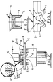
- Fig. 2 shows a punch 10 of a riveting tool surrounded by a preclamping element 11 having an annular clamping surface 12 urging two overlapping sheets 13, 14 against a die 15.
- the surface 12 may have a rough finish provided for example by knurling or annular grooving in order to improve the grip on the sheet material and prevent material being pulled laterally into the joint.
- a coining ring may be provided on the surface 12 as shown in the inset to Fig. 2. The coining ring functions to prevent material flow and also to regulate distortion adjacent to the rivet head so as to give a uniform appearance.
- a rivet 16 of the kind shown in Fig. 3 is located at the end of the punch 10 ready for insertion into the sheets 13, 14.
- the die 15 has an annular surface 17 (which may be roughened in the same way as the surface 12) cooperating with the clamping surface 12 and surrounding a semi-toroidal cavity 18 around a central projection 19 which is preferably above the level of the clamping surface 17 but may also be below or at the same level as said surface.
- the clamping element 12 exerts a constant clamping force on the sheets 13, 14.
- An electronic pressure switch senses the clamping pressure and main riveting process pressure and is used as a control device coordinated by a programmable logic controller.
- the clamping force which remains constant during the riveting process, can be accurately set at any value up to approximately 1.5 tonnes.
- the control of the clamping force may involve topping up of the oil in the clamping cylinder to maintain the clamping pressure as the riveting process takes place. This is required because the frame of the riveting machine, which is a C-Frame in the machine shown in European Patent Specification No. 172171, deflects during the riveting operation and the clamp cylinder must therefore advance to maintain the clamping force constant.
- the tapered end 4 of the rivet 1 provides a cutting ring which shears the top sheet 13 with minimal draw of the sheet material as a result of the clamping force.
- the taper angle on the end of the rivet provides a taper surface which can be thrust radially outwards by the reaction of the die and punch giving reliable spreading of the rivet as it is forced into the die by the punch.
- the rivet is preferably heat treated to improve its self-piercing quality.
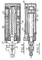
- the riveting machine is preferably constructed as shown in the aforesaid European Patent Specification. Alternative designs of the clamping and punching part of the machine are shown in Figs. 4, 5 and Figs. 6, 7.
- a punch 20 is carried by a plunger 21 terminating in a double-acting piston 22 slidable in a main cylinder 23 having inlet/outlet connections 24, 25 at opposite sides of the piston 22.
- the lower part of the plunger 21 (to the left in Figs. 4 and 5) is slidable in a guide bush 26 which carries an actuator 27 and terminates in a nose 28 the end face of which provides the clamping surface 12 of Fig. 2.
- the nose 28 of the tool is advanced to contact the workpiece by introducing fluid under pressure through the connection 32.
- a predetermined clamping force is then exerted on the nose 28 by pressurising the cylinder 31 so as to advance the sleeve 30.
- a constant clamping force is pre-set in the manner already described and the punch 20 is then operated to insert the rivet in the manner fully described in the aforesaid European Patent Specification. Because the central projection 19 of the die 15 (Fig. 2) is above the level of the annular surface 17 of the die 15 the clamping force exerted on the workpiece, i.e. sheets 13, 14, before insertion of the rivet 16 results in pre-indentation of the lower sheet 14 causing improved geometry of material flow during rivet setting.
- a plunger 40 is connected at one end to a punch 41 and at its other end to a piston 42 slidable in a main cylinder 43 having hydraulic fluid inlets 44, 45 at opposite sides of the piston 42.
- a guide bush 46 is connected by a cross member 47 to the pistons of a pair of clamping piston-and-cylinder devices 48, 49 flanking the main cylinder 43.
- the rivet feed to the head of the machine is pneumatic rather than mechanical.
- the clamping function is identical in both tools - the nose of the tool is advanced forward to contact the work piece and clamp the work between the nose and the die of the riveting tool at a pre-set pressure.
- the primary hydraulic cylinder operates to set the rivet during which time the pre-clamping is maintained.
- the clamp cylinder(s) are also retracted.
- the signal that the pre-clamping operation has occurred is generated by a pressure switch which monitors the clamping pressure.
- the pressure switch signals the main cylinder to advance for the riveting operation.
- the forward movement of the clamp pulls forward the plunger and piston of the main hydraulic cylinder. There is no positive pressure on the main hydraulic cylinder as this occurs.
- the clamping pressure is maintained by a check valve and the circuit componentry allows for a topping-up of the volume of hydraulic fluid that is maintained under pressure by the check valve. This top-up is to compensate for the small additional advance movement that the clamp components must make in order to maintain pressure on the workpiece as the C-Frame deflects during the riveting process.
- a riveted joint may be strengthened by use of an adhesive between adjacent surfaces of the joint, e.g. between the sheets 5, 6 in Fig. 1.
- the adhesive may be applied in the form of a strip which is then spread evenly over the mating surfaces by application of pressure by means of the pre-clamping mechanism which is adjusted to deliver a low initial pressure for this purpose.
- the strength of the riveted joint may be further enhanced by increasing the clamping pressure at the end of the riveting operation. This may be achieved by using the rear (right hand in Fig. 4) end of the clamping sleeve 30 as an abutment for the stop ring 21a on the plunger 21 at the end of the riveting stroke. The clamping force is thus momentarily increased e.g. to about 5 tonnes.
- a similar effect may be achieved by making the coining ring (shown in Fig. 2 as an integral part of the clamping surface 12) a separate component which is urged by suitable actuating means (e.g. mechanical actuating means operated by the plunger mechanism) into its operative position at or towards the end of the riveting operation with an insertion pressure which effectively enhances the clamping pressure acting on the workpiece.
- suitable actuating means e.g. mechanical actuating means operated by the plunger mechanism
Landscapes
- Engineering & Computer Science (AREA)
- Mechanical Engineering (AREA)
- Insertion Pins And Rivets (AREA)
- Connection Of Plates (AREA)
Abstract
Description
Claims (14)
- A method of riveting comprising inserting a self-piercing rivet (16) into sheet material (13,14) without full penetration such that the deformed end of the rivet remains encapsulated by an upset annulus of the sheet material characterised in that the sheet material is clamped with a substantial force during the riveting operation in the region around the rivet insertion location.
- A method as claimed in claim 1, wherein the clamping force is maintained constant throughout at least the major part of the riveting operation.
- A method as claimed in claim 1 or 2, wherein the clamping force has a magnitude of up to 1.5 tonnes.
- A method as claimed in any one of the preceding claims, wherein the clamping force is initially low to assist uniform spread of adhesive in a joint to be riveted.
- A method as claimed in any one of the preceding claims, wherein the clamping force is momentarily increased at the end of the riveting operation.
- A method as claimed in claim 5, wherein the momentary increase in the clamping force is achieved by a coining operation.
- A method as claimed in any one of the preceding claims, wherein the riveting is carried out using a die (15) having a semi-toroidal cavity (18) in a die surface against which the sheet material (13,14) is clamped, the cavity surrounding a central projection (19) extending above said surface for the purpose of pre-indenting the sheet material during initial clamping prior to rivet insertion.
- A riveting machine for inserting a self-piercing rivet (16) into sheet material (13,14) without full penetration such that the deformed end of the rivet remains encapsulated by an upset annulus of the sheet material, said machine comprising a punch (20), means for feeding rivets successively to the punch for insertion into sheet material to be riveted, a die (15) aligned with the punch for deforming the rivet inserted thereby, characterised by further comprising clamping means (11) for clamping the sheet material with a substantial force during the riveting operation in the region around the rivet insertion location.
- A machine as claimed in claim 8, wherein a riveting punch (20) is guided in a clamping head having an annular clamping surface (12) coacting with a die surface to clamp the sheet material in use.
- A machine as claimed in claim 9, wherein said annular clamping surface (12) and the die surface are knurled or otherwise roughened to improve the grip on the sheet material during clamping.
- A machine as claimed in claim 9 or 10, wherein separate fluid-pressure operated actuating means are provided for exerting a clamping force on the clamping head and for driving the punch (20) in the rivet insertion direction, and the clamp actuating means provides a stop for the punch actuating means so as to cause a momentary increase of the clamping force at the end of the riveting operation.
- A machine as claimed in claim 9 or 10, wherein a displaceable coining ring has actuating means for carrying out a coining operation at the end of the riveting operation thereby causing a momentary increase of the clamping force at the end of the riveting operation.
- A machine as claimed in any one of claims 8 to 12, wherein the die (15) has a semi-toroidal cavity (18) in a die surface against which the sheet material is clamped, the cavity surrounding a central projection (19) extending above said surface for the purpose of pre-indenting the sheet material prior to rivet insertion.
- A machine as claimed in any one of claims 8 to 13, wherein separate fluid-pressure operated means (48,49) for exerting the clamping force and for driving the punch (20) are arranged in side-by-side relationship to reduce the overall length of the machine.
Applications Claiming Priority (3)
| Application Number | Priority Date | Filing Date | Title |
|---|---|---|---|
| GB9226517 | 1992-12-19 | ||
| GB929226517A GB9226517D0 (en) | 1992-12-19 | 1992-12-19 | Improvements in or relating to sefl-piercing riveting |
| PCT/GB1993/002608 WO1994014554A1 (en) | 1992-12-19 | 1993-12-20 | Improvements in or relating to self-piercing riveting |
Publications (3)
| Publication Number | Publication Date |
|---|---|
| EP0675774A1 EP0675774A1 (en) | 1995-10-11 |
| EP0675774B1 true EP0675774B1 (en) | 1998-03-04 |
| EP0675774B2 EP0675774B2 (en) | 2004-05-12 |
Family
ID=10726895
Family Applications (1)
| Application Number | Title | Priority Date | Filing Date |
|---|---|---|---|
| EP94902918A Expired - Lifetime EP0675774B2 (en) | 1992-12-19 | 1993-12-20 | Improvements in or relating to self-piercing riveting |
Country Status (9)
| Country | Link |
|---|---|
| US (1) | US5752305A (en) |
| EP (1) | EP0675774B2 (en) |
| JP (1) | JP3553938B2 (en) |
| KR (1) | KR100316090B1 (en) |
| AU (1) | AU5708294A (en) |
| DE (1) | DE69317303T3 (en) |
| ES (1) | ES2115921T3 (en) |
| GB (1) | GB9226517D0 (en) |
| WO (1) | WO1994014554A1 (en) |
Cited By (3)
| Publication number | Priority date | Publication date | Assignee | Title |
|---|---|---|---|---|
| DE19924310A1 (en) * | 1999-05-27 | 2000-11-30 | Boellhoff Gmbh | Hydraulic drive device for a joining tool |
| EP1640081A1 (en) | 2004-09-24 | 2006-03-29 | Böllhoff Verbindungstechnik GmbH | Joining method and device for driving a joining tool |
| CN108067579A (en) * | 2016-11-10 | 2018-05-25 | 通用汽车环球科技运作有限责任公司 | Mix workpiece connection |
Families Citing this family (86)
| Publication number | Priority date | Publication date | Assignee | Title |
|---|---|---|---|---|
| DE4333052C2 (en) * | 1993-09-29 | 2002-01-24 | Audi Ag | Self-punching fastening device |
| DE19681699C2 (en) * | 1995-12-20 | 2000-08-03 | Ariel Ind Plc Leicester | Self-piercing rivet |
| DE19701780A1 (en) * | 1997-01-20 | 1998-07-23 | Emhart Inc | Punch rivet and rivet connections created with it as well as riveting tools and process manufacture of a rivet connection |
| AU7151298A (en) * | 1997-04-23 | 1998-11-13 | Fabristeel Products, Inc. | Fastener, die button and method of installing a fastener into a panel |
| AU8149698A (en) * | 1997-06-17 | 1999-01-04 | Fabristeel Products, Inc. | Fastener, die button and method of installing a fastener into a panel |
| US6276050B1 (en) | 1998-07-20 | 2001-08-21 | Emhart Inc. | Riveting system and process for forming a riveted joint |
| US9015920B2 (en) | 1997-07-21 | 2015-04-28 | Newfrey Llc | Riveting system and process for forming a riveted joint |
| DE19731222C5 (en) | 1997-07-21 | 2016-10-13 | Newfrey Llc | Method for forming a punched rivet connection and a joining device for punch rivets |
| ES2193444T3 (en) * | 1997-07-26 | 2003-11-01 | Eibes Kerb Konus Gmbh | PRINTING AND CUTTING HOKRAMIENT. |
| AUPO935597A0 (en) | 1997-09-23 | 1997-10-16 | Henrob Ltd | Improved fastening method |
| DE19752367A1 (en) * | 1997-11-26 | 1999-05-27 | Emhart Inc | Production method for producing punched rivet connection especially for car industry |
| DE59911369D1 (en) * | 1998-03-25 | 2005-02-03 | Tox Pressotechnik Gmbh | METHOD AND TOOL FOR CONNECTING COMPONENTS WITH ONE PLATE |
| US6067696A (en) * | 1998-04-08 | 2000-05-30 | Dimitrios G. Cecil | Quality control system for a clinching station |
| GB9816796D0 (en) | 1998-08-03 | 1998-09-30 | Henrob Ltd | Improvements in or relating to fastening machines |
| DE19847980A1 (en) * | 1998-10-17 | 2000-04-20 | Talbot Gmbh & Co Kg | Stamping rivet upsetting tool comprises die endface which is radially divided into sectors outside raised area |
| AU1169400A (en) * | 1998-11-17 | 2000-06-05 | Henrob Ltd | Improvements in or relating to fastening of sheet material |
| DE19927103A1 (en) * | 1999-06-14 | 2000-12-21 | Univ Dresden Tech | Method, device and auxiliary joining part for mechanical joining |
| AUPQ583100A0 (en) | 2000-02-24 | 2000-03-16 | National Innovation Centre (Australia) Pty Ltd | Fastening apparatus and methods for their production and use |
| DE10031073B4 (en) * | 2000-06-30 | 2016-11-24 | Gustav Klauke Gmbh | Method of riveting |
| GB0020907D0 (en) * | 2000-08-25 | 2000-10-11 | Henrob Ltd | Self-piercing rivet |
| US6769595B2 (en) * | 2000-12-20 | 2004-08-03 | Alcoa Inc. | Friction plunge riveting |
| JP4071634B2 (en) * | 2001-03-09 | 2008-04-02 | ニューフレイ リミテッド ライアビリティ カンパニー | Automatic drilling rivet, method and apparatus for attaching rivet elements, and use thereof |
| US20060251495A1 (en) * | 2001-03-09 | 2006-11-09 | Reinhold Opper | Self-piercing rivet, process and device for setting a rivet element, and employment thereof |
| US6942134B2 (en) | 2001-04-17 | 2005-09-13 | Newfrey Llc | Self-piercing rivet setting machine |
| GB0111265D0 (en) * | 2001-05-05 | 2001-06-27 | Henrob Ltd | Fastener insertion apparatus and method |
| US6425170B1 (en) | 2001-06-04 | 2002-07-30 | Emhart Llc | Rivet setting tool with jaw guide and nose housing quick connect |
| DE10135488A1 (en) * | 2001-07-20 | 2003-04-24 | Newfrey Llc | Method and device for producing a positive cold joint connection |
| US6546613B2 (en) * | 2001-08-29 | 2003-04-15 | Textron Inc. | Anvil design for rivet setting machine |
| US6910263B2 (en) * | 2001-12-25 | 2005-06-28 | Newfrey Llc | Self-piercing rivet setting apparatus and system |
| JP2003191041A (en) * | 2001-12-25 | 2003-07-08 | Nippon Pop Rivets & Fasteners Ltd | Automatically drilling and rivet tightening device, and system thereof |
| JPWO2003061869A1 (en) * | 2001-12-27 | 2005-05-19 | 本田技研工業株式会社 | Automatic perforating rivet fastening device and die used in this fastening device |
| JP2003220440A (en) * | 2002-01-29 | 2003-08-05 | Nippon Pop Rivets & Fasteners Ltd | Device for fastening automatic drilling rivet |
| US7284319B2 (en) * | 2002-02-08 | 2007-10-23 | Newfrey Llc | Self-piercing rivet setting die and apparatus |
| JP2003230935A (en) * | 2002-02-08 | 2003-08-19 | Nippon Pop Rivets & Fasteners Ltd | Automatic drilling rivet tightening apparatus and die used for its apparatus |
| US6694597B2 (en) | 2002-03-08 | 2004-02-24 | General Motors Corporation | Method for riveting metal members |
| US6732420B2 (en) * | 2002-03-08 | 2004-05-11 | General Motors Corporation | Method for riveting metal members therewith |
| JP2004001045A (en) | 2002-05-31 | 2004-01-08 | Nippon Pop Rivets & Fasteners Ltd | Apparatus for automatically drilling and riveting |
| JP2004060855A (en) * | 2002-07-31 | 2004-02-26 | Nippon Pop Rivets & Fasteners Ltd | Self piercing rivet |
| GB2392716B (en) * | 2002-09-09 | 2005-09-07 | Emhart Llc | Self-piercing blind fastener |
| US6836948B2 (en) * | 2003-02-05 | 2005-01-04 | General Motors Corporation | Method of joining a sheet metal part to a metal tube |
| US6986450B2 (en) | 2003-04-30 | 2006-01-17 | Henrob Limited | Fastener insertion apparatus |
| EP1638714A2 (en) * | 2003-06-30 | 2006-03-29 | Progressive Tool & Industries Company | Framing station having self piercing rivets |
| GB2404231B (en) * | 2003-07-24 | 2006-09-06 | Newfrey Llc | Improved blind fastener and method of setting |
| DE102004003909B4 (en) * | 2004-01-27 | 2010-09-09 | GM Global Technology Operations, Inc., Detroit | Press welding process for joining two or more sheets or profile parts, in particular a body segment, its use and body segment |
| DE102004005884B4 (en) | 2004-02-05 | 2012-03-29 | Newfrey Llc | Joining device with a punch tool and a counter tool and a holder |
| JP2006021220A (en) * | 2004-07-07 | 2006-01-26 | Nippon Pop Rivets & Fasteners Ltd | Self-boring type rivet fastening apparatus |
| CN1301165C (en) * | 2004-08-12 | 2007-02-21 | 中国科学院金属研究所 | Explosion type self-riveting equipment and method thereof |
| US8196794B2 (en) * | 2004-08-24 | 2012-06-12 | Ford Motor Company | Riveting system and multi-piece self pierce die for improved die life |
| US20060096075A1 (en) * | 2004-11-08 | 2006-05-11 | Victor Robinson | Clinching tool, die and method for use thereof |
| DE102005037914B3 (en) | 2005-08-10 | 2007-03-08 | Bayerische Motoren Werke Ag | Method for setting punched rivets |
| DE102005041534A1 (en) * | 2005-08-31 | 2007-03-01 | Newfrey Llc, Newark | Supplying connecting elements, e.g. rivets or screws, to processing apparatus, involves two-stage conveyance via intermediate reservoir, allowing rapid, reliable interchange of different types of elements |
| US7380326B2 (en) * | 2005-11-02 | 2008-06-03 | Whitesell International Corporation | Method of attaching a self-attaching fastener to a panel |
| US8234770B2 (en) | 2006-05-31 | 2012-08-07 | Cast Crc Limited | Method and apparatus for joining metals using self-piercing rivets with preheating |
| US7849573B2 (en) * | 2006-09-08 | 2010-12-14 | Ford Motor Company | Apparatus for self-piercing rivet |
| GB0622027D0 (en) | 2006-11-06 | 2006-12-13 | Ford Global Tech Llc | A reinforcing member for a motor vehicle |
| US8025175B2 (en) * | 2007-10-10 | 2011-09-27 | The Vollrath Company, L.L.C. | Method and apparatus for attaching a handle using self piercing rivets |
| DE102007050069B3 (en) * | 2007-10-19 | 2008-12-24 | Audi Ag | Punch rivet connection producing method, involves directing holding-up hammer tool i.e. punching tool, in inclined manner during joining process, where inclined position of tool results due to automatic adaptive-swivel movement of tool |
| GB0813883D0 (en) | 2008-07-30 | 2008-09-03 | Henrob Ltd | Joining apparatus and method |
| KR101017257B1 (en) * | 2008-12-30 | 2011-02-28 | 주식회사 성우하이텍 | Module cylinder in self-piercing rivet system |
| TW201103657A (en) * | 2009-07-20 | 2011-02-01 | Ho E Screw & Hardware Co Ltd | Forming method of single-sided tenon of metal sheet and flash drive having single-sided tenon of metal sheet |
| DE102009049616B4 (en) * | 2009-10-16 | 2019-05-09 | Böllhoff Verbindungstechnik GmbH | Setting tool, feeding module of the setting device and joining method for connecting at least two components |
| US8402633B2 (en) * | 2010-06-11 | 2013-03-26 | GM Global Technology Operations LLC | Method for repairing self-piercing riveted workpieces |
| WO2012063023A2 (en) | 2010-11-10 | 2012-05-18 | Henrob Limited | Fastening method and apparatus |
| DE102010051978B3 (en) * | 2010-11-19 | 2012-03-08 | Audi Ag | Device for determination of retaining force while producing joint connection by joining device, has male-die and down-holder, where device is formed on female die of joining device |
| US8769788B2 (en) | 2011-06-17 | 2014-07-08 | Btm Corporation | Rivet machine |
| US8769789B2 (en) | 2011-06-17 | 2014-07-08 | Btm Corporation | Die for rivet machine |
| US8869365B2 (en) | 2011-06-24 | 2014-10-28 | Btm Corporation | Rivet guide head |
| DE102011117962A1 (en) * | 2011-11-07 | 2013-05-08 | Magna Steyr Fahrzeugtechnik Ag & Co. Kg | Tool and method for joining material layers |
| US9027220B2 (en) | 2012-08-07 | 2015-05-12 | Newfrey Llc | Rivet setting machine |
| CN103240879A (en) * | 2012-10-12 | 2013-08-14 | 湖北博士隆科技有限公司 | Self-punching riveting method for full tubular rivet |
| US20150001876A1 (en) * | 2013-06-28 | 2015-01-01 | GM Global Technology Operations LLC | Secondary dash and methods of making and using the same |
| US9611526B2 (en) * | 2013-11-01 | 2017-04-04 | Ford Global Technologies, Llc | Heat treatment to improve joinability of aluminum sheet |
| CN106102956A (en) | 2014-01-16 | 2016-11-09 | 亨罗布有限公司 | Clinching method |
| DE102014223034A1 (en) * | 2014-11-12 | 2016-05-12 | Robert Bosch Gmbh | TOOL AND METHOD FOR TREATING A WORKPIECE WITH A TOOL ELEMENT OF A TOOL |
| KR101689572B1 (en) * | 2015-03-24 | 2016-12-26 | 주식회사 성우하이텍 | Self-piercing rivet |
| US11084087B2 (en) | 2015-08-14 | 2021-08-10 | Magna International Inc. | Surface design for self piercing rivet button formation |
| MX2018009387A (en) | 2016-02-03 | 2019-01-10 | Utica Enterprices Inc | Apparatus and method for mechanically joining advanced high strength steel. |
| US10500632B2 (en) | 2016-11-08 | 2019-12-10 | Penn Automotive, Inc. | Self-piercing rivet installation apparatus |
| US11000926B2 (en) | 2017-12-20 | 2021-05-11 | Penn Automotive, Inc. | Fastener feed head |
| US10543525B2 (en) | 2018-02-28 | 2020-01-28 | Fca Us Llc | Method of verifying that self-piercing rivet gun is normal to workpieces |
| US20190277320A1 (en) * | 2018-03-12 | 2019-09-12 | GM Global Technology Operations LLC | Self piercing rivet with dual attachment |
| WO2020025982A1 (en) | 2018-08-03 | 2020-02-06 | Atlas Copco Ias Uk Limited | Rivet insertion method and apparatus |
| US10898943B2 (en) | 2018-09-25 | 2021-01-26 | Ford Global Technologies, Llc | Self-piercing rivet device and method of operating a self-piercing rivet device to inhibit incorrect die usage |
| JP2021142552A (en) * | 2020-03-13 | 2021-09-24 | ポップリベット・ファスナー株式会社 | Fastening method and fastening device of self-boring type rivet |
| GB202114256D0 (en) | 2021-10-05 | 2021-11-17 | Atlas Copco Ias Uk Ltd | Rivet dies, rivet setting tool and associated method |
| GB202213608D0 (en) | 2022-09-16 | 2022-11-02 | Atlas Copco Ias Uk Ltd | Fastener insertion apparatus |
Family Cites Families (17)
| Publication number | Priority date | Publication date | Assignee | Title |
|---|---|---|---|---|
| US1503859A (en) | 1920-11-01 | 1924-08-05 | Stimpson Edwin B Co | Tubular rivet and the like article |
| US1611876A (en) * | 1925-02-09 | 1926-12-28 | Berger Device Mfg Co | Riveting machine |
| US2465534A (en) * | 1944-09-18 | 1949-03-29 | Judson L Thomson Mfg Company | Rivet and method of making joints therewith |
| GB1221077A (en) | 1968-06-14 | 1971-02-03 | Gen Electro Mech Corp | Slug riveting method and apparatus |
| US4096727A (en) * | 1976-04-29 | 1978-06-27 | Daniel Pierre Gargaillo | Punching, stamping and rivetting apparatus |
| FR2350901A2 (en) * | 1976-05-11 | 1977-12-09 | Gargaillo Daniel | Fluid operated press tool - has tool carried on centre piston and stripper plate by coaxial annular piston movable independently |
| US4192058A (en) * | 1977-10-11 | 1980-03-11 | The Boeing Company | High fatigue slug squeeze riveting process using fixed upper clamp and apparatus therefor |
| US4911592A (en) * | 1980-02-02 | 1990-03-27 | Multifastener Corporation | Method of installation and installation apparatus |
| GB2141369B (en) * | 1983-06-15 | 1986-11-19 | Bl Tech Ltd | Rivetting |
| US4908928A (en) * | 1988-06-03 | 1990-03-20 | Mazurik Frank T | Slug riveting method and apparatus |
| US4999896A (en) * | 1989-10-25 | 1991-03-19 | Gemcor Engineering Corporation | Automatic double-flush riveting |
| SU1696081A1 (en) * | 1990-01-29 | 1991-12-07 | Самарский авиационный институт им.акад.С.П.Королева | Method of riveting |
| JPH05506617A (en) * | 1990-04-03 | 1993-09-30 | ウエッブ,エドワード レズリー テオドール | Clinching device for joining plates |
| US5060362A (en) * | 1990-07-10 | 1991-10-29 | Gemcor Engineering Corp. | Slug riveting method and apparatus with C-frame deflection compensation |
| DE69230291T3 (en) * | 1991-11-27 | 2005-08-11 | Henrob Ltd., Flint | METHOD FOR CONNECTING PLATES |
| JPH0715695Y2 (en) * | 1992-02-04 | 1995-04-12 | 東海金属工業株式会社 | Rivet setting device |
| GB9211785D0 (en) * | 1992-06-04 | 1992-07-15 | Ariel Ind Plc | Improved design of fastener application machine |
-
1992
- 1992-12-19 GB GB929226517A patent/GB9226517D0/en active Pending
-
1993
- 1993-12-20 WO PCT/GB1993/002608 patent/WO1994014554A1/en active IP Right Grant
- 1993-12-20 US US08/454,296 patent/US5752305A/en not_active Expired - Lifetime
- 1993-12-20 DE DE1993617303 patent/DE69317303T3/en not_active Expired - Lifetime
- 1993-12-20 EP EP94902918A patent/EP0675774B2/en not_active Expired - Lifetime
- 1993-12-20 KR KR1019950702507A patent/KR100316090B1/en not_active IP Right Cessation
- 1993-12-20 ES ES94902918T patent/ES2115921T3/en not_active Expired - Lifetime
- 1993-12-20 JP JP51493494A patent/JP3553938B2/en not_active Expired - Lifetime
- 1993-12-20 AU AU57082/94A patent/AU5708294A/en not_active Abandoned
Cited By (5)
| Publication number | Priority date | Publication date | Assignee | Title |
|---|---|---|---|---|
| DE19924310A1 (en) * | 1999-05-27 | 2000-11-30 | Boellhoff Gmbh | Hydraulic drive device for a joining tool |
| DE19924310B4 (en) * | 1999-05-27 | 2007-11-22 | Böllhoff GmbH | Hydraulic drive device for a joining tool |
| EP1640081A1 (en) | 2004-09-24 | 2006-03-29 | Böllhoff Verbindungstechnik GmbH | Joining method and device for driving a joining tool |
| KR100794637B1 (en) * | 2004-09-24 | 2008-01-14 | 뵐호프 베르빈둥스테크니크 게엠베하 | A joining method and a device for operating a fastening tool |
| CN108067579A (en) * | 2016-11-10 | 2018-05-25 | 通用汽车环球科技运作有限责任公司 | Mix workpiece connection |
Also Published As
| Publication number | Publication date |
|---|---|
| DE69317303T2 (en) | 1998-08-20 |
| DE69317303T3 (en) | 2004-11-18 |
| WO1994014554A1 (en) | 1994-07-07 |
| AU5708294A (en) | 1994-07-19 |
| EP0675774A1 (en) | 1995-10-11 |
| JP3553938B2 (en) | 2004-08-11 |
| KR100316090B1 (en) | 2002-04-24 |
| DE69317303D1 (en) | 1998-04-09 |
| ES2115921T3 (en) | 1998-07-01 |
| EP0675774B2 (en) | 2004-05-12 |
| US5752305A (en) | 1998-05-19 |
| KR950704069A (en) | 1995-11-17 |
| JPH08505087A (en) | 1996-06-04 |
| GB9226517D0 (en) | 1993-02-10 |
Similar Documents
| Publication | Publication Date | Title |
|---|---|---|
| EP0675774B1 (en) | Improvements in or relating to self-piercing riveting | |
| EP0284902B1 (en) | Method and apparatus to join thin plates lying one on top of the other together | |
| EP1009560B1 (en) | Punch rivet, riveted joints produced with it, riveting tool and method of producing a riveted joint | |
| US6543115B1 (en) | Process and device for joining by punching and riveting | |
| EP2490838B1 (en) | Clinch pin fastener | |
| US4574453A (en) | Self-attaching fastener and method of securing same to sheet material | |
| EP0702607B1 (en) | Device and process for bonding light-metal vehicle coachwork components | |
| US3365926A (en) | Manufacture of plate metal parts with integral threaded fasteners | |
| CA2355343A1 (en) | Tool for setting self-piercing rivets | |
| CA2080998C (en) | Method and apparatus for the local forming of brittle material | |
| EP0330341A1 (en) | Rivet installation tool and method of installing rivets | |
| JP7451852B2 (en) | How to tighten rivets | |
| DE4404659C5 (en) | Method for producing a riveted joint and tool for carrying out the method | |
| JPS6272441A (en) | Method and apparatus for connecting plate by punch pin | |
| US7377021B2 (en) | Method, device and auxiliary joining element for joining at least two parts | |
| US6041493A (en) | Riveting tool | |
| JPS63266206A (en) | Sheet with connector | |
| US6081995A (en) | Belt Fastener installation Apparatus | |
| DE19927101A1 (en) | Mechanical joining by clinch process involves punch and pressure pad and top and bottom stops to control pad movement and upset material neck region. | |
| US5906038A (en) | Method of mounting belt fasteners on conveyor belts | |
| DE102004053224A1 (en) | Punch rivet two-phase process to joint two sheets of metal of different hardness with half hollow rivet | |
| JPH10113727A (en) | Method for drilling or cutting tubing having elasticity | |
| DE19941938B4 (en) | Method and device for joining components | |
| GB2343642A (en) | Improved fastening method | |
| DE102012019809B4 (en) | Process for punch riveting sheet metal |
Legal Events
| Date | Code | Title | Description |
|---|---|---|---|
| PUAI | Public reference made under article 153(3) epc to a published international application that has entered the european phase |
Free format text: ORIGINAL CODE: 0009012 |
|
| 17P | Request for examination filed |
Effective date: 19950714 |
|
| AK | Designated contracting states |
Kind code of ref document: A1 Designated state(s): DE ES FR GB IT SE |
|
| 17Q | First examination report despatched |
Effective date: 19960402 |
|
| GRAG | Despatch of communication of intention to grant |
Free format text: ORIGINAL CODE: EPIDOS AGRA |
|
| GRAG | Despatch of communication of intention to grant |
Free format text: ORIGINAL CODE: EPIDOS AGRA |
|
| GRAG | Despatch of communication of intention to grant |
Free format text: ORIGINAL CODE: EPIDOS AGRA |
|
| GRAH | Despatch of communication of intention to grant a patent |
Free format text: ORIGINAL CODE: EPIDOS IGRA |
|
| GRAH | Despatch of communication of intention to grant a patent |
Free format text: ORIGINAL CODE: EPIDOS IGRA |
|
| GRAA | (expected) grant |
Free format text: ORIGINAL CODE: 0009210 |
|
| AK | Designated contracting states |
Kind code of ref document: B1 Designated state(s): DE ES FR GB IT SE |
|
| PG25 | Lapsed in a contracting state [announced via postgrant information from national office to epo] |
Ref country code: FR Free format text: LAPSE BECAUSE OF NON-PAYMENT OF DUE FEES Effective date: 19980304 |
|
| REF | Corresponds to: |
Ref document number: 69317303 Country of ref document: DE Date of ref document: 19980409 |
|
| ITF | It: translation for a ep patent filed |
Owner name: MARIETTI E GISLON S.R.L. |
|
| REG | Reference to a national code |
Ref country code: ES Ref legal event code: FG2A Ref document number: 2115921 Country of ref document: ES Kind code of ref document: T3 |
|
| ET | Fr: translation filed | ||
| PLBQ | Unpublished change to opponent data |
Free format text: ORIGINAL CODE: EPIDOS OPPO |
|
| PLBQ | Unpublished change to opponent data |
Free format text: ORIGINAL CODE: EPIDOS OPPO |
|
| PLBI | Opposition filed |
Free format text: ORIGINAL CODE: 0009260 |
|
| PLBQ | Unpublished change to opponent data |
Free format text: ORIGINAL CODE: EPIDOS OPPO |
|
| PLBI | Opposition filed |
Free format text: ORIGINAL CODE: 0009260 |
|
| PLAV | Examination of admissibility of opposition |
Free format text: ORIGINAL CODE: EPIDOS OPEX |
|
| PLBF | Reply of patent proprietor to notice(s) of opposition |
Free format text: ORIGINAL CODE: EPIDOS OBSO |
|
| 26 | Opposition filed |
Opponent name: TUCKER GMBH Effective date: 19981204 Opponent name: BOELLHOFF GMBH VERBINDUNGS- UND MONTAGETECHNIK Effective date: 19981204 Opponent name: ARIEL INDUSTRIES PLC ARIEL WORKS Effective date: 19981204 Opponent name: MDS GMBH Effective date: 19981203 |
|
| 26 | Opposition filed |
Opponent name: AYLESBURY AUTOMATION LIMITED Effective date: 19981203 Opponent name: TUCKER GMBH Effective date: 19981204 Opponent name: BOELLHOFF GMBH VERBINDUNGS- UND MONTAGETECHNIK Effective date: 19981204 Opponent name: ARIEL INDUSTRIES PLC ARIEL WORKS Effective date: 19981204 Opponent name: MDS GMBH Effective date: 19981203 |
|
| PLBF | Reply of patent proprietor to notice(s) of opposition |
Free format text: ORIGINAL CODE: EPIDOS OBSO |
|
| PLBF | Reply of patent proprietor to notice(s) of opposition |
Free format text: ORIGINAL CODE: EPIDOS OBSO |
|
| PLBQ | Unpublished change to opponent data |
Free format text: ORIGINAL CODE: EPIDOS OPPO |
|
| PLAB | Opposition data, opponent's data or that of the opponent's representative modified |
Free format text: ORIGINAL CODE: 0009299OPPO |
|
| R26 | Opposition filed (corrected) |
Opponent name: MDS GMBH * 19981204 ARIEL INDUSTRIES PLC ARIEL WOR Effective date: 19981203 |
|
| PLAW | Interlocutory decision in opposition |
Free format text: ORIGINAL CODE: EPIDOS IDOP |
|
| APAC | Appeal dossier modified |
Free format text: ORIGINAL CODE: EPIDOS NOAPO |
|
| APAE | Appeal reference modified |
Free format text: ORIGINAL CODE: EPIDOS REFNO |
|
| APAC | Appeal dossier modified |
Free format text: ORIGINAL CODE: EPIDOS NOAPO |
|
| REG | Reference to a national code |
Ref country code: GB Ref legal event code: IF02 |
|
| PGFP | Annual fee paid to national office [announced via postgrant information from national office to epo] |
Ref country code: FR Payment date: 20021210 Year of fee payment: 10 |
|
| PGFP | Annual fee paid to national office [announced via postgrant information from national office to epo] |
Ref country code: SE Payment date: 20021217 Year of fee payment: 10 |
|
| PGFP | Annual fee paid to national office [announced via postgrant information from national office to epo] |
Ref country code: ES Payment date: 20030117 Year of fee payment: 10 |
|
| APBU | Appeal procedure closed |
Free format text: ORIGINAL CODE: EPIDOSNNOA9O |
|
| PG25 | Lapsed in a contracting state [announced via postgrant information from national office to epo] |
Ref country code: SE Free format text: LAPSE BECAUSE OF NON-PAYMENT OF DUE FEES Effective date: 20031221 |
|
| PUAH | Patent maintained in amended form |
Free format text: ORIGINAL CODE: 0009272 |
|
| STAA | Information on the status of an ep patent application or granted ep patent |
Free format text: STATUS: PATENT MAINTAINED AS AMENDED |
|
| 27A | Patent maintained in amended form |
Effective date: 20040512 |
|
| AK | Designated contracting states |
Kind code of ref document: B2 Designated state(s): DE ES FR GB IT SE |
|
| EUG | Se: european patent has lapsed | ||
| PG25 | Lapsed in a contracting state [announced via postgrant information from national office to epo] |
Ref country code: ES Free format text: LAPSE BECAUSE OF FAILURE TO SUBMIT A TRANSLATION OF THE DESCRIPTION OR TO PAY THE FEE WITHIN THE PRESCRIBED TIME-LIMIT Effective date: 20040823 |
|
| REG | Reference to a national code |
Ref country code: FR Ref legal event code: ST |
|
| EN | Fr: translation not filed | ||
| APAH | Appeal reference modified |
Free format text: ORIGINAL CODE: EPIDOSCREFNO |
|
| PG25 | Lapsed in a contracting state [announced via postgrant information from national office to epo] |
Ref country code: IT Free format text: LAPSE BECAUSE OF NON-PAYMENT OF DUE FEES;WARNING: LAPSES OF ITALIAN PATENTS WITH EFFECTIVE DATE BEFORE 2007 MAY HAVE OCCURRED AT ANY TIME BEFORE 2007. THE CORRECT EFFECTIVE DATE MAY BE DIFFERENT FROM THE ONE RECORDED. Effective date: 20051220 |
|
| PLAB | Opposition data, opponent's data or that of the opponent's representative modified |
Free format text: ORIGINAL CODE: 0009299OPPO |
|
| PLAB | Opposition data, opponent's data or that of the opponent's representative modified |
Free format text: ORIGINAL CODE: 0009299OPPO |
|
| PGFP | Annual fee paid to national office [announced via postgrant information from national office to epo] |
Ref country code: DE Payment date: 20121213 Year of fee payment: 20 |
|
| PGFP | Annual fee paid to national office [announced via postgrant information from national office to epo] |
Ref country code: GB Payment date: 20121219 Year of fee payment: 20 |
|
| REG | Reference to a national code |
Ref country code: DE Ref legal event code: R071 Ref document number: 69317303 Country of ref document: DE |
|
| REG | Reference to a national code |
Ref country code: GB Ref legal event code: PE20 Expiry date: 20131219 |
|
| PG25 | Lapsed in a contracting state [announced via postgrant information from national office to epo] |
Ref country code: GB Free format text: LAPSE BECAUSE OF EXPIRATION OF PROTECTION Effective date: 20131219 Ref country code: DE Free format text: LAPSE BECAUSE OF EXPIRATION OF PROTECTION Effective date: 20131221 |