EP0675608A2 - Method and apparatus for controlling tap coefficients of an adaptive matched filter in an automatic equaliser - Google Patents
Method and apparatus for controlling tap coefficients of an adaptive matched filter in an automatic equaliser Download PDFInfo
- Publication number
- EP0675608A2 EP0675608A2 EP95104557A EP95104557A EP0675608A2 EP 0675608 A2 EP0675608 A2 EP 0675608A2 EP 95104557 A EP95104557 A EP 95104557A EP 95104557 A EP95104557 A EP 95104557A EP 0675608 A2 EP0675608 A2 EP 0675608A2
- Authority
- EP
- European Patent Office
- Prior art keywords
- detection signal
- status
- weighting coefficient
- output
- tap
- Prior art date
- Legal status (The legal status is an assumption and is not a legal conclusion. Google has not performed a legal analysis and makes no representation as to the accuracy of the status listed.)
- Granted
Links
- 230000003044 adaptive effect Effects 0.000 title claims abstract description 30
- 238000000034 method Methods 0.000 title claims description 8
- 238000001514 detection method Methods 0.000 claims abstract description 49
- 230000001360 synchronised effect Effects 0.000 claims abstract description 32
- 238000012935 Averaging Methods 0.000 claims abstract description 5
- 230000008859 change Effects 0.000 claims description 22
- 230000003247 decreasing effect Effects 0.000 claims description 9
- 230000003213 activating effect Effects 0.000 claims 1
- 238000005562 fading Methods 0.000 abstract description 7
- 238000010586 diagram Methods 0.000 description 8
- 238000010276 construction Methods 0.000 description 6
- 238000004891 communication Methods 0.000 description 5
- 230000002596 correlated effect Effects 0.000 description 5
- 230000003111 delayed effect Effects 0.000 description 4
- 230000004044 response Effects 0.000 description 4
- 230000001276 controlling effect Effects 0.000 description 3
- 230000007423 decrease Effects 0.000 description 3
- 230000007246 mechanism Effects 0.000 description 3
- 230000015556 catabolic process Effects 0.000 description 2
- 238000006731 degradation reaction Methods 0.000 description 2
- 238000013459 approach Methods 0.000 description 1
- 230000000875 corresponding effect Effects 0.000 description 1
- 230000000694 effects Effects 0.000 description 1
- 230000008569 process Effects 0.000 description 1
Images


Classifications
-
- H—ELECTRICITY
- H04—ELECTRIC COMMUNICATION TECHNIQUE
- H04L—TRANSMISSION OF DIGITAL INFORMATION, e.g. TELEGRAPHIC COMMUNICATION
- H04L25/00—Baseband systems
- H04L25/02—Details ; arrangements for supplying electrical power along data transmission lines
- H04L25/03—Shaping networks in transmitter or receiver, e.g. adaptive shaping networks
- H04L25/03006—Arrangements for removing intersymbol interference
- H04L25/03012—Arrangements for removing intersymbol interference operating in the time domain
- H04L25/03019—Arrangements for removing intersymbol interference operating in the time domain adaptive, i.e. capable of adjustment during data reception
- H04L25/03057—Arrangements for removing intersymbol interference operating in the time domain adaptive, i.e. capable of adjustment during data reception with a recursive structure
-
- H—ELECTRICITY
- H04—ELECTRIC COMMUNICATION TECHNIQUE
- H04L—TRANSMISSION OF DIGITAL INFORMATION, e.g. TELEGRAPHIC COMMUNICATION
- H04L25/00—Baseband systems
- H04L25/02—Details ; arrangements for supplying electrical power along data transmission lines
- H04L25/03—Shaping networks in transmitter or receiver, e.g. adaptive shaping networks
- H04L25/03006—Arrangements for removing intersymbol interference
- H04L2025/0335—Arrangements for removing intersymbol interference characterised by the type of transmission
- H04L2025/03375—Passband transmission
-
- H—ELECTRICITY
- H04—ELECTRIC COMMUNICATION TECHNIQUE
- H04L—TRANSMISSION OF DIGITAL INFORMATION, e.g. TELEGRAPHIC COMMUNICATION
- H04L25/00—Baseband systems
- H04L25/02—Details ; arrangements for supplying electrical power along data transmission lines
- H04L25/03—Shaping networks in transmitter or receiver, e.g. adaptive shaping networks
- H04L25/03006—Arrangements for removing intersymbol interference
- H04L2025/03433—Arrangements for removing intersymbol interference characterised by equaliser structure
- H04L2025/03439—Fixed structures
- H04L2025/03445—Time domain
- H04L2025/03471—Tapped delay lines
- H04L2025/03484—Tapped delay lines time-recursive
- H04L2025/0349—Tapped delay lines time-recursive as a feedback filter
-
- H—ELECTRICITY
- H04—ELECTRIC COMMUNICATION TECHNIQUE
- H04L—TRANSMISSION OF DIGITAL INFORMATION, e.g. TELEGRAPHIC COMMUNICATION
- H04L25/00—Baseband systems
- H04L25/02—Details ; arrangements for supplying electrical power along data transmission lines
- H04L25/03—Shaping networks in transmitter or receiver, e.g. adaptive shaping networks
- H04L25/03006—Arrangements for removing intersymbol interference
- H04L2025/03592—Adaptation methods
- H04L2025/03598—Algorithms
- H04L2025/03681—Control of adaptation
Definitions
- the present invention relates to an automatic equalizer used for a digital radio communication system, especially to an automatic equalizer comprising an adaptive matched filter and a decision feedback equalizer to remove an intersymbol interference due to radio channel fading and a method for controlling tap coefficients used therein.
- a conventional digital radio communication system has been so proposed to combine an adaptive matched filter (AMF) and a decision feedback equalizer (DFE) at a receiver side to compensate degradation of the channel quality due to frequency selective fading environment generated on a propagation path (See Paper No.B-929, Spring National Convention of Electronic Information Communication Society, 1989).
- AMF adaptive matched filter
- DFE decision feedback equalizer
- Fig.4 is a block diagram of a conventional automatic equalizer as a first example of a prior art.
- a reference numeral 1 is an A/D converter.
- Reference numerals 2 and 3 are delay circuits which delay a symbol space by T.
- Reference numerals 4 to 6 are multipliers.
- Reference numeral 7 is an adder, 8 to 10 are correlators, 11 to 13 are integrators, 101 is a demodulator, 201 is a transversal filter, and 301 is a decision feedback equalizer (DFE).
- DFE decision feedback equalizer
- the adaptive matched filter of a T space 3 tap type is composed of the transversal filter 201, the correlators 8 to 10, and the integrators 11 to 13.
- the demodulator 101 demodulates a received signal, and a demodulated signal is sample-quantized by the A/D converter 1.
- the sample-quantized digital signal string output from the A/D converter 1 is input to the transversal filter 201, then delayed by the delay circuits 2 and 3 sequentially.
- An input signals of the transversal filter 201 and output signals of the delay circuits 2 and 3 are respectively input to the multipliers 4 to 6 where they are multiplied by tap coefficients A ⁇ 1, A0, and A+1, respectively.
- Outputs of the multipliers 4 to 6 are added through the adder 7.
- the output of the adder 7 is input to the DFE 301 where the intersymbol interference is equalized and decided.
- a decision signal 104 output from the DFE 301 is input to the correlators 8 to 10 where the decision signal 104, the input signal of the transversal filter 201 and output signals of the delay circuits 2 and 3 are correlated.
- the respective mean values of outputs of the correlators 8 to 10 are obtained through the integrators 11 to 13 to define new tap coefficients A ⁇ 1, A0, and A+1, of the transversal filter 201.
- Fig.6 shows waveforms of the output response in case of ⁇ >1.
- Fig.7 shows waveforms of the output response in case of ⁇ 1.
- the adaptive matched filter serves to disperse the interference wave component due to frequency selective fading generated on the propagation path ahead and behind the main wave component, respectively as shown by Figs. 6 and 7.
- the AMF enables the preceding wave as the interference component to be dispersed ahead and behind the main wave.
- the interference wave component preceding the main wave that is difficult to be equalized by the DFE located behind the AMF is converted into that behind the main wave, thus the equalization characteristic of this case can be improved.
- Fig.5 is a block diagram of the second example of the conventional automatic equalizer.
- the same construction items as those shown by Fig.4 have the same reference numerals, thus omitting their explanations.
- reference numerals 30 and 31 are multipliers, 32 is a control signal generator, and 402 is a control circuit.
- the control signal generator 32 monitors outputs of the integrators 11 to 13 which represent impulse responses on the propagation path to determine the status thereof.
- control signal generator 32 If the propagation path status is determined as ⁇ >1, the control signal generator 32 outputs 1 to the multipliers 15 and 16, respectively to operate the AMF and DFE in the same manner as described in the first example. While if determined as ⁇ 1, it gradually decreases the value output to the multipliers 30 and 31 to 0 so as to operate the DFE unity only.
- the AMF generates outputs without diverging the interference wave as Figs. 8 and 9 show.
- Adding the control circuit 402 provides higher equalization characteristic with the automatic equalizer compared with the first example on the propagation path status in case of both ⁇ >1 and ⁇ 1.
- the AMF is reset (suspended) and DFE unity is only operated. So the interference wave component is not dispersed by the AMF, requiring some DFE taps to have substantially a great value.
- the equalization characteristic is degraded during pull-in status.
- an automatic equalizer comprising a demodulator for outputting a detection signal which indicates synchronous status as well as demodulating analog base band signals from received signals, an A/D converter for outputting a first digital signal string by sample-quantizing the analog base band signals, an adaptive matched filter for outputting a second digital signal string by converting the first digital signal string, a decision feedback equalizer for outputting a decision signal by equalizing intersymbol interferences in the second digital signal string, a correlator for correlating the decision signal with a signal on each tap of the adaptive matched filter, an integrator for averaging outputs of the correlator, and a control means for outputting each tap coefficient of the adaptive matched filter derived from multiplying an output of the integrator by a weighting coefficient based on the detection signal.
- the principle of the automatic equalizer of the present invention is described below.
- the interference wave precedes the main wave, so the tap in the plus side (hereinafter referred to as “plus tap(s)”) (more remotely from the input than the center tap) is correlated.
- the tap in the minus side hereinafter referred to as “minus tap(s)" (closer to the input than the center tap) is hardly correlated.
- the interference wave is behind the main wave, so the minus tap among the AMF taps is correlated to increase the value of its tap coefficient. At this time the plus tap is hardly correlated.
- the operation of the AMF minus tap is reset when the control is loop pulled-in, i.e., the demodulator is in synchronous status.
- the interference wave component is symmetrically dispersed through the AMF plus tap in case of ⁇ >1. While in case of ⁇ 1, the AMF outputs almost the same signals as input signals.
- the control loop When the control loop is divergent, i.e., the modulator is in asynchronous status, all taps of the AMF are enabled to improve the pull-in property. Once the control loop has been pulled-in, the AMF minus tap coefficient is gradually decreased at a rate lower than the tracking rate of DFE control. The operation of the AMF is, thus, suspended to enter into normal equalization.
- the AMF minus tap becomes active only in the repulling-in process after the control loop has diverged. Then the AMF operation is suspended so as to facilitate pull-in operation for the automatic equalizer.
- Fig.1 is a block diagram of an embodiment of the present invention.
- the same construction items as those shown by Fig.4 have the same reference numerals, thus omitting their explanations.
- taps of a transversal filter 201 are divided into a center tap A0, minus taps A ⁇ 1 located at signal input side, and plus taps A+1 located at signal output side.
- a demodulator 101 in Fig.1 comprises a carrier reproduction section 102 and a detector 103.
- the carrier reproduction section 102 reproduces the carrier by means of decision signals and error signals output from the DFE 301. It also outputs a detection signal 105 indicating synchronous status of carrier reproduction. More specifically when the carrier reproduction is in synchronous status, the output detection signal 105 indicates synchronous status. On the contrary when it is in asynchronous due to divergence in the carrier reproduction loop, the detection signal 105 indicates the asynchronous status.
- the detector 103 demodulates the reproduced carrier output from the carrier reproduction section 102 and output an analog base band signal to A/D converter 1.
- a control circuit 401 comprises a weighting coefficient generator 14, a weighting coefficient control circuit 16, and a multiplier 17.
- the detection signal 105 output from the carrier reproduction section 102 is input to the weighting coefficient generator 14. In case the detection signal 105 indicates the synchronous status, it outputs the weighting coefficient 0. While in case the detection signal 105 indicates asynchronous status, it outputs the weighting coefficient 1.
- the weighting coefficient control circuit 16 controls weighting coefficients output from the weighting coefficient generator 14 based on the detection signal 105.
- Fig.2 is a block diagram of the weighting coefficient control circuit 16.
- a reference numeral 21 is a change amount set circuit
- 22 and 23 are selectors
- 24 is a flip-flop
- 25 is a subtracter
- 26 is a detector.
- change amount of the weighting coefficient is so set that the rate at which the weighting coefficient decreases from 1 to 0 is lower than the tracking rate of the DFE 301 control accompanied with the change in the status of the demodulator 101 from asynchronous to synchronous.
- the selector 22 receives a weighting coefficient output from the weighting coefficient generator 14 and a feedback value from the subtracter 25. In case the detection signal 105 indicates the synchronous status, the feedback value from the subtracter 25 is selected to be output. In case it indicates asynchronous status, the weighting coefficient output from the weighting coefficient generator 14 is selected to be output.
- the selector 23 receives a change amount output from the change amount set circuit 21 and a value 0. In case the detection signal 105 indicates synchronous status, the change amount output from the change amount set circuit 21 is selected to be output. In case it indicates asynchronous status, the value 0 is selected to be output.
- the flip-flop 24 retains the value output from the selector 22, and outputs it upon receiving the next value.
- the subtracter 25 subtracts an output value of the selector 22 from that of the flip-flop 24.
- the detector 26 monitors the feedback value from the subtracter 25. In case the feedback value is 0, it outputs a detection signal to the selector 22 to cause the weighting coefficient generator 14 to output the weighting coefficient and outputs a detection signal to the selector 23 to output the value 0.
- the multiplier 17 multiplies an output of the correlator 11 by the output of the weighting coefficient control circuit 16 and output a result as a coefficient of the tap A ⁇ 1.
- the carrier reproduction section 102 outputs a detection signal 105 indicating asynchronous status to the weighting coefficient generator 14 and the weighting coefficient control circuit 16.
- the weighting coefficient generator 14 Upon receiving the detection signal 105, the weighting coefficient generator 14 outputs the weighting coefficient 1.
- the selector 22 that receives the detection signal 105 selects the weighting coefficient 1 output from the weighting coefficient generator 14 to be output.
- the selector 23 selects 0 to be output to the subtracter 25.
- the subtracter 25 subtracts 0 from the weighting coefficient 1 that has been input via the flip-flop 24. It outputs the resultant weighting coefficient 1.
- the multiplier 17 multiplies the weighting coefficient 1 by an output of the correlator 11.
- the resultant value is output as the coefficient of the tap A ⁇ 1.
- the weighting coefficient 1 is output to make the tap A ⁇ 1 of the AMF active.
- the carrier reproduction section 102 outputs a detection signal 105 indicating synchronous status to the weighting coefficient generator 14 and the weighting coefficient control circuit 16.
- the weighting coefficient generator 14 Upon receiving the detection signal 105, the weighting coefficient generator 14 outputs the weighting coefficient 0.
- the selector 22 that has received the detection signal 105 selects the feedback value from the subtracter 25 (Since the flip-flop 24 retains the value 1, the initial value is derived form subtracting the change amount from 1, i.e., 1 - change amount.), and outputs it.
- the selector 23 selects the change amount output from the change amount set circuit 21 to be output to the subtracter 25.
- the subtracter 25 subtracts the change amount from the input value via the flip-flop 24. That is, the output value decreases by the change amount at every subtraction.
- the rate required for the change is lower than the tracking rate of the DFE 301 control.
- Fig.3 shows how this change has been done.
- the multiplier 17 multiplies the output value of the correlator 11 by the weighting coefficient to be output as the coefficient of the tap A ⁇ 1.
- the detector 26 outputs detection signals to the selectors 22 and 23.
- the selector 22 selects the output of the weighting coefficient generator 14, i.e., 1, and the selector 23 selects 0 to be output, respectively.
- the subtracter 25 subtracts the value 0 that is output by the weighting coefficient generator 14 from the value 0 that is output by the selector 23, i.e. "0".
- the weighting coefficient is decreased from 1 to 0 at a rate lower than the tracking rate of the DFE 301 control, the operation of tap A ⁇ 1 of the AMF is stoped.
- the above explanation relates to a transversal filter of 3 tap type as a simple example.
- all taps of the AMF are operated while the control loop is pulled-in. Once the control loop has been pulled-in, a tap coefficient for the minus tap of the AMF is gradually decreased at a rate lower than the tracking rate of the DFE control to stop operation of the AMF.
- the above construction realizes the automatic equalizer with excellent equalization characteristic and improved pull-in property for the control loop under fading on the propagation path status either in ⁇ >1 or ⁇ 1.
Landscapes
- Engineering & Computer Science (AREA)
- Power Engineering (AREA)
- Computer Networks & Wireless Communication (AREA)
- Signal Processing (AREA)
- Cable Transmission Systems, Equalization Of Radio And Reduction Of Echo (AREA)
- Filters That Use Time-Delay Elements (AREA)
Abstract
Description
- The present invention relates to an automatic equalizer used for a digital radio communication system, especially to an automatic equalizer comprising an adaptive matched filter and a decision feedback equalizer to remove an intersymbol interference due to radio channel fading and a method for controlling tap coefficients used therein.
- A conventional digital radio communication system has been so proposed to combine an adaptive matched filter (AMF) and a decision feedback equalizer (DFE) at a receiver side to compensate degradation of the channel quality due to frequency selective fading environment generated on a propagation path (See Paper No.B-929, Spring National Convention of Electronic Information Communication Society, 1989).
- Supposing that an amplitude ratio of a reflected (delayed) wave to a direct (preceding) wave is ρ, the DFE unity capable of equalizing two wave interference under fading functions in equalizing the intersymbol interference completely in case of ρ<1. While in case of ρ>1, its performance is deteriorated, implying that the equalization characteristic is degraded when the amplitude of the delayed wave becomes larger than that of the preceding wave (See Chapter 6 of "Digital radio communication" written by Muroya and Yamamoto, published by Sangyo Tosho).
- In order to improve the equalization characteristic in ρ>1, it has been proposed to place the AMF ahead of the DFE.
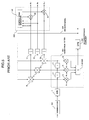
- Fig.4 is a block diagram of a conventional automatic equalizer as a first example of a prior art. A
reference numeral 1 is an A/D converter.Reference numerals T. Reference numerals 4 to 6 are multipliers.Reference numeral 7 is an adder, 8 to 10 are correlators, 11 to 13 are integrators, 101 is a demodulator, 201 is a transversal filter, and 301 is a decision feedback equalizer (DFE). - The adaptive matched filter of a
T space 3 tap type is composed of thetransversal filter 201, the correlators 8 to 10, and theintegrators 11 to 13. - The operation of the automatic equalizer of this type is hereinafter described.
- The
demodulator 101 demodulates a received signal, and a demodulated signal is sample-quantized by the A/D converter 1. The sample-quantized digital signal string output from the A/D converter 1 is input to thetransversal filter 201, then delayed by thedelay circuits transversal filter 201 and output signals of thedelay circuits multipliers 4 to 6 where they are multiplied by tap coefficients A₋₁, A₀, and A₊₁, respectively. Outputs of themultipliers 4 to 6 are added through theadder 7. The output of theadder 7 is input to the DFE 301 where the intersymbol interference is equalized and decided. - A
decision signal 104 output from the DFE 301 is input to the correlators 8 to 10 where thedecision signal 104, the input signal of thetransversal filter 201 and output signals of thedelay circuits integrators 11 to 13 to define new tap coefficients A₋₁, A₀, and A₊₁, of thetransversal filter 201. - Convolution of those tap coefficients and received signals provides outputs of the adaptive matched filter (AMF) corresponding to the impulse response on the propagation path. Fig.6 shows waveforms of the output response in case of ρ>1. Fig.7 shows waveforms of the output response in case of ρ<1.
- The adaptive matched filter (AMF) serves to disperse the interference wave component due to frequency selective fading generated on the propagation path ahead and behind the main wave component, respectively as shown by Figs. 6 and 7.
- In case of ρ>1, i.e., the amplitude of the delayed wave is larger than that of the preceding wave, the AMF enables the preceding wave as the interference component to be dispersed ahead and behind the main wave. With this mechanism, the interference wave component preceding the main wave that is difficult to be equalized by the DFE located behind the AMF is converted into that behind the main wave, thus the equalization characteristic of this case can be improved.
- In case of ρ<1, however, the construction of the first example of the conventional automatic equalizer generates the interference wave component preceding the main wave as Fig.7 shows. Accordingly the equalization characteristic is degraded compared with the construction using the DFE unity only.
- Aiming at overcoming the aforementioned degradation, another type of the equalizer has been proposed in Japanese Patent Laid-Open No. 77106(1992). It is so constructed to operate the DFE unity only by suspending the AMF in case of ρ<1. While in case of ρ >1, the AMF and DFE are operated together. The operation of the AMF is suspended by fixing the tap coefficients of Fig.5 to initial values A₀=1, A₋₁=A₊₁=0 (The DFE unit only). This mechanism is realized by adding a control circuit for controlling those tap coefficients to the construction shown by Fig.4.
- Fig.5 is a block diagram of the second example of the conventional automatic equalizer. The same construction items as those shown by Fig.4 have the same reference numerals, thus omitting their explanations.
- Referring to Fig.5,
reference numerals - The
control signal generator 32 monitors outputs of theintegrators 11 to 13 which represent impulse responses on the propagation path to determine the status thereof. - If the propagation path status is determined as ρ >1, the
control signal generator 32outputs 1 to themultipliers 15 and 16, respectively to operate the AMF and DFE in the same manner as described in the first example. While if determined as ρ<1, it gradually decreases the value output to themultipliers - In this case, the AMF generates outputs without diverging the interference wave as Figs. 8 and 9 show.
- Adding the
control circuit 402 provides higher equalization characteristic with the automatic equalizer compared with the first example on the propagation path status in case of both ρ>1 and ρ<1. - When using this equalizer as the second example, in case the propagation path is determined as ρ<1 and the interference wave component becomes excessively large, it no longer performs its equalization characteristic appropriately, which causes output signals to be dispersed. In this case, the closer ρ approaches the
value 1, the more difficult it becomes to perform pull-in operation, i.e., converging the location of output signals of the equalizer. - If the propagation path is determined as ρ<1, the AMF is reset (suspended) and DFE unity is only operated. So the interference wave component is not dispersed by the AMF, requiring some DFE taps to have substantially a great value.
- When the propagation path status is in the vicinity of ρ=1, it may be further difficult to perform pull-in operation due to additional AMF reset control.
- In the first example of the prior art of Fig.4, the AMF disperses the interference wave component to require no great value of tap coefficient for the respective DFE taps even if the communication path status is in the vicinity of ρ=1, resulting in easy pull-in operation.
- In this case, however, as aforementioned, the equalization characteristic is degraded during pull-in status.
- It is an object of the present invention to provide an automatic equalizer with excellent equalization characteristic to improve the pull-in operation of the control loop under fading for providing the solution to the aforementioned problem.
- The aforementioned object is realized by providing an automatic equalizer comprising a demodulator for outputting a detection signal which indicates synchronous status as well as demodulating analog base band signals from received signals, an A/D converter for outputting a first digital signal string by sample-quantizing the analog base band signals, an adaptive matched filter for outputting a second digital signal string by converting the first digital signal string, a decision feedback equalizer for outputting a decision signal by equalizing intersymbol interferences in the second digital signal string, a correlator for correlating the decision signal with a signal on each tap of the adaptive matched filter, an integrator for averaging outputs of the correlator, and a control means for outputting each tap coefficient of the adaptive matched filter derived from multiplying an output of the integrator by a weighting coefficient based on the detection signal.
- The principle of the automatic equalizer of the present invention is described below. When the propagation path status is determined as ρ>1, the interference wave precedes the main wave, so the tap in the plus side (hereinafter referred to as "plus tap(s)") (more remotely from the input than the center tap) is correlated. At this time the tap in the minus side (hereinafter referred to as "minus tap(s)") (closer to the input than the center tap) is hardly correlated.
- When the propagation path status is determined as ρ<1, the interference wave is behind the main wave, so the minus tap among the AMF taps is correlated to increase the value of its tap coefficient. At this time the plus tap is hardly correlated.
- The operation of the AMF minus tap is reset when the control is loop pulled-in, i.e., the demodulator is in synchronous status. In this case, the interference wave component is symmetrically dispersed through the AMF plus tap in case of ρ>1. While in case of ρ<1, the AMF outputs almost the same signals as input signals.
- Similar to the case shown by Figs. 8 and 9, therefore, in case of ρ>1, the AMF improves the equalization characteristic, while in case of ρ<1, the same equalization characteristic as that of the DFE unity can be obtained.
- When the control loop is divergent, i.e., the modulator is in asynchronous status, all taps of the AMF are enabled to improve the pull-in property. Once the control loop has been pulled-in, the AMF minus tap coefficient is gradually decreased at a rate lower than the tracking rate of DFE control. The operation of the AMF is, thus, suspended to enter into normal equalization.
- The AMF minus tap becomes active only in the repulling-in process after the control loop has diverged. Then the AMF operation is suspended so as to facilitate pull-in operation for the automatic equalizer.
- This and other objects, features and advantages of the present invention will become more apparent upon a reading of the following detailed description and drawings, in which:
- Fig.1 is a block diagram of an embodiment of an automatic equalizer of the present invention;
- Fig.2 is a block diagram of a weighting coefficient control circuit;
- Fig.3 is an explanatory view of an operation of the weighting coefficient control circuit;
- Fig.4 is a block diagram of a first example of a prior art;
- Fig.5 is a block diagram of a second example of a prior art;
- Fig.6 is an explanatory view of an operation of an adaptive matched filter;
- Fig.7 is an explanatory view of an operation of the adaptive matched filter;
- Fig.8 is an explanatory view of an operation of the adaptive matched filter; and
- Fig.9 is an explanatory view of an operation of the adaptive matched filter.
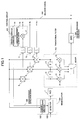
- Fig.1 is a block diagram of an embodiment of the present invention. In Fig.1, the same construction items as those shown by Fig.4 have the same reference numerals, thus omitting their explanations. As Fig.1 shows, taps of a
transversal filter 201 are divided into a center tap A₀, minus taps A₋₁ located at signal input side, and plus taps A₊₁ located at signal output side. - A
demodulator 101 in Fig.1 comprises acarrier reproduction section 102 and adetector 103. - The
carrier reproduction section 102 reproduces the carrier by means of decision signals and error signals output from theDFE 301. It also outputs adetection signal 105 indicating synchronous status of carrier reproduction. More specifically when the carrier reproduction is in synchronous status, theoutput detection signal 105 indicates synchronous status. On the contrary when it is in asynchronous due to divergence in the carrier reproduction loop, thedetection signal 105 indicates the asynchronous status. - The
detector 103 demodulates the reproduced carrier output from thecarrier reproduction section 102 and output an analog base band signal to A/D converter 1. - A
control circuit 401 comprises aweighting coefficient generator 14, a weightingcoefficient control circuit 16, and amultiplier 17. - The
detection signal 105 output from thecarrier reproduction section 102 is input to theweighting coefficient generator 14. In case thedetection signal 105 indicates the synchronous status, it outputs theweighting coefficient 0. While in case thedetection signal 105 indicates asynchronous status, it outputs theweighting coefficient 1. - The weighting
coefficient control circuit 16 controls weighting coefficients output from theweighting coefficient generator 14 based on thedetection signal 105. - Fig.2 is a block diagram of the weighting
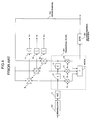
coefficient control circuit 16. - Referring to Fig.2, a
reference numeral 21 is a change amount set circuit, 22 and 23 are selectors, 24 is a flip-flop, 25 is a subtracter, and 26 is a detector. - In the change amount set
circuit 21, change amount of the weighting coefficient is so set that the rate at which the weighting coefficient decreases from 1 to 0 is lower than the tracking rate of theDFE 301 control accompanied with the change in the status of the demodulator 101 from asynchronous to synchronous. - The
selector 22 receives a weighting coefficient output from theweighting coefficient generator 14 and a feedback value from thesubtracter 25. In case thedetection signal 105 indicates the synchronous status, the feedback value from thesubtracter 25 is selected to be output. In case it indicates asynchronous status, the weighting coefficient output from theweighting coefficient generator 14 is selected to be output. - The
selector 23 receives a change amount output from the change amount setcircuit 21 and avalue 0. In case thedetection signal 105 indicates synchronous status, the change amount output from the change amount setcircuit 21 is selected to be output. In case it indicates asynchronous status, thevalue 0 is selected to be output. - The flip-
flop 24 retains the value output from theselector 22, and outputs it upon receiving the next value. - The
subtracter 25 subtracts an output value of theselector 22 from that of the flip-flop 24. - The
detector 26 monitors the feedback value from thesubtracter 25. In case the feedback value is 0, it outputs a detection signal to theselector 22 to cause theweighting coefficient generator 14 to output the weighting coefficient and outputs a detection signal to theselector 23 to output thevalue 0. - The
multiplier 17 multiplies an output of thecorrelator 11 by the output of the weightingcoefficient control circuit 16 and output a result as a coefficient of the tap A₋₁. - An operation of the above-constructed automatic equalizer is explained.
- Assuming that the demodulator causes synchronization step out due to divergence of the carrier reproduction loop, the
carrier reproduction section 102 outputs adetection signal 105 indicating asynchronous status to theweighting coefficient generator 14 and the weightingcoefficient control circuit 16. - Upon receiving the
detection signal 105, theweighting coefficient generator 14 outputs theweighting coefficient 1. - While, the
selector 22 that receives thedetection signal 105 selects theweighting coefficient 1 output from theweighting coefficient generator 14 to be output. Theselector 23 selects 0 to be output to thesubtracter 25. - Then the
subtracter 25subtracts 0 from theweighting coefficient 1 that has been input via the flip-flop 24. It outputs theresultant weighting coefficient 1. - The
multiplier 17 multiplies theweighting coefficient 1 by an output of thecorrelator 11. The resultant value is output as the coefficient of the tap A₋₁. - When the
detection signal 105 indicates asynchronous status, theweighting coefficient 1 is output to make the tap A₋₁ of the AMF active. - Next, assuming that the demodulator currently in asynchronous status changes into the synchronous status, the
carrier reproduction section 102 outputs adetection signal 105 indicating synchronous status to theweighting coefficient generator 14 and the weightingcoefficient control circuit 16. - Upon receiving the
detection signal 105, theweighting coefficient generator 14 outputs theweighting coefficient 0. - While, the
selector 22 that has received thedetection signal 105 selects the feedback value from the subtracter 25 (Since the flip-flop 24 retains thevalue 1, the initial value is derived form subtracting the change amount from 1, i.e., 1 - change amount.), and outputs it. - The
selector 23 selects the change amount output from the change amount setcircuit 21 to be output to thesubtracter 25. - The
subtracter 25 subtracts the change amount from the input value via the flip-flop 24. That is, the output value decreases by the change amount at every subtraction. The rate required for the change is lower than the tracking rate of theDFE 301 control. Fig.3 shows how this change has been done. - The
multiplier 17 multiplies the output value of thecorrelator 11 by the weighting coefficient to be output as the coefficient of the tap A₋₁. When the feedback value from thesubtracter 25reaches 0, thedetector 26 outputs detection signals to theselectors selector 22 selects the output of theweighting coefficient generator 14, i.e., 1, and theselector 23 selects 0 to be output, respectively. - Then, the
subtracter 25 subtracts thevalue 0 that is output by theweighting coefficient generator 14 from thevalue 0 that is output by theselector 23, i.e. "0". - When indication of the
detection signal 105 changes into synchronous status from asynchronous status, the weighting coefficient is decreased from 1 to 0 at a rate lower than the tracking rate of theDFE 301 control, the operation of tap A₋₁ of the AMF is stoped. - With the above mechanism, the equalization characteristic is improved with the effect of the AMF tap A₊₁ in case of ρ>1. In addition almost the same equalization characteristic as that of the DFE unity can be obtained in case of ρ<1.
- When the control loop is in divergence, pull-in property is improved by operating all taps of the AMF. Once the control loop has been pulled-in, the tap coefficient of the AMF tap A₋₁ is gradually decreased at a rate lower than the tracking rate of the DFE control. It is further decreased to 0, i.e., the AMF is suspended, thus entering normal equalization operation.
- The above explanation relates to a transversal filter of 3 tap type as a simple example. However, it is obvious to be able to form a transversal filter using a plurality of taps. That is, the present invention is realized by controlling all the minus taps to the center tap using an asynchronous detection signal from the demodulator in the same manner as described with respect to this embodiment.
- According to the present invention as described above, all taps of the AMF are operated while the control loop is pulled-in. Once the control loop has been pulled-in, a tap coefficient for the minus tap of the AMF is gradually decreased at a rate lower than the tracking rate of the DFE control to stop operation of the AMF. The above construction realizes the automatic equalizer with excellent equalization characteristic and improved pull-in property for the control loop under fading on the propagation path status either in ρ>1 or ρ<1.
Claims (14)
- An automatic equalizer comprising: a demodulator (101) for outputting a detection signal which indicates synchronous status as well as demodulating analog base band signals from received signals; an analog to digital converter (1) for converting said analog base band signals to a first digital signal string by sample-quantizing said analog base band signals; an adaptive matched filter (201) for converting said first digital signal string to a second digital signal string; a decision feedback equalizer(301) for equalizing intersymbol interferences in said second digital signal string and outputting a decision signal as an equalized result; a plurality of correlators (8 to 10), and each of said correlators for correlating said decision signal with a signal on each tap of said adaptive matched filter, and a plurality of integrators (11 to 13), each of said integrators for averaging outputs of said correlator, an automatic equalizer characterized in comprising
a control means (401) for multiplying an output of said integrator by a weighting coefficient based on said detection signal and outputting a result for each tap coefficient of said adaptive matched filter. - The automatic equalizer of claim 1, characterized in that said adaptive matched filter (201) comprises a transversal filter.
- The automatic equalizer of claim 1 or 2, wherein said control means (401) is provided for:
multiplying outputs of said integrators corresponding to minus taps locating in an input side from a center tap of said adaptive matched filter by a weighting coefficient 0 when said detection signal indicates synchronous status; and
multiplying outputs of said integrators corresponding to said minus taps by a weighting coefficient 1 when said detection signal indicates asynchronous status. - The automatic equalizer of claim 3, characterized in that said control means (401) comprises:
a plurality of multipliers (17), each of said multipliers for multiplying outputs of said integrators corresponding to said minus taps by said weighting coefficient; and
a weighting coefficient generator (14) for outputting a weighting coefficient 0 to said multipliers when said detection signal indicates synchronous status and for outputting a weighting coefficient 1 to said multipliers when said detection signal indicates asynchronous status. - The automatic equalizer of claim 3 or 4, wherein said control means (401) is provided for gradually decreasing said weighting coefficient from 1 to 0 at a rate lower than the tracking rate of said decision feedback equalizer when indication of said detection signal changes to synchronous status from asynchronous status.
- The automatic equalizer of claim 5, characterized in that said control means (401) comprises a first selector (22) and a second selector (23), each of them for switching output based on said detection signal, a flip-flop (24) connected with said first selector, and a subtracter (25) for subtracting an output of said second selector from an output of said flip-flop, the automatic equalizer characterized in taht;
said first selector (22) inputs an output of said subtracter and an output of said weighting coefficient generator, selects an output of said weighting coefficient generator when said detection signal indicates synchronous status, and selects an output of said subtracter when said detection signal indicates asynchronous status; and
said second selector (23) inputs a tap coefficient change amount and 0, selects 0 when said detection signal indicates synchronous status, and selects said tap coefficient change amount when said detection signal indicates asynchronous status. - The automatic equalizer of claim 6, characterized in that said tap coefficient change amount can be set optionally.
- An automatic equalizer comprising: a demodulator (101) for outputting a detection signal which indicates synchronous status as well as demodulating analog base band signals from received signals; an analog to digital converter (1) for converting said analog base band signals to a first digital signal string by sample-quantizing said analog base band signals; an adaptive matched filter (201) comprising a transversal filter having a center tap, a plurality of minus taps locating in an input side from said center tap and a plurality of plus taps locating in an output side from said center tap, said adaptive matched filter for converting said first digital signal string to a second digital signal string; a decision feedback equalizer (301) for equalizing intersymbol interferences in said second digital signal string and outputting a decision signal as an equalized result; a plurality of correlators (8 to 10), each of said correlators for correlating said decision signal with a signal on each tap of said adaptive matched filter; and a plurality of integrators (11 to 13), each of said integrators for averaging outputs of said correlator, an automatic equalizer characterized in comprising
a control means (401) for multiplying outputs of said integrators corresponding to said minus taps by a weighting coefficient 0 when said detection signal indicates synchronous status, multiplying outputs of said integrators corresponding to said minus taps by a weighting coefficient 1 when said detection signal indicates asynchronous status, and gradually decreasing said weighting coefficient from 1 to 0 at a rate lower than the tracking rate of said decision feedback equalizer when indication of said detection signal changes to synchronous status from asynchronous status. - The automatic equalizer of claim 8, characterized in that said control means (401) comprises:
a weighting coefficient generator (14) for inputting said detection signal, outputting a weighting coefficient 0 when said detection signal indicates synchronous status and outputting a weighting coefficient 1 when said detection signal indicates asynchronous status;
a first selector (22) and a second selector (23), each of them for switching an output based on said detection signal;
a flip-flop (24) connected with said first selector;
a subtracter (25) for subtracting an output of said second selector from an output of said flip-flop; and
a plurality of multipliers (17), each of said multipliers for multiplying outputs of said integrators corresponding to said minus taps by an output of said subtracter, characterized in that:
said first selector (22) inputs an output of said subtracter and an output of said weighting coefficient generator, selects an output of said weighting coefficient generator when said detection signal indicates synchronous status, and selects an output of said subtracter when said detection signal indicates asynchronous status; and
said second selector (23) inputs a tap coefficient change amount and 0, selects 0 when said detection signal indicates synchronous status, and selects said tap coefficient change amount when said detection signal indicates asynchronous status. - The automatic equalizer of claim 9, characterized in that said tap coefficient change amount can be set optionally.
- A method for controlling tap coefficients of an adaptive matched filter for demodulating analog base band signals from a received signal using a demodulator, dispersing interference wave components of said analog base band signals using an adaptive matched filter and wave-equalizing the result using a decision feedback equalizer, a method for controlling tap coefficients of an adaptive matched filtercharacterized in taht:(a) step of detecting a synchronous status of said demodulator; and(b) step of suspending operations of minus taps locating in an input side from a center tap when said demodulator is synchronized, and activating operations of said minus taps when said demodulator is not synchronized.
- The method for controlling tap coefficients of claim 11, characterized in that tap coefficients of said minus taps are gradually decreased at a rate lower than the tracking rate of said decision feedback equalizer in said (b) step when status of said demodulator changes to synchronous status from asynchronous status.
- A method for controlling tap coefficients of an automatic equalizer characterized in comprising:(a) step of demodulating analog base band signals from received signals using a demodulator and detecting synchronous status of carrier reproduction;(b) step of converting said analog base band signal string to a first digital signal string by sample-quantizing said analog base band signals using an analog to digital converter;(c) step of converting said first digital signal string to a second digital signal string by converting said first digital signal string using an adaptive matched filter;(d) step of outputting a decision signal by equalizing intersymbol interferences in said second digital signal string using a decision feedback equalizer;(e) step of correlating said decision signal with a signal on each tap of said adaptive matched filter using a plurality of correlators;(f) step of averaging outputs of said correlator using a plurality of integrators; and(g) step of multiplying outputs of said integrators corresponding to minus taps locating in an input side from a center tap of said adaptive matched filter by a weighting coefficient 0 when said carrier reproduction is in synchronous status, and multiplying outputs of said integrators corresponding to said minus taps by a weighting coefficient 1 when said carrier reproduction is in asynchronous status.
- The method for controlling tap coefficients of an automatic equalizer of claim 13, characterized in that said weighting coefficient is gradually decreased from 1 to 0 at a rate lower than the tracking rate of said decision feedback equalizer is said (g) step when status of said carrier reproduction changes to synchronous status from asynchronous status.
Applications Claiming Priority (3)
| Application Number | Priority Date | Filing Date | Title |
|---|---|---|---|
| JP5758994 | 1994-03-28 | ||
| JP57589/94 | 1994-03-28 | ||
| JP5758994 | 1994-03-28 |
Publications (3)
| Publication Number | Publication Date |
|---|---|
| EP0675608A2 true EP0675608A2 (en) | 1995-10-04 |
| EP0675608A3 EP0675608A3 (en) | 2000-09-13 |
| EP0675608B1 EP0675608B1 (en) | 2004-12-01 |
Family
ID=13060042
Family Applications (1)
| Application Number | Title | Priority Date | Filing Date |
|---|---|---|---|
| EP95104557A Expired - Lifetime EP0675608B1 (en) | 1994-03-28 | 1995-03-28 | Method and apparatus for controlling tap coefficients of an adaptive matched filter in an automatic equaliser |
Country Status (3)
| Country | Link |
|---|---|
| US (1) | US5668832A (en) |
| EP (1) | EP0675608B1 (en) |
| DE (1) | DE69533816T2 (en) |
Cited By (4)
| Publication number | Priority date | Publication date | Assignee | Title |
|---|---|---|---|---|
| WO2006036663A1 (en) * | 2004-09-27 | 2006-04-06 | Intel Corporation | Feed forward equalizer |
| WO2006036662A2 (en) * | 2004-09-27 | 2006-04-06 | Intel Corporation | Feed forward equalizer for a communication system |
| GB2422989A (en) * | 2005-02-03 | 2006-08-09 | Agilent Technologies Inc | Correlating a received data signal with a time delayed version of the signal to obtain a measurement of inter-symbol interference |
| WO2008115702A1 (en) * | 2007-03-21 | 2008-09-25 | Freescale Semiconductor Inc. | Adaptive equalizer for communication channels |
Families Citing this family (4)
| Publication number | Priority date | Publication date | Assignee | Title |
|---|---|---|---|---|
| US6067655A (en) * | 1997-08-28 | 2000-05-23 | Stmicroelectronics, N.V. | Burst error limiting symbol detector system |
| IL133451A0 (en) * | 1999-12-10 | 2001-04-30 | Dspc Tech Ltd | Programmable convolver |
| TW480832B (en) * | 1999-12-20 | 2002-03-21 | Koninkl Philips Electronics Nv | An arrangement for receiving a digital signal from a transmission medium |
| US8270457B2 (en) * | 2007-06-27 | 2012-09-18 | Qualcomm Atheros, Inc. | High sensitivity GPS receiver |
Citations (4)
| Publication number | Priority date | Publication date | Assignee | Title |
|---|---|---|---|---|
| JPS5992631A (en) * | 1982-11-19 | 1984-05-28 | Fujitsu Ltd | Tap weight coefficient control system |
| US4567599A (en) * | 1982-10-01 | 1986-01-28 | Nec Corporation | Automatic adaptive equalizer having improved reset function |
| JPH0477106A (en) * | 1990-07-17 | 1992-03-11 | Nec Corp | Adaptive receiver |
| EP0534489A2 (en) * | 1991-09-27 | 1993-03-31 | Nec Corporation | Fractional equaliser for use with a DFE |
Family Cites Families (6)
| Publication number | Priority date | Publication date | Assignee | Title |
|---|---|---|---|---|
| JP2616152B2 (en) * | 1990-06-15 | 1997-06-04 | 日本電気株式会社 | Automatic equalizer |
| JP3251023B2 (en) * | 1991-02-27 | 2002-01-28 | 日本電気株式会社 | Automatic equalizer |
| JP3169646B2 (en) * | 1991-09-25 | 2001-05-28 | 日本電気株式会社 | Cross polarization interference compensator |
| JPH05183456A (en) * | 1991-12-27 | 1993-07-23 | Nec Corp | Control signal generator |
| JPH0744473B2 (en) * | 1993-02-02 | 1995-05-15 | 日本電気株式会社 | Demodulation system |
| JPH0738560B2 (en) * | 1993-02-23 | 1995-04-26 | 日本電気株式会社 | Automatic equalizer |
-
1995
- 1995-03-28 EP EP95104557A patent/EP0675608B1/en not_active Expired - Lifetime
- 1995-03-28 US US08/411,537 patent/US5668832A/en not_active Expired - Lifetime
- 1995-03-28 DE DE69533816T patent/DE69533816T2/en not_active Expired - Lifetime
Patent Citations (4)
| Publication number | Priority date | Publication date | Assignee | Title |
|---|---|---|---|---|
| US4567599A (en) * | 1982-10-01 | 1986-01-28 | Nec Corporation | Automatic adaptive equalizer having improved reset function |
| JPS5992631A (en) * | 1982-11-19 | 1984-05-28 | Fujitsu Ltd | Tap weight coefficient control system |
| JPH0477106A (en) * | 1990-07-17 | 1992-03-11 | Nec Corp | Adaptive receiver |
| EP0534489A2 (en) * | 1991-09-27 | 1993-03-31 | Nec Corporation | Fractional equaliser for use with a DFE |
Non-Patent Citations (2)
| Title |
|---|
| PATENT ABSTRACTS OF JAPAN vol. 008, no. 206 (E-267), 20 September 1984 (1984-09-20) & JP 59 092631 A (FUJITSU KK), 28 May 1984 (1984-05-28) * |
| PATENT ABSTRACTS OF JAPAN vol. 016, no. 294 (E-1225), 29 June 1992 (1992-06-29) & JP 04 077106 A (NEC CORP), 11 March 1992 (1992-03-11) * |
Cited By (7)
| Publication number | Priority date | Publication date | Assignee | Title |
|---|---|---|---|---|
| WO2006036663A1 (en) * | 2004-09-27 | 2006-04-06 | Intel Corporation | Feed forward equalizer |
| WO2006036662A2 (en) * | 2004-09-27 | 2006-04-06 | Intel Corporation | Feed forward equalizer for a communication system |
| WO2006036662A3 (en) * | 2004-09-27 | 2006-07-13 | Intel Corp | Feed forward equalizer for a communication system |
| US7551667B2 (en) | 2004-09-27 | 2009-06-23 | Intel Corporation | Feed forward equalizer |
| US7738546B2 (en) | 2004-09-27 | 2010-06-15 | Intel Corporation | Feed forward equalizer for a communication system |
| GB2422989A (en) * | 2005-02-03 | 2006-08-09 | Agilent Technologies Inc | Correlating a received data signal with a time delayed version of the signal to obtain a measurement of inter-symbol interference |
| WO2008115702A1 (en) * | 2007-03-21 | 2008-09-25 | Freescale Semiconductor Inc. | Adaptive equalizer for communication channels |
Also Published As
| Publication number | Publication date |
|---|---|
| DE69533816D1 (en) | 2005-01-05 |
| EP0675608B1 (en) | 2004-12-01 |
| EP0675608A3 (en) | 2000-09-13 |
| US5668832A (en) | 1997-09-16 |
| DE69533816T2 (en) | 2005-04-21 |
Similar Documents
| Publication | Publication Date | Title |
|---|---|---|
| US5394110A (en) | Demodulation system having adaptive matched filter and decision feedback equalizer | |
| EP0755141B1 (en) | Adaptive decision feedback equalization for communication systems | |
| KR100283379B1 (en) | Parallel Multistage Interference Cancellation | |
| US5905946A (en) | Method for estimating a channel and a receiver | |
| US5388123A (en) | Data receiving system | |
| CA2079292C (en) | Fast response matched filter receiver with decision feedback equalizer | |
| EP0716513A1 (en) | Diversity receiver in which reception characteristics can be improved | |
| CA2109737A1 (en) | Compensation for multi-path interference using pilot symbols | |
| CA2076710C (en) | Channel impulse response estimator for a system having a rapidly fluctuating channel characteristic | |
| US5335359A (en) | Diversity receiver using matched filter and decision feedback equalizer | |
| JP3099831B2 (en) | Automatic equalizer | |
| US5668832A (en) | Automatic equalizer for removing inter-code interference with fading and method of controlling tap coefficients thereof | |
| JPH04271508A (en) | Automatic equalizer | |
| JP2616152B2 (en) | Automatic equalizer | |
| EP0235300B1 (en) | Radio data transmission system | |
| JP2611557B2 (en) | Decision feedback type automatic equalizer | |
| US20020027952A1 (en) | Method for automatic equalization for use in demodulating a digital multilevel modulation signal and automatic equalization circuit and receiver circuit using the method | |
| US5418816A (en) | Automatic equalizer | |
| JP2871519B2 (en) | Automatic equalizer | |
| JP3371256B2 (en) | Automatic equalizer | |
| JP2833587B2 (en) | Demodulator | |
| Ng et al. | Bandwidth-efficient pilot-symbol-aided technique for multipath-fading channels | |
| Henriksson | Decision-Directed Diversity Combiners--Principles and Simulation Results | |
| Guglielmi et al. | Joint clock recovery and baseband combining for the diversity radio channel | |
| JPH05218800A (en) | Automatic equalizer |
Legal Events
| Date | Code | Title | Description |
|---|---|---|---|
| PUAI | Public reference made under article 153(3) epc to a published international application that has entered the european phase |
Free format text: ORIGINAL CODE: 0009012 |
|
| AK | Designated contracting states |
Kind code of ref document: A2 Designated state(s): DE FR |
|
| PUAL | Search report despatched |
Free format text: ORIGINAL CODE: 0009013 |
|
| AK | Designated contracting states |
Kind code of ref document: A3 Designated state(s): DE FR |
|
| RIC1 | Information provided on ipc code assigned before grant |
Free format text: 7H 04B 7/005 A, 7H 04L 25/03 B |
|
| 17P | Request for examination filed |
Effective date: 20000809 |
|
| 17Q | First examination report despatched |
Effective date: 20030403 |
|
| GRAP | Despatch of communication of intention to grant a patent |
Free format text: ORIGINAL CODE: EPIDOSNIGR1 |
|
| GRAS | Grant fee paid |
Free format text: ORIGINAL CODE: EPIDOSNIGR3 |
|
| GRAA | (expected) grant |
Free format text: ORIGINAL CODE: 0009210 |
|
| AK | Designated contracting states |
Kind code of ref document: B1 Designated state(s): DE FR |
|
| REF | Corresponds to: |
Ref document number: 69533816 Country of ref document: DE Date of ref document: 20050105 Kind code of ref document: P |
|
| PLBE | No opposition filed within time limit |
Free format text: ORIGINAL CODE: 0009261 |
|
| STAA | Information on the status of an ep patent application or granted ep patent |
Free format text: STATUS: NO OPPOSITION FILED WITHIN TIME LIMIT |
|
| ET | Fr: translation filed | ||
| 26N | No opposition filed |
Effective date: 20050902 |
|
| PGFP | Annual fee paid to national office [announced via postgrant information from national office to epo] |
Ref country code: DE Payment date: 20130320 Year of fee payment: 19 Ref country code: FR Payment date: 20130325 Year of fee payment: 19 |
|
| REG | Reference to a national code |
Ref country code: DE Ref legal event code: R119 Ref document number: 69533816 Country of ref document: DE |
|
| REG | Reference to a national code |
Ref country code: FR Ref legal event code: ST Effective date: 20141128 |
|
| REG | Reference to a national code |
Ref country code: DE Ref legal event code: R119 Ref document number: 69533816 Country of ref document: DE Effective date: 20141001 |
|
| PG25 | Lapsed in a contracting state [announced via postgrant information from national office to epo] |
Ref country code: DE Free format text: LAPSE BECAUSE OF NON-PAYMENT OF DUE FEES Effective date: 20141001 Ref country code: FR Free format text: LAPSE BECAUSE OF NON-PAYMENT OF DUE FEES Effective date: 20140331 |