EP0675308A1 - Pipe collar - Google Patents
Pipe collar Download PDFInfo
- Publication number
- EP0675308A1 EP0675308A1 EP95810016A EP95810016A EP0675308A1 EP 0675308 A1 EP0675308 A1 EP 0675308A1 EP 95810016 A EP95810016 A EP 95810016A EP 95810016 A EP95810016 A EP 95810016A EP 0675308 A1 EP0675308 A1 EP 0675308A1
- Authority
- EP
- European Patent Office
- Prior art keywords
- wall part
- pipe sleeve
- hook
- circumference
- sleeve according
- Prior art date
- Legal status (The legal status is an assumption and is not a legal conclusion. Google has not performed a legal analysis and makes no representation as to the accuracy of the status listed.)
- Granted
Links
Images


Classifications
-
- F—MECHANICAL ENGINEERING; LIGHTING; HEATING; WEAPONS; BLASTING
- F16—ENGINEERING ELEMENTS AND UNITS; GENERAL MEASURES FOR PRODUCING AND MAINTAINING EFFECTIVE FUNCTIONING OF MACHINES OR INSTALLATIONS; THERMAL INSULATION IN GENERAL
- F16L—PIPES; JOINTS OR FITTINGS FOR PIPES; SUPPORTS FOR PIPES, CABLES OR PROTECTIVE TUBING; MEANS FOR THERMAL INSULATION IN GENERAL
- F16L5/00—Devices for use where pipes, cables or protective tubing pass through walls or partitions
- F16L5/02—Sealing
- F16L5/04—Sealing to form a firebreak device
Definitions
- the invention relates to a tubular sleeve with a wall part and at least one fastening part which projects radially in the region of at least one end face of the wall part.
- pipe sleeves which consist of a wall part and a fastening part which projects radially in the area of at least one end face of the wall part.
- the wall part is composed essentially of two half-shell-like elements which can be pivoted relative to one another.
- the fastening part consists of a flange which projects radially outwards in the end region from the wall part and extends around the entire circumference of the pipe sleeve.
- the flange has at least one through hole which serves to penetrate a fastening element which can be connected to a base in order to be able to fix the flange or the entire pipe sleeve to a base.
- the invention has for its object to provide a pipe sleeve that can be quickly and easily arranged on pipes that are installed in corners, close to walls, ceilings or floors.
- the object is achieved in that the fastening part is detachably connected to the wall part.
- the detachable connection of the fastening part and wall part makes it possible to first connect the wall part of the pipe sleeve to the pipe and then to fasten the fastening part in that area of the circumference of the wall part in which the fastening part does not meet the walls, ceilings or Soils come into contact.
- the wall part preferably has at least one tab protruding in the radial direction on the circumference.
- the clear cross section of the tab expediently runs parallel to the central longitudinal axis of the wall part.
- the tabs are expediently arranged at substantially the same intervals on the circumference.
- the diagonal arrangement of the fastening parts and the arrangement of the fastening parts at equal distances from one another is thus possible. In this way, the holding force of the fastening parts fixed on the substrate is distributed evenly over the circumference of the wall part.
- the fastening part preferably has a hook which extends essentially along a surface line of the wall part and can be inserted into the tab.
- the fastening part also has a clamping surface which extends essentially at right angles to the opening of the hook and has at least one passage opening which serves to push through a fastening element.
- the hook is expediently designed to be open toward the end face of the wall part.
- the distance between the side of the clamping surface facing the surface and the inner curved section of the hook essentially corresponds to the distance between the end face of the wall part which comes into contact with the surface of the surface and the mouth region of the flap.
- the hook is expediently designed as a spring clip.
- the hook according to the invention has an opening width that is slightly smaller than the material thickness of the wall part in the area of the tab. When the hook is inserted into the tab, the hook is slightly widened so that it is put under pretension and a frictional connection is made with the tab.
- Another way of preventing the fastening part from being lost from the wall part is to create a positive connection between the fastening part and the wall part.
- This is preferably achieved with a hook which has a latching element which can be connected to the tab.
- the hook can have at least one projection on the inside, which can move into a depression or passage opening arranged on the tab.
- the fixing of the wall part can serve several fastening parts.
- the tubular sleeve shown in FIG. 1 has a wall part 1 with two half-shell-like elements which can be pivoted against one another via a common pivot axis 6.
- the end regions of the wall part 1, which lie opposite the pivot axis 6, are formed by two radially projecting flanges 7, 8, which serve to brace the wall part 1.
- the bracing is carried out by means of at least one clamping screw 9 which protrude through corresponding openings in the flanges 7, 8.
- the wall part 1 consists of a sheet metal profile, which is folded several times in the circumferential direction to form an essentially circular shape.
- bent, lateral extensions extend in the direction of the central longitudinal axis of the pipe sleeve, which have corresponding material cutouts 14 in order to be able to give the wall part 1 a circular shape.
- the inward bent, lateral extensions of the wall part 1 allow the inclusion and guidance of an insert 11 with fire-retardant properties.
- the wall part 1 has a plurality of evenly distributed, essentially radially projecting tabs 3 on the circumference, which, in conjunction with at least one fastening part 2, serve to fix the pipe sleeve on the surface of a substrate U.
- the pipe sleeve shown encloses a pipe 10 which is laid in the corner of a building.
- the two fastening parts 2 cannot be arranged everywhere on the circumference of the wall parts 1. Due to the plurality of tabs 3 arranged on the circumference of the wall parts 1, the fastening parts 2 can nevertheless be brought as close as possible to the walls and fastened.
- the two fastening parts 2 lie essentially diagonally opposite one another. When fixing the wall part 1, several fastening parts 2 can be used for fastening the pipe sleeve.
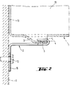
- the fastening part 2 shown in Fig. 2 has a hook 4 and a clamping surface 15, which is penetrated by a passage opening 12.
- a locking element 5 is arranged in the form of a projection, which with a corresponding, schematically illustrated depression or Passage opening in the tab of the holding part can enter into a positive connection.
- the width of the clamping surface 15 is larger than the width of the hook 4 which is matched to the clear cross section of the tab.
- the wall part 21 of the tubular sleeve shown in FIG. 3 also consists of two half-shell-like elements which are pivotally connected to one another via a pivot axis 29 and have radially projecting flanges 26, 27.
- the flanges 26, 27 are braced against one another with the aid of clamping screws 28.
- a plurality of tabs 22, 23 are arranged distributed along the circumference along two circumferential lines.
- the clear widths or cross sections L of the tabs 22, 23 have to each other, but are spaced from each other to enable the insertion of the hook of a fastening part, not shown.
- the tabs 22, 23 have through openings 24, 25, which can form-fit with locking elements on the hook of the fastening parts.
Abstract
Description
Die Erfindung betrifft eine Rohrmanschette mit Wandungsteil und wenigstens einem, im Bereich wenigstens einer Stirnseite des Wandungsteiles radial abragendem Befestigungsteil.The invention relates to a tubular sleeve with a wall part and at least one fastening part which projects radially in the region of at least one end face of the wall part.
Zur Abschottung von brennbaren Rohren sind Rohrmanschetten bekannt, die aus einem Wandungsteil und einem mit im Bereich wenigstens einer Stirnseite des Wandungsteiles radial abragendem Befestigungsteil bestehen. Das Wandungsteil setzt sich im wesentlichen aus zwei halbschalenartig ausgebildeten Elementen zusammen, die gegeneinander schwenkbar sind.For the sealing off of flammable pipes, pipe sleeves are known which consist of a wall part and a fastening part which projects radially in the area of at least one end face of the wall part. The wall part is composed essentially of two half-shell-like elements which can be pivoted relative to one another.
Das Befestigungsteil besteht aus einem Flansch, der im stirnseitigen Bereich vom Wandungsteil radial nach aussen abragt und sich um den gesamten Umfang der Rohrmanschette erstreckt. Der Flansch hat wenigstens eine Durchgangsbohrung, die der Durchsetzung eines mit einem Untergrund in Verbindung bringbaren Befestigungselementes dient, um den Flansch, bzw. die gesamte Rohrmanschette an einem Untergrund festlegen zu können. In der Rohrmanschette befindet sich eine Einlage mit brandhemmenden Eigenschaften.The fastening part consists of a flange which projects radially outwards in the end region from the wall part and extends around the entire circumference of the pipe sleeve. The flange has at least one through hole which serves to penetrate a fastening element which can be connected to a base in order to be able to fix the flange or the entire pipe sleeve to a base. There is an insert in the pipe sleeve with fire-retardant properties.
Die Verwendung dieser bekannten Rohrmanschette ist bei Rohren, die in Ecken, nahe an Wänden, Decken oder Böden angeordnet sind, nicht möglich, da der radiale Überstand des Flansches eine Montage der Rohrmanschette in der gewünschten Lage nicht zulässt.The use of this known pipe sleeve is not possible for pipes which are arranged in corners, close to walls, ceilings or floors, since the radial projection of the flange does not allow the pipe sleeve to be installed in the desired position.
Der Erfindung liegt die Aufgabe zugrunde, eine Rohrmanschette zu schaffen, die schnell und einfach an Rohren anordbar ist, die in Ecken, nahe an Wänden, Decken oder Böden verlegt sind.The invention has for its object to provide a pipe sleeve that can be quickly and easily arranged on pipes that are installed in corners, close to walls, ceilings or floors.
Erfindungsgemäss wird die Aufgabe dadurch gelöst, dass das Befestigungsteil mit dem Wandungsteil lösbar verbunden ist.According to the invention, the object is achieved in that the fastening part is detachably connected to the wall part.
Durch die lösbare Verbindung von Befestigungsteil und Wandungsteil ergibt sich die Möglichkeit, zuerst das Wandungsteil der Rohrmanschette mit dem Rohr in Verbindung zu bringen und anschliessend das Befestigungsteil in jenem Bereich des Umfanges des Wandungsteiles zu befestigen, in dem das Befestigungsteil nicht mit den Wänden, Decken oder Böden in Berührung gelangt.The detachable connection of the fastening part and wall part makes it possible to first connect the wall part of the pipe sleeve to the pipe and then to fasten the fastening part in that area of the circumference of the wall part in which the fastening part does not meet the walls, ceilings or Soils come into contact.
Für die lösbare Verbindung mit dem Befestigungsteil besitzt das Wandungsteil am Umfang vorzugsweise wenigstens eine in radialer Richtung abragende Lasche.For the releasable connection to the fastening part, the wall part preferably has at least one tab protruding in the radial direction on the circumference.
Damit die Festlegung der Rohrmanschette mit einer Stirnseite an der Oberfläche eines Untergrundes möglich ist, verläuft der lichte Querschnitt der Lasche zweckmässigerweise parallel zur Mittellängsachse des Wandungsteiles.So that it is possible to fix the pipe collar with an end face on the surface of a substrate, the clear cross section of the tab expediently runs parallel to the central longitudinal axis of the wall part.
Um eine Anbringung des Befestigungsteiles am Umfang des Wandungsteiles in Abhängigkeit des vorhandenen Platzes möglich zu machen, ist es von Vorteil, wenn mehrere Laschen entlang wenigstens einer Umfangslinie am Umfang des Wandungsteiles angeordnet sind.In order to make it possible to attach the fastening part to the circumference of the wall part depending on the available space, it is advantageous if a plurality of tabs are arranged along at least one circumferential line on the circumference of the wall part.
Aus herstellungs- und montagetechnischen Gründen sind die Laschen zweckmässigerweise unter im wesentlichen gleichen Abständen am Umfang angeordnet. Die diagonale Anordnung der Befestigungsteile und die Anordnung der Befestigungsteile in gleichen Abständen zueinander ist somit möglich. Die Haltekraft der am Untergrund festgelegten Befestigungsteile wird auf diese Weise gleichmässig am Umfang des Wandungsteiles verteilt.For manufacturing and assembly reasons, the tabs are expediently arranged at substantially the same intervals on the circumference. The diagonal arrangement of the fastening parts and the arrangement of the fastening parts at equal distances from one another is thus possible. In this way, the holding force of the fastening parts fixed on the substrate is distributed evenly over the circumference of the wall part.
Um ein Einhängen des Befestigungsteiles in dem lichten Querschnitt der Laschen des Wandungsteiles ermöglichen zu können, weist das Befestigungsteil vorzugsweise einen im wesentlichen entlang einer Mantellinie des Wandungsteiles verlaufenden, in die Lasche einführbaren Haken auf. Neben dem Haken hat das Befestigungsteil auch eine Klemmfläche, die im wesentlichen rechtwinklig zur Öffnung des Hakens verläuft und wenigstens eine Durchtrittsöffnung aufweist, die der Durchsetzung eines Befestigungselementes dient.In order to enable the fastening part to be hooked into the clear cross-section of the tabs of the wall part, the fastening part preferably has a hook which extends essentially along a surface line of the wall part and can be inserted into the tab. In addition to the hook, the fastening part also has a clamping surface which extends essentially at right angles to the opening of the hook and has at least one passage opening which serves to push through a fastening element.
Zweckmässigerweise ist der Haken zur Stirnseite des Wandungsteiles hin offen ausgebildet. Dabei entspricht der Abstand zwischen der zum Untergrund weisenden Seite der Klemmfläche und dem inneren Bogenabschnitt des Hakens im wesentlichen dem Abstand zwischen der an der Oberfläche des Untergrundes zur Anlage gelangenden Stirnseite des Wandungsteiles und dem Mündungsbereich der Lasche.The hook is expediently designed to be open toward the end face of the wall part. The distance between the side of the clamping surface facing the surface and the inner curved section of the hook essentially corresponds to the distance between the end face of the wall part which comes into contact with the surface of the surface and the mouth region of the flap.
Um eine gute Halterung des Hakens in der Lasche ermöglichen zu können, ist der Haken zweckmässigerweise als Federclip ausgebildet. Der erfindungsgemässe Haken besitzt eine Öffnungsweite, die geringfügig kleiner ist als die Materialstärke des Wandungsteiles im Bereich der Lasche. Beim Einschieben des Hakens in die Lasche wird der Haken geringfügig aufgeweitet, so dass er unter Vorspannung versetzt wird und zusammen mit der Lasche eine reibschlüssige Verbindung eingeht.In order to enable the hook to be held well in the tab, the hook is expediently designed as a spring clip. The hook according to the invention has an opening width that is slightly smaller than the material thickness of the wall part in the area of the tab. When the hook is inserted into the tab, the hook is slightly widened so that it is put under pretension and a frictional connection is made with the tab.
Eine weitere Möglichkeit, die Verlierbarkeit des Befestigungsteiles von dem Wandungsteil verhindern zu können, besteht darin, eine formschlüssige Verbindung zwischen dem Befestigungsteil und dem Wandungsteil zu schaffen. Vorzugsweise wird dies mit einem Haken erreicht, der ein mit der Lasche in Verbindung bringbares Rastelement aufweist. Als Rastelement kann der Haken an der Innenseite wenigstens einen Vorsprung aufweisen, der in eine entsprechend an der Lasche angeordnete Vertiefung bzw. Durchtrittsöffnung rücken kann.Another way of preventing the fastening part from being lost from the wall part is to create a positive connection between the fastening part and the wall part. This is preferably achieved with a hook which has a latching element which can be connected to the tab. As a latching element, the hook can have at least one projection on the inside, which can move into a depression or passage opening arranged on the tab.
Der Festlegung des Wandungsteiles können mehrere Befestigungsteile dienen.The fixing of the wall part can serve several fastening parts.
Die Erfindung wird anhand von Zeichnungen, die zwei Ausführungsbeispiele wiedergeben, näher erläutert. Es zeigen:
- Fig. 1
- eine erfindungsgemässe Rohrmanschette im festgelegten Zustand;
- Fig. 2
- ein Befestigungsteil für die Befestigung einer Rohrmanschette gemäss Fig. 1;
- Fig. 3
- eine weitere erfindungsgemässe Rohrmanschette mit mehreren, entlang zweier Umfangslinien am Umfang des Wandungsteiles angeordneten Laschen.
- Fig. 1
- a pipe sleeve according to the invention in the defined state;
- Fig. 2
- a fastening part for fastening a pipe sleeve according to FIG. 1;
- Fig. 3
- a further pipe sleeve according to the invention with a plurality of tabs arranged along two circumferential lines on the circumference of the wall part.
Die in Fig. 1 dargestellte Rohrmanschette weist ein Wandungsteil 1 mit zwei halbschalenartig ausgebildeten Elementen auf, die über eine gemeinsame Schwenkachse 6 gegeneinander schwenkbar sind. Die Endbereiche des Wandungsteiles 1, die der Schwenkachse 6 gegenüberliegen, sind gebildet von zwei radial abragenden Flanschen 7, 8, die dem Verspannen des Wandungsteiles 1 dienen. Die Verspannung erfolgt mittels wenigstens einer Klemmschraube 9, die durch entsprechende Durchtrittsöffnungen der Flansche 7, 8 hindurchragen.The tubular sleeve shown in FIG. 1 has a wall part 1 with two half-shell-like elements which can be pivoted against one another via a common pivot axis 6. The end regions of the wall part 1, which lie opposite the pivot axis 6, are formed by two radially projecting
Das Wandungsteil 1 besteht aus einem Blechprofil, das in Umfangsrichtung mehrmals abgekantet ist, um eine im wesentlichen kreisrunde Form zu bilden. An den Stirnseiten 13 des Wandungsteiles 1 erstrecken sich umgebogene, seitliche Verlängerungen in Richtung Mittellängsachse der Rohrmanschette, die entsprechende Materialaussparungen 14 aufweisen, um dem Wandungsteil 1 eine kreisrunde Form geben zu können. Die nach innen abgebogenen, seitlichen Verlängerungen des Wandungsteiles 1 gestatten die Aufnahme und die Führung einer Einlage 11 mit brandhemmenden Eigenschaften.The wall part 1 consists of a sheet metal profile, which is folded several times in the circumferential direction to form an essentially circular shape. At the end faces 13 of the wall part 1, bent, lateral extensions extend in the direction of the central longitudinal axis of the pipe sleeve, which have corresponding material cutouts 14 in order to be able to give the wall part 1 a circular shape. The inward bent, lateral extensions of the wall part 1 allow the inclusion and guidance of an
Das Wandungsteil 1 besitzt am Umfang mehrere gleichmässig verteilt angeordnete, im wesentlichen radial abstehende Laschen 3, die in Verbindung mit wenigstens einem Befestigungsteil 2 der Festlegung der Rohrmanschette an der Oberfläche eines Untergrundes U dienen.The wall part 1 has a plurality of evenly distributed, essentially radially projecting
Die dargestellte Rohrmanschette umschliesst ein Rohr 10, welches in der Ecke eines Bauwerkes verlegt ist. Die beiden Befestigungsteile 2 können nicht überall am Umfang der Wandungsteile 1 angeordnet werden. Aufgrund der mehreren am Umfang der Wandungsteile 1 angeordneten Laschen 3 können die Befestigungsteile 2 trotzdem so nahe wie möglich an die Wände herangeführt und befestigt werden. Die beiden Befestigungsteile 2 liegen sich im wesentlichen diagonal gegenüber. Bei der Festlegung des Wandungsteiles 1 können mehrere Befestigungsteile 2 für die Befestigung der Rohrmanschette verwendet werden.The pipe sleeve shown encloses a
Das in Fig. 2 dargestellte Befestigungsteil 2 besitzt einen Haken 4 und eine Klemmfläche 15, die durchsetzt ist von einer Durchtrittsöffnung 12. An der Innenseite des Hakens 4 ist ein Rastelement 5 in Form eines Vorsprunges angeordnet, das mit einer entsprechenden, schematisch dargestellten Vertiefung oder Durchtrittsöffnung in der Lasche des Halteteiles einen Formschluss eingehen kann.The fastening
Um eine gute Festlegung des Befestigungsteiles 2 am Untergrund U erreichen zu können, ist die Breite der Klemmfläche 15 grösser ausgebildet als die auf den lichten Querschnitt der Lasche abgestimmte Breite des Hakens 4.In order to be able to achieve a good fixing of the fastening
Das Wandungsteil 21 der in Fig. 3 dargestellten Rohrmanschette besteht ebenfalls aus zwei halbschalenartig ausgebildeten Elementen, die über eine Schwenkachse 29 schwenkbar miteinander verbunden sind und radial abstehende Flansche 26, 27 aufweisen. Die Flansche 26, 27 werden gegeneinander mit Hilfe von Klemmschrauben 28 verspannt. Entlang zweier Umfangslinien sind am Umfang verteilt mehrere Laschen 22, 23 angeordnet. Die lichten Weiten bzw. Querschnitte L der Laschen 22, 23 weisen dabei zueinander, sind aber voneinander beabstandet, um das Einführen des Hakens eines nicht dargestellten Befestigungsteiles zu ermöglichen. Die Laschen 22, 23 weisen Durchtrittsöffnungen 24, 25 auf, die mit Rastelementen am Haken der Befestigungsteile einen Formschluss eingehen können.The
Claims (9)
Applications Claiming Priority (2)
| Application Number | Priority Date | Filing Date | Title |
|---|---|---|---|
| DE4411220A DE4411220A1 (en) | 1994-03-31 | 1994-03-31 | Pipe sleeve |
| DE4411220 | 1994-03-31 |
Publications (2)
| Publication Number | Publication Date |
|---|---|
| EP0675308A1 true EP0675308A1 (en) | 1995-10-04 |
| EP0675308B1 EP0675308B1 (en) | 1998-04-08 |
Family
ID=6514331
Family Applications (1)
| Application Number | Title | Priority Date | Filing Date |
|---|---|---|---|
| EP95810016A Expired - Lifetime EP0675308B1 (en) | 1994-03-31 | 1995-01-10 | Pipe collar |
Country Status (8)
| Country | Link |
|---|---|
| US (1) | US5586739A (en) |
| EP (1) | EP0675308B1 (en) |
| JP (1) | JP3574215B2 (en) |
| AT (1) | ATE164930T1 (en) |
| DE (2) | DE4411220A1 (en) |
| ES (1) | ES2114288T3 (en) |
| FI (1) | FI106404B (en) |
| NO (1) | NO951244L (en) |
Cited By (4)
| Publication number | Priority date | Publication date | Assignee | Title |
|---|---|---|---|---|
| DE19852120A1 (en) * | 1998-08-19 | 2000-03-02 | Friatec Ag | Fire protection device |
| DE102015121031A1 (en) | 2014-12-03 | 2016-06-09 | Uta Kamleithner | Fire protection system |
| US9586066B2 (en) | 2012-10-11 | 2017-03-07 | Hilti Aktiengesellschaft | Fire protection collar |
| DE102021204139A1 (en) | 2021-04-26 | 2022-10-27 | James Hardie Europe Gmbh | Pipe collar, fire protection collar with such a pipe collar, ceiling duct, ceiling with such a ceiling duct and method for installing a ceiling duct |
Families Citing this family (16)
| Publication number | Priority date | Publication date | Assignee | Title |
|---|---|---|---|---|
| TW308613B (en) * | 1996-08-19 | 1997-06-21 | Jyi-Shyang Wang | Manufacturing method and device for carbon fabric absorbent |
| DE19840136A1 (en) * | 1998-09-03 | 2000-03-09 | Volkswagen Ag | Bracket and bracket for rigid cables in a vehicle |
| AUPQ024099A0 (en) | 1999-05-07 | 1999-06-03 | Promat Fyreguard Pty Ltd | Service shut off device |
| US20080035803A1 (en) * | 2006-08-03 | 2008-02-14 | Charles Ingalls | Self-leveling roof utility bucket with second pivotable bottom |
| NL2004318C2 (en) | 2010-03-01 | 2011-09-05 | Walraven Holding Bv J Van | FIRESTOP COLLAR. |
| CA2786194C (en) * | 2011-09-16 | 2019-01-15 | Hilti Aktiengesellschaft | Fire-prevention sleeve, use of the fire-prevention sleeve, method for installing a fire-prevention sleeve, and ceiling passage |
| DE102011089531A1 (en) * | 2011-12-22 | 2013-06-27 | Hilti Aktiengesellschaft | Fire protection sleeve |
| US8991774B2 (en) * | 2011-12-22 | 2015-03-31 | Panduit Corp. | Cable tie mount |
| EP3088784A1 (en) * | 2015-04-27 | 2016-11-02 | Hilti Aktiengesellschaft | Flame retardant sleeve |
| EP3088783A1 (en) | 2015-04-27 | 2016-11-02 | Hilti Aktiengesellschaft | Flame retardant sleeve |
| EP3232105A1 (en) * | 2016-04-12 | 2017-10-18 | HILTI Aktiengesellschaft | Method for producing an assembly for a cable duct, assembly and method for manufacturing a cable duct |
| WO2018178298A1 (en) * | 2017-03-31 | 2018-10-04 | Promat Australia Pty. Ltd | Fire-protection collar |
| US11428347B2 (en) * | 2017-03-31 | 2022-08-30 | Promat Australia Pty Ltd | Fire-protection collar |
| US11802697B2 (en) * | 2017-12-21 | 2023-10-31 | Roof Goose Vent Llc | Exhaust vent |
| ES2836445T3 (en) * | 2018-05-15 | 2021-06-25 | Oy Fcr Finland Ltd | Penetration device |
| DE102022105973A1 (en) | 2022-03-15 | 2023-09-21 | Norma Germany Gmbh | profile clamp |
Citations (3)
| Publication number | Priority date | Publication date | Assignee | Title |
|---|---|---|---|---|
| US4850385A (en) * | 1988-11-10 | 1989-07-25 | Harbeke Gerold J | Fire stop pipe coupling adaptor |
| GB2233725A (en) * | 1989-07-07 | 1991-01-16 | Arthur Peter Hamilton | Fire stop collar for pipe lead-through |
| EP0486299A1 (en) * | 1990-11-15 | 1992-05-20 | Minnesota Mining And Manufacturing Company | Intumescent fire stop device |
Family Cites Families (8)
| Publication number | Priority date | Publication date | Assignee | Title |
|---|---|---|---|---|
| US2303108A (en) * | 1941-06-20 | 1942-11-24 | Blackburn Jasper | Cable ring or hanger |
| USRE28035E (en) * | 1973-06-22 | 1974-06-04 | Hold-down means for underploor access housing | |
| US3966155A (en) * | 1975-02-10 | 1976-06-29 | Usm Corporation | Clip for remote control rod |
| US4059872A (en) * | 1975-11-24 | 1977-11-29 | Domenico Delesandri | Hose clamp assembly |
| US4391376A (en) * | 1980-12-15 | 1983-07-05 | Lelasso Corporation | Resilient clamp for supporting articles |
| US4709888A (en) * | 1985-10-01 | 1987-12-01 | T. J. Cope, Inc. | Hanger apparatus for electrical conduit and the like |
| US4903933A (en) * | 1988-07-27 | 1990-02-27 | Yuda Lawrence F | Clamping apparatus for adjustably positioning switches |
| US5261633A (en) * | 1992-12-17 | 1993-11-16 | Mastro Ronald J | Pipe support system |
-
1994
- 1994-03-31 DE DE4411220A patent/DE4411220A1/en not_active Withdrawn
-
1995
- 1995-01-10 AT AT95810016T patent/ATE164930T1/en not_active IP Right Cessation
- 1995-01-10 EP EP95810016A patent/EP0675308B1/en not_active Expired - Lifetime
- 1995-01-10 ES ES95810016T patent/ES2114288T3/en not_active Expired - Lifetime
- 1995-01-10 DE DE59501811T patent/DE59501811D1/en not_active Expired - Fee Related
- 1995-03-29 FI FI951483A patent/FI106404B/en not_active IP Right Cessation
- 1995-03-30 NO NO951244A patent/NO951244L/en not_active Application Discontinuation
- 1995-03-31 JP JP07533995A patent/JP3574215B2/en not_active Expired - Fee Related
- 1995-03-31 US US08/415,016 patent/US5586739A/en not_active Expired - Lifetime
Patent Citations (3)
| Publication number | Priority date | Publication date | Assignee | Title |
|---|---|---|---|---|
| US4850385A (en) * | 1988-11-10 | 1989-07-25 | Harbeke Gerold J | Fire stop pipe coupling adaptor |
| GB2233725A (en) * | 1989-07-07 | 1991-01-16 | Arthur Peter Hamilton | Fire stop collar for pipe lead-through |
| EP0486299A1 (en) * | 1990-11-15 | 1992-05-20 | Minnesota Mining And Manufacturing Company | Intumescent fire stop device |
Cited By (5)
| Publication number | Priority date | Publication date | Assignee | Title |
|---|---|---|---|---|
| DE19852120A1 (en) * | 1998-08-19 | 2000-03-02 | Friatec Ag | Fire protection device |
| DE19852120C2 (en) * | 1998-08-19 | 2002-12-12 | Friatec Ag | Intumescent fire protection device for sealing pipes through walls or ceilings |
| US9586066B2 (en) | 2012-10-11 | 2017-03-07 | Hilti Aktiengesellschaft | Fire protection collar |
| DE102015121031A1 (en) | 2014-12-03 | 2016-06-09 | Uta Kamleithner | Fire protection system |
| DE102021204139A1 (en) | 2021-04-26 | 2022-10-27 | James Hardie Europe Gmbh | Pipe collar, fire protection collar with such a pipe collar, ceiling duct, ceiling with such a ceiling duct and method for installing a ceiling duct |
Also Published As
| Publication number | Publication date |
|---|---|
| JP3574215B2 (en) | 2004-10-06 |
| FI951483A0 (en) | 1995-03-29 |
| JPH07280138A (en) | 1995-10-27 |
| ATE164930T1 (en) | 1998-04-15 |
| US5586739A (en) | 1996-12-24 |
| DE4411220A1 (en) | 1995-10-05 |
| FI951483A (en) | 1995-10-01 |
| FI106404B (en) | 2001-01-31 |
| NO951244D0 (en) | 1995-03-30 |
| DE59501811D1 (en) | 1998-05-14 |
| EP0675308B1 (en) | 1998-04-08 |
| NO951244L (en) | 1995-10-02 |
| ES2114288T3 (en) | 1998-05-16 |
Similar Documents
| Publication | Publication Date | Title |
|---|---|---|
| EP0675308A1 (en) | Pipe collar | |
| DE102006020407B3 (en) | Clamp for attaching a tubular or tubular object | |
| EP0041609A1 (en) | Fastening device for hand-grips, arm rests and the like on body-walls of vehicles | |
| EP1703191A2 (en) | Conduit coupling | |
| DE69908576T2 (en) | CONNECTION DEVICE | |
| EP0504097B1 (en) | Height adjustable pipe hanger | |
| EP0404726B1 (en) | Device for connecting c-shaped rails, especially mounting rails | |
| DE19946042B4 (en) | pipe clamp | |
| DE202004013043U1 (en) | Clamp especially for holding of hoses, pipes or cables has at least one flange provided with at least one plastically deformable eyelet to create riveted connection between flanges | |
| DE102009024813A1 (en) | mounting clamp | |
| DE202006020773U1 (en) | suspension | |
| DE3104518A1 (en) | Connecting fitting | |
| EP0235629B1 (en) | Adjustable fixation device for pipes | |
| EP0022070B1 (en) | Tubular supporting part for small building structures, with at least one connecting element detachably associated with | |
| EP0038872A2 (en) | Cleaning trolley | |
| EP3290764B1 (en) | Holding device for an elongated object | |
| EP3064849A1 (en) | Distributor system, in particular air distributor system | |
| DE102010047991A1 (en) | Fastening system for cable transition apparatus in mast, has clips provided with holding part, which is snapped open on rail and connected with transition apparatus, and lateral edges of mast with radial portions run in inner side of mast | |
| EP0508300A2 (en) | Suspension device for overhead cable set | |
| DE10104930A1 (en) | Pipe sealing unit for sealing pipes in walls, has sleeve made from single metal band and set in spring clips, is easily assembled with little technical effort | |
| EP0959536A1 (en) | Multisocket power outlet box | |
| DE3805257C2 (en) | Suspension device for attaching a cable sleeve to a suspension cable | |
| DE4404117A1 (en) | Holding element made of plastic, in particular for pipelines | |
| EP1439352A1 (en) | Covering for radiators | |
| EP0989310A2 (en) | Quickly positionable nut |
Legal Events
| Date | Code | Title | Description |
|---|---|---|---|
| PUAI | Public reference made under article 153(3) epc to a published international application that has entered the european phase |
Free format text: ORIGINAL CODE: 0009012 |
|
| AK | Designated contracting states |
Kind code of ref document: A1 Designated state(s): AT CH DE ES FR GB IT LI SE |
|
| 17P | Request for examination filed |
Effective date: 19951023 |
|
| 17Q | First examination report despatched |
Effective date: 19960912 |
|
| GRAG | Despatch of communication of intention to grant |
Free format text: ORIGINAL CODE: EPIDOS AGRA |
|
| GRAG | Despatch of communication of intention to grant |
Free format text: ORIGINAL CODE: EPIDOS AGRA |
|
| GRAH | Despatch of communication of intention to grant a patent |
Free format text: ORIGINAL CODE: EPIDOS IGRA |
|
| GRAH | Despatch of communication of intention to grant a patent |
Free format text: ORIGINAL CODE: EPIDOS IGRA |
|
| GRAA | (expected) grant |
Free format text: ORIGINAL CODE: 0009210 |
|
| ITF | It: translation for a ep patent filed |
Owner name: BARZANO' E ZANARDO MILANO S.P.A. |
|
| AK | Designated contracting states |
Kind code of ref document: B1 Designated state(s): AT CH DE ES FR GB IT LI SE |
|
| REF | Corresponds to: |
Ref document number: 164930 Country of ref document: AT Date of ref document: 19980415 Kind code of ref document: T |
|
| REG | Reference to a national code |
Ref country code: CH Ref legal event code: EP |
|
| REF | Corresponds to: |
Ref document number: 59501811 Country of ref document: DE Date of ref document: 19980514 |
|
| REG | Reference to a national code |
Ref country code: ES Ref legal event code: FG2A Ref document number: 2114288 Country of ref document: ES Kind code of ref document: T3 |
|
| ET | Fr: translation filed | ||
| GBT | Gb: translation of ep patent filed (gb section 77(6)(a)/1977) |
Effective date: 19980611 |
|
| PLBE | No opposition filed within time limit |
Free format text: ORIGINAL CODE: 0009261 |
|
| STAA | Information on the status of an ep patent application or granted ep patent |
Free format text: STATUS: NO OPPOSITION FILED WITHIN TIME LIMIT |
|
| 26N | No opposition filed | ||
| REG | Reference to a national code |
Ref country code: GB Ref legal event code: IF02 |
|
| PGFP | Annual fee paid to national office [announced via postgrant information from national office to epo] |
Ref country code: SE Payment date: 20040107 Year of fee payment: 10 Ref country code: GB Payment date: 20040107 Year of fee payment: 10 |
|
| PGFP | Annual fee paid to national office [announced via postgrant information from national office to epo] |
Ref country code: FR Payment date: 20040108 Year of fee payment: 10 |
|
| PGFP | Annual fee paid to national office [announced via postgrant information from national office to epo] |
Ref country code: AT Payment date: 20040113 Year of fee payment: 10 |
|
| PGFP | Annual fee paid to national office [announced via postgrant information from national office to epo] |
Ref country code: CH Payment date: 20040119 Year of fee payment: 10 |
|
| PGFP | Annual fee paid to national office [announced via postgrant information from national office to epo] |
Ref country code: DE Payment date: 20040122 Year of fee payment: 10 |
|
| PGFP | Annual fee paid to national office [announced via postgrant information from national office to epo] |
Ref country code: ES Payment date: 20040123 Year of fee payment: 10 |
|
| PG25 | Lapsed in a contracting state [announced via postgrant information from national office to epo] |
Ref country code: IT Free format text: LAPSE BECAUSE OF NON-PAYMENT OF DUE FEES;WARNING: LAPSES OF ITALIAN PATENTS WITH EFFECTIVE DATE BEFORE 2007 MAY HAVE OCCURRED AT ANY TIME BEFORE 2007. THE CORRECT EFFECTIVE DATE MAY BE DIFFERENT FROM THE ONE RECORDED. Effective date: 20050110 Ref country code: GB Free format text: LAPSE BECAUSE OF NON-PAYMENT OF DUE FEES Effective date: 20050110 Ref country code: AT Free format text: LAPSE BECAUSE OF NON-PAYMENT OF DUE FEES Effective date: 20050110 |
|
| PG25 | Lapsed in a contracting state [announced via postgrant information from national office to epo] |
Ref country code: SE Free format text: LAPSE BECAUSE OF NON-PAYMENT OF DUE FEES Effective date: 20050111 Ref country code: ES Free format text: LAPSE BECAUSE OF NON-PAYMENT OF DUE FEES Effective date: 20050111 |
|
| PG25 | Lapsed in a contracting state [announced via postgrant information from national office to epo] |
Ref country code: LI Free format text: LAPSE BECAUSE OF NON-PAYMENT OF DUE FEES Effective date: 20050131 Ref country code: CH Free format text: LAPSE BECAUSE OF NON-PAYMENT OF DUE FEES Effective date: 20050131 |
|
| PG25 | Lapsed in a contracting state [announced via postgrant information from national office to epo] |
Ref country code: DE Free format text: LAPSE BECAUSE OF NON-PAYMENT OF DUE FEES Effective date: 20050802 |
|
| EUG | Se: european patent has lapsed | ||
| GBPC | Gb: european patent ceased through non-payment of renewal fee |
Effective date: 20050110 |
|
| REG | Reference to a national code |
Ref country code: CH Ref legal event code: PL |
|
| PG25 | Lapsed in a contracting state [announced via postgrant information from national office to epo] |
Ref country code: FR Free format text: LAPSE BECAUSE OF NON-PAYMENT OF DUE FEES Effective date: 20050930 |
|
| REG | Reference to a national code |
Ref country code: FR Ref legal event code: ST |
|
| REG | Reference to a national code |
Ref country code: ES Ref legal event code: FD2A Effective date: 20050111 |