EP0674162B1 - Thermally isolated probe - Google Patents
Thermally isolated probe Download PDFInfo
- Publication number
- EP0674162B1 EP0674162B1 EP95109123A EP95109123A EP0674162B1 EP 0674162 B1 EP0674162 B1 EP 0674162B1 EP 95109123 A EP95109123 A EP 95109123A EP 95109123 A EP95109123 A EP 95109123A EP 0674162 B1 EP0674162 B1 EP 0674162B1
- Authority
- EP
- European Patent Office
- Prior art keywords
- window
- probe
- boot
- sleeve
- energy
- Prior art date
- Legal status (The legal status is an assumption and is not a legal conclusion. Google has not performed a legal analysis and makes no representation as to the accuracy of the status listed.)
- Expired - Lifetime
Links
- 239000000523 sample Substances 0.000 title claims description 68
- 239000000463 material Substances 0.000 claims description 15
- 230000005855 radiation Effects 0.000 claims description 4
- 230000035939 shock Effects 0.000 claims 2
- 230000003287 optical effect Effects 0.000 description 8
- 238000002955 isolation Methods 0.000 description 7
- 238000009529 body temperature measurement Methods 0.000 description 4
- 238000011109 contamination Methods 0.000 description 3
- 210000000613 ear canal Anatomy 0.000 description 3
- 229910001220 stainless steel Inorganic materials 0.000 description 3
- 239000010935 stainless steel Substances 0.000 description 3
- PFNQVRZLDWYSCW-UHFFFAOYSA-N (fluoren-9-ylideneamino) n-naphthalen-1-ylcarbamate Chemical compound C12=CC=CC=C2C2=CC=CC=C2C1=NOC(=O)NC1=CC=CC2=CC=CC=C12 PFNQVRZLDWYSCW-UHFFFAOYSA-N 0.000 description 2
- RYGMFSIKBFXOCR-UHFFFAOYSA-N Copper Chemical compound [Cu] RYGMFSIKBFXOCR-UHFFFAOYSA-N 0.000 description 2
- 239000004020 conductor Substances 0.000 description 2
- 229910052802 copper Inorganic materials 0.000 description 2
- 239000010949 copper Substances 0.000 description 2
- PCHJSUWPFVWCPO-UHFFFAOYSA-N gold Chemical compound [Au] PCHJSUWPFVWCPO-UHFFFAOYSA-N 0.000 description 2
- 229910052737 gold Inorganic materials 0.000 description 2
- 239000010931 gold Substances 0.000 description 2
- 238000009413 insulation Methods 0.000 description 2
- 230000001681 protective effect Effects 0.000 description 2
- 210000003454 tympanic membrane Anatomy 0.000 description 2
- 229910001369 Brass Inorganic materials 0.000 description 1
- 239000004698 Polyethylene Substances 0.000 description 1
- 239000000853 adhesive Substances 0.000 description 1
- 230000001070 adhesive effect Effects 0.000 description 1
- 230000002411 adverse Effects 0.000 description 1
- XAGFODPZIPBFFR-UHFFFAOYSA-N aluminium Chemical compound [Al] XAGFODPZIPBFFR-UHFFFAOYSA-N 0.000 description 1
- 229910052782 aluminium Inorganic materials 0.000 description 1
- 210000003484 anatomy Anatomy 0.000 description 1
- 230000015572 biosynthetic process Effects 0.000 description 1
- 239000010951 brass Substances 0.000 description 1
- 238000001816 cooling Methods 0.000 description 1
- 238000001514 detection method Methods 0.000 description 1
- 238000003745 diagnosis Methods 0.000 description 1
- 201000010099 disease Diseases 0.000 description 1
- 208000037265 diseases, disorders, signs and symptoms Diseases 0.000 description 1
- 238000010438 heat treatment Methods 0.000 description 1
- 230000014759 maintenance of location Effects 0.000 description 1
- 238000005259 measurement Methods 0.000 description 1
- 229920003023 plastic Polymers 0.000 description 1
- 239000004033 plastic Substances 0.000 description 1
- 238000007747 plating Methods 0.000 description 1
- -1 polyethylene Polymers 0.000 description 1
- 229920000573 polyethylene Polymers 0.000 description 1
- 238000007789 sealing Methods 0.000 description 1
- 239000000126 substance Substances 0.000 description 1
- 230000001052 transient effect Effects 0.000 description 1
Images

Classifications
-
- G—PHYSICS
- G01—MEASURING; TESTING
- G01J—MEASUREMENT OF INTENSITY, VELOCITY, SPECTRAL CONTENT, POLARISATION, PHASE OR PULSE CHARACTERISTICS OF INFRARED, VISIBLE OR ULTRAVIOLET LIGHT; COLORIMETRY; RADIATION PYROMETRY
- G01J5/00—Radiation pyrometry, e.g. infrared or optical thermometry
- G01J5/02—Constructional details
- G01J5/04—Casings
- G01J5/049—Casings for tympanic thermometers
-
- G—PHYSICS
- G01—MEASURING; TESTING
- G01J—MEASUREMENT OF INTENSITY, VELOCITY, SPECTRAL CONTENT, POLARISATION, PHASE OR PULSE CHARACTERISTICS OF INFRARED, VISIBLE OR ULTRAVIOLET LIGHT; COLORIMETRY; RADIATION PYROMETRY
- G01J5/00—Radiation pyrometry, e.g. infrared or optical thermometry
- G01J5/02—Constructional details
- G01J5/06—Arrangements for eliminating effects of disturbing radiation; Arrangements for compensating changes in sensitivity
-
- G—PHYSICS
- G01—MEASURING; TESTING
- G01J—MEASUREMENT OF INTENSITY, VELOCITY, SPECTRAL CONTENT, POLARISATION, PHASE OR PULSE CHARACTERISTICS OF INFRARED, VISIBLE OR ULTRAVIOLET LIGHT; COLORIMETRY; RADIATION PYROMETRY
- G01J5/00—Radiation pyrometry, e.g. infrared or optical thermometry
- G01J5/02—Constructional details
- G01J5/08—Optical arrangements
- G01J5/0875—Windows; Arrangements for fastening thereof
Definitions
- This invention relates generally to a thermal isolation apparatus for biomedical instrumentation, and more particularly relates to thermally isolating a probe of a biomedical thermometer.
- thermometers are useful in the diagnosis of many diseases.
- Infrared (IR) biomedical thermometers have been adapted for measuring temperature from the auditory canal and the tympanic membrane.
- Such thermometers typically have an optical path, for example a waveguide, connecting the tip of the probe to a thermal detector located in the body of the thermometer. Temperature stability of this optical path is desirable so that it does not add unknown thermal components and adversely affect the temperature measurement of the patient.
- Contact of the probe with the ear of the patient may cause a cooling or heating of the ear canal depending upon the relative temperature of the probe, it may also cause heat of the patient to be conducted through the probe and to the waveguide which may result in "hot spots" or temperature variations in the waveguide, and an inaccurate temperature measurement of the patient may result.
- probe covers may be used over the thermometer probe to prevent contamination of the probe, these covers typically do not provide substantial thermal isolation by themselves and in fact may, if the probe cover is substantially hotter or colder than the probe or the ear canal, themselves undesirably affect the thermal performance of the probe and the temperature of the ear canal.
- EPA 337 724 A2 discloses an infrared sensing temperature probe which exhibits these problems.
- the probe described there endeavors to maintain the infrared sensing path at thermal equilibrium.
- the pieces of that path including a hard cap, an optical guide, and the infrared sensor, are thermally connected together in a thermal conduction path.
- the probe cover comes near to the hard cap; and thus, hotter or cooler probe covers must affect, at least transiently, the temperature of parts, such as the hard cap, which the system endeavors to hold in thermal equilibrium.
- damage or contamination occurs to the hard cap of the probe described there, the entire mechanism apparently must be replaced, since the cap is not separately replaceable.
- an infrared biomedical probe it would be desirable for an infrared biomedical probe to include an apparatus for thermally isolating the optical path of the probe from thermal energy which may be transferred to or from the probe by patient contact, by installing a new probe cover, and from other sources of heat or cold whth which the probe may come into contact during use. It would further be desirable to be able to readily replace critical items protecting the internal mechanism of the probe, such as the hard cap of EPA 337 724 A2. The present invention addresses this need.
- the present invention provides a probe having replaceable elements to communicate infrared energy from a patient to a detector.
- the probe has an opening at the patient end for infrared energy to enter, and an energy conducting path to convey the infrared energy from the opening to a sensor.
- Disposed in the path is a window which is transparent to the infrared energy.
- the window is formed of a rigid material, and forms part of an assembly which is readily removeable and replaceable.
- the probe also includes an outer boot which is positioned over the energy conducting path and the replaceable window.
- the outer boot is so mounted that it must first be removed before the replaceable window assembly can be removed and replaced.
- the invention is embodied in a thermal isolation apparatus for a probe of a biomedical thermometer.
- the probe includes a waveguide which receives and channels infrared radiation to an infrared detector in the body of the thermometer.
- the thermal isolation apparatus isolates the waveguide and other optical path components from producing or receiving extraneous thermal influences which may arise during use.
- thermometer 10 for sensing the temperature of a patient.
- the body of the biomedical thermometer 11 houses an infrared radiation detector (not shown) and functional elements necessary for the detection of the temperature of the patient based upon the infrared radiation received by the thermometer from a body cavity such as the tympanic canal, or other portions of the patient's anatomy.
- the thermometer is preferably a hand held type including a handle 12, and an on-off trigger switch 14, so that the temperature readings may be quickly taken by the user by pointing the protruding probe 16 end at the target area of the patient from which a temperature reading is to be taken, such as the tympanic membrane.
- the probe 16 includes a waveguide portion 18, which is preferably formed of a highly thermally conductive material such as copper, although it may be formed of other good heat conductive and reflective or platable material such as aluminum, brass, stainless steel, or the like.
- a heat sink 20 Surrounding the waveguide 18 is a heat sink 20.
- the heat sink may be integral with the waveguide 18 or may be a supporting structure within which the waveguide is mounted.
- the waveguide is formed by forming a channel through the heat sink and plating the channel with a substance which is highly reflective to infrared energy, such as gold.
- the waveguide may be formed by inserting an intimately bonded sleeve of reflective material into the channel.
- the heat sink is in thermal communication with a heat sink 19 in the body 11 of the thermometer formed of a similar material.
- the waveguide is generally cylindrical in shape and extends axially through the heat sink 20 for communication of infrared energy from the temperature source to the infrared detector.
- the waveguide is frustro-conically shaped with the larger opening at the distal end of the probe for directed at the patient.
- the smaller opening was located facing to the IR detector in the body of the thermometer. This configuration resulted in more IR energy from the patient reaching the detector.
- the waveguide opening at the distal end of the probe was selected to be a particular size based on the opening of the average ear. This size was larger than the size of the waveguide opening permitted by the particular detector used.
- a frustro-conically shaped waveguide was used, although with other applications, a differently shaped waveguide may be more appropriate.
- a window 22 is disposed at the end of the waveguide 18, and is mounted and protected in a transparent sleeve 23 placed over the distal tip of the waveguide 18 and the window 22.
- the window 22 may be formed of a glass-like material such as zinc selenide which is substantially transparent to infrared energy.
- the window could be made of polyethylene or other similar materials that are also substantially transparent to infrared energy.
- the zinc selenide window passes the infrared energy while sealing the end of the waveguide from contamination.
- the sleeve 23 is preferably generally tubular and is made of a rugged material such as stainless steel to protect the window 22 and waveguide end. Additionally, the material is chosen to have a low thermal conductivity to provide additional insulation for these same two elements. In one embodiment, low thermal conductivity stainless steel was used.
- the sleeve 23 may also include a flange 32 at one end to fit snugly against a correspondingly inset portion of the heat sink 20.
- the sleeve 23 preferably includes a lip (not shown) around the inside of the end of the sleeve away from the flange end 25 for retention of the window 22 during assembly, and a series of holes (not shown) around the lip end of the sleeve through which adhesive may be applied to the edge of the window to permanently bond it in place in the sleeve 23.
- the window 22 and the sleeve 23 assembly can therefore be readily removed and replaced by sliding the sleeve 23 off the end of the waveguide 18.
- the heat sink 20 shown in FIGS. 2 and 3, is generally conically shaped so that it will fit inside the outer boot 24 as is discussed below.
- the heat sink 20 is used to insulate the waveguide 18 from extraneous heat sources and to avoid the generation of "hot spots" or temperature variations along the waveguide.
- hot spots are areas of significantly different temperature from the average temperature of the waveguide.
- the probe When the probe is used to measure the temperature of a patient, it may come into contact with the patient at a point or points on the probe. It is desirable that the heat of the patient received by the probe due to contact at this point or points, not be conducted to the waveguide or if it is, at least be conducted evenly around the waveguide so that hot spots are not formed.
- the heat sink 20 is formed of a material having high thermal conductivity and diffusivity. By using such a material, the heat conducted to the heat sink at this point or points will be evenly distributed throughout the heat sink and along the waveguide. Additionally, the mass of the heat sink 20 is selected to have a high heat capacity. Depending on its size, the heat sink may present such a large heat capacity to the heat or cold source, that before any temperature change can reach the waveguide, which is located at the center of the heat sink, the temperature measurement of the patient will have been completed. In the embodiment shown in the FIGS., the heat sink 20 was formed of copper. In addition to having high thermal conductivity, high thermal diffusivity and sufficient mass for high heat capacity, it provides an excellent surface on which to plate highly thermally conductive materials, such as gold, to form the waveguide 18.
- Another means of thermally isolating the probe includes forming a closed air space around the optical path.
- an outer boot 24 which contacts the heat sink 20 at the proximal base portion 26 of the boot, and contacts the sleeve 23 at the distal tip portion 28 of the boot.
- the outer boot may be approximately 2.54 mm (0.10 inch) thick and is preferably formed of a durable, hard plastic such as ABS, which is well known for its durability and thermal insulation properties and which can be plated with reflective materials. However, other materials may also be suitable.
- One or more tabs 27 are preferably provided for interfacing with corresponding slots (not shown) in the body 11 of the thermometer for securing the boot 24 to the thermometer.
- the inner surface of the boot between the proximal and distal areas of contact with the waveguide 18 is preferably spaced from the outer surface of the waveguide 18 by typically approximately 1.02 tmm (0.04 inches) although the spacing can vary, depending on the amount of air desired.
- a chamber forming a closed air space or air gap 25 is thereby formed between the boot and the waveguide, providing a layer of insulative air around the probe to further protect the waveguide channel from transient temperature changes due to patient contact or other extraneous thermal sources and protecting the. target from temperature change due to contact with the probe.
- the air gap preferably extends inside the boot 24 from the area where the proximal base portion 26 of the boot contacts the heat sink 20 to an area approximately where the distal tip portion 28 of the boot contacts the sleeve 23 over the distal tip of the probe.
- the distal tip 28 of the boot is preferably involuted to form an inwardly folded extension 29 which slips over the sleeve 23. This configuration holds the window and sleeve in position at the distal end of the waveguide 18.
- the air gap therefore extends forwardly between this inwardly folded extension 29 and the base portion 26 of the boot so that the air gap thermally isolates the entire length of the waveguide in the probe from thermal influences outside the boot.
- the patient could be hot relative to the temperature of the probe; 2) the patient could be cold relative to the temperature of the probe; and 3) the protective probe cover placed over the probe for hygienic and protective reasons could be either hot or cold relative to the probe temperature.
- an air gap formed between the heat sink 20 and the inside surface of the outer boot 24 within the range 0.51 to 1.52 mm (0.020 to 0.060 in.) was found to be very effective in isolating the optical path in the probe from external temperature influences encountered in normal use.
- a heat sink with high thermal diffusivity, high thermal conductivity, sufficient thermal mass for high heat capacity and a closed air space having low thermal diffusivity and conductivity results in relative thermal isolation.
- the heat sink and air gap thermally isolate the infrared optical path in the probe portion of the thermometer from extraneous thermal changes. Additionally, the combination of the two provide enough thermal protection such that a measurement may be completed prior to thermal influences reaching the waveguide.
Landscapes
- Physics & Mathematics (AREA)
- General Physics & Mathematics (AREA)
- Spectroscopy & Molecular Physics (AREA)
- Measuring And Recording Apparatus For Diagnosis (AREA)
Description
- This invention relates generally to a thermal isolation apparatus for biomedical instrumentation, and more particularly relates to thermally isolating a probe of a biomedical thermometer.
- Medical thermometers are useful in the diagnosis of many diseases. Infrared (IR) biomedical thermometers have been adapted for measuring temperature from the auditory canal and the tympanic membrane. Such thermometers typically have an optical path, for example a waveguide, connecting the tip of the probe to a thermal detector located in the body of the thermometer. Temperature stability of this optical path is desirable so that it does not add unknown thermal components and adversely affect the temperature measurement of the patient. Contact of the probe with the ear of the patient may cause a cooling or heating of the ear canal depending upon the relative temperature of the probe, it may also cause heat of the patient to be conducted through the probe and to the waveguide which may result in "hot spots" or temperature variations in the waveguide, and an inaccurate temperature measurement of the patient may result. While it is desirable that physical contact of the probe with the patient not occur, such contact is inevitable. The length of such contact and the point or points of the probe contacting the patient vary with each user of the probe and with the physical configuration of each patient. While probe covers may be used over the thermometer probe to prevent contamination of the probe, these covers typically do not provide substantial thermal isolation by themselves and in fact may, if the probe cover is substantially hotter or colder than the probe or the ear canal, themselves undesirably affect the thermal performance of the probe and the temperature of the ear canal.
- EPA 337 724 A2 discloses an infrared sensing temperature probe which exhibits these problems. In order to maintain accuracy, the probe described there endeavors to maintain the infrared sensing path at thermal equilibrium. Accordingly, the pieces of that path, including a hard cap, an optical guide, and the infrared sensor, are thermally connected together in a thermal conduction path. The probe cover comes near to the hard cap; and thus, hotter or cooler probe covers must affect, at least transiently, the temperature of parts, such as the hard cap, which the system endeavors to hold in thermal equilibrium. Moreover, if damage or contamination occurs to the hard cap of the probe described there, the entire mechanism apparently must be replaced, since the cap is not separately replaceable.
- It would be desirable for an infrared biomedical probe to include an apparatus for thermally isolating the optical path of the probe from thermal energy which may be transferred to or from the probe by patient contact, by installing a new probe cover, and from other sources of heat or cold whth which the probe may come into contact during use. It would further be desirable to be able to readily replace critical items protecting the internal mechanism of the probe, such as the hard cap of EPA 337 724 A2. The present invention addresses this need.
- Briefly, and in general terms, the present invention provides a probe having replaceable elements to communicate infrared energy from a patient to a detector. The probe has an opening at the patient end for infrared energy to enter, and an energy conducting path to convey the infrared energy from the opening to a sensor. Disposed in the path is a window which is transparent to the infrared energy. The window is formed of a rigid material, and forms part of an assembly which is readily removeable and replaceable.
- The probe also includes an outer boot which is positioned over the energy conducting path and the replaceable window. The outer boot is so mounted that it must first be removed before the replaceable window assembly can be removed and replaced.
-
- FIG. 1 is a front perspective view of a hand held biomedical thermometer which shows the protruding probe;
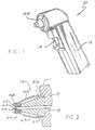
- FIG. 2 is a partial sectional view through the axis of the probe of the thermometer shown in FIG. 1; and
- FIG. 3 is an exploded view of the thermal isolation boot and the heat sink containing the waveguide portion of the probe of FIG. 1.
-
- As is shown in the exemplary drawings, the invention is embodied in a thermal isolation apparatus for a probe of a biomedical thermometer. The probe includes a waveguide which receives and channels infrared radiation to an infrared detector in the body of the thermometer. The thermal isolation apparatus isolates the waveguide and other optical path components from producing or receiving extraneous thermal influences which may arise during use.
- Referring now to FIGS. 1 and 2, a biomedical
infrared thermometer 10 is shown for sensing the temperature of a patient. The body of the biomedical thermometer 11 houses an infrared radiation detector (not shown) and functional elements necessary for the detection of the temperature of the patient based upon the infrared radiation received by the thermometer from a body cavity such as the tympanic canal, or other portions of the patient's anatomy. The thermometer is preferably a hand held type including ahandle 12, and an on-off trigger switch 14, so that the temperature readings may be quickly taken by the user by pointing theprotruding probe 16 end at the target area of the patient from which a temperature reading is to be taken, such as the tympanic membrane. - The
probe 16 includes awaveguide portion 18, which is preferably formed of a highly thermally conductive material such as copper, although it may be formed of other good heat conductive and reflective or platable material such as aluminum, brass, stainless steel, or the like. Surrounding thewaveguide 18 is aheat sink 20. The heat sink may be integral with thewaveguide 18 or may be a supporting structure within which the waveguide is mounted. Preferably, the waveguide is formed by forming a channel through the heat sink and plating the channel with a substance which is highly reflective to infrared energy, such as gold. In another embodiment, the waveguide may be formed by inserting an intimately bonded sleeve of reflective material into the channel. The heat sink is in thermal communication with aheat sink 19 in the body 11 of the thermometer formed of a similar material. In the embodiment shown in FIG. 2, the waveguide is generally cylindrical in shape and extends axially through theheat sink 20 for communication of infrared energy from the temperature source to the infrared detector. - In another embodiment, the waveguide is frustro-conically shaped with the larger opening at the distal end of the probe for directed at the patient. The smaller opening was located facing to the IR detector in the body of the thermometer. This configuration resulted in more IR energy from the patient reaching the detector. In this embodiment, the waveguide opening at the distal end of the probe was selected to be a particular size based on the opening of the average ear. This size was larger than the size of the waveguide opening permitted by the particular detector used. Thus a frustro-conically shaped waveguide was used, although with other applications, a differently shaped waveguide may be more appropriate.
- Referring now to FIGS. 2 and 3, a
window 22 is disposed at the end of thewaveguide 18, and is mounted and protected in atransparent sleeve 23 placed over the distal tip of thewaveguide 18 and thewindow 22. Thewindow 22 may be formed of a glass-like material such as zinc selenide which is substantially transparent to infrared energy. Alternatively, the window could be made of polyethylene or other similar materials that are also substantially transparent to infrared energy. In the embodiment disclosed, the zinc selenide window passes the infrared energy while sealing the end of the waveguide from contamination. - The
sleeve 23 is preferably generally tubular and is made of a rugged material such as stainless steel to protect thewindow 22 and waveguide end. Additionally, the material is chosen to have a low thermal conductivity to provide additional insulation for these same two elements. In one embodiment, low thermal conductivity stainless steel was used. Thesleeve 23 may also include aflange 32 at one end to fit snugly against a correspondingly inset portion of theheat sink 20. Thesleeve 23 preferably includes a lip (not shown) around the inside of the end of the sleeve away from theflange end 25 for retention of thewindow 22 during assembly, and a series of holes (not shown) around the lip end of the sleeve through which adhesive may be applied to the edge of the window to permanently bond it in place in thesleeve 23. Thewindow 22 and thesleeve 23 assembly can therefore be readily removed and replaced by sliding thesleeve 23 off the end of thewaveguide 18. - The
heat sink 20 shown in FIGS. 2 and 3, is generally conically shaped so that it will fit inside theouter boot 24 as is discussed below. Theheat sink 20 is used to insulate thewaveguide 18 from extraneous heat sources and to avoid the generation of "hot spots" or temperature variations along the waveguide. As used herein, hot spots are areas of significantly different temperature from the average temperature of the waveguide. When the probe is used to measure the temperature of a patient, it may come into contact with the patient at a point or points on the probe. It is desirable that the heat of the patient received by the probe due to contact at this point or points, not be conducted to the waveguide or if it is, at least be conducted evenly around the waveguide so that hot spots are not formed. In order to resist the formation of hot spots, theheat sink 20 is formed of a material having high thermal conductivity and diffusivity. By using such a material, the heat conducted to the heat sink at this point or points will be evenly distributed throughout the heat sink and along the waveguide. Additionally, the mass of theheat sink 20 is selected to have a high heat capacity. Depending on its size, the heat sink may present such a large heat capacity to the heat or cold source, that before any temperature change can reach the waveguide, which is located at the center of the heat sink, the temperature measurement of the patient will have been completed. In the embodiment shown in the FIGS., theheat sink 20 was formed of copper. In addition to having high thermal conductivity, high thermal diffusivity and sufficient mass for high heat capacity, it provides an excellent surface on which to plate highly thermally conductive materials, such as gold, to form thewaveguide 18. - Another means of thermally isolating the probe includes forming a closed air space around the optical path. Mounted over the
heat sink 20 of the probe is anouter boot 24 which contacts theheat sink 20 at theproximal base portion 26 of the boot, and contacts thesleeve 23 at the distal tip portion 28 of the boot. The outer boot may be approximately 2.54 mm (0.10 inch) thick and is preferably formed of a durable, hard plastic such as ABS, which is well known for its durability and thermal insulation properties and which can be plated with reflective materials. However, other materials may also be suitable. One ormore tabs 27 are preferably provided for interfacing with corresponding slots (not shown) in the body 11 of the thermometer for securing theboot 24 to the thermometer. The inner surface of the boot between the proximal and distal areas of contact with thewaveguide 18 is preferably spaced from the outer surface of thewaveguide 18 by typically approximately 1.02 tmm (0.04 inches) although the spacing can vary, depending on the amount of air desired. A chamber forming a closed air space orair gap 25 is thereby formed between the boot and the waveguide, providing a layer of insulative air around the probe to further protect the waveguide channel from transient temperature changes due to patient contact or other extraneous thermal sources and protecting the. target from temperature change due to contact with the probe. - The air gap preferably extends inside the
boot 24 from the area where theproximal base portion 26 of the boot contacts theheat sink 20 to an area approximately where the distal tip portion 28 of the boot contacts thesleeve 23 over the distal tip of the probe. The distal tip 28 of the boot is preferably involuted to form an inwardly foldedextension 29 which slips over thesleeve 23. This configuration holds the window and sleeve in position at the distal end of thewaveguide 18. The air gap therefore extends forwardly between this inwardly foldedextension 29 and thebase portion 26 of the boot so that the air gap thermally isolates the entire length of the waveguide in the probe from thermal influences outside the boot. - In considering the amount of thermal isolation required for the probe, at least three situations would typically be considered: 1) the patient could be hot relative to the temperature of the probe; 2) the patient could be cold relative to the temperature of the probe; and 3) the protective probe cover placed over the probe for hygienic and protective reasons could be either hot or cold relative to the probe temperature.
- In addition to the above three situations, two other factors are normally considered when determining the dimension of the air gap: 1) the amount of time the detector takes to complete its temperature measurement; and 2) the typical amount of time that the instrument operator will leave the probe in contact with the patient while taking the patient's temperature.
- In an embodiment of the invention, an air gap formed between the
heat sink 20 and the inside surface of theouter boot 24 within the range 0.51 to 1.52 mm (0.020 to 0.060 in.) was found to be very effective in isolating the optical path in the probe from external temperature influences encountered in normal use. Thus the combination of a heat sink with high thermal diffusivity, high thermal conductivity, sufficient thermal mass for high heat capacity and a closed air space having low thermal diffusivity and conductivity results in relative thermal isolation. The heat sink and air gap thermally isolate the infrared optical path in the probe portion of the thermometer from extraneous thermal changes. Additionally, the combination of the two provide enough thermal protection such that a measurement may be completed prior to thermal influences reaching the waveguide.
Claims (7)
- A probe (16) having replaceable elements adapted to communicate electromagnetic energy in the form of infrared radiation from a patient to an energy detector, the probe (16) comprising a distal opening through which energy from the patient enters the probe and an energy conducting path to the energy detector, characterized in that the probe (16) includes;a replaceable window (22) formed of a rigid material transparent to said electromagnetic energy, the window (22) being mounted in the energy conducting path of the probe as part of an assembly (22, 23) configured to removably position the window (22) such that the assembly (22, 23) is readily removed and replaced; andan outer boot (24) removably positioned over the energy conducting path and the replaceable window (22) and mounted such that the outer boot (24) must be removed before the replaceable window can be removed and replaced.
- The probe according to claim 1, further characterized in that the outer removable boot (24) is configured to secure the window (22) at a position internal to the boot (24) and to firmly retain the window (22) at a position in the energy path such that the window (22) is not removable until after the boot (24) has been removed.
- The probe according to claim 1 or claim 2, further characterized in that:the replaceable window (22) is mounted in an assembly (22, 23) which includes a replaceable sleeve (23) having an opening within which the window (22) is mounted into position; andthe removable boot contacts the sleeve (23) and retains the sleeve (23) and the window (22) at positions in the energy conducting path wherein the sleeve (23) and the window (22) may be removed from the energy conducting path and replaced after the boot (24) has been removed.
- The probe according to claim 3, further characterized in that:the sleeve (23) comprises a mounting flange (25);the energy conducting path comprises a mounting surface on which the sleeve is slidably mounted; and the outer boot comprises a window retainer wherein the window retainer of the outer boot contacts the flange (25) of the sleeve (23) to secure the sleeve (23) on the mounting surface such that the window (22) is positioned at the position in the energy path when the boot (24) is in place, and the sleeve (23) and window (22) are slidably removable from the energy conducting path and can be replaced when the boot (24) is removed from the probe (16).
- The probe according to claim 3, further characterized in that the mounting surface of the energy conducting path comprises an inset portion for receiving the flange (25) of the sleeve (23).
- The probe (16) according to any of claims 1 through 5, further characterized in that:the removable outer boot (24) is formed of a durable material; andthe removable outer boot extends distally beyond the replaceable window (22) to provide shock protection to the window.
- The probe according to claims 1 through 5, further characterized in that:the removable outer boot (24) is formed of a durable material and comprises a distal involution; andthe involution of the removable outer boot (24) extends distally beyond the window (22) to provide shock protection to the window (22).
Applications Claiming Priority (3)
| Application Number | Priority Date | Filing Date | Title |
|---|---|---|---|
| US49033690A | 1990-03-08 | 1990-03-08 | |
| US490336 | 1990-03-08 | ||
| EP91103428A EP0445783B1 (en) | 1990-03-08 | 1991-03-06 | Thermally isolated probe |
Related Parent Applications (2)
| Application Number | Title | Priority Date | Filing Date |
|---|---|---|---|
| EP91103428A Division EP0445783B1 (en) | 1990-03-08 | 1991-03-06 | Thermally isolated probe |
| EP91103428.8 Division | 1991-03-06 |
Publications (3)
| Publication Number | Publication Date |
|---|---|
| EP0674162A2 EP0674162A2 (en) | 1995-09-27 |
| EP0674162A3 EP0674162A3 (en) | 1995-10-18 |
| EP0674162B1 true EP0674162B1 (en) | 2002-01-02 |
Family
ID=23947618
Family Applications (2)
| Application Number | Title | Priority Date | Filing Date |
|---|---|---|---|
| EP91103428A Expired - Lifetime EP0445783B1 (en) | 1990-03-08 | 1991-03-06 | Thermally isolated probe |
| EP95109123A Expired - Lifetime EP0674162B1 (en) | 1990-03-08 | 1991-03-06 | Thermally isolated probe |
Family Applications Before (1)
| Application Number | Title | Priority Date | Filing Date |
|---|---|---|---|
| EP91103428A Expired - Lifetime EP0445783B1 (en) | 1990-03-08 | 1991-03-06 | Thermally isolated probe |
Country Status (5)
| Country | Link |
|---|---|
| US (1) | US6332090B1 (en) |
| EP (2) | EP0445783B1 (en) |
| JP (1) | JP2603003B2 (en) |
| CA (1) | CA2037775C (en) |
| DE (2) | DE69116903T2 (en) |
Cited By (5)
| Publication number | Priority date | Publication date | Assignee | Title |
|---|---|---|---|---|
| US7668731B2 (en) | 2002-01-11 | 2010-02-23 | Baxter International Inc. | Medication delivery system |
| US8234128B2 (en) | 2002-04-30 | 2012-07-31 | Baxter International, Inc. | System and method for verifying medical device operational parameters |
| US8775196B2 (en) | 2002-01-29 | 2014-07-08 | Baxter International Inc. | System and method for notification and escalation of medical data |
| US10061899B2 (en) | 2008-07-09 | 2018-08-28 | Baxter International Inc. | Home therapy machine |
| US10173008B2 (en) | 2002-01-29 | 2019-01-08 | Baxter International Inc. | System and method for communicating with a dialysis machine through a network |
Families Citing this family (42)
| Publication number | Priority date | Publication date | Assignee | Title |
|---|---|---|---|---|
| DE19604201A1 (en) | 1996-02-06 | 1997-08-07 | Braun Ag | protective cap |
| JP3615359B2 (en) * | 1997-07-16 | 2005-02-02 | テルモ株式会社 | Ear thermometer |
| EP1688724A3 (en) * | 1997-07-16 | 2008-06-04 | Terumo Kabushiki Kaisha | Ear type clinical-thermometer |
| IL126224A0 (en) * | 1998-09-15 | 1999-05-09 | Gerlitz Jonathan | Ear thermometer and detector therefor |
| US6547745B1 (en) * | 1999-06-23 | 2003-04-15 | Eliahu Rubinstein | Fever alarm system |
| DE19929503B4 (en) * | 1999-06-28 | 2008-06-26 | Braun Gmbh | IR thermometers for different measuring locations |
| US6319206B1 (en) | 1999-11-24 | 2001-11-20 | Exergen Corporation | Temporal thermometer disposable cap |
| DE10025157A1 (en) | 2000-05-23 | 2001-11-29 | Braun Gmbh | Infrared radiation thermometer with changeable measuring tip |
| WO2001096825A1 (en) * | 2000-06-13 | 2001-12-20 | Omron Corporation | Pyrometer |
| JP3945189B2 (en) * | 2001-06-01 | 2007-07-18 | オムロンヘルスケア株式会社 | Infrared thermometer |
| ITVA20020014A1 (en) * | 2002-02-19 | 2003-08-19 | Tecnimed Srl | HYGIENIC HOOD FOR INFARRED CONTACT THERMOMETERS |
| ATE523770T1 (en) | 2002-12-12 | 2011-09-15 | Covidien Ag | METHOD FOR ASSEMBLING AN EAR THERMOMETER |
| US7434991B2 (en) | 2002-12-12 | 2008-10-14 | Covidien Ag | Thermal tympanic thermometer |
| US7478946B2 (en) | 2003-01-06 | 2009-01-20 | Covidien Ag | Probe cover cassette with improved probe cover support |
| US7354194B2 (en) * | 2003-01-06 | 2008-04-08 | Covidien Ag | Tympanic thermometer probe cover with film support mechanism |
| EP1631222B1 (en) * | 2003-05-22 | 2007-01-03 | Medoc Ltd. | Thermal stimulation probe and method |
| US20050002437A1 (en) * | 2003-07-02 | 2005-01-06 | Jacob Fraden | Probe for a body cavity |
| US7354399B2 (en) * | 2003-07-28 | 2008-04-08 | Welch Allyn, Inc. | Otoscopic tip element and related method of use |
| US7083330B1 (en) * | 2004-10-19 | 2006-08-01 | Huang Hua Co., Ltd. | Ear thermometer having breakable ear cap |
| TW200615520A (en) * | 2004-11-09 | 2006-05-16 | Norm Pacific Automat Corp | Infrared thermometer |
| US8496647B2 (en) * | 2007-12-18 | 2013-07-30 | Intuitive Surgical Operations, Inc. | Ribbed force sensor |
| US20070248141A1 (en) * | 2006-04-21 | 2007-10-25 | Sherwood Services Ag | Infrared thermometer and probe cover thereof |
| DE102006023704A1 (en) * | 2006-05-19 | 2007-11-22 | BSH Bosch und Siemens Hausgeräte GmbH | Hob with a sensor device |
| TW200921063A (en) * | 2007-11-09 | 2009-05-16 | Actherm Inc | Probe cover for ear thermometer and manufacturing method thereof |
| US8561473B2 (en) | 2007-12-18 | 2013-10-22 | Intuitive Surgical Operations, Inc. | Force sensor temperature compensation |
| US8554579B2 (en) | 2008-10-13 | 2013-10-08 | Fht, Inc. | Management, reporting and benchmarking of medication preparation |
| US8480296B2 (en) * | 2009-03-19 | 2013-07-09 | United States Of America As Represented By The Administrator Of The National Aeronautics Space Administration | Low temperature radiometer |
| US8231271B2 (en) * | 2009-04-09 | 2012-07-31 | Welch Allyn, Inc. | IR thermometry probe cover |
| US8876373B2 (en) | 2009-04-09 | 2014-11-04 | Welch Allyn, Inc. | IR thermometry probe cover |
| USD787683S1 (en) | 2009-04-09 | 2017-05-23 | Welch Allyn, Inc. | Cover for a probe |
| US8186876B2 (en) * | 2009-04-20 | 2012-05-29 | Welch Allyn, Inc. | Calibrated assembly for IR thermometer apparatus |
| US8136985B2 (en) * | 2009-05-05 | 2012-03-20 | Welch Allyn, Inc. | IR thermometer thermal isolation tip assembly |
| US8753008B2 (en) * | 2009-06-26 | 2014-06-17 | Fluke Corporation | Protective enclosure for a thermal imaging device of an industrial monitoring system |
| DE102010004035A1 (en) * | 2010-01-05 | 2011-07-07 | EOS GmbH Electro Optical Systems, 82152 | Device for the generative production of a three-dimensional object with an insulated construction field |
| US9357930B2 (en) * | 2012-03-19 | 2016-06-07 | Welch Allyn, Inc. | Temperature measurement system |
| EP3346444B1 (en) | 2012-10-26 | 2020-09-23 | Baxter Corporation Englewood | Improved image acquisition for medical dose preparation system |
| AU2013335278B2 (en) | 2012-10-26 | 2016-03-24 | Baxter Corporation Englewood | Improved work station for medical dose preparation system |
| DE102012223691A1 (en) * | 2012-12-19 | 2014-06-26 | Heine Optotechnik Gmbh & Co Kg | Otoscope with disposable ear funnel |
| US11107574B2 (en) | 2014-09-30 | 2021-08-31 | Baxter Corporation Englewood | Management of medication preparation with formulary management |
| WO2016090091A1 (en) | 2014-12-05 | 2016-06-09 | Baxter Corporation Englewood | Dose preparation data analytics |
| WO2016141216A1 (en) | 2015-03-03 | 2016-09-09 | Baxter Corporation Englewood | Pharmacy workflow management with integrated alerts |
| CN113927872A (en) * | 2021-11-19 | 2022-01-14 | 阿姆斯壮地面材料(中国)有限公司 | Novel screw element |
Family Cites Families (39)
| Publication number | Priority date | Publication date | Assignee | Title |
|---|---|---|---|---|
| US2661454A (en) | 1948-03-12 | 1953-12-01 | Honeywell Regulator Co | Control apparatus |
| US2696117A (en) | 1950-06-24 | 1954-12-07 | Honeywell Regulator Co | Radiation pyrometer |
| US3277715A (en) | 1962-06-27 | 1966-10-11 | Lion Res Corp | Method of and apparatus for measuring the emittance of a radiation-emitting surface |
| US3282106A (en) * | 1963-01-28 | 1966-11-01 | Barnes Eng Co | Method of measuring body temperature |
| US3368076A (en) | 1965-08-18 | 1968-02-06 | Trw Inc | Conical receiver for thermal radiation |
| US3581570A (en) * | 1967-09-05 | 1971-06-01 | Garrett Corp | Thermal radiation sensor |
| US3491596A (en) * | 1967-10-02 | 1970-01-27 | Vito Charles P De | Temperature sensing device |
| US3531992A (en) * | 1968-07-12 | 1970-10-06 | Leeds & Northrup Co | Expendable tympanic membrane thermometer |
| US3878836A (en) | 1973-08-23 | 1975-04-22 | Products Int Marketing | Disposable speculum for tympanic thermometer |
| US4005605A (en) | 1974-07-22 | 1977-02-01 | Mikron Instrument Company, Inc. | Remote reading infrared thermometer |
| US3942891A (en) | 1975-01-29 | 1976-03-09 | Barnes Engineering Company | Radiometer probe |
| US4301682A (en) | 1979-08-24 | 1981-11-24 | Everest Charles E | Infrared thermometer in making stress-degree measurements for irrigation purposes |
| DE2953811A1 (en) | 1979-09-12 | 1982-02-11 | M Jacobs | HAND HERO DIGITAL TEMPERATURE MEASURING INSTRUMENT |
| FR2487512A1 (en) | 1980-07-22 | 1982-01-29 | Thomson Csf | INFRARED RADIATION DETECTOR DEVICE |
| US4380998A (en) | 1981-01-05 | 1983-04-26 | Welch Allyn, Inc. | Soft tip speculum |
| US4527896A (en) | 1982-03-04 | 1985-07-09 | Mikron Instrument Company, Inc. | Infrared transducer-transmitter for non-contact temperature measurement |
| US5179936A (en) * | 1984-10-23 | 1993-01-19 | Intelligent Medical Systems, Inc. | Disposable speculum with membrane bonding ring |
| US4662360A (en) * | 1984-10-23 | 1987-05-05 | Intelligent Medical Systems, Inc. | Disposable speculum |
| US4790324A (en) * | 1984-10-23 | 1988-12-13 | Intelligent Medical Systems, Inc. | Method and apparatus for measuring internal body temperature utilizing infrared emissions |
| US4602642A (en) * | 1984-10-23 | 1986-07-29 | Intelligent Medical Systems, Inc. | Method and apparatus for measuring internal body temperature utilizing infrared emissions |
| DE786649T1 (en) * | 1985-04-17 | 1998-05-14 | Thermoscan Inc | Electronic infrared thermometer and method for temperature measurement |
| US4636091A (en) * | 1985-06-27 | 1987-01-13 | Exergen Corporation | Radiation detector having temperature readout |
| US4722612A (en) | 1985-09-04 | 1988-02-02 | Wahl Instruments, Inc. | Infrared thermometers for minimizing errors associated with ambient temperature transients |
| US4784149A (en) * | 1986-01-13 | 1988-11-15 | Optical Sensors, Inc. | Infrared thermometer with automatic calibration |
| CS259738B1 (en) * | 1986-04-30 | 1988-10-14 | Rudolf Hendrich | Dipping probe for single temperature measuring |
| JPS63292027A (en) * | 1987-05-26 | 1988-11-29 | Babcock Hitachi Kk | Temperature sensor |
| WO1989006348A1 (en) * | 1987-12-25 | 1989-07-13 | Nippon Steel Corporation | Optical thermometer |
| JP2826337B2 (en) * | 1988-04-12 | 1998-11-18 | シチズン時計株式会社 | Radiation thermometer |
| US4895164A (en) * | 1988-09-15 | 1990-01-23 | Telatemp Corp. | Infrared clinical thermometer |
| US4911559A (en) * | 1988-11-01 | 1990-03-27 | Diatek, Inc. | Disposable probe cover assembly for medical thermometer |
| US5018872A (en) * | 1988-11-01 | 1991-05-28 | Diatek, Inc. | Probe assembly for infrared thermometer |
| US4863281A (en) * | 1988-11-01 | 1989-09-05 | Diatak, Inc. | Probe cover ejection apparatus for medical thermometer |
| US5012813A (en) * | 1988-12-06 | 1991-05-07 | Exergen Corporation | Radiation detector having improved accuracy |
| US4993419A (en) * | 1988-12-06 | 1991-02-19 | Exergen Corporation | Radiation detector suitable for tympanic temperature measurement |
| US4900162A (en) * | 1989-03-20 | 1990-02-13 | Ivac Corporation | Infrared thermometry system and method |
| US5163418A (en) * | 1989-09-19 | 1992-11-17 | Thermoscan Inc. | Speculum cover |
| US5066142A (en) * | 1990-03-08 | 1991-11-19 | Ivac Corporation | Protective apparatus for a biomedical probe |
| JPH0741026B2 (en) * | 1990-08-30 | 1995-05-10 | ヒロセ電機株式会社 | Thermometer |
| US5167235A (en) * | 1991-03-04 | 1992-12-01 | Pat O. Daily Revocable Trust | Fiber optic ear thermometer |
-
1991
- 1991-03-06 DE DE69116903T patent/DE69116903T2/en not_active Expired - Lifetime
- 1991-03-06 EP EP91103428A patent/EP0445783B1/en not_active Expired - Lifetime
- 1991-03-06 DE DE69132890T patent/DE69132890T2/en not_active Expired - Lifetime
- 1991-03-06 EP EP95109123A patent/EP0674162B1/en not_active Expired - Lifetime
- 1991-03-07 CA CA002037775A patent/CA2037775C/en not_active Expired - Lifetime
- 1991-03-07 JP JP3067912A patent/JP2603003B2/en not_active Expired - Lifetime
-
1995
- 1995-06-01 US US08/458,010 patent/US6332090B1/en not_active Expired - Lifetime
Cited By (9)
| Publication number | Priority date | Publication date | Assignee | Title |
|---|---|---|---|---|
| US7668731B2 (en) | 2002-01-11 | 2010-02-23 | Baxter International Inc. | Medication delivery system |
| US8775196B2 (en) | 2002-01-29 | 2014-07-08 | Baxter International Inc. | System and method for notification and escalation of medical data |
| US10173008B2 (en) | 2002-01-29 | 2019-01-08 | Baxter International Inc. | System and method for communicating with a dialysis machine through a network |
| US8234128B2 (en) | 2002-04-30 | 2012-07-31 | Baxter International, Inc. | System and method for verifying medical device operational parameters |
| US10061899B2 (en) | 2008-07-09 | 2018-08-28 | Baxter International Inc. | Home therapy machine |
| US10068061B2 (en) | 2008-07-09 | 2018-09-04 | Baxter International Inc. | Home therapy entry, modification, and reporting system |
| US10095840B2 (en) | 2008-07-09 | 2018-10-09 | Baxter International Inc. | System and method for performing renal therapy at a home or dwelling of a patient |
| US10224117B2 (en) | 2008-07-09 | 2019-03-05 | Baxter International Inc. | Home therapy machine allowing patient device program selection |
| US10089443B2 (en) | 2012-05-15 | 2018-10-02 | Baxter International Inc. | Home medical device systems and methods for therapy prescription and tracking, servicing and inventory |
Also Published As
| Publication number | Publication date |
|---|---|
| DE69132890T2 (en) | 2002-08-29 |
| CA2037775C (en) | 1995-10-17 |
| EP0445783A3 (en) | 1992-04-29 |
| DE69116903T2 (en) | 1996-10-02 |
| EP0445783A2 (en) | 1991-09-11 |
| JPH05261069A (en) | 1993-10-12 |
| DE69116903D1 (en) | 1996-03-21 |
| JP2603003B2 (en) | 1997-04-23 |
| EP0674162A3 (en) | 1995-10-18 |
| US6332090B1 (en) | 2001-12-18 |
| DE69132890D1 (en) | 2002-02-07 |
| EP0445783B1 (en) | 1996-02-07 |
| CA2037775A1 (en) | 1991-09-09 |
| EP0674162A2 (en) | 1995-09-27 |
Similar Documents
| Publication | Publication Date | Title |
|---|---|---|
| EP0674162B1 (en) | Thermally isolated probe | |
| CA2037746C (en) | Protective apparatus for a biomedical probe | |
| WO1998019143A1 (en) | Axillary infrared thermometer and method of use | |
| US7841767B2 (en) | Thermal tympanic thermometer | |
| EP1857795B1 (en) | Tympanic thermometer | |
| JPH0528617B2 (en) | ||
| KR100279338B1 (en) | Infrared thermometer | |
| US5018872A (en) | Probe assembly for infrared thermometer | |
| WO1996008994A1 (en) | Tympanic thermometer | |
| US20060098709A1 (en) | Infrared thermometer | |
| US20060153272A1 (en) | Ear thermometer | |
| US20020186745A1 (en) | Axillary infrared thermometer and method of use | |
| JPH05261070A (en) | Protective device for biomedical probe | |
| WO2005083375A1 (en) | A probe assembly for an infrared medical thermometer and an infrared medical thermometer |
Legal Events
| Date | Code | Title | Description |
|---|---|---|---|
| PUAI | Public reference made under article 153(3) epc to a published international application that has entered the european phase |
Free format text: ORIGINAL CODE: 0009012 |
|
| PUAL | Search report despatched |
Free format text: ORIGINAL CODE: 0009013 |
|
| AC | Divisional application: reference to earlier application |
Ref document number: 445783 Country of ref document: EP |
|
| AK | Designated contracting states |
Kind code of ref document: A2 Designated state(s): DE GB |
|
| AK | Designated contracting states |
Kind code of ref document: A3 Designated state(s): DE GB |
|
| 17P | Request for examination filed |
Effective date: 19960411 |
|
| RAP1 | Party data changed (applicant data changed or rights of an application transferred) |
Owner name: IVAC MEDICAL SYSTEMS, INC. |
|
| RAP1 | Party data changed (applicant data changed or rights of an application transferred) |
Owner name: IVAC MEDICAL SYSTEMS, INC. |
|
| 17Q | First examination report despatched |
Effective date: 19970507 |
|
| RAP1 | Party data changed (applicant data changed or rights of an application transferred) |
Owner name: ALARIS MEDICAL SYSTEMS, INC. |
|
| GRAG | Despatch of communication of intention to grant |
Free format text: ORIGINAL CODE: EPIDOS AGRA |
|
| GRAG | Despatch of communication of intention to grant |
Free format text: ORIGINAL CODE: EPIDOS AGRA |
|
| GRAH | Despatch of communication of intention to grant a patent |
Free format text: ORIGINAL CODE: EPIDOS IGRA |
|
| GRAH | Despatch of communication of intention to grant a patent |
Free format text: ORIGINAL CODE: EPIDOS IGRA |
|
| GRAA | (expected) grant |
Free format text: ORIGINAL CODE: 0009210 |
|
| REG | Reference to a national code |
Ref country code: GB Ref legal event code: IF02 |
|
| AC | Divisional application: reference to earlier application |
Ref document number: 445783 Country of ref document: EP |
|
| AK | Designated contracting states |
Kind code of ref document: B1 Designated state(s): DE GB |
|
| REF | Corresponds to: |
Ref document number: 69132890 Country of ref document: DE Date of ref document: 20020207 |
|
| PLBE | No opposition filed within time limit |
Free format text: ORIGINAL CODE: 0009261 |
|
| STAA | Information on the status of an ep patent application or granted ep patent |
Free format text: STATUS: NO OPPOSITION FILED WITHIN TIME LIMIT |
|
| 26N | No opposition filed | ||
| PGFP | Annual fee paid to national office [announced via postgrant information from national office to epo] |
Ref country code: GB Payment date: 20100303 Year of fee payment: 20 |
|
| PGFP | Annual fee paid to national office [announced via postgrant information from national office to epo] |
Ref country code: DE Payment date: 20100318 Year of fee payment: 20 |
|
| REG | Reference to a national code |
Ref country code: DE Ref legal event code: R071 Ref document number: 69132890 Country of ref document: DE |
|
| REG | Reference to a national code |
Ref country code: GB Ref legal event code: PE20 Expiry date: 20110305 |
|
| PG25 | Lapsed in a contracting state [announced via postgrant information from national office to epo] |
Ref country code: GB Free format text: LAPSE BECAUSE OF EXPIRATION OF PROTECTION Effective date: 20110305 |
|
| PG25 | Lapsed in a contracting state [announced via postgrant information from national office to epo] |
Ref country code: DE Free format text: LAPSE BECAUSE OF EXPIRATION OF PROTECTION Effective date: 20110306 |