EP0673107A2 - Bus structure for power system - Google Patents
Bus structure for power system Download PDFInfo
- Publication number
- EP0673107A2 EP0673107A2 EP95301490A EP95301490A EP0673107A2 EP 0673107 A2 EP0673107 A2 EP 0673107A2 EP 95301490 A EP95301490 A EP 95301490A EP 95301490 A EP95301490 A EP 95301490A EP 0673107 A2 EP0673107 A2 EP 0673107A2
- Authority
- EP
- European Patent Office
- Prior art keywords
- plug
- power
- modules
- module
- backplane
- Prior art date
- Legal status (The legal status is an assumption and is not a legal conclusion. Google has not performed a legal analysis and makes no representation as to the accuracy of the status listed.)
- Withdrawn
Links
Images


Classifications
-
- H—ELECTRICITY
- H02—GENERATION; CONVERSION OR DISTRIBUTION OF ELECTRIC POWER
- H02M—APPARATUS FOR CONVERSION BETWEEN AC AND AC, BETWEEN AC AND DC, OR BETWEEN DC AND DC, AND FOR USE WITH MAINS OR SIMILAR POWER SUPPLY SYSTEMS; CONVERSION OF DC OR AC INPUT POWER INTO SURGE OUTPUT POWER; CONTROL OR REGULATION THEREOF
- H02M7/00—Conversion of ac power input into dc power output; Conversion of dc power input into ac power output
- H02M7/003—Constructional details, e.g. physical layout, assembly, wiring or busbar connections
-
- H—ELECTRICITY
- H02—GENERATION; CONVERSION OR DISTRIBUTION OF ELECTRIC POWER
- H02B—BOARDS, SUBSTATIONS OR SWITCHING ARRANGEMENTS FOR THE SUPPLY OR DISTRIBUTION OF ELECTRIC POWER
- H02B1/00—Frameworks, boards, panels, desks, casings; Details of substations or switching arrangements
Definitions
- This invention relates to power system plants in which intermediate power processing modules are mounted in a hoousing structure of a power plant and between an input and output power access modules of that plant; and in particular to a backplane bus structure providing a particular control structure for accepting and controlling different types of inserted power processing modules.
- Power plant systems having input and output power access with intermediate power processors are usually designed with a particular control structure and with anticipated operation using only one type of intermediate plug-in processor.
- the overall plant structure is usually limited to one type of control and is not readily changeable to use plug-in power processors of the other type control and power output and hence can not accommodate differing plug-in power processing modules.
- a power system plant includes a backplane arrangement including a primary and secondary bus to which intermediate power processing modules are selectively connected to the input and output power control and monitors of the plant.
- the backplane connections of the plug-in intermediate power processing modules are unique to the type of plug-in module placed on an input shelf (i.e. rectifier or converter plug-in module) and how the plant is to be operated.
- the connections of these plug-in modules to the backplane connector are such that the plug-in module is designed to have its connectors connect to either primary or secondary referenced control signals.
- the connectors of the backplane accept both type of plug-in modules so that any plug-in module inserted is automatically connected to respond to the appropriate primary or secondary referenced control signals.
- the power plant system includes control signal generators and signal references for the primary bus and the secondary bus.
- the backplane connectors of the plug-in module are designed to connect through the appropriate bus to one or the other of these control signal sources. Its backplane connectors also connect to one or the other of the primary or secondary busses to receive alarm return referenced control signals.
- the power plant system operates in a rectifier or converter plant mode determined by signal interconnections made within the backplane of the system.
- connection receptacles are unique from one another although the connection receptacles are the same regardless of application.
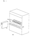
- a power distribution chassis or housing 100 of a power plant as shown in the FIG. 1 includes a plurality of plug-in power modules 101 which slide into a shelf of the housing and connect to a backplane at the rear of the shelf.
- This backplane includes a primary and secondary bus to which the plug-in modules 101 are connected by plug of similar connectors to plug receptacles of the back plane bus structure provided in the housing, which as described below are structured to allow selection to accept a rectifier or converter plug-in module determined by how the plug-in module 101 connects to the backplane structure.
- a plant monitor and control 102 is connected to the backplane in a manner common to use either as a rectifier or converter system. Output power characteristics are monitored by unit 102.
- An output power section 103 (i.e. permanent; not a plug-in module) is connected to the backplane structure and provides power output to a load.
- One of the plug-in power modules 101 is shown prior to insertion into the shelf and consequent connection to the backplane.
- the back plane electrically (not shown) connects the plug-in modules 101 into the electrical system between input and output modules 102,103 and provides power processing of the electrical power there between.
- the input control module 102 normally provides the desired control signals for the plug in modules and is connected to monitor the appropriate monitored signals as determined by the plug-in connection pattern of the plug-in module.
- Plug-in pins are included in a plug-in apparatus 210 in which pins of a plug-in module made with selected receptacles of apparatus 210.
- the input AC power is applied at lead 201 of the power plant housing and is applied individually to each of the plug-in modules. Hence, in a shelf of five modules each would have an AC input.
- Plug-in module 205 is a rectifier module.
- the power output of the rectifier module 205 is applied to a primary bus 208 by means of a mating of connectors of the module 205 in apparatus 210 and in the backplane of the power system housing.
- the primary bus 208 may supply power to a load at output lead 209 or be connected to a lead (209) and connected by a connector in the backplane to a subsequent converter plug-in module 211.
- the converter module 212 connected to apparatus 210 includes conversion circuitry for converting voltage from one DC level to another DC level, or from a DC voltage to an AC voltage. Its output power is applied to a secondary bus 215 via lead 209 which is normally connected to a load to be energized.
- a source of primary reference control signals 207 supplied by the monitor and control is connected to the primary bus 208 and through that bus to the recitifier module 206.
- a source of secondary reference control signals 213 supplied by the monitor and control is connected to the secondary bus 215 and through that bus to the converter module 212
- An alarm return circuit 221 and monitor and control module 222 is included as a module in the plant housing or housing.
- the monitor and control module is connected to the primary bus , via lead 290, to monitor the characteristic power signals of the plant.
- a rectifier 205 is plugged in the connecting leads 251 and 261 are activated through backplane connections to connect to the control circuit 207 of the rectifier and to the primary bus 208 respectively.
- An alarm return circuit 221 is provided for each shelf while the control module 222 is common to the entire power plant.
- the plant operates as an overall system as either a rectifier plant or a converter plant. (note that either plant may include rectifier and converter plug in units)
- the determination of the overall plant operation is set by the connections between the monitor and control unit and the alarm return and the primary referenced control signals and secondary referenced control signals.
- the connections For operation as a rectifier plant system the connections the leads 261 and 271 are enabled and the leads 262 and 272 are disabled.
- leads 261 and 271 are disabled and leads 262 and 272 are enabled. These connections are made within the shelf circuitry of the backplane as shown in the FIG. 2.
- the aforementioned interconnections to the primary bus and secondary bus are controlled by the different portions of hardwired connector geometry or pin arrangement in the back plane of the shelf of the power plant.
- the action of plugging in a rectifier or converter assures connection to the proper control and power train connections to enable the operation of that module automatically in the power system.
- the naming convention defines primary bus power modules to be rectifiers and secondary bus power modules to be converters.
- the signals referenced to the primary output bus are:
- the signals referenced in the alarm return are:
- the signals referenced to the secondary output bus are:
Abstract
Description
- This invention relates to power system plants in which intermediate power processing modules are mounted in a hoousing structure of a power plant and between an input and output power access modules of that plant; and in particular to a backplane bus structure providing a particular control structure for accepting and controlling different types of inserted power processing modules.
- Power plant systems, having input and output power access with intermediate power processors are usually designed with a particular control structure and with anticipated operation using only one type of intermediate plug-in processor. The overall plant structure is usually limited to one type of control and is not readily changeable to use plug-in power processors of the other type control and power output and hence can not accommodate differing plug-in power processing modules.
- A power system plant includes a backplane arrangement including a primary and secondary bus to which intermediate power processing modules are selectively connected to the input and output power control and monitors of the plant. The backplane connections of the plug-in intermediate power processing modules are unique to the type of plug-in module placed on an input shelf (i.e. rectifier or converter plug-in module) and how the plant is to be operated. The connections of these plug-in modules to the backplane connector are such that the plug-in module is designed to have its connectors connect to either primary or secondary referenced control signals. The connectors of the backplane accept both type of plug-in modules so that any plug-in module inserted is automatically connected to respond to the appropriate primary or secondary referenced control signals.
- The power plant system includes control signal generators and signal references for the primary bus and the secondary bus. The backplane connectors of the plug-in module are designed to connect through the appropriate bus to one or the other of these control signal sources. Its backplane connectors also connect to one or the other of the primary or secondary busses to receive alarm return referenced control signals. The power plant system operates in a rectifier or converter plant mode determined by signal interconnections made within the backplane of the system.
- The completed backplane connections for the rectifiers and converters are unique from one another although the connection receptacles are the same regardless of application.
-
- FIG. 1 is a pictorial schematic of a power plant system housing including a plurality of plug in modules which are included to process power between an input and output power module; and
- FIG. 2 is a block schematic of how the plug-in power processing modules may be connected to a backplane bus arrangement of the power plant system housing; and
- FIG. 3 is a table of pinouts at the power module interface.
- A power distribution chassis or
housing 100 of a power plant as shown in the FIG. 1 includes a plurality of plug-inpower modules 101 which slide into a shelf of the housing and connect to a backplane at the rear of the shelf. This backplane includes a primary and secondary bus to which the plug-inmodules 101 are connected by plug of similar connectors to plug receptacles of the back plane bus structure provided in the housing, which as described below are structured to allow selection to accept a rectifier or converter plug-in module determined by how the plug-inmodule 101 connects to the backplane structure. A plant monitor andcontrol 102 is connected to the backplane in a manner common to use either as a rectifier or converter system. Output power characteristics are monitored byunit 102. An output power section 103 (i.e. permanent; not a plug-in module) is connected to the backplane structure and provides power output to a load. One of the plug-inpower modules 101 is shown prior to insertion into the shelf and consequent connection to the backplane. The back plane electrically (not shown) connects the plug-inmodules 101 into the electrical system between input and output modules 102,103 and provides power processing of the electrical power there between. Theinput control module 102 normally provides the desired control signals for the plug in modules and is connected to monitor the appropriate monitored signals as determined by the plug-in connection pattern of the plug-in module. - The organization of a backplane for the power plant housing of FIG. 1, as shown in the FIG. 2, allows the particular connections of the plug-in power processing modules to accept the rectifier and converter plug-in modules on a single shelf. Plug-in pins are included in a plug-in
apparatus 210 in which pins of a plug-in module made with selected receptacles ofapparatus 210. The input AC power is applied at lead 201 of the power plant housing and is applied individually to each of the plug-in modules. Hence, in a shelf of five modules each would have an AC input. Plug-in module 205, as shown in FIG. 2, is a rectifier module. The power output of the rectifier module 205 is applied to aprimary bus 208 by means of a mating of connectors of the module 205 inapparatus 210 and in the backplane of the power system housing. Theprimary bus 208 may supply power to a load at output lead 209 or be connected to a lead (209) and connected by a connector in the backplane to a subsequent converter plug-in module 211. Theconverter module 212 connected toapparatus 210 includes conversion circuitry for converting voltage from one DC level to another DC level, or from a DC voltage to an AC voltage. Its output power is applied to asecondary bus 215 via lead 209 which is normally connected to a load to be energized. - A source of primary
reference control signals 207 supplied by the monitor and control is connected to theprimary bus 208 and through that bus to therecitifier module 206. A source of secondaryreference control signals 213 supplied by the monitor and control is connected to thesecondary bus 215 and through that bus to theconverter module 212 - An
alarm return circuit 221 and monitor andcontrol module 222 is included as a module in the plant housing or housing. The monitor and control module is connected to the primary bus , vialead 290, to monitor the characteristic power signals of the plant. When a rectifier 205 is plugged in the connectingleads 251 and 261 are activated through backplane connections to connect to thecontrol circuit 207 of the rectifier and to theprimary bus 208 respectively. Analarm return circuit 221 is provided for each shelf while thecontrol module 222 is common to the entire power plant. - With a converter 211 plugged in the connecting leads are activated through backplane connections to connect to the secondary
reference control signals 213 and to thesecondary bus 215 respectively. - The plant operates as an overall system as either a rectifier plant or a converter plant. (note that either plant may include rectifier and converter plug in units) The determination of the overall plant operation is set by the connections between the monitor and control unit and the alarm return and the primary referenced control signals and secondary referenced control signals. For operation as a rectifier plant system the connections the
leads leads - The aforementioned interconnections to the primary bus and secondary bus are controlled by the different portions of hardwired connector geometry or pin arrangement in the back plane of the shelf of the power plant. The action of plugging in a rectifier or converter assures connection to the proper control and power train connections to enable the operation of that module automatically in the power system.
- A particular pinout arrangement is shown in the table at FIG. 3.
- The following is a description of the pinouts for the power module interface. The naming convention defines primary bus power modules to be rectifiers and secondary bus power modules to be converters.
- The signals referenced to the primary output bus are:
- R/C+ and R/C-
- Primary bus power output connections.
- RS+ and RS-
- Remote sense leads for the rectifier power modules. These signal pins allow the rectifiers on the primary bus voltage to regulate the output voltage of the plant rather than their own internal voltage.
- R_CM+
- Current monitor output for the rectifiers. This signal interconnects the power modules to the control unit, allowing the control unit to monitor the primary bus output current.
- R_VADJ+ and R_VADJ-
- Rectifier voltage control leads. These signals interconnect the power modules to the control unit to allow the control unit to adjust the primary bus output voltage.
- R_CS+ and R_CS-
- Rectifier current share control leads. These signals interconnect the power modules and allow them to share the output load on the plant.
- The signals referenced in the alarm return are:
- CFA
- Converter fail alarm lead. It interconnects the power modules with the control unit to monitor failures of converters.
- RFA
- Rectifier fail alarm signal lead. It interconnects the power modules with the control unit to allow the control unit to monitor failures of rectifiers.
- C_O/S_OUT
- ON/stby control for the converter. This signal interconnects the control unit by to the power modules on the secondary bus to be able to place them into standby remotely.
- AR
- Alarm return signal lead. This signal is the reference signal for control and monitor functions between the primary and secondary power modules and the control unit.
- R_O/S_OUT
- On/stby control for the rectifiers. It interconnects the rectifiers to the control unit and allows the control unit to place the rectifiers into standby remotely.
- LT
- Lamp test control signal. It interconnects the control unit to the power modules to allow the control unit to initiate lamp test.
- ACF(1) and ACF(2)
- AC fail detection signals from the rectifiers.
- The signals referenced to the secondary output bus are:
- C_CS+
- Current share signal for the secondary power modules.
- C_CM+
- Current monitor signal for a converter only plant.
- RING_ID1 and 2
- Control signal interconnections for ringer modules on the secondary output bus. They allow ringing modules to detect the presence of other ringers in a system.
- C_VADJ+ and C_VADJ-
- Control signals for the secondary output power modules. They interconnect the control unit to the converters or ringers in a converter only plant to allow the control unit to vary the
- C+ and C-
- Secondary output voltage bus connections.
Claims (4)
- A power plant system, including:
a shelf having a plurality of plug-in locations for accepting plug-in power processing modules and including a blackplane connecting arrangement having a primary and secondary bus,
CHARACTERIZED BY
first and second plug-in power processing modules adapted for insertion onto the shelf and each the first and second plug-in power processing modules connecting to the primary and secondary bus in the backplane uniquely as defined by its functionally as a rectifier and converter, respectively;
each plug-in location accepting a unique connection of the first and second plug-in modules defining functionally without modification
the first plug-in modules connected to respond to input related signals of the power plant, and
the second plug-in modules connected to respond to output related signals of the power plant. - A power plant system as claimed in claim 1, wherein:
The first plug-in modules comprise power rectifiers. - A power plant system as claimed in claim 1, wherein:
The second plug-in modules comprise power converters. - A power plant system as claimed in claim 1, wherein:
a monitor and control is included within the power plant and connected to a source of input related signals referenced to an input power and to a source of output related control signals referenced to an output power.
Applications Claiming Priority (2)
| Application Number | Priority Date | Filing Date | Title |
|---|---|---|---|
| US210213 | 1994-03-18 | ||
| US08/210,213 US5623173A (en) | 1994-03-18 | 1994-03-18 | Bus structure for power system |
Publications (2)
| Publication Number | Publication Date |
|---|---|
| EP0673107A2 true EP0673107A2 (en) | 1995-09-20 |
| EP0673107A3 EP0673107A3 (en) | 1996-07-31 |
Family
ID=22782026
Family Applications (1)
| Application Number | Title | Priority Date | Filing Date |
|---|---|---|---|
| EP95301490A Withdrawn EP0673107A3 (en) | 1994-03-18 | 1995-03-08 | Bus structure for power system. |
Country Status (4)
| Country | Link |
|---|---|
| US (2) | US5623173A (en) |
| EP (1) | EP0673107A3 (en) |
| KR (1) | KR950034948A (en) |
| CN (1) | CN1112746A (en) |
Cited By (3)
| Publication number | Priority date | Publication date | Assignee | Title |
|---|---|---|---|---|
| WO1998037620A1 (en) * | 1997-02-07 | 1998-08-27 | Nokia Telecommunications Oy | Output voltage regulation of a power supply module |
| US5880788A (en) * | 1996-03-25 | 1999-03-09 | Interval Research Corporation | Automated synchronization of video image sequences to new soundtracks |
| US8726331B2 (en) | 1999-10-08 | 2014-05-13 | Interval Licensing Llc | System and method for the broadcast dissemination of time-ordered data |
Families Citing this family (13)
| Publication number | Priority date | Publication date | Assignee | Title |
|---|---|---|---|---|
| WO1996027983A1 (en) | 1995-03-07 | 1996-09-12 | Interval Research Corporation | System and method for selective recording of information |
| US5893062A (en) | 1996-12-05 | 1999-04-06 | Interval Research Corporation | Variable rate video playback with synchronized audio |
| US6263507B1 (en) * | 1996-12-05 | 2001-07-17 | Interval Research Corporation | Browser for use in navigating a body of information, with particular application to browsing information represented by audiovisual data |
| US6014319A (en) * | 1998-05-21 | 2000-01-11 | International Business Machines Corporation | Multi-part concurrently maintainable electronic circuit card assembly |
| DE19847789B4 (en) * | 1998-10-16 | 2017-02-23 | Sew-Eurodrive Gmbh & Co Kg | inverter series |
| US6757682B1 (en) | 2000-01-28 | 2004-06-29 | Interval Research Corporation | Alerting users to items of current interest |
| US20040239188A1 (en) * | 2003-05-28 | 2004-12-02 | Hewlett-Packard Development Company, L.P. | Power supply load balancing apparatus |
| US7215216B2 (en) * | 2003-11-20 | 2007-05-08 | The Boeing Company | Apparatus and methods for capacitively-coupled device input/output |
| US20060031916A1 (en) * | 2004-04-30 | 2006-02-09 | Vulcan Inc. | Management and non-linear presentation of broadcasted or streamed multimedia content |
| US20060031879A1 (en) * | 2004-04-30 | 2006-02-09 | Vulcan Inc. | Management and non-linear presentation of news-related broadcasted or streamed multimedia content |
| US20060031885A1 (en) * | 2004-04-30 | 2006-02-09 | Vulcan Inc. | Management and non-linear presentation of music-related broadcasted or streamed multimedia content |
| US7554796B2 (en) * | 2006-01-20 | 2009-06-30 | Adc Telecommunications, Inc. | Modular power distribution system and methods |
| US9118213B2 (en) | 2010-11-24 | 2015-08-25 | Kohler Co. | Portal for harvesting energy from distributed electrical power sources |
Citations (2)
| Publication number | Priority date | Publication date | Assignee | Title |
|---|---|---|---|---|
| DE3541273A1 (en) * | 1985-11-22 | 1987-05-27 | Bbc Brown Boveri & Cie | Converter having a control and regulating device |
| EP0409226A2 (en) * | 1989-07-21 | 1991-01-23 | Hitachi, Ltd. | Power supply control system |
Family Cites Families (8)
| Publication number | Priority date | Publication date | Assignee | Title |
|---|---|---|---|---|
| US4551801A (en) * | 1983-02-07 | 1985-11-05 | Dickey-John Corporation | Modular vehicular monitoring system |
| US4638178A (en) * | 1985-09-03 | 1987-01-20 | Wang Laboratories, Inc. | Modular power system |
| US4675538A (en) * | 1986-06-02 | 1987-06-23 | Epstein Barry M | General purpose uninterruptible power supply |
| NL8602090A (en) * | 1986-08-18 | 1988-03-16 | Philips Nv | METHOD FOR ESTABLISHING A SIGNAL PATH BETWEEN AT LEAST TWO DEVICES AND SYSTEM OF AT LEAST TWO DEVICES FOR REALIZING THE METHOD |
| CA1324650C (en) * | 1988-10-14 | 1993-11-23 | Multitech Systems (Proprietary) Limited | Power supply structure |
| US5089937A (en) * | 1990-07-20 | 1992-02-18 | V Band Corporation | Power interface apparatus for a DC power distribution system |
| US5538436A (en) | 1993-06-29 | 1996-07-23 | Intel Corporation | Two-part memory card socket connector and related interrupt handler |
| US5440449A (en) | 1994-01-26 | 1995-08-08 | Intel Corporation | Wireless communication connector and module for notebook personal computers |
-
1994
- 1994-03-18 US US08/210,213 patent/US5623173A/en not_active Ceased
-
1995
- 1995-03-08 EP EP95301490A patent/EP0673107A3/en not_active Withdrawn
- 1995-03-15 KR KR1019950005289A patent/KR950034948A/en not_active Application Discontinuation
- 1995-03-16 CN CN95102876A patent/CN1112746A/en active Pending
-
1999
- 1999-04-12 US US09/291,650 patent/USRE37182E1/en not_active Expired - Fee Related
Patent Citations (2)
| Publication number | Priority date | Publication date | Assignee | Title |
|---|---|---|---|---|
| DE3541273A1 (en) * | 1985-11-22 | 1987-05-27 | Bbc Brown Boveri & Cie | Converter having a control and regulating device |
| EP0409226A2 (en) * | 1989-07-21 | 1991-01-23 | Hitachi, Ltd. | Power supply control system |
Non-Patent Citations (1)
| Title |
|---|
| APEC'94, vol. 2, 13 - 17 February 1994, ORLANDO,FL, pages 786-792, XP000467393 N.MURAKAMI: "A Highly Efficient, Low-Profile, 300-W Power Pack for Telecommunications Systems" * |
Cited By (4)
| Publication number | Priority date | Publication date | Assignee | Title |
|---|---|---|---|---|
| US5880788A (en) * | 1996-03-25 | 1999-03-09 | Interval Research Corporation | Automated synchronization of video image sequences to new soundtracks |
| WO1998037620A1 (en) * | 1997-02-07 | 1998-08-27 | Nokia Telecommunications Oy | Output voltage regulation of a power supply module |
| US6144572A (en) * | 1997-02-07 | 2000-11-07 | Nokia Telecommunications Oy | Output voltage regulation of a power supply module |
| US8726331B2 (en) | 1999-10-08 | 2014-05-13 | Interval Licensing Llc | System and method for the broadcast dissemination of time-ordered data |
Also Published As
| Publication number | Publication date |
|---|---|
| USRE37182E1 (en) | 2001-05-22 |
| US5623173A (en) | 1997-04-22 |
| KR950034948A (en) | 1995-12-28 |
| EP0673107A3 (en) | 1996-07-31 |
| CN1112746A (en) | 1995-11-29 |
Similar Documents
| Publication | Publication Date | Title |
|---|---|---|
| US5623173A (en) | Bus structure for power system | |
| US5541810A (en) | Expandable programmable controller | |
| US6857896B2 (en) | Smart connect electrical receptacle assembly | |
| ATE363080T1 (en) | CONTROL PANEL FOR CONFIGURING AN UNINTERRUPTIBLE SUPPLY SYSTEM AND BACK PANEL WIRING USED THEREIN | |
| US4789792A (en) | Feeding of matching circuit | |
| US5089937A (en) | Power interface apparatus for a DC power distribution system | |
| US6097303A (en) | Modular input/output system with redundancy and testing | |
| US10554000B2 (en) | Assembly for protection boards of a distribution system | |
| US4692683A (en) | Optical power distribution system | |
| JPH02166946A (en) | Line concentration device for loop type local area network | |
| CN211018381U (en) | Multi-power supply system for self-service equipment | |
| CN209895300U (en) | Power supply adapter plate applied to power supply of server | |
| CN201540532U (en) | Server system | |
| JP3663954B2 (en) | Distributed power system | |
| CN219876552U (en) | Plug-in box type power module | |
| CN109669370B (en) | Signal processor | |
| US5724614A (en) | Circuits provide input/output module connections having the input receptacle being connected to neutral wiring terminal and the output receptacle being connected to hot wiring terminal | |
| JP2763343B2 (en) | Alarm collection control method | |
| JPH0249377A (en) | Power feeding system and connection device | |
| CN115469167A (en) | Microcomputer relay protection testing arrangement | |
| RU98108607A (en) | MODULAR POWER SUPPLY | |
| JPS63208109A (en) | Electronic circuit board | |
| JPH0642389Y2 (en) | Nest for control equipment | |
| JPH0633431Y2 (en) | Aging device for IC | |
| JPH07182074A (en) | Hot-line insertion and pull-out device for hot standby type duplex system |
Legal Events
| Date | Code | Title | Description |
|---|---|---|---|
| PUAI | Public reference made under article 153(3) epc to a published international application that has entered the european phase |
Free format text: ORIGINAL CODE: 0009012 |
|
| AK | Designated contracting states |
Kind code of ref document: A2 Designated state(s): DE FR GB |
|
| PUAL | Search report despatched |
Free format text: ORIGINAL CODE: 0009013 |
|
| AK | Designated contracting states |
Kind code of ref document: A3 Designated state(s): DE FR GB |
|
| RHK1 | Main classification (correction) |
Ipc: H01R 29/00 |
|
| 17P | Request for examination filed |
Effective date: 19970116 |
|
| 17Q | First examination report despatched |
Effective date: 19980327 |
|
| GRAG | Despatch of communication of intention to grant |
Free format text: ORIGINAL CODE: EPIDOS AGRA |
|
| 17Q | First examination report despatched |
Effective date: 19980327 |
|
| GRAG | Despatch of communication of intention to grant |
Free format text: ORIGINAL CODE: EPIDOS AGRA |
|
| GRAG | Despatch of communication of intention to grant |
Free format text: ORIGINAL CODE: EPIDOS AGRA |
|
| GRAH | Despatch of communication of intention to grant a patent |
Free format text: ORIGINAL CODE: EPIDOS IGRA |
|
| STAA | Information on the status of an ep patent application or granted ep patent |
Free format text: STATUS: THE APPLICATION IS DEEMED TO BE WITHDRAWN |
|
| 18D | Application deemed to be withdrawn |
Effective date: 20020115 |