EP0672802A1 - Bauelement - Google Patents
Bauelement Download PDFInfo
- Publication number
- EP0672802A1 EP0672802A1 EP95301574A EP95301574A EP0672802A1 EP 0672802 A1 EP0672802 A1 EP 0672802A1 EP 95301574 A EP95301574 A EP 95301574A EP 95301574 A EP95301574 A EP 95301574A EP 0672802 A1 EP0672802 A1 EP 0672802A1
- Authority
- EP
- European Patent Office
- Prior art keywords
- bridging portion
- cavity
- support means
- wall
- flange
- Prior art date
- Legal status (The legal status is an assumption and is not a legal conclusion. Google has not performed a legal analysis and makes no representation as to the accuracy of the status listed.)
- Withdrawn
Links
- 238000010348 incorporation Methods 0.000 claims abstract description 7
- 239000004793 Polystyrene Substances 0.000 claims abstract description 5
- 229920002223 polystyrene Polymers 0.000 claims abstract description 5
- 238000007665 sagging Methods 0.000 abstract 1
- 239000000463 material Substances 0.000 description 11
- 239000000853 adhesive Substances 0.000 description 5
- 230000001070 adhesive effect Effects 0.000 description 5
- 210000002105 tongue Anatomy 0.000 description 5
- 238000004519 manufacturing process Methods 0.000 description 4
- XLYOFNOQVPJJNP-UHFFFAOYSA-N water Substances O XLYOFNOQVPJJNP-UHFFFAOYSA-N 0.000 description 4
- 238000005728 strengthening Methods 0.000 description 3
- 238000004026 adhesive bonding Methods 0.000 description 2
- 238000010276 construction Methods 0.000 description 2
- 238000000034 method Methods 0.000 description 2
- 238000003466 welding Methods 0.000 description 2
- 239000002023 wood Substances 0.000 description 2
- 230000004308 accommodation Effects 0.000 description 1
- 230000015572 biosynthetic process Effects 0.000 description 1
- 239000011449 brick Substances 0.000 description 1
- -1 for example Substances 0.000 description 1
- 239000003292 glue Substances 0.000 description 1
- 238000003780 insertion Methods 0.000 description 1
- 230000037431 insertion Effects 0.000 description 1
- 238000005304 joining Methods 0.000 description 1
- 239000004033 plastic Substances 0.000 description 1
Images

Classifications
-
- E—FIXED CONSTRUCTIONS
- E04—BUILDING
- E04B—GENERAL BUILDING CONSTRUCTIONS; WALLS, e.g. PARTITIONS; ROOFS; FLOORS; CEILINGS; INSULATION OR OTHER PROTECTION OF BUILDINGS
- E04B1/00—Constructions in general; Structures which are not restricted either to walls, e.g. partitions, or floors or ceilings or roofs
- E04B1/62—Insulation or other protection; Elements or use of specified material therefor
- E04B1/70—Drying or keeping dry, e.g. by air vents
- E04B1/7038—Evacuating water from cavity walls, e.g. by using weep holes
- E04B1/7046—Evacuating water from cavity walls, e.g. by using weep holes using trays
-
- E—FIXED CONSTRUCTIONS
- E04—BUILDING
- E04B—GENERAL BUILDING CONSTRUCTIONS; WALLS, e.g. PARTITIONS; ROOFS; FLOORS; CEILINGS; INSULATION OR OTHER PROTECTION OF BUILDINGS
- E04B1/00—Constructions in general; Structures which are not restricted either to walls, e.g. partitions, or floors or ceilings or roofs
- E04B1/62—Insulation or other protection; Elements or use of specified material therefor
- E04B1/64—Insulation or other protection; Elements or use of specified material therefor for making damp-proof; Protection against corrosion
- E04B1/644—Damp-proof courses
Definitions
- the invention relates to a member for incorporation in a cavity wall, and particularly to members used for joining cavity trays and damp-proof courses in cavity walls.
- Such members are used to join lengths of damp-proof course (DPC) in cavity walls, and generally consist of a surface upon which the ends of adjacent lengths of DPC are mounted and fixed together, extending across the cavity from one skin to the other usually at an inclined angle.
- DPC damp-proof course
- Members of this kind suffer from the disadvantage that pressure applied to the ends of the DPC, and thereby to the member, causes it to sag, forming uneven bonding and preventing a water-proof seal being formed.
- a member for incorporation in a cavity wall comprising a bridging portion for bridging a cavity in a cavity wall, a flange adapted to be received in a first skin of said cavity wall, and support means associated with the bridging portion and adapted to abut a second skin of said wall whereby to support the bridging portion in the cavity.
- the support means may comprise a wing extending at substantially 90° from the bridging portion, and the wing may extend from a plate member, planar with said bridging portion, and the wing may be substantially triangular, and may preferably comprise a substantially right-angled triangle.
- a support means may comprise a block of substantially rigid material disposed in use, adjacent to the underside of the bridging portion of the member by flexible securing means, to provide support to the member when pressure is applied thereto.
- the support means may conveniently be formed from a lightweight and relatively rigid material such as, for example, polystyrene. It may also be conveniently formed in a shape which corresponds to the gap left between the member and a skin of the cavity wall.
- the support member may therefore preferably be substantially triangular in end elevation, that is, of wedge configuration.
- the flexible securing means is preferably adapted to allow movement between the bridging portion, and the support means.
- the support means may be held securely in place to perform its supporting function, whilst allowing movement in the cavity wall due to for example, settling or expansion, to be accommodated.
- the securing means may be an adhesive.
- the securing means could be a joint formed by cooperating parts of the support means and bridging portion, such as a tongue and groove joint, it being required that the cooperating parts fit together in a loose engagement to provide the required flexibility.
- an adhesive it may be provided with a release means such as release paper, which would be removed when the support means is to be fixed in place.
- the member may preferably be formed from a flexible, foldable weldable material such as bitumenised P.V.C., and may further include a first locating flange extending from its bridging portion at substantially 90° thereto and substantially horizontally in use in the manner of a shelf or ledge upon which the support means may be mounted by way of the securing means as described above. This may be in addition to, or as an alternative to the securing means provided on the bridging portion.
- the locating flange may be moulded integrally with the bridging portion, or may be fixed thereto during manufacture by welding, gluing, stapling and any other suitable method.
- the member may be provided with a second locating flange, extending from the bridging portion at substantially 90° thereto and substantially vertically in use. This further locating flange helps to reduce ingress of water. This flange may also be fixed as set out above in relation to the first locating flange, for ease of manufacture.
- both locating flanges may be formed integrally from a single planar part, each flange being a section of the said planar part defined by a crease or fold line, or weld line by which the said part is attached to the member.
- the member may be provided with a third locating flange, which extends from the member substantially downwardly in use adjacent a part of the support means to retain it, and prevent passage of water or moisture by capillary action from the outer to inner skin of a cavity wall in which the member is installed.
- a set of parts for providing a member for incorporation in a cavity wall comprising a member, a bridging portion of said member for bridging a cavity in the cavity wall and a support means adapted to be secured adjacent the bridging portion, whereby in the assembled set, the support means abuts an inner skin of the cavity wall.
- the wings may comprise flanges for connection therebetween, and that the member may be formed from a foldable, weldable material, such as bitumenised P.V.C.
- the member may further be provided with an edge-piece extending at substantially 90° from the bridging portion and a said flange, and connecting the two.
- the member may comprise a plurality of flanges adapted to be received in a first skin of a cavity wall, and the flanges may be located at opposite ends of the bridging portion.
- a locating member for holding the member in place while bonding to a cavity tray or damp-proof course, which may be in the form of a clip or strip.
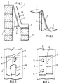
- a member 1 for incorporation in a cavity wall comprising a bridging portion 2 for bridging the cavity in the cavity wall, and a flange 3 adapted to be received between two courses of a first (outer) skin 4 of said wall, the bridging portion 2 comprising support means 5, adapted to abut with a second (inner) skin 6 of said wall.
- the bridging portion 2 may be a planar member, and may be constructed from a flexible material which may be substantially waterproof.
- An example of a suitable material is bitumenised P.V.C.
- One or more flanges 3 extend from the bridging portion, and the support means may be a planar member 5 which may for example comprise extensions of the bridging portion 2.
- the member 1 has two flanges 3, located one at the top (as viewed) and one at the bottom (as viewed) of the bridging portion 2.
- the flange or flanges 3 are adapted to be received between two courses of bricks of the respective skins 4, 6 of the cavity wall in which the member 1 is located, and for this reason they are substantially flat.
- each end of the member 1 may be provided with more than one flange 3, and each flange 3 may be any suitable shape providing it is capable of being received as stated above.
- the support means 5 may take the form of a protuberance, or "wing” 7 extending from the under side (in use) of the bridging portion 2. It will be apparent that the wing 7 serves to prevent collapse of the bridging portion 2, by abutting against the skin 6 of the cavity wall, and it will further be apparent that a variety of shapes of wing 7 may be employed. In the embodiment illustrated here, the wing 7 is shown as a planar triangle.
- wings 7 There may be a plurality of wings 7 as shown, a suitable configuration comprising two wings 7, spaced apart from one another and extending substantially parallel to one another (Fig. 2).
- the or each wing 7 may be formed integrally with the bridging portion 2, or may be formed separately and fixed in place by for example welding or glueing. There may also be a plate member 8 fixed to the underside (in use) of the bridging portion 2, and which provides additional support to the bridging portion 2.
- flanges 9 When two or more wings 7 are provided, they may include flanges 9, which may be used to cross-connect the wings 7 for added strength.
- the flanges 9 may extend from the outer (in use) edges 10 of the wings 7 and at substantially 90° thereto, and may in addition be provided with a cooperating tongue 11 and slit 12, to form an enclosure when the tongue is inserted through the slit 12, the tongue having an arrow-shaped head which has lateral shoulders for locating behind the material of the wing 7 containing the slit, whereby to lock the wings together.
- Fig. 4 shows an alternative with three tongues 11 and slits 12.
- the support means 5 may be provided with a strengthening member which may comprise a block made of polystyrene or wood or other suitable material.
- the strengthening member may be adapted to be fitted into the support means 5.
- the support means 5 comprises a strong enclosure as described, the strengthening member may be adapted to fit inside.
- the member 1 is positioned to bridge the cavity of a cavity wall, either at the end of a cavity tray or damp-proof-course (DPC) or at a join between two runs of DPC.
- DPC damp-proof-course
- the member 1 When the member 1 is for use at the end of a run of DPC, it may be provided additionally with an edge piece 15, extending upwardly (in use) from the bridging portion 2 and flange 3, as illustrated in Fig. 2.
- the edge piece 15 acts to prevent trapped moisture from running down the brickwork at the edge of the DPC.
- the member 1 be positioned in the cavity so that the bridging portion 2 slopes from one side to the other. This is most easily achieved by mounting the flange 3 in between courses of one of the skins (the outer one in use), and positioning the member 1 with the bridging portion 2 sloping upwards, to either abut against the other (the inner as considered in use) skin, or be received between two courses of it at a higher position. In either position, the bridging portion 2 is supported by the support means 5 which abuts with its free rear (in use) edge and the forward face of the inner skin 6 of the wall.
- a deformable locator 16 placed on the underside of the member 1, as shown in Fig. 5. This may take the form of a clip or strip, and serves to aid location of the member 1 in the cavity.
- a member 20 having support means 5 comprising a block of substantially rigid material 17 disposed in use, adjacent to the underside of the bridging portion 2 of the member 1 by flexible securing means 18, to provide support to the member 20 when pressure is applied thereto.
- member 20 which is provided with three locating flanges, 19, 19A, and 19B.
- the first locating flange 19 extends from the bridging portion 2 at substantially 90° thereto and substantially horizontally in use in the manner of a shelf or ledge upon which the support means 5 may be mounted by way of the securing means 18.
- a second locating flange 19A extends substantially downwardly from the bridging portion 2, and a third locating flange 19B also extends substantially downwardly from a point near the top (in use) of the bridging portion 2.
- the support means 5 in the form of a wedge-shaped polystyrene block 17 is located between the first and third locating flanges 19, 19B.
- the block 17 is held in place by the flexible securing means 18, which in the illustrated embodiment is a patch of flexible adhesive located between the block 17 and the first locating flange 19 and which may be exposed for use by removing a release paper.
- the member 20 illustrated in Figure 7 is closely similar to that of Figure 1, except that there are no locating flanges required, the block 17 being secured to the underside of the bridging portion 2 in this embodiment by flexible securing means 18 in the form of a flexible adhesive, as in Fig. 6.
- the member 20 of Fig. 6 or Fig. 7 may be assembled prior to insertion between the skins 4, 6 of the wall, by fixing the support means 17 in place as described.
- the member 20 is then located in the wall as shown with the flanges 3 being received between two courses of either one, or as illustrated both, skins 4, 6 of the cavity wall.
- the member 20 may be located in position in the wall first as described, and the support means may then be secured to the bridging portion 2.
- the member 20 can be used where there is a requirement for a member which can provide support for cavity trays and damp-proof courses, whilst retaining flexibility to accommodate movement in the surrounding brickwork.
- the water-excluding abilities of the member 20 are also enhanced particularly by the flange 19A which acts as a shield in deflecting water passing through the outer skin of the wall downwardly into the cavity, and thus away from the inner skin.
- the flange 19A thus acts as a drip lip, likewise the flange 19B acts as a drip or shield or stop deflecting any water passing up the bridging portion 2.
- the securing means 18 between the base of the block 17 and the flange 19 may comprise a mechanical fixing means, such as a screw, staple or rivet.
- Sections of DPC at a joint may be joined using a glue applied to the bridging portion 2 of the member 1 or 2, or alternatively, the bridging portion 2 may be supplied with an adhesive pad, with a covering which may be removed when it is desired to be used.
- the invention thus allows DPCs to be joined easily by providing a strong platform upon which pressure can be applied for bonding.
- the configuration of the member 1 allows it to be used to bridge cavities in cavity walls of varying width, where the wall has been poorly made, and also one size of member 1 may be used to bridge a range of cavity widths.
- one size of member 1 can be selected for use without needing to know the precise widths of cavities in the project.
- variations in width within a range can be accommodated. This accommodation is facilitated by the curves of the member 1 and the positioning and the support, allowing a standard angle of slope to be maintained, even when a cavity varies in width along its length.
- a member embodying invention as hereinbefore described with reference to the drawings is easy to manufacture and use, and is capable of accommodating variations in cavity width whilst maintaining a standard angle of slope, due to the configuration of its support. No fabrication is required on site.
Landscapes
- Engineering & Computer Science (AREA)
- Architecture (AREA)
- Physics & Mathematics (AREA)
- Electromagnetism (AREA)
- Civil Engineering (AREA)
- Structural Engineering (AREA)
- Building Environments (AREA)
Applications Claiming Priority (4)
| Application Number | Priority Date | Filing Date | Title |
|---|---|---|---|
| GB9404906A GB9404906D0 (en) | 1994-03-14 | 1994-03-14 | A member |
| GB9404906 | 1994-03-14 | ||
| GB9420819A GB9420819D0 (en) | 1994-10-14 | 1994-10-14 | A member |
| GB9420819 | 1994-10-14 |
Publications (1)
| Publication Number | Publication Date |
|---|---|
| EP0672802A1 true EP0672802A1 (de) | 1995-09-20 |
Family
ID=26304492
Family Applications (1)
| Application Number | Title | Priority Date | Filing Date |
|---|---|---|---|
| EP95301574A Withdrawn EP0672802A1 (de) | 1994-03-14 | 1995-03-10 | Bauelement |
Country Status (3)
| Country | Link |
|---|---|
| US (1) | US5819478A (de) |
| EP (1) | EP0672802A1 (de) |
| GB (1) | GB2287489B (de) |
Cited By (1)
| Publication number | Priority date | Publication date | Assignee | Title |
|---|---|---|---|---|
| GB2588649A (en) * | 2019-10-30 | 2021-05-05 | Acs Stainless Steel Fixings Ltd | Cavity tray system |
Families Citing this family (10)
| Publication number | Priority date | Publication date | Assignee | Title |
|---|---|---|---|---|
| GB2299817A (en) * | 1995-04-13 | 1996-10-16 | Triform Building Products Limi | Support member for cavity wall damp proof course |
| GB9618126D0 (en) | 1996-08-29 | 1997-01-08 | British Aerospace | Thruster pack for missile control |
| GB2335445B (en) * | 1998-03-19 | 2002-05-29 | Ronald Curtis Bayes | A building component |
| GB2424658B (en) * | 2005-03-31 | 2008-09-10 | Timloc Building Products Ltd | An acoustic cavity stop |
| US8046956B1 (en) * | 2006-12-01 | 2011-11-01 | Mitek Holdings, Inc. | Channeled masonry flashing |
| GB0713081D0 (en) * | 2007-07-05 | 2007-08-15 | Cavity Trays Ltd | Damp course |
| US9187946B2 (en) * | 2013-09-11 | 2015-11-17 | Advanced Architectural Products, Llc | Through-wall metal flashing having thermal breaks |
| US11549256B2 (en) | 2018-03-12 | 2023-01-10 | Scott W. Sander | Method and apparatus for sealing grout space |
| US10954669B2 (en) * | 2018-03-12 | 2021-03-23 | Scott W. Sander | Method and apparatus for sealing grout space |
| WO2023009792A1 (en) * | 2021-07-30 | 2023-02-02 | Berry Global, Inc. | Moisture barrier system |
Citations (2)
| Publication number | Priority date | Publication date | Assignee | Title |
|---|---|---|---|---|
| GB2239465A (en) * | 1989-12-29 | 1991-07-03 | Weldform Components Ltd | Cavity tray |
| GB2267518A (en) * | 1992-05-19 | 1993-12-08 | Halfen Fixing Systems Limited | Combined DPC and wall-tie |
Family Cites Families (5)
| Publication number | Priority date | Publication date | Assignee | Title |
|---|---|---|---|---|
| US4218856A (en) * | 1978-09-25 | 1980-08-26 | Irwin John W | Connector for sloped roof deck |
| GB2143874B (en) * | 1983-07-26 | 1986-05-29 | Knox Colin J M | Cavity wall damp-proof course |
| GB2189275B (en) * | 1986-04-15 | 1990-08-15 | Glidevale Building Prod | Cavity tray |
| GB2197889A (en) * | 1986-11-20 | 1988-06-02 | Ruberoid Building Products Ltd | Damp-proof course |
| US5437132A (en) * | 1993-11-12 | 1995-08-01 | Meyers; Robert D. | Roof and wall panel tiedown bracket and method |
-
1995
- 1995-02-28 US US08/395,760 patent/US5819478A/en not_active Expired - Fee Related
- 1995-03-10 GB GB9504886A patent/GB2287489B/en not_active Expired - Fee Related
- 1995-03-10 EP EP95301574A patent/EP0672802A1/de not_active Withdrawn
Patent Citations (2)
| Publication number | Priority date | Publication date | Assignee | Title |
|---|---|---|---|---|
| GB2239465A (en) * | 1989-12-29 | 1991-07-03 | Weldform Components Ltd | Cavity tray |
| GB2267518A (en) * | 1992-05-19 | 1993-12-08 | Halfen Fixing Systems Limited | Combined DPC and wall-tie |
Cited By (2)
| Publication number | Priority date | Publication date | Assignee | Title |
|---|---|---|---|---|
| GB2588649A (en) * | 2019-10-30 | 2021-05-05 | Acs Stainless Steel Fixings Ltd | Cavity tray system |
| GB2588649B (en) * | 2019-10-30 | 2021-11-10 | Acs Stainless Steel Fixings Ltd | Cavity tray system |
Also Published As
| Publication number | Publication date |
|---|---|
| GB2287489B (en) | 1998-07-08 |
| GB2287489A (en) | 1995-09-20 |
| GB9504886D0 (en) | 1995-04-26 |
| US5819478A (en) | 1998-10-13 |
Similar Documents
| Publication | Publication Date | Title |
|---|---|---|
| US5819478A (en) | Damp-proof course member | |
| FI117765B (fi) | Rakennuslevyjen saumausjärjestelmä | |
| US5240342A (en) | Variable angle joist support | |
| RU2606477C2 (ru) | Механическая фиксация панелей настила пола к язычку с нанесенным слоем клея | |
| US8752800B2 (en) | Board mount | |
| JPH10501857A (ja) | 連結された複数のフォーム・パネルを使用する絶縁コンクリート型枠 | |
| RU2373349C2 (ru) | Панель, в частности панель для пола | |
| CA2370896A1 (en) | Tilt-up concrete panel forming system | |
| CN1269857A (zh) | 可弯曲的混凝土模板 | |
| US5377463A (en) | Panel mounting | |
| US5009051A (en) | Clip construction for aligning siding sections | |
| US5060438A (en) | Method and apparatus for supporting a tile counter cap support strip | |
| EP0387043A1 (de) | Wandsturzprofil | |
| KR20050084158A (ko) | 클래딩 요소 | |
| EP0410692B1 (de) | Sturzprofilsystem | |
| US20030033771A1 (en) | House trim corner pieces and method of assembly | |
| US20060000174A1 (en) | Concrete expansion joint | |
| GB2299817A (en) | Support member for cavity wall damp proof course | |
| GB2193516A (en) | Damp proof strips or cavity trays with flashing attachment | |
| EP1127200B1 (de) | Verfahren zum verbinden von baublöcken | |
| JP3002820U (ja) | 天井下地ボード用目地支持材 | |
| GB2335445A (en) | A support for a cavity wall damp-proof course | |
| GB2372513A (en) | Damp proof course support | |
| US20080307730A1 (en) | Channel screed with fastening clips | |
| GB2197889A (en) | Damp-proof course |
Legal Events
| Date | Code | Title | Description |
|---|---|---|---|
| PUAI | Public reference made under article 153(3) epc to a published international application that has entered the european phase |
Free format text: ORIGINAL CODE: 0009012 |
|
| AK | Designated contracting states |
Kind code of ref document: A1 Designated state(s): BE DE ES FR IT NL |
|
| RIN1 | Information on inventor provided before grant (corrected) |
Inventor name: BAYES, RONALD CURTIS |
|
| 17P | Request for examination filed |
Effective date: 19960320 |
|
| RAP1 | Party data changed (applicant data changed or rights of an application transferred) |
Owner name: D. ANDERSON & SON LIMITED |
|
| 17Q | First examination report despatched |
Effective date: 19980120 |
|
| STAA | Information on the status of an ep patent application or granted ep patent |
Free format text: STATUS: THE APPLICATION IS DEEMED TO BE WITHDRAWN |
|
| 18D | Application deemed to be withdrawn |
Effective date: 19990727 |