EP0672355B1 - Method and apparatus for transporting filter rods - Google Patents
Method and apparatus for transporting filter rods Download PDFInfo
- Publication number
- EP0672355B1 EP0672355B1 EP95102810A EP95102810A EP0672355B1 EP 0672355 B1 EP0672355 B1 EP 0672355B1 EP 95102810 A EP95102810 A EP 95102810A EP 95102810 A EP95102810 A EP 95102810A EP 0672355 B1 EP0672355 B1 EP 0672355B1
- Authority
- EP
- European Patent Office
- Prior art keywords
- receiving means
- filter
- ejection zone
- conveying line
- conveyor
- Prior art date
- Legal status (The legal status is an assumption and is not a legal conclusion. Google has not performed a legal analysis and makes no representation as to the accuracy of the status listed.)
- Expired - Lifetime
Links
Images
Classifications
-
- A—HUMAN NECESSITIES
- A24—TOBACCO; CIGARS; CIGARETTES; SIMULATED SMOKING DEVICES; SMOKERS' REQUISITES
- A24C—MACHINES FOR MAKING CIGARS OR CIGARETTES
- A24C5/00—Making cigarettes; Making tipping materials for, or attaching filters or mouthpieces to, cigars or cigarettes
- A24C5/14—Machines of the continuous-rod type
- A24C5/31—Machines of the continuous-rod type with special arrangements coming into operation during starting, slowing-down or breakdown of the machine, e.g. for diverting or breaking the continuous rod
-
- A—HUMAN NECESSITIES
- A24—TOBACCO; CIGARS; CIGARETTES; SIMULATED SMOKING DEVICES; SMOKERS' REQUISITES
- A24C—MACHINES FOR MAKING CIGARS OR CIGARETTES
- A24C5/00—Making cigarettes; Making tipping materials for, or attaching filters or mouthpieces to, cigars or cigarettes
- A24C5/32—Separating, ordering, counting or examining cigarettes; Regulating the feeding of tobacco according to rod or cigarette condition
- A24C5/322—Transporting cigarettes during manufacturing
- A24C5/323—Transporting cigarettes during manufacturing pneumatically
-
- A—HUMAN NECESSITIES
- A24—TOBACCO; CIGARS; CIGARETTES; SIMULATED SMOKING DEVICES; SMOKERS' REQUISITES
- A24C—MACHINES FOR MAKING CIGARS OR CIGARETTES
- A24C5/00—Making cigarettes; Making tipping materials for, or attaching filters or mouthpieces to, cigars or cigarettes
- A24C5/32—Separating, ordering, counting or examining cigarettes; Regulating the feeding of tobacco according to rod or cigarette condition
- A24C5/322—Transporting cigarettes during manufacturing
- A24C5/328—Controlling means
Definitions
- the invention relates to a method according to the preamble of claim 1 and an apparatus according to the preamble of claim 7.
- the transport of the filters from filter production to further processing, for example in A filter attachment machine is usually carried out via a pneumatic delivery line on the input side to a transmitting station and on the output side to one with the magazine of the Processing machine connected receiving station is connected.
- the filter rods are rotating in successive shots Transfer conveyor (transmission drum) transaxially from a supply to a launch position brought, in which they are aligned with the pneumatic conveyor line.
- Transfer conveyor transmission drum
- the transfer conveyor continues to rotate, so that the filter rod in question at the same time is moved axially.
- the launch zone has an extension in the direction of rotation of the transfer conveyor, on the axial and cross-axial speed of the filters at launch is coordinated.
- the mouth of the pneumatic delivery line has been expanded accordingly and runs funnel-shaped towards the conveyor pipe (GB 2 068 325 A).
- This GB 2 068 325 A describes a pneumatic conveyor system that uses five filter manufacturing machines pneumatic conveyor lines with five magazine groups of filter processing machines connects.
- the conveyor lines connect two transmission stations in pairs above described type with a magazine of a processing machine.
- This system has one Series of sensors for detecting fault conditions and for generating fault signals on. This controls whether the sealing shoe or sealing block is opened, whether the Coupling disengages due to overload, whether the stock in the magazine is replenished, whether rods in enter the delivery line or whether there is a backlog in the delivery line.
- the invention has for its object a method and a device of the beginning to further improve the described type.
- the aim is to prevent sheared off Parts of a filter through the pneumatic conveyor line in the further production process get there and cause major interference.
- this object is achieved according to the invention solved in that the movement of the recording through the launch zone longitudinal axial movement of the filter from the intake into the delivery line is monitored and that an interference signal is generated if a filter within the recording in question has not completely left a predetermined time interval. When an interference signal occurs immediately the transverse axial movement of the conveyor stopped.
- the entry of a Admission to the launch zone and exit from the launch zone detected.
- the time of entry gives the start and the time of exit before the end of the time interval, in which a filter on launching its inclusion in the transfer conveyor must have left the error-free Transport the filter from the intake to the delivery line guarantee.
- the Method according to the invention when firing a filter successively the transition of the front and the rear End of filter from the intake in the delivery line and corresponding transition signals are formed, and there is an interference signal formed if not the times of both transition signals within the time interval specified for the launch lie.
- Claims 7 and 8 contain preferred arrangements of the monitoring means by which the longitudinal axial movement the filter from the recordings in the delivery line is monitored becomes.
- the arrangement of the monitoring means in the sealing block is particularly beneficial because it is very accurate in this way in the transition area between the rotating transmission drum and the mouth of the delivery line can be installed.
- the Claims 9 to 11 contain features of an embodiment of the Device with which the movement of the individual recordings through the launch zone and that for the axial movement the time interval available for the filter rods during firing is specified.
- Claims 12 to 15 relate to Features of the device proposed according to the invention, the enable advantageous use of the interference signals that occur. This makes shearing insufficiently shot Filter rods avoided and it is achieved that in the transition between the transfer conveyor and the mouth of the conveyor line stuck filters are automatically removed.
- the main advantage of the invention is that in disturbances occurring at the transmitting station can be detected immediately and they can be remedied automatically. It is through the return rotation of the transfer conveyor when it occurs Disorder ensured that a rotating between the Transfer conveyor and the stationary mouth of the line jammed filter is released and easily blown out can be. The quick detection and elimination of faults ensures a high transfer rate of the pneumatic Funding arrangement. This ensures that none are sheared off Filter parts get into the delivery line and the operation of the following machines. That will be with little technical effort achieved.
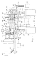
- FIG. 1 and 2 as an embodiment of the invention Conveying device shown has a transfer conveyor in the form of a front or transmission drum 1, the is provided with receiving troughs 2 for filter rods 3. With Suction holes 4 provided and limited by webs 6 Receiving troughs 2, also referred to as shots below, run parallel to the axis of rotation 7 of the conveyor drum 1 and are open radially outwards.
- the conveyor drum 1 is from a motor 8 via gears 9 and 11 by means of a shaft 12 continuously drivable in the direction of an arrow 13.
- the Conveyor drum 1 borders a filter rod magazine on its upper side 14 with front and rear boundary walls 16 and 17 where the recordings pass through a removal area 18.
- the recordings 2 are oriented one after the other axially parallel Open filter rods from magazine 14 and transport them them transversely axially in the direction of arrow 13 into one on the underside the delivery zone 1 arranged launch zone Z.
- This launch zone Z is aligned axially with one in a control ring 19 provided mouth 22 of a pneumatic conveyor line 21.
- the sealing block has one of the circular arc Path of the conveyor drum 1 adapted sealing surface 24th and extends along the circumference of the conveyor drum 1 over the shooting zone 2 adjacent to the shooting zone 2.
- the sealing block 23 in the employed state, is supported exclusively sealing at its two ends with its sealing surface 24 on two stationary arranged concentrically to the conveyor drum 1 Support bushings 19 and 26, the outer radius of the radius corresponds to the sealing surface 24, but is slightly larger than the outer radius of the conveyor drum 1. This gives a game and thus a non-contact employment between the drum peripheral surface formed by the webs 6 and the sealing surface 24 of the sealing block 23.
- the front support bush 19 is designed as a control ring, in which one with a vacuum source 27 connected and the front into one Control slot 28 opening vacuum line 29 runs.
- the Control slot 28 corresponds to in the conveyor drum 1 Axially parallel suction air bores 31 for the vacuum supply of the suction bores 4 in the receptacles 2.
- the shaft 12 of the conveyor drum 1 1 is through the support bushings 19th and 26 passed through and outside the support bushings in fixed Housing walls 32 and 33 mounted radially without play.
- the Support bushings 19 and 26 themselves carry a 34 via traverse members stationary mounting plate 36.
- the mounting plate takes two vertically arranged parallel guides 37 for the movement of the Sealing block 23 and two compressed air cylinders 38 for two compressed air pistons 39 for vertical up and down movement of the sealing block 23 on.
- the sealing block 23 is in two parts in the embodiment shown educated. It consists of an external shape the conveyor drum 1 adapted sealing body 41 and a support body 42.
- the support body 42 is also a supply plate in which one with a pressure source 43 connected compressed air line 44 runs.
- a Cross bore 46 in the sealing body 41 and control slots 47 in a control flange 48 of the conveyor drum 1 is provided.
- the Conveyor drum 1 has a separate one for each receptacle 2 Control slot 47 on that with an axially parallel Bore 49 is connected.
- the compressed air comes out of the Pressure source 43 via a connecting line 51, through the compressed air line 44, the transverse bore 46 and the control slot 47, that of the receptacle 2 that is currently in the launch zone Z is assigned through the axially parallel bore 49 as a shot or Conveying air into the mouth 22 of the pneumatic conveying line aligned recording 2.
- a sensor 52 in the sealing body 41 of the sealing block 23 for example in the form of a reflection light barrier, arranged, the movement of a filter rod 3 during the Shot in the delivery line 21 detected.
- This sensor 52 5 is connected to a control arrangement 53, which can be the machine control.
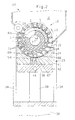
- the conveyor drum 1 are, as in Figure 2 schematically as an embodiment shown, two position detectors 54 and 56, for example in the form of proximity initiators, which can also be integrated in the sealing block Position detectors 54 and 56 are also in accordance with FIG Control arrangement 53 connected.
- Figure 1 shows in the area of the inlet end of the conveyor line 21 a compressed air connection connected to the compressed air source 57, for introducing blow-back air into the delivery line serves.
- Figure 1 shows the sealing block in its working position, in the its sealing surface 24 rests on the support bushings 19 and 26 and thereby the recordings 2 located in the launch zone Z Seals conveyor drum 1 to the outside.
- a dashed line Line 58 is the bottom position, the maintenance position, of the Sealing block 23 indicated.
- a cleaning nozzle 59 aligned with the pressure source 43 connected is.
- the conveying air connection 51 is the Compressed air connection 57 and the cleaning nozzle 59 via valves 61 to 63 connected to the compressed air source, so that the corresponding Compressed air supply is controllable.
- electrical connection lines in the scheme of Figure 5 with a simple line and pneumatic lines are marked with double lines.
- the free ending arrows at valves 61 to 63 make the connections to the Consumers 51, 57 and 59.
- the sealing block becomes 23 from its lower, for example for cleaning reasons Maintenance position 58 raised to its working position, in which its sealing surface, as shown in FIGS. 1 and 2, bears sealingly against the support bushings 19 and 26.
- the air cylinder 38 actuated so that the pressure stamp 39th move the sealing block 23 upwards against the support bushings.
- the Switzerlandtraversen 34 catch the support bushings 19 and 26 applied pressure and bending forces and brace the System in itself. Because of the smaller drum diameter Conveyor drum 1 remains between the peripheral surface of the Conveyor drum 1 and the sealing block 23 a defined free space, so that smooth and therefore wear-free operation of the Conveyor device is possible.
- the filter rods 3 are in the receptacles 2 from the conveyor drum 1 the removal area 18 transferred to the launch zone Z, in which align the filter rods with the delivery line.
- the filter rods 3 continues to rotate, the filter rods are simultaneously thus also moved axially.
- Figure 2 shows schematically a section approximately along the line B-B of Figure 1.
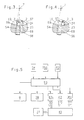
- Figures 3 and 4 show enlarged sections of the same cross-section in the area of the launch zone Z.
- the section through the conveyor drum 1 is on two places have broken out so that there is a view of the Front side of the support bush or the control ring 19 is free.
- a piece of the control slot becomes in the upper part 28 visible, the for supplying the suction air with the Suction air holes 31 in the conveyor drum 1 corresponds.
- in the lower broken out area of the drum is the one in the Support bushing 19 provided opening 67 of the pneumatic Recognize the delivery line.
- the figure is dashed the receptacle just aligned with this mouth opening 67 2 of the conveyor indicated, in which one in the delivery line filter rod to be fired can be seen.
- the right dashed line 68 the rear flank surface of the preceding web and the left dashed line 69 the front flank surface of the subsequent web 6.
- the Firing a filter rod 3 from a receptacle 2 of the conveyor can begin when the recording is relative to the mouth opening 67 of the pneumatic delivery line that shown in Figure 3 relative position. At that moment, cursed the filter rod 3 with the mouth opening and can freely from the Recording 2 can be moved into the mouth opening 67.
- the longitudinal axial Movability of a filter rod 3 ends when the recording 2 of the rotating conveyor relative to the mouth opening 67 has reached the position shown in FIG. 4, in which a filter rod that has not yet completely left the recording has between the rotating conveyor drum and the mouth the stationary delivery line is pinched.
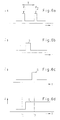
- the two initiators 54 and 56 specify a time interval T (FIG. 6), in which a receptacle 2 is aligned with the opening 67 of the conveying line during the rotation of the conveying drum 1 so that a longitudinally axial movement of the filter rod into the conveying line is possible.
- the initiators are set on the front flank surface 69 of the webs 6. When this flank surface 69 is detected by the initiator 54 at time t1, which is shown in FIG. 3, it forms a first position signal P1, which indicates that a receptacle 2 with the filter rod 3 conveyed therein is now aligned with the opening 67 of the delivery line and the launch can take place.
- the same flank surface 69 is detected by the second initiator 56 at time t 2 , it forms a second position signal P 2 , which indicates that the recording has now emerged from the firing zone Z to such an extent that a further longitudinal axial movement of the filter rod is no longer possible .
- time t 1 of the first and time t 2 of the second position signal lies the time interval T (FIG. 6a) in which the longitudinal axial movement of the filter from the holder into the delivery line is possible.
- the sensor detects 52 ( Figure 1), the transition from the transversely axially moving receptacle 2 to the stationary mouthpiece 22 of the Delivery line 21 is assigned, the longitudinal axial movement of the Filters 3 at launch. It creates the beginning and the end the filter passage through the detection range of the sensor indicating transition signal S, its timing and duration checked by the control arrangement 53 relative to the time interval T. becomes. The normal case is shown in FIG. 6b and in FIG. that the 3 operation runs smoothly.
- the longitudinal axial Filter movement from the receptacle past the sensor 52 into the Delivery line, which is indicated by the transition signal S lies fully in the time interval T; the filter leaves the recording completely while the shot passes through the launch zone Z.
- Figures 6c and 6d show the signal curves in the event of a fault.
- transition signal S of the sensor 52 is not completely in predetermined time interval T ( Figure 6c), it means that the filter is still in the transition area between the recording and the mouth 22 of the delivery line 21 is when the Recording leaves the launch zone Z (see also Figure 4).
- the control arrangement 53 emits an interference signal which momentarily stops the drum drive 8 and the conveyor drum 1 before the drum and Clogged filter mouth of the delivery line is sheared and filter fragments get into the delivery line.
- the control arrangement 53 controls the motor 3, whereby the Transmitter drum is turned back by a small angle and releases the jammed filter. If the filter is OK, he can now continue from the recording flowing conveying air can be moved into the conveying line 21 ( Figure 6c), which eliminates the problem quickly.
- the control arrangement switches 53 the valves 61 and 62, so switches the Conveying air from and the blow-back air through port 57, so that the filter is moved back into the holder.
- the sealing block 23 is moved into the lowered maintenance position 58 and its sealing surface 24 by means of a compressed air flow from the Blown cleaning nozzle 59, with the filter blown out be dropped into a collecting container, not shown.
- the Actuation of the sealing block drives 38 and switching the Cleaning air valves 63 are also dependent from the interference signal by the control arrangement 53.
Abstract
Description
Die Erfindung betrifft ein Verfahren nach dem Oberbegriff des Anspruchs 1 und eine Vorrichtung
nach dem Oberbegriff des Anspruchs 7.The invention relates to a method according to the preamble of
Der Transport der Filter von der Filterherstellung zur Weiterverarbeitung beispielsweise in
einer Filteransetzmaschine erfolgt in der Regel über eine pneumatische Förderleitung, die
eingangsseitig an eine Sendestation und ausgangsseitig an eine mit dem Magazin der
Weiterverarbeitungsmaschine verbundene Empfangsstation angeschlossen ist. In der
Sendestation werden die Filterstäbe in aufeinanderfolgenden Aufnahmen eines rotierendes
Überführungsförderers (Sendetrommel) queraxial aus einem Vorrat in eine Abschußposition
gebracht, in der sie mit der pneumatischen Förderleitung fluchten. In der Abschußposition
werden sie mittels Druckluft längsaxial in die Förderleitung bewegt, in der sie dann
pneumatisch zur Empfangsstation bei der Weiterverarbeitungsmaschine gefördert werden.
Während der längsaxialen Bewegung eines Filterstabes aus der Aufnahme in die Förderleitung
rotiert der Überführungsförderer weiter, so daß der betreffende Filterstab gleichzeitig
queraxial bewegt wird. Um ein Einklemmen der Filter zwischen dem rotierenden Überführungsförderer
und der stationären Mündung der pneumatischen Förderleitung zu vermeiden,
hat die Abschußzone in Umlaufrichtung des Überführungsförderers eine Ausdehnung,
die auf die axiale und die queraxiale Geschwindigkeit der Filter beim Abschuß
abgestimmt ist. Die Mündung der pneumatischen Förderleitung ist dementsprechend aufgeweitet
und läuft trichterförmig auf das Förderrohr zu (GB 2 068 325 A). Diese GB 2 068
325 A beschreibt ein pneumatisches Fördersystem, das fünf Filterherstellmaschinen über
pneumatische Förderleitungen mit fünf Magazingruppen von Filterverarbeitungsmaschinen
verbindet. Die Förderleitungen verbinden dabei paarweise zwei Sendestationen der oben
beschriebenen Art mit einem Magazin einer Verarbeitungsmaschine. Dadurch wird ein
Magazin jeweils über zwei Förderleitungen beschickt, was eine erhebliche Verbesserung
der Versorgungssicherheit der Magazine mit Filtern bedeutet. Dieses System weist eine
Reihe von Sensoren zum Erfassen von Fehlerzuständen und zum Erzeugen von Fehlersignalen
auf. Damit wird kontrolliert, ob der Dichtschuh oder Dichtklotz geöffnet wird, ob die
Kupplung wegen Überlastung ausrückt, ob der Vorrat im Magazin ergänzt wird, ob Stäbe in
die Förderleitung eintreten oder ob in der Förderleitung ein Rückstau entsteht.The transport of the filters from filter production to further processing, for example in
A filter attachment machine is usually carried out via a pneumatic delivery line
on the input side to a transmitting station and on the output side to one with the magazine of the
Processing machine connected receiving station is connected. In the
Transmitting station, the filter rods are rotating in successive shots
Transfer conveyor (transmission drum) transaxially from a supply to a launch position
brought, in which they are aligned with the pneumatic conveyor line. In the launch position
they are moved longitudinally axially into the delivery line using compressed air, in which they are then
pneumatically conveyed to the receiving station at the processing machine.
During the axial movement of a filter rod from the holder into the delivery line
the transfer conveyor continues to rotate, so that the filter rod in question at the same time
is moved axially. To pinch the filter between the rotating transfer conveyor
and to avoid the stationary mouth of the pneumatic delivery line,
the launch zone has an extension in the direction of rotation of the transfer conveyor,
on the axial and cross-axial speed of the filters at launch
is coordinated. The mouth of the pneumatic delivery line has been expanded accordingly
and runs funnel-shaped towards the conveyor pipe (
Bei ordnungsgemäßem Betrieb einer Sendestation hat ein Filter seine Aufnahme im Überführungsförderer verlassen, wenn diese Aufnahme sich aus der Abschußzone hinausbewegt, so daß der Überführungsförderer die nächste Aufnahme ungehindert in die Abschußzone bewegen kann.When a transmitting station is operating properly, a filter is accommodated in the transfer conveyor leave when this shot moves out of the launch zone, so that the transfer conveyor unhindered the next intake in the launch zone can move.
Bleibt ein Filter beim Abschuß zurück, so daß er seine Aufnahme nicht vollständig verläßt,
während sie in der Abschußzone liegt, so kommt es zur Kollision, bei der der Filter
zwischen der stationären Mündung der Förderleitung und dem rotierenden Überführungsförderer
eingeklemmt wird. Da sich der Überführungsförderer mit hoher Geschwindigkeit
bewegt und da er stirnseitig zur stationären Mündung der Förderleitung eine hohe Scherkraft
auf den eingeklemmten Filter ausübt, kann dieser teilweise abgeschert werden, wobei
ein Teil des Filters in die Förderleitung gelangt und der andere in der Aufnahme des Überführungsförderers
zurückbleibt. Das führt zu einer Störung, die bei stillstehender Einrichtung
behoben werden muß. Die GB 2 068 325 spricht dieses Problem weder an noch bietet
sie eine Lösung dafür.If a filter remains when it is fired, so that it does not completely leave its holder,
while it is in the launch zone, the filter collides
between the stationary mouth of the conveyor line and the rotating transfer conveyor
is pinched. Because the transfer conveyor is moving at high speed
moves and because it has a high shear force on the face of the stationary mouth of the delivery line
exerted on the pinched filter, this can be partially sheared off, whereby
part of the filter gets into the conveyor line and the other in the receiving of the transfer conveyor
remains. This leads to a malfunction that occurs when the facility is at a standstill
must be remedied.
Der Erfindung liegt die Aufgabe zugrunde, ein Verfahren und eine Vorrichtung der eingangs beschriebenen Art weiter zu verbessern. Insbesondere soll verhindert werden, daß abgescherte Teile eines Filters durch die pneumatische Förderleitung in den weiteren Produktionsprozeß gelangen und dort größere Störungen verursachen.The invention has for its object a method and a device of the beginning to further improve the described type. In particular, the aim is to prevent sheared off Parts of a filter through the pneumatic conveyor line in the further production process get there and cause major interference.
Bei einem Verfahren der eingangs angegebenen Art wird diese Aufgabe erfindungsgemäß dadurch gelöst, daß während der Bewegung der Aufnahme durch die Abschußzone die längsaxiale Bewegung des Filters aus der Aufnahme in die Förderleitung überwacht wird und daß ein Störsignal erzeugt wird, sofern ein Filter die betreffende Aufnahme innerhalb eines vorgegebenen Zeitintervalls nicht vollständig verlassen hat. Beim Auftreten eines Störsignals wird sofort automatisch die queraxiale Bewegung des Förderers angehalten. In a method of the type specified at the outset, this object is achieved according to the invention solved in that the movement of the recording through the launch zone longitudinal axial movement of the filter from the intake into the delivery line is monitored and that an interference signal is generated if a filter within the recording in question has not completely left a predetermined time interval. When an interference signal occurs immediately the transverse axial movement of the conveyor stopped.
In weiterer Fortbildung der Erfindung werden der Eintritt einer Aufnahme in die Abschußzone und ihr Austritt aus der Abschußzone erfaßt. Der Zeitpunkt des Eintritts gibt den Beginn und der Zeitpunkt des Austritts das Ende des Zeitintervalls vor, in welchem ein Filter beim Abschuß seine Aufnahme in den Überführungsförderer verlassen haben muß, um den fehlerfreien Transport des Filters aus der Aufnahme in die Förderleitung zu gewährleisten. Gemäß einer bevorzugten Ausführungsform des Verfahrens nach der Erfindung werden beim Abschuß eines Filters nacheinander der Übergang des vorderen und des hinteren Filterendes aus der Aufnahme in die Förderleitung erfaßt und entsprechende Übergangssignale gebildet, und es wird ein Störsignal gebildet, wenn nicht die Zeitpunkte beider Übergangssignale innerhalb des für den Abschuß vorgegebenen Zeitintervalls liegen. Dies ist eine besonders praktikable Methode, um die längsaxiale Bewegung des Filters beim Abschuß in die Förderleitung mit seiner queraxialen Bewegung durch die Abschußzone zu vergleichen und auftretende Fehler und entstehende Störungen sofort zu erfassen. Das Anhalten des Förderers geschieht, bevor ein nicht vollständig in die Förderleitung eingetretener Filter von der rotierenden Sendetrommel abgeschert werden kann. Um einen eingeklemmten Filter freizugeben, wird die Sendetrommel nach dem Anhalten vorzugsweise etwas zurückgedreht. Der Filter kann dann leicht aus dem Übergangsbereich entfernt werden. So wird vermieden, daß Filterfragmente durch die Förderleitung in den weiteren Produktionsprozeß gelangen. Die Ansprüche 4 und 5 enthalten Maßnahmen zur Störungsbeseitigung, mit denen erreicht wird, daß beim Abschuß hängengebliebene Filter schnell und sicher aus der Fördereinrichtung entfernt werden.In a further development of the invention, the entry of a Admission to the launch zone and exit from the launch zone detected. The time of entry gives the start and the time of exit before the end of the time interval, in which a filter on launching its inclusion in the transfer conveyor must have left the error-free Transport the filter from the intake to the delivery line guarantee. According to a preferred embodiment of the Method according to the invention when firing a filter successively the transition of the front and the rear End of filter from the intake in the delivery line and corresponding transition signals are formed, and there is an interference signal formed if not the times of both transition signals within the time interval specified for the launch lie. This is a particularly practical way to the longitudinal axial movement of the filter when fired into the delivery line with its transverse axial movement through the launch zone to compare and occurring errors and arising Record faults immediately. The Stopping the conveyor happens before one is not complete filter that entered the delivery line from the rotating one Transmission drum can be sheared off. To get a jammed To release filters, the transmitter drum will stop after stopping preferably turned back a little. The filter can then be easily be removed from the transition area. This will avoid that filter fragments through the delivery line in the further Production process. Claims 4 and 5 contain Troubleshooting measures to achieve that filters stuck when fired quickly and safely be removed from the conveyor.
Bei einer Vorrichtung der eingangs angegebenen Art wird die
der Erfindung zugrunde liegende Aufgabe
mit den kennzeichnenden Merkmalen von Anspruch 6 gelöst.In a device of the type specified in the
object underlying the invention
solved with the characterizing features of
Fortbildungen und vorteilhafte Ausgestaltungen der Vorrichtung
nach der Erfindung sind in den Unteransprüchen 7 bis 15 angegeben.
Dabei enthalten die Ansprüche 7 und 8 bevorzugte Anordnungen
der Überwachungsmittel, mit denen die längsaxiale Bewegung
der Filter aus den Aufnahmen in die Förderleitung überwacht
wird. Die Anordnung der Überwachungsmittel im Dichtklotz
ist besonders vorteilhaft, weil sie auf diese Weise sehr genau
in den Übergangsbereich zwischen der rotierenden Sendetrommel
und der Mündung der Förderleitung eingebaut werden kann. Die
Ansprüche 9 bis 11 enthalten Merkmale einer Ausgestaltung der
Vorrichtung, mit der die Bewegung der einzelnen Aufnahmen
durch die Abschußzone erfaßt und das für die längsaxiale Bewegung
der Filterstäbe beim Abschuß zur Verfügung stehende Zeitintervall
vorgegeben wird. Die Ansprüche 12 bis 15 betreffen
Merkmale der erfindungsgemäß vorgeschlagenen Vorricntung, die
eine vorteilhafte Nutzung der auftretenden Störsignale ermöglichen.
Damit wird das Abscheren unzulänglich abgeschossener
Filterstäbe vermieden und es wird erreicht, daß im Übergang
zwischen dem Überführungsförderer und der Mündung der Förderleitung
steckengebliebene Filter automatisch entfernt werden.Training and advantageous refinements of the device
according to the invention are specified in
Der wesentliche Vorteil der Erfindung besteht darin, daß in der Sendestation entstehende Störungen sofort erfaßt werden und ihre Behebung automatisch erfolgen kann. Dabei ist durch die Rückdrehung des Überführungsförderers bei einer auftretenden Störung dafür gesorgt, daß ein zwischen dem rotierenden Überführungsförderer und der stationären Mündung der Leitung eingeklemmter Filter freigegeben wird und ohne Mühe ausgeblasen werden kann. Die schnelle Störungserkennung und -beseitigung gewährleistet eine hohe Transferrate der pneumatischen Förderanordnung. Dabei ist sichergestellt, daß keine abgescherten Filterteile in die Förderleitung gelangen und den Betrieb der nachfolgenden Maschinen stören. Das wird mit geringem technischem Aufwand erreicht. The main advantage of the invention is that in disturbances occurring at the transmitting station can be detected immediately and they can be remedied automatically. It is through the return rotation of the transfer conveyor when it occurs Disorder ensured that a rotating between the Transfer conveyor and the stationary mouth of the line jammed filter is released and easily blown out can be. The quick detection and elimination of faults ensures a high transfer rate of the pneumatic Funding arrangement. This ensures that none are sheared off Filter parts get into the delivery line and the operation of the following machines. That will be with little technical effort achieved.
Die Erfindung wird nun anhand der Zeichnung näher erläutert. Es zeigen
Figur 1- in einer teilweise geschnittenen Seitenansicht ein Ausführungsbeispiel einer Vorrichtung nach der Erfindung,
Figur 2- einen Schnitt in der Ebene B-B der
Figur 1, Figuren 3 und 4- zwei verschiedene Positionen einer Aufnahme des Überführungsförderers in der Abschußzone,
- Figur 5
- ein Schema der Steuerungsanordnung und der Druckluftversorgung der Vorrichtung nach der Erfindung und
Figur 6- verschiedene Signalverläufe der Sensoren bzw. Detektoren der Vorrichtung.
- Figure 1
- in a partially sectioned side view an embodiment of a device according to the invention,
- Figure 2
- 2 shows a section in the plane BB of FIG. 1,
- Figures 3 and 4
- two different positions of a transfer conveyor intake in the launch zone,
- Figure 5
- a diagram of the control arrangement and the compressed air supply of the device according to the invention and
- Figure 6
- different signal profiles of the sensors or detectors of the device.
Die in den Figuren 1 und 2 als Ausführungsbeispiel der Erfindung
dargestellte Fördervorrichtung weist einen Überführungsförderer
in Gestalt einer Vorder- oder Sendetrommel 1 auf, die
mit Aufnahmemulden 2 für Filterstäbe 3 versehen ist. Die mit
Saugbohrungen 4 versehenen sowie von Stegen 6 begrenzten
Aufnahmemulden 2, im folgenden auch kurz Aufnahmen genannt,
verlaufen parallel zur Drehachse 7 der Fördertrommel 1 und
sind radial nach außen offen. Die Fördertrommel 1 ist von
einem Motor 8 über Zahnräder 9 und 11 mittels einer Welle 12
in Richtung eines Pfeiles 13 kontinuierlich antreibbar. Die
Fördertrommel 1 grenzt an ihrer Oberseite an ein Filterstabmagazin
14 mit vorderen und hinteren Begrenzungswänden 16 und
17 an, wo die Aufnahmen einen Entnahmebereich 18 durchlaufen.
Hier nehmen die Aufnahmen 2 nacheinander achsparallel orientierte
Filterstäbe aus dem Magazin 14 auf und transportieren
sie queraxial in Pfeilrichtung 13 in eine an der Unterseite
der Fördertrommel 1 angeordnete Abschußzone Z. Diese Abschußzone
Z fluchtet längsaxial mit einer in einem Steuerring 19
vorgesehenen Mündung 22 einer pneumatischen Förderleitung 21.The in Figures 1 and 2 as an embodiment of the invention
Conveying device shown has a transfer conveyor
in the form of a front or
Im Bereich der Abschußzone Z sind die Aufnahmen 2 der Fördertrommel
1 mit einem Dichtklotz 23 radial nach außen zur Umgebung
hin verschlossen. Der Dichtklotz weist eine der kreisbogenförmigen
Bahn der Fördertrommel 1 angepaßte Dichtfläche 24
auf und erstreckt sich am Umfang der Fördertrommel 1 entlang
über die der Abschußzone Z benachbarten Aufnahmen 2 hinweg. Im
angestellten Zustand stützt sich der Dichtklotz 23 ausschließlich
an seinen beiden Enden mit seiner Dichtfläche 24 dichtend
an zwei konzentrisch zur Fördertrommel 1 angeordneten ortsfesten
Stützbuchsen 19 und 26 ab, deren Außenradius dem Radius
der Dichtfläche 24 entspricht, jedoch geringfügig größer ist
als der Außenradius der Fördertrommel 1. Auf diese Weise ergibt
sich ein Spiel und damit eine berührungsfreie Anstellung zwischen
der durch die Stege 6 gebildeten Trommelumfangsfläche
und der Dichtfläche 24 des Dichtklotzes 23. Die vordere Stützbuchse
19 ist als Steuerring ausgebildet, in welchem eine mit
einer Unterdruckquelle 27 verbundene und stirnseitig in einen
Steuerschlitz 28 mündende Unterdruckleitung 29 verläuft. Der
Steuerschlitz 28 korrespondiert mit in der Fördertrommel 1
achsparallel verlaufenden Saugluftbohrungen 31 für die Unterdruckversorgung
der Saugbohrungen 4 in den Aufnahmen 2.In the area of the launch zone Z are the
Die Welle 12 der Fördertrommel 1 1 ist durch die Stützbuchsen 19
und 26 hindurchgeführt und außerhalb der Stützbuchsen in ortsfesten
Gehäusewänden 32 und 33 radial spielfrei gelagert. Die
Stützbuchsen 19 und 26 selbst tragen über Zugtraversen 34 eine
stationäre Montageplatte 36. Die Montageplatte nimmt zwei
vertikal angeordnete Parallelführungen 37 für die Bewegung des
Dichtklotzes 23 sowie zwei Druckluftzylinder 38 für zwei Druckluftkolben
39 zur vertikalen Auf- und Abbewegung des Dichtklotzes
23 auf.The
Der Dichtklotz 23 ist im gezeigten Ausführungsbeispiel zweiteilig
ausgebildet. Er besteht aus einem an die äußere Form
der Fördertrommel 1 angepaßten Dichtkörper 41 und einem Tragkörper
42. Der Tragkörper 42 ist gleichzeitig als Versorgungsplatte
ausgebildet, in welcher eine mit einer Druckquelle 43
verbundene Druckluftleitung 44 verläuft. Zum Einleiten der
Druckluft aus der Druckluftleitung 44 in die in der Abschußzone
Z befindliche Aufnahme 2 der Fördertrommel 1 sind eine
Querbohrung 46 im Dichtkörper 41 sowie Steuerschlitze 47 in
einem Steuerflansch 48 der Fördertrommel 1 vorgesehen. Die
Fördertrommel 1 weist für jede Aufnahme 2 einen separaten
Steuerschlitz 47 auf, der mit dieser über eine achsparallele
Bohrung 49 verbunden ist. Die Druckluft gelangt also aus der
Druckquelle 43 über eine Anschlußleitung 51, durch die Druckluftleitung
44, die Querbohrung 46 und den Steuerschlitz 47,
der der gerade in der Abschußzone Z befindlichen Aufnahme 2
zugeordnet ist, durch die achsparallele Bohrung 49 als Schußoder
Förderluft in die zur Mündung 22 der pneumatischen Förderleitung
ausgerichtete Aufnahme 2.The sealing
Im Übergangsbereich zwischen der stromabwärtigen Stirnseite
der rotierenden Fördertrommel 1 und dem stationären Steuerring
19 ist im Dichtkörper 41 des Dichtklotzes 23 ein Sensor 52
beispielsweise in Gestalt einer Reflexionslichtschranke,
angeordnet, der die Bewegung eines Filterstabes 3 während des
Abschusses in die Förderleitung 21 erfaßt. Dieser Sensor 52
ist, wie Figur 5 zeigt, mit einer Steueranordnung 53 verbunden,
bei der es sich um die Maschinensteuerung handeln kann.In the transition area between the downstream end face
the
Der Fördertrommel 1 sind, wie in Figur 2 schematisch als Ausführungsbeispiel
dargestellt, zwei Lagedetektoren 54 und 56,
beispielsweise in Gestalt von Näherungsinitiatoren, zugeordnet,
die ebenfalls im Dichtklotz integriert sein können Die
Lagedetektoren 54 und 56 sind gemäß Figur 5 ebenfalls an die
Steueranordnung 53 angeschlossen.The
Figur 1 zeigt im Bereich des Eintrittsendes der Förderleitung
21 einen mit der Druckluftquelle verbundenen Druckluftanschluß
57, der zum Einleiten von Rückblasluft in die Förderleitung
dient.Figure 1 shows in the area of the inlet end of the conveyor line
21 a compressed air connection connected to the
Figur 1 zeigt den Dichtklotz in seiner Arbeitsposition, in der
seine Dichtfläche 24 an den Stützbuchsen 19 und 26 anliegt und
dadurch die in der Abschußzone Z befindlichen Aufnahmen 2 der
Fördertrommel 1 nach außen abdichtet. Mit einer gestrichelten
Linie 58 ist die untere Position, die Wartungsposition, des
Dichtklotzes 23 angedeutet. Auf die Dichtfläche des in die
Wartungsposition abgesenkten Dichtklotzes ist eine Reinigungsdüse
59 ausgerichtet, die ebenfalls mit der Druckquelle 43
verbunden ist.Figure 1 shows the sealing block in its working position, in the
its
Wie die Figur 5 zeigt, sind der Förderluftanschluß 51, der
Druckluftanschluß 57 und die Reinigungsdüse 59 über Ventile 61
bis 63 mit der Druckluftquelle verbunden, damit die entsprechende
Druckluftzufuhr steuerbar ist. Es sei darauf hingewiesen,
daß elektrische Verbindungsleitungen in dem Schema der
Figur 5 mit einer einfachen Linie und pneumatische Leitungen
mit Doppellinien gekennzeichnet sind. Die frei endenden Pfeile
an den Ventilen 61 bis 63 stellen die Verbindungen zu den
Verbrauchern 51, 57 und 59 dar.As FIG. 5 shows, the conveying
Wird die Fördervorrichtung in Gang gesetzt, so wird der Dichtklotz
23 aus seiner beispielsweise aus Reinigungsgründen unteren
Wartungsposition 58 in seine Arbeitsposition angehoben,
in der seine Dichtfläche, wie in den Figuren 1 und 2 gezeigt,
an den Stützbuchsen 19 und 26 dichtend anliegt. Hierzu werden
die Druckluftzylinder 38 betätigt, so daß die Druckstempel 39
den Dichtklotz 23 gegen die Stützbuchsen aufwärts bewegen. Die
Zugtraversen 34 fangen dabei die auf die Stützbuchsen 19 und
26 ausgeübten Druck- und Biegekräfte auf und verspannen das
System in sich. Wegen des geringeren Trommeldurchmessers der
Fördertrommel 1 verbleibt dabei zwischen der Umfangsfläche der
Fördertrommel 1 und dem Dichtklotz 23 ein definierter Freiraum,
so daß ein reibungs- und damit verschleißfreier Betrieb der
Fördervorrichtung möglich ist.If the conveyor device is started, the sealing block becomes
23 from its lower, for example for cleaning
Während des Betriebs übernimmt die über die Welle 12 mit konstanter
Drehzahl angetriebene Fördertrommel 1 in dem Entnahmebereich
18 Filterstäbe 3 aus dem Magazin 14 in ihre Aufnahmemulden
2, in denen sie mit der durch die Saugluftbohrungen 4,
die achsparallelen Bohrungen 31, den Steuerschlitz 28, die
Unterdruckleitung 29 von der Unterdruckquelle 27 angelegten
Saugluft festgehalten werden. Treten die achsparallelen Bohrungen
31 der Fördertrommel 1 bei der Drehung in Förderrichtung
13 aus dem Winkelbereich des Steuerschlitzes 28 aus, so
bewirkt die Fliehkraft, daß die Filterstäbe sich an die äußere
Begrenzung der Aufnahmen 2 anlegen und an dieser entlang bewegt
werden. Diese äußere Begrenzung wird oberhalb des Dichtklotzes
von einer Abdeckplatte 64 und im Bereich des Dichtklotzes von
dessen Dichtfläche 24 gebildet. In der Darstellung der Figur 2
sind nur in den Aufnahmen Filter 3 dargestellt, während die im
Vorrat 14 enthaltenen Filter weggelassen wurden. Die Filterstäbe
3 werden in den Aufnahmen 2 von der Fördertrommel 1 aus
dem Entnahmebereich 18 in die Abschußzone Z überführt, in
welcher die Filterstäbe mit der Förderleitung fluchten. Fluchtet
der Filterstab mit der pneumatischen Förderleitung 21 bzw.
mit deren stationärer Mündung 22, so wird aus der Druckluftquelle
43 durch die Leitungen 51 und 44 sowie durch die Querbohrung
46 und den betreffenden Steuerschlitz 47 Druckluft zu
der mit der Förderleitung fluchtenden Aufnahme 2 zugeführt,
welche den darin befindlichen Filterstab 3 in Richtung eines
Pfeiles 66 axial aus der Aufnahme in die Förderleitung bewegt.
Da sich die Fördertrommel während dieser längsaxialen Bewegung
der Filterstäbe 3 weiterdreht, werden die Filterstäbe gleichzeitig
also auch queraxial bewegt. Um ihnen dennoch einen
störungsfreien Eintritt in die Förderleitung zu ermöglichen,
ist die Mündung 22 der Förderleitung 21 in Richtung der queraxialen
Bewegung aufgeweitet, was in den Figuren 2 bis 4 erkennbar
ist.During operation, it takes over the
Figur 2 zeigt schematisch einen Schnitt etwa entlang der Linie B-B der Figur 1. Die Figuren 3 und 4 zeigen vergrößerte Ausschnitte desselben Querschnitts im Bereich der Abschußzone Z. Figure 2 shows schematically a section approximately along the line B-B of Figure 1. Figures 3 and 4 show enlarged sections of the same cross-section in the area of the launch zone Z.
In der Figur 2 ist der Schnitt durch die Fördertrommel 1 an
zwei Stellen ausgebrochen, so daß dort der Blick auf die
Stirnseite der Stützbuchse bzw. des Steuerrings 19 frei wird.
Im oberen Teil wird auf diese Weise ein Stück des Steuerschlitzes
28 sichtbar, der zum Zuführen der Saugluft mit den
Saugluftbohrungen 31 in der Fördertrommel 1 korrespondiert. Im
unteren ausgebrochenen Bereich der Trommel ist die in der
Stützbuchse 19 vorgesehene Mündungsöffnung 67 der pneumatischen
Förderleitung zu erkennen. Gestrichelt ist in dieser Figur
die gerade mit dieser Mündungsöffnung 67 fluchtende Aufnahme
2 des Förderers angedeutet, in welcher ein in die Förderleitung
abzuschießender Filterstab zu sehen ist. Dabei stellt die
rechte gestrichelte Linie 68 die hintere Flankenfläche des
vorangehenden Steges und die linke gestrichelte Linie 69 die
vordere Flankenfläche des nachfolgenden Steges 6 dar.In FIG. 2, the section through the
Während des Betriebes der Fördervorrichtung gilt, daß der
Abschuß eines Filterstabes 3 aus einer Aufnahme 2 des Förderers
beginnen kann, wenn die Aufnahme relativ zur Mündungsöffnung
67 der pneumatischen Förderleitung die in Figur 3 gezeigte
relative Position erreicht hat. In diesem Moment fluchtet
der Filterstab 3 mit der Mündungsöffnung und kann frei aus der
Aufnahme 2 in die Mündungsöffnung 67 bewegt werden. Die längsaxiale
Bewegbarkeit eines Filterstabes 3 endet, wenn die Aufnahme
2 des rotierenden Förderers relativ zur Mündungsöffnung
67 die in Figur 4 gezeigte Position erreicht hat, in welcher
ein Filterstab, der die Aufnahme noch nicht vollständig verlassen
hat, zwischen der rotierenden Fördertrommel und der Mündung
der stationären Förderleitung eingeklemmt wird. Die dabei
auf den Filterstab wirkenden Kräfte sind so groß, daß der
Filterstab abgeschert werden kann, wodurch entsprechende Teile
des Filterstabes in die Förderleitung und weiter in die nachfolgende
Produktion gelangen können, wo sie erhebliche Störungen
verursachen können. Aus diesem Grunde ist vorgesehen, daß
die längsaxiale Bewegung des Filterstabes aus der Aufnahme in
die Förderleitung beim Abschuß überwacht und die Rotationsbewegung
der Fördertrommel 1 angehalten wird, wenn ein Filterstab
seine Aufnahme beim Abschuß nicht rechtzeitig verlassen hat.During the operation of the conveyor, the
Firing a
Hierzu geben die beiden Initiatoren 54 und 56 ein Zeitintervall
T (Figur 6) vor, in welchem eine Aufnahme 2 während der
Drehung der Fördertrommel 1 mit der Mündungsöffnung 67 der
Förderleitung so fluchtet, daß eine längsaxiale Filterstabbewegung
in die Förderleitung möglich ist. Die Initiatoren sind
auf die vordere Flankenfläche 69 der Stege 6 eingestellt. Wenn
diese Flankenfläche 69 zum Zeitpunkt t1 von dem Initiator 54
erfaßt wird, was in Figur 3 dargestellt ist, bildet dieser ein
erstes Positionssignal P1, welches anzeigt, daß eine Aufnahme
2 mit dem in dieser geförderten Filterstab 3 nun mit der
Mündungsöffnung 67 der Förderleitung fluchtet und der Abschuß
erfolgen kann. Wenn dieselbe Flankenfläche 69 zum Zeitpunkt t2
von dem zweiten Initiator 56 erfaßt wird, bildet dieser ein
zweites Positionssignal P2, das anzeigt, daß die Aufnahme
inzwischen soweit aus der Abschußzone Z ausgetreten ist, daß
eine weitere längsaxiale Bewegung des Filterstabes nicht mehr
möglich ist. Zwischen dem Zeitpunkt t1 des ersten und dem
Zeitpunkt t2 des zweiten Positionssignals liegt das Zeitintervall
T (Figur 6a), in welchem die längsaxiale Bewegung der
Filter aus der Aufnahme in die Förderleitung möglich ist.For this purpose, the two
Um zu überwachen, ob ein Filter in dem in Abhängigkeit von den
Positionssignalen P1 und P2 der Initiatoren 54 und 56 von der
Steueranordnung 53 vorgegebenen Zeitintervall T seine Aufnahme
2 tatsächlich vollständig verläßt und die Fördertrommel die
nächste Aufnahme störungsfrei in die Abschußzone Z bringen
kann, erfaßt der Sensor 52 (Figur 1), der dem Übergang von der
queraxial bewegten Aufnahme 2 zum stationären Mundstück 22 der
Förderleitung 21 zugeordnet ist, die längsaxiale Bewegung des
Filters 3 beim Abschuß. Er erzeugt ein den Beginn und das Ende
des Filterdurchgangs durch den Erfassungsbereich des Sensors
anzeigendes Übergangssignal S, dessen zeitliche Lage und Dauer
von der Steueranordnung 53 relativ zum Zeitintervall T geprüft
wird. In Figur 6b und in Figur 1 ist der Normalfall dargestellt,
daß der 3etrieb störungsfrei läuft. Die längsaxiale
Filterbewegung aus der Aufnahme an dem Sensor 52 vorbei in die
Förderleitung, die durch das Übergangssignal S angezeigt wird,
liegt voll im Zeitintervall T; der Filter verläßt die Aufnahme
vollständig, während die Aufnahme die Abschußzone Z durchläuft.To monitor whether a filter in the depending on the
Position signals P1 and P2 of the
Die Figuren 6c und 6d zeigen die Signalverläufe im Störungsfall.Figures 6c and 6d show the signal curves in the event of a fault.
Wenn das Übergangssignal S des Sensors 52 nicht komplett im
vorgegebenen Zeitintervall T liegt (Figur 6c), so heißt das,
daß der Filter noch.im Übergangsbereich zwischen der Aufnahme
und der Mündung 22 der Förderleitung 21 liegt, wenn die
Aufnahme die Abschußzone Z verläßt (vgl. auch Figur 4). In
diesem Fall gibt die Steueranordnung 53 ein Störsignal ab, das
augenblicklich den Trommelantrieb 8 anhält und die Fördertrommel
1 zum Stillstand bringt, bevor der zwischen Trommel und
Mündung der Förderleitung eingeklemmte Filter abgeschert wird
und Filterfragmente in die Förderleitung gelangen. Gleich darauf
steuert die Steueranordnung 53 den Motor 3 zurück, wodurch die
Sendetrommel um einen kleinen Winkelbetrag zurückgedreht wird
und den eingeklemmten Filter freigibt. Ist der Filter in Ordnung,
kann er jetzt noch von der weiter durch die Aufnahme
strömenden Förderluft in die Förderleitung 21 bewegt werden
(Figur 6c), wodurch die Störung rasch behoben wird. Läßt sich
der Filter nicht weiter fördern (Figur 6d), schaltet die Steueranordnung
53 die Ventile 61 und 62 um, schaltet also die
Förderluft ab und die Rückblasluft durch den Anschluß 57 ein,
so daß der Filter in die Aufnahme zurückbewegt wird. Der Dichtklotz
23 wird in die abgesenkte Wartungsposition 58 bewegt und
seine Dichtfläche 24 mittels eines Druckluftstroms aus der
Reinigungsdüse 59 freigeblasen, wobei die ausgeblasenen Filter
in einen nicht gezeigten Sammelbehälter abgeworfen werden. Die
Betätigung der Dichtklotzantriebe 38 und das Umschalten des
Reinigungsluftventils 63 erfolgen ebenfalls in Abhängigkeit
vom Störsignal durch die Steueranordnung 53.If the transition signal S of the
Anschließend werden alle Ventile wieder zurückgeschaltet, der
Dichtklotz 23 wird in seine obere Arbeitsposition gebracht und
der Betrieb wird, wie oben beschrieben, wieder in Gang gesetzt. Then all valves are switched back, the
Claims (15)
- A method of conveying filters (3) for cigarettes from a store (14) into a pneumatic conveying line (21), in which the filters (3) are transferred individually in succession from the store (14) into axially parallel receiving means (2) of a conveyor (1), the receiving means (2) are moved transversely axially with the filters (3) into an ejection zone (Z) orientated towards the pneumatic conveying line (21) and the filter (3) held in the receiving means (2) passing through the ejection zone (Z) is ejected longitudinally axially from the receiving means into the conveying line (21) by means of compressed air, characterized in that the longitudinally axial movement of the filter (3) from the receiving means (2) into the conveying line is monitored during the movement of the receiving means (2) through the ejection zone (Z), and an error signal is generated if a filter (3) has not completely left the respective receiving means (2) within a pre-set period of time, and when an error signal occurs the transversely axial movement of the conveyor (1) is immediately halted automatically.
- A method according to Claim 1, characterized in that the entry of a receiving means into the ejection zone and its exit from the ejection zone is detected, and the moment of entry sets the beginning and the moment of exit sets the end of the period of time.
- A method according to Claim 1 or 2, characterized in that during the ejection of a filter the passage of the front and the rear filter end from the receiving means into the conveying line is detected in succession and a corresponding transition signal is produced, and an error signal is produced if the moments of the two transition signals are not within the period of time pre-set for the ejection.
- A method according to one of Claims 1 to 3, characterized in that in accordance with an error signal the receiving means is opened, and the filter which has not completely entered the conveying line is removed from the ejection zone.
- A method according to Claim 4, characterized in that in accordance with an error signal a filter which has not completely entered the conveying line is blown out of the conveying line and the ejection zone by reversing the compressed air.
- A device for conveying filters (3) for cigarettes from a store (14) into a pneumatic conveying line (21), having a circulating transfer conveyor (1) which is provided with receiving means (2) for transversely axially conveying filters (3), a removal area (18) in which the receiving means of the conveyor (1) for taking up filters adjoin the store (18) and are open towards the latter, an ejection zone (Z) in which the receiving means (2) are sealed off towards the outside and one respective receiving means is orientated axially towards the conveying line (21), and a device (43 to 51) for introducing conveying air into the receiving means (2) passing through the ejection zone (Z) in each case in order to move the filter (3) contained in the receiving means into the conveying line (21), characterized in that monitoring means (52) for monitoring the longitudinally axial movement of a filter (3) from a receiving means into the conveying line (21) and for generating monitoring signals (S) dependent upon the filter movement are associated with the receiving means (2) in the ejection zone (Z), and the monitoring means (52) are attached to an evaluation device (53) which emits an error signal if the monitoring signals (S) do not appear within a pre-set period of time (T), a drive means (8) is provided for the circulating movement of the transfer conveyor (1), and the evaluation device (53) is designed so as to halt the said drive means (8) in accordance with an error signal.
- A device according to Claim 6, characterized in that the monitoring means (52) is associated with the ejection zone (Z) in the transition region from the receiving means (2) to the open end (67) of the conveying line (21).
- A device according to Claim 6 or 7, characterized in that a sealing plug (23), which is adapted to the external shape of the conveyor (1) and which closes the receiving means (2) radially towards the outside, is provided for sealing the receiving means (2) radially in the region of the ejection zone (Z), and at least one sensor detecting the presence of a filter (3) is incorporated as a monitoring means (52) in the sealing plug in the region adjacent to the conveying line (21).
- A device according to one of Claims 6 to 8, characterized in that at least one position detector (54, 56) for detecting the ejection position of a receiving means in the ejection zone (Z) and for generating corresponding position signals (P1, P2 ) is associated with the transfer conveyor (1), and the position detector is attached to an evaluation device (53) which determines the duration of the passage of a receiving means (2) through the ejection zone (Z) in accordance with the position signals (P1, P2 ) and pre-sets the period of time (T) for the proper movement of a filter (3) from the receiving means (2) into the conveying line (21).
- A device according to Claim 9, characterized in that two position detectors (54, 56) are associated with the transfer conveyor (1) at a mutual distance corresponding to the transversely axial width of the ejection zone (Z), the first position detector (54) detects the complete entry of a receiving means (2) into the ejection zone (Z) and generates a first position signal, the second position detector (56) detects the starting exit of the receiving means (2) out of the ejection zone (Z) and generates a second position signal (P2 ), the attached evaluation device pre-sets a period of time (T) in accordance with the first and the second position signals, and it generates an error signal if the monitoring signal (S) of the monitoring means (52) detecting the longitudinally axial movement of the filter (3) does not end within the period of time (T).
- A device according to Claim 10, characterized in that the first position detector (54) is arranged at the upstream boundary of the ejection zone (Z) with respect to the transversely axial conveying movement, the second position detector (56) is mounted in the ejection zone (Z) approximately at a distance of a filter diameter from the downstream end of the ejection zone, and the two position detectors are set so as to detect the rear boundary (69) of each receiving means (2) passing the ejection zone.
- A device according to one of Claims 6 to 11, characterized in that a drive means (8) is provided for the circulating movement of the transfer conveyor (1), and the evaluation device (53) is designed so as to halt the said drive means (8) in accordance with an error signal and to rotate it backwards by a slight angular amount.
- A device according to one of Claims 6 to 12, characterized in that a drive device (38, 39) is provided for moving the sealing plug (23) from its sealing position sealing the receiving means (2) of the transfer conveyor (1) in the ejection zone (Z) into a maintenance position (58) opening the receiving means towards the outside, the drive device is connected to the evaluation device (53), and the evaluation device is designed so as to control the drive device if an error signal occurs with respect to the movement of the sealing plug (23) from its sealing position into the maintenance position (58).
- A device according to one of Claims 6 to 13, characterized in that a blow-back line (57) connected to a pressure source (43) by way of a blow-back valve (61) is attached to the pneumatic conveying line (21) in the region of its upstream end, and the evaluation device (53) opens the blow-back valve (61) in accordance with an error signal to blow free the beginning of the line.
- A device according to Claim 13 or 14, characterized in that a cleaning nozzle (59) attached to a pressure source (43) by way of a valve (62) is provided, the nozzle is orientated towards the sealing face (24) of the sealing plug (23) in the maintenance position (58) thereof, and the cleaning-air valve (62) is controllable by the evaluation device (53) in accordance with an error signal to blow free the sealing face.
Applications Claiming Priority (2)
| Application Number | Priority Date | Filing Date | Title |
|---|---|---|---|
| DE4408494A DE4408494A1 (en) | 1994-03-14 | 1994-03-14 | Method and device for conveying filter rods |
| DE4408494 | 1994-03-14 |
Publications (2)
| Publication Number | Publication Date |
|---|---|
| EP0672355A1 EP0672355A1 (en) | 1995-09-20 |
| EP0672355B1 true EP0672355B1 (en) | 2000-09-06 |
Family
ID=6512676
Family Applications (1)
| Application Number | Title | Priority Date | Filing Date |
|---|---|---|---|
| EP95102810A Expired - Lifetime EP0672355B1 (en) | 1994-03-14 | 1995-02-28 | Method and apparatus for transporting filter rods |
Country Status (7)
| Country | Link |
|---|---|
| US (1) | US5641250A (en) |
| EP (1) | EP0672355B1 (en) |
| JP (1) | JP3681430B2 (en) |
| CN (1) | CN1047071C (en) |
| AT (1) | ATE196062T1 (en) |
| DE (2) | DE4408494A1 (en) |
| ES (1) | ES2149894T3 (en) |
Families Citing this family (14)
| Publication number | Priority date | Publication date | Assignee | Title |
|---|---|---|---|---|
| JP4766636B2 (en) * | 2001-06-13 | 2011-09-07 | 株式会社東京自働機械製作所 | Bar-shaped article feeder |
| AU2003210331A1 (en) * | 2002-02-20 | 2003-09-09 | Herbert Kannegiesser Gmbh | Method and device for the pneumatic transport of preferably linen |
| EP1397966A1 (en) * | 2002-09-11 | 2004-03-17 | Hauni Maschinenbau AG | Apparatus and method for transforming rodlike filterelements |
| US8669145B2 (en) * | 2004-06-30 | 2014-03-11 | International Business Machines Corporation | Method and structure for strained FinFET devices |
| ITBO20040495A1 (en) * | 2004-08-03 | 2004-11-03 | Gd Spa | DU TRANSFER EQUIPMENT FOR BAR ITEMS |
| ITBO20050448A1 (en) * | 2005-07-04 | 2007-01-05 | Gd Spa | SUPPLY UNIT FOR FILTERS TO A FILTER MACHINE |
| DE102010010075B3 (en) * | 2010-02-25 | 2011-06-22 | Hauni Maschinenbau AG, 21033 | Apparatus and method for transferring rod-shaped articles of the tobacco processing industry from a magazine into a delivery line |
| DE102010020009A1 (en) * | 2010-05-04 | 2011-11-10 | Hauni Maschinenbau Ag | Apparatus and method for transferring rod-shaped articles of the tobacco processing industry from a magazine into a delivery line with constant compressed air flow in the discharge channel |
| CN102578705B (en) * | 2011-01-17 | 2014-08-06 | 昆明市凯跃机电塑料有限责任公司 | Novel transmitting device for filter rod of cigarette machine |
| DE102011017581A1 (en) * | 2011-04-27 | 2012-10-31 | Hauni Maschinenbau Ag | Suction ring for a conveyor drum of the tobacco processing industry |
| DE102012104406A1 (en) * | 2012-05-22 | 2013-11-28 | Hauni Maschinenbau Ag | Filter rod sending device and method for transferring filter rods of the tobacco processing industry from a magazine into a delivery line |
| DE102012110471A1 (en) * | 2012-11-01 | 2014-05-08 | Hauni Maschinenbau Ag | Arrangement and method for transferring rod-shaped articles of the tobacco-processing industry |
| CN102910450B (en) * | 2012-11-01 | 2015-04-29 | 广东中烟工业有限责任公司 | Sealing block and emitting unit of filter stick emitting device |
| PL3259217T3 (en) * | 2015-02-17 | 2021-04-19 | Sarstedt Aps | Blood samples transport system |
Family Cites Families (7)
| Publication number | Priority date | Publication date | Assignee | Title |
|---|---|---|---|---|
| DE1990249U (en) * | 1963-05-21 | 1968-07-25 | The Mohns Organisation Limited London (Großbntan men) | Stopper delivery device |
| FR1405903A (en) * | 1963-05-21 | 1965-07-16 | Molins Machine Co Ltd | Devices for handling cylindrical objects |
| US3827757A (en) * | 1972-05-05 | 1974-08-06 | Hauni Werke Koerber & Co Kg | Apparatus for transporting rod-shaped articles |
| US4368742A (en) * | 1980-02-02 | 1983-01-18 | Hauni-Werke Korber & Co. Kg. | Apparatus for replenishing the supplies of filter rod sections in the magazines of filter tipping machines |
| GB2070545B (en) * | 1980-02-25 | 1982-12-08 | Hauni Werke Koerber & Co Kg | Apparatus for transporting filter rod sections or the like |
| DE4324896A1 (en) * | 1993-07-24 | 1995-01-26 | Hauni Werke Koerber & Co Kg | Device for transferring filter rods from a supply into a pneumatic delivery line |
| DE4329084A1 (en) * | 1993-08-30 | 1995-03-02 | Hauni Werke Koerber & Co Kg | Device for transferring rod-shaped articles of the tobacco processing industry from a supply into a pneumatic conveying line |
-
1994
- 1994-03-14 DE DE4408494A patent/DE4408494A1/en not_active Withdrawn
-
1995
- 1995-02-28 EP EP95102810A patent/EP0672355B1/en not_active Expired - Lifetime
- 1995-02-28 ES ES95102810T patent/ES2149894T3/en not_active Expired - Lifetime
- 1995-02-28 DE DE59508693T patent/DE59508693D1/en not_active Expired - Lifetime
- 1995-02-28 AT AT95102810T patent/ATE196062T1/en not_active IP Right Cessation
- 1995-03-02 US US08/397,349 patent/US5641250A/en not_active Expired - Lifetime
- 1995-03-13 JP JP05281595A patent/JP3681430B2/en not_active Expired - Fee Related
- 1995-03-13 CN CN95102947A patent/CN1047071C/en not_active Expired - Fee Related
Also Published As
| Publication number | Publication date |
|---|---|
| JPH0838142A (en) | 1996-02-13 |
| EP0672355A1 (en) | 1995-09-20 |
| CN1112815A (en) | 1995-12-06 |
| ATE196062T1 (en) | 2000-09-15 |
| DE59508693D1 (en) | 2000-10-12 |
| DE4408494A1 (en) | 1995-09-21 |
| US5641250A (en) | 1997-06-24 |
| ES2149894T3 (en) | 2000-11-16 |
| CN1047071C (en) | 1999-12-08 |
| JP3681430B2 (en) | 2005-08-10 |
Similar Documents
| Publication | Publication Date | Title |
|---|---|---|
| EP0672355B1 (en) | Method and apparatus for transporting filter rods | |
| DE2348597C2 (en) | Device for conveying a stream of rod-shaped articles in the tobacco processing industry | |
| DE602004011260T2 (en) | SYSTEM FOR MONITORING AND CONTROLLING MACHINES USED IN THE MANUFACTURE OF TOBACCO PRODUCTS | |
| DE3110927C3 (en) | Device for checking and ejecting defective cigarettes in a packaging machine | |
| EP0699396B1 (en) | Apparatus for transport filter sticks | |
| DE3439945C2 (en) | Device for feeding cigarettes to the wrapping station of a packaging machine | |
| DE2362771A1 (en) | PROCESS AND PACKAGING MACHINE FOR PACKAGING PACKAGED GOODS | |
| DE1942177A1 (en) | Device for checking cigarette ends | |
| DE3344907A1 (en) | DEVICE FOR FEEDING THE CIGARETTE FOR THE COVERING SECTION OF A PACKING MACHINE | |
| DE2713662C3 (en) | Ejector for cigarettes | |
| DE1937253A1 (en) | Device for counting and separating nested containers | |
| DE4029263C1 (en) | ||
| DE60106292T2 (en) | METHOD AND DEVICE FOR EXTRACTION OF OBJECTS | |
| DE2929406A1 (en) | RECEIVING STATION OF A PNEUMATIC CONVEYOR LINE FOR CONVEYING ROD-SHAPED ITEMS OF THE TOBACCO-PROCESSING INDUSTRY | |
| DE3509711C2 (en) | Device for supplying cigarettes to the wrapping line of a packaging machine | |
| DE4311760A1 (en) | Method and device for detecting and removing cigarettes with a loose filter piece during the manufacture of ciarettes | |
| DE4216824A1 (en) | METHOD AND DEVICE FOR CONTROLLING A PACKING MACHINE | |
| DE4005269A1 (en) | EXTRACTION DEVICE FOR SINGLE CIGARETTES FROM A QUANTITY OF CIGARETTES | |
| DE3524203C2 (en) | ||
| DE2116187B2 (en) | Device for transferring rod-shaped articles in the tobacco processing industry from a supply into a pneumatic conveying line | |
| DE1657245A1 (en) | Device for sorting out cigarettes | |
| DE102021124801B3 (en) | Device and method for transporting and ejecting separate portions of food | |
| DE1291663B (en) | Can changing device on spinning preparation machines | |
| DE4000588C2 (en) | Device for interrupting the filling process on a packaging machine | |
| DE2829326C2 (en) |
Legal Events
| Date | Code | Title | Description |
|---|---|---|---|
| PUAI | Public reference made under article 153(3) epc to a published international application that has entered the european phase |
Free format text: ORIGINAL CODE: 0009012 |
|
| AK | Designated contracting states |
Kind code of ref document: A1 Designated state(s): AT BE CH DE ES FR GB IT LI NL SE |
|
| RAP1 | Party data changed (applicant data changed or rights of an application transferred) |
Owner name: HAUNI MASCHINENBAU AKTIENGESELLSCHAFT |
|
| 17P | Request for examination filed |
Effective date: 19960223 |
|
| 17Q | First examination report despatched |
Effective date: 19981021 |
|
| RAP1 | Party data changed (applicant data changed or rights of an application transferred) |
Owner name: HAUNI MASCHINENBAU AG |
|
| GRAG | Despatch of communication of intention to grant |
Free format text: ORIGINAL CODE: EPIDOS AGRA |
|
| 17Q | First examination report despatched |
Effective date: 19981021 |
|
| GRAG | Despatch of communication of intention to grant |
Free format text: ORIGINAL CODE: EPIDOS AGRA |
|
| GRAG | Despatch of communication of intention to grant |
Free format text: ORIGINAL CODE: EPIDOS AGRA |
|
| GRAH | Despatch of communication of intention to grant a patent |
Free format text: ORIGINAL CODE: EPIDOS IGRA |
|
| GRAH | Despatch of communication of intention to grant a patent |
Free format text: ORIGINAL CODE: EPIDOS IGRA |
|
| GRAA | (expected) grant |
Free format text: ORIGINAL CODE: 0009210 |
|
| AK | Designated contracting states |
Kind code of ref document: B1 Designated state(s): AT BE CH DE ES FR GB IT LI NL SE |
|
| REF | Corresponds to: |
Ref document number: 196062 Country of ref document: AT Date of ref document: 20000915 Kind code of ref document: T |
|
| ITF | It: translation for a ep patent filed |
Owner name: DE DOMINICIS & MAYER S.R.L. |
|
| REG | Reference to a national code |
Ref country code: CH Ref legal event code: EP |
|
| GBT | Gb: translation of ep patent filed (gb section 77(6)(a)/1977) |
Effective date: 20000906 |
|
| REF | Corresponds to: |
Ref document number: 59508693 Country of ref document: DE Date of ref document: 20001012 |
|
| REG | Reference to a national code |
Ref country code: ES Ref legal event code: FG2A Ref document number: 2149894 Country of ref document: ES Kind code of ref document: T3 |
|
| PG25 | Lapsed in a contracting state [announced via postgrant information from national office to epo] |
Ref country code: SE Free format text: LAPSE BECAUSE OF FAILURE TO SUBMIT A TRANSLATION OF THE DESCRIPTION OR TO PAY THE FEE WITHIN THE PRESCRIBED TIME-LIMIT Effective date: 20001206 |
|
| ET | Fr: translation filed | ||
| PG25 | Lapsed in a contracting state [announced via postgrant information from national office to epo] |
Ref country code: BE Free format text: LAPSE BECAUSE OF NON-PAYMENT OF DUE FEES Effective date: 20010228 |
|
| PLBE | No opposition filed within time limit |
Free format text: ORIGINAL CODE: 0009261 |
|
| STAA | Information on the status of an ep patent application or granted ep patent |
Free format text: STATUS: NO OPPOSITION FILED WITHIN TIME LIMIT |
|
| 26N | No opposition filed | ||
| BERE | Be: lapsed |
Owner name: HAUNI MASCHINENBAU A.G. Effective date: 20010228 |
|
| REG | Reference to a national code |
Ref country code: GB Ref legal event code: IF02 |
|
| PGFP | Annual fee paid to national office [announced via postgrant information from national office to epo] |
Ref country code: ES Payment date: 20030120 Year of fee payment: 9 |
|
| PGFP | Annual fee paid to national office [announced via postgrant information from national office to epo] |
Ref country code: FR Payment date: 20030219 Year of fee payment: 9 |
|
| PGFP | Annual fee paid to national office [announced via postgrant information from national office to epo] |
Ref country code: AT Payment date: 20030221 Year of fee payment: 9 |
|
| PG25 | Lapsed in a contracting state [announced via postgrant information from national office to epo] |
Ref country code: AT Free format text: LAPSE BECAUSE OF NON-PAYMENT OF DUE FEES Effective date: 20040228 |
|
| PG25 | Lapsed in a contracting state [announced via postgrant information from national office to epo] |
Ref country code: ES Free format text: LAPSE BECAUSE OF NON-PAYMENT OF DUE FEES Effective date: 20040301 |
|
| PG25 | Lapsed in a contracting state [announced via postgrant information from national office to epo] |
Ref country code: FR Free format text: LAPSE BECAUSE OF NON-PAYMENT OF DUE FEES Effective date: 20041029 |
|
| REG | Reference to a national code |
Ref country code: FR Ref legal event code: ST |
|
| REG | Reference to a national code |
Ref country code: ES Ref legal event code: FD2A Effective date: 20040301 |
|
| PGFP | Annual fee paid to national office [announced via postgrant information from national office to epo] |
Ref country code: CH Payment date: 20090226 Year of fee payment: 15 |
|
| REG | Reference to a national code |
Ref country code: CH Ref legal event code: PL |
|
| PG25 | Lapsed in a contracting state [announced via postgrant information from national office to epo] |
Ref country code: LI Free format text: LAPSE BECAUSE OF NON-PAYMENT OF DUE FEES Effective date: 20100228 Ref country code: CH Free format text: LAPSE BECAUSE OF NON-PAYMENT OF DUE FEES Effective date: 20100228 |
|
| PGFP | Annual fee paid to national office [announced via postgrant information from national office to epo] |
Ref country code: IT Payment date: 20120221 Year of fee payment: 18 |
|
| PGFP | Annual fee paid to national office [announced via postgrant information from national office to epo] |
Ref country code: GB Payment date: 20130221 Year of fee payment: 19 |
|
| PGFP | Annual fee paid to national office [announced via postgrant information from national office to epo] |
Ref country code: NL Payment date: 20130221 Year of fee payment: 19 |
|
| PGFP | Annual fee paid to national office [announced via postgrant information from national office to epo] |
Ref country code: DE Payment date: 20130408 Year of fee payment: 19 |
|
| REG | Reference to a national code |
Ref country code: DE Ref legal event code: R119 Ref document number: 59508693 Country of ref document: DE |
|
| REG | Reference to a national code |
Ref country code: NL Ref legal event code: V1 Effective date: 20140901 |
|
| GBPC | Gb: european patent ceased through non-payment of renewal fee |
Effective date: 20140228 |
|
| PG25 | Lapsed in a contracting state [announced via postgrant information from national office to epo] |
Ref country code: NL Free format text: LAPSE BECAUSE OF NON-PAYMENT OF DUE FEES Effective date: 20140901 |
|
| REG | Reference to a national code |
Ref country code: DE Ref legal event code: R119 Ref document number: 59508693 Country of ref document: DE Effective date: 20140902 |
|
| PG25 | Lapsed in a contracting state [announced via postgrant information from national office to epo] |
Ref country code: DE Free format text: LAPSE BECAUSE OF NON-PAYMENT OF DUE FEES Effective date: 20140902 Ref country code: GB Free format text: LAPSE BECAUSE OF NON-PAYMENT OF DUE FEES Effective date: 20140228 |
|
| PG25 | Lapsed in a contracting state [announced via postgrant information from national office to epo] |
Ref country code: IT Free format text: LAPSE BECAUSE OF NON-PAYMENT OF DUE FEES Effective date: 20140228 |