EP0672304B1 - Pre-compressed glass fiber separators for batteries and method for assembling battery cells - Google Patents
Pre-compressed glass fiber separators for batteries and method for assembling battery cells Download PDFInfo
- Publication number
- EP0672304B1 EP0672304B1 EP93911187A EP93911187A EP0672304B1 EP 0672304 B1 EP0672304 B1 EP 0672304B1 EP 93911187 A EP93911187 A EP 93911187A EP 93911187 A EP93911187 A EP 93911187A EP 0672304 B1 EP0672304 B1 EP 0672304B1
- Authority
- EP
- European Patent Office
- Prior art keywords
- separator
- amount
- thickness
- web
- glass fiber
- Prior art date
- Legal status (The legal status is an assumption and is not a legal conclusion. Google has not performed a legal analysis and makes no representation as to the accuracy of the status listed.)
- Expired - Lifetime
Links
- 239000003365 glass fiber Substances 0.000 title claims abstract description 135
- 238000000034 method Methods 0.000 title claims description 14
- 230000006835 compression Effects 0.000 claims abstract description 103
- 238000007906 compression Methods 0.000 claims abstract description 103
- 239000003792 electrolyte Substances 0.000 claims abstract description 96
- 239000007788 liquid Substances 0.000 claims abstract description 47
- 239000002253 acid Substances 0.000 claims abstract description 11
- 230000001105 regulatory effect Effects 0.000 claims abstract description 8
- 210000004027 cell Anatomy 0.000 claims description 59
- QAOWNCQODCNURD-UHFFFAOYSA-N Sulfuric acid Chemical compound OS(O)(=O)=O QAOWNCQODCNURD-UHFFFAOYSA-N 0.000 claims description 38
- XLYOFNOQVPJJNP-UHFFFAOYSA-N water Chemical compound O XLYOFNOQVPJJNP-UHFFFAOYSA-N 0.000 claims description 32
- 239000000835 fiber Substances 0.000 claims description 26
- 239000000203 mixture Substances 0.000 claims description 20
- 239000011230 binding agent Substances 0.000 claims description 17
- 239000008367 deionised water Substances 0.000 claims description 13
- 229910021641 deionized water Inorganic materials 0.000 claims description 13
- 238000004519 manufacturing process Methods 0.000 claims description 12
- 239000008399 tap water Substances 0.000 claims description 7
- 239000002002 slurry Substances 0.000 claims description 6
- 210000003850 cellular structure Anatomy 0.000 claims description 2
- 239000000463 material Substances 0.000 description 30
- 230000005484 gravity Effects 0.000 description 16
- 238000001035 drying Methods 0.000 description 11
- 238000012360 testing method Methods 0.000 description 8
- VYPSYNLAJGMNEJ-UHFFFAOYSA-N Silicium dioxide Chemical compound O=[Si]=O VYPSYNLAJGMNEJ-UHFFFAOYSA-N 0.000 description 7
- 230000001629 suppression Effects 0.000 description 7
- 239000011521 glass Substances 0.000 description 4
- 238000005259 measurement Methods 0.000 description 4
- PMZURENOXWZQFD-UHFFFAOYSA-L Sodium Sulfate Chemical compound [Na+].[Na+].[O-]S([O-])(=O)=O PMZURENOXWZQFD-UHFFFAOYSA-L 0.000 description 3
- 230000007246 mechanism Effects 0.000 description 3
- 230000009467 reduction Effects 0.000 description 3
- 239000000377 silicon dioxide Substances 0.000 description 3
- 229910052938 sodium sulfate Inorganic materials 0.000 description 3
- 235000011152 sodium sulphate Nutrition 0.000 description 3
- 239000000853 adhesive Substances 0.000 description 2
- 230000001070 adhesive effect Effects 0.000 description 2
- 239000007864 aqueous solution Substances 0.000 description 2
- 239000005391 art glass Substances 0.000 description 2
- QVGXLLKOCUKJST-UHFFFAOYSA-N atomic oxygen Chemical compound [O] QVGXLLKOCUKJST-UHFFFAOYSA-N 0.000 description 2
- 230000001276 controlling effect Effects 0.000 description 2
- 238000010586 diagram Methods 0.000 description 2
- 238000003780 insertion Methods 0.000 description 2
- 230000037431 insertion Effects 0.000 description 2
- 229920000609 methyl cellulose Polymers 0.000 description 2
- 239000001923 methylcellulose Substances 0.000 description 2
- 235000010981 methylcellulose Nutrition 0.000 description 2
- 239000001301 oxygen Substances 0.000 description 2
- 229910052760 oxygen Inorganic materials 0.000 description 2
- 150000003839 salts Chemical class 0.000 description 2
- -1 specifically Substances 0.000 description 2
- 239000007921 spray Substances 0.000 description 2
- 230000002459 sustained effect Effects 0.000 description 2
- 208000032953 Device battery issue Diseases 0.000 description 1
- 230000009471 action Effects 0.000 description 1
- 239000011149 active material Substances 0.000 description 1
- 239000000654 additive Substances 0.000 description 1
- 230000008901 benefit Effects 0.000 description 1
- 239000008119 colloidal silica Substances 0.000 description 1
- 230000000052 comparative effect Effects 0.000 description 1
- 238000007796 conventional method Methods 0.000 description 1
- 210000001787 dendrite Anatomy 0.000 description 1
- 230000000694 effects Effects 0.000 description 1
- 239000007789 gas Substances 0.000 description 1
- 239000001257 hydrogen Substances 0.000 description 1
- 229910052739 hydrogen Inorganic materials 0.000 description 1
- 125000004435 hydrogen atom Chemical class [H]* 0.000 description 1
- 238000011065 in-situ storage Methods 0.000 description 1
- 235000015110 jellies Nutrition 0.000 description 1
- 239000008274 jelly Substances 0.000 description 1
- 239000002245 particle Substances 0.000 description 1
- 239000011148 porous material Substances 0.000 description 1
- 230000008569 process Effects 0.000 description 1
- 230000006798 recombination Effects 0.000 description 1
- 238000005215 recombination Methods 0.000 description 1
- 239000000126 substance Substances 0.000 description 1
- 150000003467 sulfuric acid derivatives Chemical class 0.000 description 1
- 239000012209 synthetic fiber Substances 0.000 description 1
- 229920002994 synthetic fiber Polymers 0.000 description 1
- 235000020679 tap water Nutrition 0.000 description 1
- 238000010998 test method Methods 0.000 description 1
- 239000003232 water-soluble binding agent Substances 0.000 description 1
Images






Classifications
-
- H—ELECTRICITY
- H01—ELECTRIC ELEMENTS
- H01M—PROCESSES OR MEANS, e.g. BATTERIES, FOR THE DIRECT CONVERSION OF CHEMICAL ENERGY INTO ELECTRICAL ENERGY
- H01M10/00—Secondary cells; Manufacture thereof
- H01M10/06—Lead-acid accumulators
- H01M10/12—Construction or manufacture
-
- H—ELECTRICITY
- H01—ELECTRIC ELEMENTS
- H01M—PROCESSES OR MEANS, e.g. BATTERIES, FOR THE DIRECT CONVERSION OF CHEMICAL ENERGY INTO ELECTRICAL ENERGY
- H01M50/00—Constructional details or processes of manufacture of the non-active parts of electrochemical cells other than fuel cells, e.g. hybrid cells
- H01M50/40—Separators; Membranes; Diaphragms; Spacing elements inside cells
- H01M50/409—Separators, membranes or diaphragms characterised by the material
- H01M50/431—Inorganic material
- H01M50/434—Ceramics
- H01M50/437—Glass
-
- H—ELECTRICITY
- H01—ELECTRIC ELEMENTS
- H01M—PROCESSES OR MEANS, e.g. BATTERIES, FOR THE DIRECT CONVERSION OF CHEMICAL ENERGY INTO ELECTRICAL ENERGY
- H01M50/00—Constructional details or processes of manufacture of the non-active parts of electrochemical cells other than fuel cells, e.g. hybrid cells
- H01M50/40—Separators; Membranes; Diaphragms; Spacing elements inside cells
- H01M50/409—Separators, membranes or diaphragms characterised by the material
- H01M50/44—Fibrous material
-
- H—ELECTRICITY
- H01—ELECTRIC ELEMENTS
- H01M—PROCESSES OR MEANS, e.g. BATTERIES, FOR THE DIRECT CONVERSION OF CHEMICAL ENERGY INTO ELECTRICAL ENERGY
- H01M2300/00—Electrolytes
- H01M2300/0002—Aqueous electrolytes
- H01M2300/0005—Acid electrolytes
-
- Y—GENERAL TAGGING OF NEW TECHNOLOGICAL DEVELOPMENTS; GENERAL TAGGING OF CROSS-SECTIONAL TECHNOLOGIES SPANNING OVER SEVERAL SECTIONS OF THE IPC; TECHNICAL SUBJECTS COVERED BY FORMER USPC CROSS-REFERENCE ART COLLECTIONS [XRACs] AND DIGESTS
- Y02—TECHNOLOGIES OR APPLICATIONS FOR MITIGATION OR ADAPTATION AGAINST CLIMATE CHANGE
- Y02E—REDUCTION OF GREENHOUSE GAS [GHG] EMISSIONS, RELATED TO ENERGY GENERATION, TRANSMISSION OR DISTRIBUTION
- Y02E60/00—Enabling technologies; Technologies with a potential or indirect contribution to GHG emissions mitigation
- Y02E60/10—Energy storage using batteries
-
- Y—GENERAL TAGGING OF NEW TECHNOLOGICAL DEVELOPMENTS; GENERAL TAGGING OF CROSS-SECTIONAL TECHNOLOGIES SPANNING OVER SEVERAL SECTIONS OF THE IPC; TECHNICAL SUBJECTS COVERED BY FORMER USPC CROSS-REFERENCE ART COLLECTIONS [XRACs] AND DIGESTS
- Y02—TECHNOLOGIES OR APPLICATIONS FOR MITIGATION OR ADAPTATION AGAINST CLIMATE CHANGE
- Y02P—CLIMATE CHANGE MITIGATION TECHNOLOGIES IN THE PRODUCTION OR PROCESSING OF GOODS
- Y02P70/00—Climate change mitigation technologies in the production process for final industrial or consumer products
- Y02P70/50—Manufacturing or production processes characterised by the final manufactured product
-
- Y—GENERAL TAGGING OF NEW TECHNOLOGICAL DEVELOPMENTS; GENERAL TAGGING OF CROSS-SECTIONAL TECHNOLOGIES SPANNING OVER SEVERAL SECTIONS OF THE IPC; TECHNICAL SUBJECTS COVERED BY FORMER USPC CROSS-REFERENCE ART COLLECTIONS [XRACs] AND DIGESTS
- Y10—TECHNICAL SUBJECTS COVERED BY FORMER USPC
- Y10T—TECHNICAL SUBJECTS COVERED BY FORMER US CLASSIFICATION
- Y10T29/00—Metal working
- Y10T29/49—Method of mechanical manufacture
- Y10T29/49002—Electrical device making
- Y10T29/49108—Electric battery cell making
-
- Y—GENERAL TAGGING OF NEW TECHNOLOGICAL DEVELOPMENTS; GENERAL TAGGING OF CROSS-SECTIONAL TECHNOLOGIES SPANNING OVER SEVERAL SECTIONS OF THE IPC; TECHNICAL SUBJECTS COVERED BY FORMER USPC CROSS-REFERENCE ART COLLECTIONS [XRACs] AND DIGESTS
- Y10—TECHNICAL SUBJECTS COVERED BY FORMER USPC
- Y10T—TECHNICAL SUBJECTS COVERED BY FORMER US CLASSIFICATION
- Y10T29/00—Metal working
- Y10T29/49—Method of mechanical manufacture
- Y10T29/49002—Electrical device making
- Y10T29/49108—Electric battery cell making
- Y10T29/49115—Electric battery cell making including coating or impregnating
Definitions
- the invention relates to a method for producing a valve regulated lead acid battery comprising a battery case and at least one cell made up of a separator comprising glass fibers, such a separator and a method for producing such a separator.
- the battery comprises at least one positive plate, at least one negative plate and an amount of electrolyte contained in the plates and separator wherein a first portion of said amount of electrolyte is absorbed in and held by the separator.
- Valve regulated ("sealed") lead acid (VRLA) batteries are known and they can comprise a plurality of positive and negative plates, as in a prismatic cell, or layers of separator and electrode tightly wound together, as in a "jelly roll” cell.
- the plates are arranged so that they alternate, negative - positive - negative, etc., with separator material separating each plate from adjacent plates.
- the separator typically composed of a mat of glass fibers, serves many purposes. A primary purpose of the separator is to electrically insulate one plate from the other.
- glass fiber separator material provides innumerable gas channels between the plates through which oxygen can migrate from the positive electrode when generated there to the negative electrode where it can be recombined with hydrogen, according to the oxygen cycle.
- Glass fiber separator material is produced commercially on paper making equipment. In most cases, no binder is used to make separator sheets; the entanglement of individual fibers serve to maintain the sheet in a cohesive structure. A great deal of work has been directed to modifying the glass fiber furnish to improve battery performance. Some of the work has entailed the addition of synthetic fibers for various reasons.
- the cell stack comprising the plates and separators must be maintained under compression so that good contact is maintained between the separators and the plates. If the cell stack components reach a condition where they are not under substantial compression, battery failure will occur.
- this compression is conventionally achieved by assembling the cell stack components into a cell stack having a given thickness, physically compressing the cell stack, and inserting the compressed cell stack in a battery case which is sized, relative to the size of the cell stack, to mantain the components of the cell stack under compression. The step of compressing the cell stack is a difficult one because substantial compression is needed. After a cell stack is inserted into a battery case, electrolyte is added.
- EP-A-334091 discloses a dry glass fiber separator which is pre-compressed and is maintained in that state by means of a water or acid soluble binder, preferably methyl cellulose.
- the binder can be mixed in with the glass fiber slurry before it reaches the drying screen of a paper making machine. After most of the liquid in the slurry has been removed from the web, it is compressed between compression rollers. The web leaves the compression rollers at a reduced thickness and the binder adheres the glass fibers together in a compressed state which is maintained by the binder throughout the final drying of the web.
- the patent document alternatively discloses the application of a water soluble binder to the glass fibers after they have been formed into a web, followed by the steps of compressing and drying.
- US-A-5,091,275 discloses a glass fiber separator which expands when exposed to electrolyte.
- the separator comprises glass fibers which are impregnated with an aqueous solution of colloidal silica particles and a sulfate salt.
- the separator is produced by forming a paper making web of glass fibers, impregnating the web with the aqueous mixture of silica and a salt, lightly compressing the impregnated web to remove some of the aqueous solution, partially drying the web, compressing the web to a final thickness and completing the drying of the web.
- the web is preferably compressed to a thicknesess which is less than the distance between plates in a given cell, so that insertion of an assembled cell stack into a case is facilitated.
- the salt dissolves in the electrolyte and the separator expands to provide good contact between the plates and the separators.
- the silica contributes to the recombination performance of cells incorporating the precompressed separator.
- the silica also contributes a great deal of stiffness to the separator, so much so that the separator may be characterized as rigid.
- a glass fiber web is typically passed between compression rollers in the vicinity of the drying screen, in order to produce glass fiber separator of a desired caliper or thickness. This results in an insubstantial thickness reduction of the web at a time when it still contains a large amount of moisture from the glass fiber slurry from which the web is produced. It is believed that the moisture content of the web when it is compressed in accordance with this conventional technique for controlling its thickness, is such that the ratio of the combined weight of the dry separator and the weight of the moisture to the weight of the dry separator would be between 8:1 and 10:1.
- the method for producing a valve regulated lead acid battery comprises the steps of:
- the method for producing treated glass fiber separator comprises the following steps:
- a sheet useful as a separator in a valve regulated lead acid battery comprises
- references in the specification and the claims to comparative thickness of separators should be understood to mean the thickness of such separators under nominal, substantially identical, pressures because, as is known to those skilled in the art, one cannot obtain a meaningful thickness measurement of glass fiber separator materials under no pressure; only when some pressure is applied does a thickness measurement have some repeatability and reliability.
- substantially binder free is to be understood to refer to glass fiber webs or sheets in which the primary mechanism for holding the sheet or web together is the entanglement of individual glass fibers as opposed to an adhesive binder mechanism such as that obtained by the addition of methyl cellulose to glass fibers.
- substantially binder free is not meant to exclude glass fiber webs or sheets which include materials which contribute to some minor degree of ionic bonding, for example, glass fiber webs or sheets which contain sodium sulfate which suppresses dendritic growth but which also contributes to minor ionic binding of the fibers; fibers in such a sheet or web would still be bound together primarily by fiber entanglement and the web or sheet itself would be substantially binder free.
- references to a resiliency suppressing liquid which is "substantially free of a binder” is meant to refer to liquids which do not contain adhesive binders or binders which, if added to a glass fiber sheet or web, would replace the entanglement of individual fibers as the primary binder mechanism in the web. That phrase is not meant to exclude liquids which contain, for example, sodium sulfate or other materials which would contribute a minor degree of ionic bonding.
- the invention is based upon the discovery that binder-free glass fiber separators of a given thickness can be wetted with a controlled amount of liquid and compressed to a substantially reduced thickness and, further, that the moisture will suppress the natural resiliency of the glass fiber separator so that it will have a substantially reduced thickness when the compression is released, even when the glass fiber separator is unrestrained.
- the amount of liquid required to suppress the resiliency of the glass mat seperator is substantially less than the minimum amount of the portion of electrolyte which would be carried in the separator in a finished cell.
- the amount of liquid required to suppress the resiliency of the glass mat separator is also substantially less than the amount of electrolyte added to the cell stack components, outside of the battery case, according to the teachings of International patent application WO 81/01076, and less than the moisture content of a web when it is compressed in accordance with the convention technique for controlling its thickness.
- it in order to produce separator with inhibited resiliency and reduced thickness in accordance wih the present invention, it must contain substantially less moisture, when it is compressed, than the wet web when it is compressed to control thickness, and less moisture than the separator in the cell stack when it is compressed in accordance with the disclosure of International patent application WO 81/01076.
- the invention is based upon the further discovery that when sufficient electrolyte is added to the moistened, reduced thickness separator, its resiliency is substantially restored and it will expand work or, if confined within a cell stack within a case, it will try to expand, thereby placing the confined cell stack components under compression.
- the invention is also based upon the discovery that moistened, reduced thickness separator can be used to enormous advantage in a method for producing batteries because the reduced thickness of the separator reduces or eliminates the need to compress a cell stack in order to place it within a battery case.
- the resiliency of the glass mat separator is restored and the components of the cell stack expand against the constraints of the battery case, thereby achieving a level of compression required for good performance.
- the present invention is a binder-free glass fiber separator with temporarily inhibited resiliency and reduced thickness.
- Dry, binderless glass fiber separator useful in VRLA batteries is resilient under certain conditions. When compressed under relatively mild pressure applied to its major surfaces, the thickness of glass fiber separator is reduced. When the compression pressure is released, the separator rebounds and returns to its original thickness, or something very close. Of course, if too much pressure is applied to the major surfaces of dry, binderless glass fiber separator, there will be severe fiber breakage and resiliency will be lost.
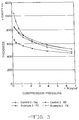
- the resiliency of prior art, binderless glass fiber separator is illustrated by compression curves presented in the Fig. 1.
- the compression characteristics, i.e., the thickness at various pressures, of this and other glass fiber separators were measured generally in accordance with the Battery Council International, (BCI) on apparatus including a block with an upper, hard, flat square surface approximately 15,24 cm by 15,24 cm.
- BCI Battery Council International
- a small round pressure foot with a lower, flat surface was mounted on a moveable fixture over the block and, so far as possible, the lower surface of the pressure foot was maintained parallel to the hard, flat block surface.
- the fixture included a dial micrometer for measuring the distance between the upper block surface and the lower pressure foot surface, as well as means for measuring the pressure, if any, exerted on the lower pressure plate surface.
- the thickness of the sample at that pressure was 0,19 cm, as measured by the dial micrometer. Additional measurements were made of the thickness of the sample at higher pressures and the data points are plotted in the graph which is Fig. 1. As the sample is subjected to successively higher pressures, its thickness is successively reduced. For a given sample, this test procedure can be repeated with virtually the same results. In other words, a sample that has been compressed under pressure of 421,8 or 492,1 g/cm 2 and its thickness reduced by approximately 35 percent will, upon release of the pressure, expand to its original thickness or very close to it. This elasticity of glass fiber separator material will by destroyed if it is subjected to pressure which is high enough to cause substantial glass fiber breakage.
- the threshold amount of pressure which will destroy elasticity for a given separator is affected by the diameter of fibers in the separator, the thickness of the separator and other factors, as well. In many cases, the elasticity will be destroyed by the amount of pressure required to reduce the thickness of a separator sample by about fifty percent.
- Glass fiber separator was produced from a blend of glass fibers comprising 35 percent w/w Manville 206 glass fibers, average fiber diameter of 0.75 ⁇ and 65 percent w/w Manville 210X glass fibers, average fiber diameter of 3.0 ⁇ .
- the separator had a grammage of 240 g/m 2 .
- acidified water specifically, deionized water to which H 2 SO 4 was added to achieve a pH of between 2.5 and 2.7, was added to the separator in an amount such that the ratio of the combined weight of the dry separator and the weight of the acidified water to the weight of the dry separator was 2.7:1.
- Example 1-PC the PC here means precompressed.
- Control 1-Dry a compression curve for a conventional, dry glass fiber separator corresponding in composition and grammage with the glass fiber separator of Example 1-PC.
- the Example 1-PC separator has a thickness which is between about 33% and 40% less, under various pressures, than the thickness of the Control 1-Dry separator at those pressures.
- a wetted separator in accordance with the invention, has suppressed resiliency by comparison with a dry but otherwise comparable separator.
- the significance of the resiliency suppression is greatly enhanced, however, by the fact that the resiliency can be restored in a controlled fashion.
- Example 1-PC separator sample was loaded into the Example 1-PC separator sample in an amount such that the ratio of the combined weights of the dry separator, the acidified water and the electrolyte to the weight of the dry separator was 7:1. This ratio was selected to approximate the amount of the total electrolyte in a VRLA battery that would be carried in the glass fiber separator. Thereafter, the compression characteristics of the Example 1-PC separator loaded with electrolyte, was measured and the resulting compression curve is presented in Fig. 2 in a plot labeled Example 1-7X.
- Example 1-7X the resiliency of the Example 1-PC separator was restored by loading it with electrolyte, as shown in the Example 1-7X plot.
- the resiliency of the Example 1-7X separator was substantially the same as the resiliency of the Control 1-Dry separator after it was loaded with electrolyte, specifically, H 2 SO 4 having a specific gravity of 1.286g, in an amount such that the ratio of the combined weight of the dry separator and the weight of the electrolyte to the weight of the dry separator was 7:1.
- This compression curve for the Control 1-Dry separator after it was loaded with electrolyte is presented in a plot designated Control 1-7X in Fig. 2.
- wetted separator with suppressed resiliency in accordance with the invention, when loaded with electrolyte in an amount similar to the amount it would carry in service, has restored resiliency substantially equal to that of conventional separator loaded with a like amount of electrolyte. Further tests were conducted on glass fiber separators of varying grammages.
- Glass fiber separator was produced from a blend of glass fibers comprising 35 percent w/w Manville 206 glass fibers, average fiber diameter of 0.75 ⁇ , and 65 percent w/w Manville 210X glass fibers, average fiber diameter of 3.0 ⁇ .
- the separator had a grammage of 280 g/m 2 .
- acidified water produced by adding H 2 SO 4 to deionized water in an amount such that the acid had a pH between 2.5 and 2.7, was added to the separator in an amount such that the ratio of the combined weight of the dry separator and the weight of the acidified water to the weight of the dry separator was 2.7:1.
- the wetted separator in accordance with the invention, was passed between compression rollers which were set so that, upon leaving the compression rollers, the wetted separator exhibited suppressed resiliency.
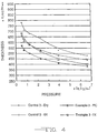
- a compression curve for this separator is presented in Fig. 3, designated Example 2-PC.
- Example 2-PC In order to illustrate the degree of resiliency suppression exhibited by Example 2-PC, there is a compression curve, designated Control 2-Dry in Fig. 3, for a conventional, dry glass fiber separator corresponding in composition and grammage with the glass fiber separator of Example 2-PC.
- the Example 2-PC separator has a thickness which is between about 6% and 37% less, under various pressures, than the thickness of the Control 2-Dry separator at those pressures.
- the Example 2-PC glass fiber has a thickness which is between about 20% and 37% less than the thickness of the Control 2-Dry separator.
- the Example 2-PC separator has suppressed resiliency by comparison with a dry but otherwise comparable separator and its resiliency can be restored in a controlled fashion.
- Example 2-PC separator sample was added to the Example 2-PC separator sample in an amount such that the ratio of the combined weight of the dry separator, the acidified water and the weight of the electrolyte to the weight of the dry separator was 7:1. This ratio was selected to approximate the amount of the total electrolyte in a VRLA battery that would be carried in the glass fiber separator. Thereafter, the compression characteristics of the Example 2-PC separator loaded with electrolyte, were measured and the results are presented in Fig. 3 in a plot labeled Example 2-7X.
- Example 2-7X the resiliency of the Example 2-PC separator was restored by the addition of electrolyte, as shown in the Example 2-7X plot.
- the resiliency of the Example 2-7X separator was substantially the same as the resiliency of the Control 2-Dry separator after it was loaded with electrolyte, specifically, H 2 SO 4 having a specific gravity of 1.286g, in an amount such that the ratio of the combined weight of the dry separator and the weight of the electrolyte to the weight of the dry separator was 7:1.
- the compression curve for this separator is designated Control 2-7X in Fig. 3.
- Glass fiber separator was produced from a blend of glass fibers comprising 35 percent w/w Manville 206 glass fibers, average fiber diameter of 0.75 ⁇ , and 65 percent w/w Manville 210X glass fibers, average fiber diameter of 3.0 ⁇ .
- the separator had a grammage of 260 g/m 2 .
- acidified water produced by adding H 2 SO 4 to deionized water in an amount such that the acidified water had a pH between 2.5 and 2.7, was added to the separator in an amount such that the ratio of the combined weight of the dry separator and the weight of the acidified water to the weight of the dry separator was 2.7:1.
- the wetted separator in accordance with the invention, was passed between compression rollers which were set so that, upon leaving the compression rollers, the wetted separator exhibited suppressed resiliency.
- a compression curve for this separator is presented in Fig. 4, designated Example 3-PC.
- Example 3-PC In order to illustrate the degree of resiliency suppression exhibited by Example 3-PC, there is a compression curve, designated Control 3-Dry in Fig. 4, for a conventional, dry glass fiber separator corresponding in composition and grammage with the glass fiber separator of Example 3-PC.
- the Example 3-PC separator has a thickness which is between about 20% and 30% less, under various pressures, than the thickness of the Control 3-Dry separator at those pressures.
- the Example 3-PC glass fiber has a thickness which is between about 23% and 30% less than the thickness of the Control 3-Dry separator.
- the Example 3-PC separator has suppressed resiliency by comparison with a dry but otherwise comparable separator and its resiliency can be restored in a controlled fashion.
- Example 3-PC separator sample was added to the Example 3-PC separator sample in an amount such that the ratio of the combined weight of the dry separator, acidified water and the weight of the electrolyte to the weight of the dry separator was 7:1. This ratio was selected to approximate the amount of the total electrolyte in a VRLA battery that would be carried in the glass fiber separator. Thereafter, the compression characteristics of the Example 3-PC separator loaded with electrolyte, were measured and the results are presented in Fig. 4 in a plot labeled Example 3-7X.
- Example 3-7X the resiliency of the Example 3-PC separator was restored by the addition of electrolyte, as shown in the Example 3-7X plot.
- the resiliency of the Example 3-7X separator was substantially the same as the resiliency of the Control 3-Dry separator after it was loaded with electrolyte, specifically, H 2 SO 4 having a specific gravity of 1.286g, in an amount such that the ratio of the combined weight of the dry separator and the weight of the electrolyte to the weight of the dry separator was 7:1.
- the compression curve for this separator is designated Control 3-7X in Fig. 4.
- Glass fiber separator was produced from a blend of glass fibers comprising 35 percent w/w Manville 206 glass fibers, average fiber diameter of 0.75 ⁇ , and 65 percent w/w Manville 210X glass fibers, average fiber diameter of 3.0 ⁇ .
- the separator had a grammage of 280 g/m 2 .
- acidified water produced by adding H 2 SO 4 to deionized water in an amount such that the acidified water had a pH between 2.5 and 2.7, was added to the separator in an amount such that the ratio of the combined weight of the dry separator and the weight of the acidified water to the weight of the dry separator was 2.7:1.
- Example 4-PC A compression curve for this separator is presented in Fig. 5, designated Example 4-PC.
- Control 4-Dry a compression curve, designated Control 4-Dry in Fig. 5, for a conventional, dry glass fiber separator corresponding in composition and grammage with the glass fiber separator of Example 4-PC.
- the Example 4-PC separator has a thickness which is between about 32% and 43% less, under various pressures, than the thickness of the Control 4-Dry separator at those pressures.
- the Example 4-PC separator has suppressed resiliency by comparison with a dry but otherwise comparable separator and its resiliency can be restored in a controlled fashion.
- Example 4-PC separator sample was added to the Example 4-PC separator sample in an amount such that the ratio of the combined weights of the dry separator, acidified water and the electrolyte to the weight of the dry separator was 7:1. This ratio was selected to approximate the amount of the total electrolyte in a VRLA battery that would be carried in the glass fiber separator. Thereafter, the compression characteristics of the Example 4-PC separator loaded with electrolyte, were measured and the results are presented in Fig. 5 in a plot labeled Example 4-7X.
- Example 4-7X the resiliency of the Example 4-PC separator was restored by the addition of electrolyte, as shown in the Example 4-7X plot.
- the resiliency of the Example 4-7X separator was substantially the same as the resiliency of the Control 4-Dry separator after it was loaded with electrolyte, specifically, H 2 SO 4 having a specific gravity of 1.286g, in an amount such that the ratio of the combined weight of the dry separator and the weight of the electrolyte to the weight of the dry separator was 7:1.
- the compression curve for this separator is designated Control 4-7X in Fig. 5.
- Glass fiber separator was produced from a blend of glass fibers comprising 35 percent w/w Manville 206 glass fibers, average fiber diameter of 0.75 ⁇ , and 65 percent w/w Manville 210X glass fibers, average fiber diameter of 3.0 ⁇ .
- the separator had a grammage of 300 g/m 2 .
- acidified water produced by adding H 2 SO 4 to deionized water in an amount such that the acid had a pH between 2.5 and 2.7, was added to the separator in an amount such that the ratio of the combined weight of the dry separator and the weight of the acidified water to the weight of the dry separator was 2.7:1.
- Example 5-PC A compression curve for this separator is presented in Fig. 6, designated Example 5-PC.
- Control 5-Dry a compression curve, designated Control 5-Dry in Fig. 6, for a conventional, dry glass fiber separator corresponding in composition and grammage with the glass fiber separator of Example 5-PC.
- the Example 5-PC separator has a thickness which is between about 38% and 42% less, under various pressures, than the thickness of the Control 5-Dry separator at those pressures.
- the Example 5-PC separator has suppressed resiliency by comparison with a dry but otherwise comparable separator and its resiliency can be restored in a controlled fashion.
- Example 5-PC separator sample was added to the Example 5-PC separator sample in an amount such that the ratio of the combined weights of the dry separator, the acidified water and the electrolyte to the weight of the dry separator was 7:1. This ratio was selected to approximate the amount of the total electrolyte in a VRLA battery that would be carried in the glass fiber separator. Thereafter, the compression characteristics of the Example 5-PC separator loaded with electrolyte, were measured and the results are presented in Fig. 6 in a plot labeled Example 5-7X.
- Example 5-PC separator was restored by the addition of electrolyte, as shown in the Example 5-7X plot.
- the resiliency of the Example 5-7X separator was substantially the same as the resiliency of the Control 5-Dry separator after it was loaded with electrolyte, specifically, H 2 SO 4 having a specific gravity of 1.286g, in an amount such that the ratio of the combined weight of the dry separator and the weight of the electrolyte to the weight of the dry separator was 7:1.
- the compression curve for this separator is designated Control 5-7X in Fig. 6.
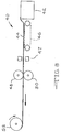
- apparatus for producing a VRLA battery cell is indicated generally at 10 and comprises glass fiber separator 12 supplied from a roll 14, liquid spray means 16 including a nozzle 18, upper and lower compression rollers 20 and 22, and a cutter 24.
- glass fiber separator 12 is unwound from the supply roll 14 and advances, right to left in Fig. 7, so that it passes under the spray nozzle 18 from which a controlled amount of resiliency suppressing liquid is sprayed or otherwise deposited on the glass fiber separator 12 as it passes below.
- the resiliency suppressing liquid is acidified water, specifically, deionized water to which sulfuric acid has been added to reach a pH of approximately 2.5 to 2.7.
- Other liquids known to be suitable for use in suppressing the resiliency of glass fiber separator include plain tap water, deionized water and sulfuric acid having a specific gravity of 1.286.
- the liquid will serve well as a vehicle for introducing additives into a battery, such as sodium sulfate to control dendrite growth as well as other chemicals for the same or other purposes.
- the amount of liquid sprayed or deposited on the glass fiber separator is preferably such that the ratio of the combined weight of the dry separator and the weight of the resiliency suppressing liquid to the weight of the dry separator is between 2:1 and 4:1; more preferably between 2.5:1 and 3:1 and, most preferably, about 2.7:1.
- the glass fiber separator 12 containing the resiliency suppressing liquid is advanced, right to left in Fig. 7, to pass between the compression rollers 20 and 22, which are set to compress the glass fiber separator to the extent that, upon leaving the compression rollers, the thickness of a separator according to the present invention, under a given nominal pressure, is reduced at least ten percent as compared with the thickness of dry glass fiber separator 12 under the same nominal pressure.
- the thickness of a separator according to the present invention is reduced by at least twenty percent, and, most preferably, the thickness is reduced by at least thirty percent.
- the reduced thickness separator is cut into separator sheets 26 having a length suitable for use in a given cell.
- the separator sheets are assembled with alternating positive electrodes 28 and negative electrodes 30 into a cell stack 32.
- the positive electrodes 28 and the negative electrodes 30 may either be tank formed, i.e., the paste material may be converted into active material outside the battery case or the electrodes may be formed in-situ after the cell stack is inserted into a battery case 34. In either case, the cell stack is assembled and inserted into the battery case 34. Because the separator sheets 26 have a reduced thickness, little or no compression need be applied to the cell stack in order to insert the cell stack within the case.
- polymeric sheets (not shown) may be positioned on the outside of the cell stack to facilitate insertion of the cell stack into the battery case 34.
- a head box 42 contains a glass fiber slurry which is deposited in a thin web 44 on a drainage screen 46.
- Drying devices 47 are provided in the apparatus and may comprises drying cans, heat lamps, drying ovens and other means for reducing the moisture content of the web 44.
- the moisture content of the web 44 would be preliminarily reduced on the drainage screen 46, and the moisture content of the web 44 would be further reduced, to virtually zero, by the drying devices 47.
- the glass fiber web is not dried completely; substantial moisture remains in the web 44 as it leaves the drying devices 47 and the moisture is present in a controlled amount.
- the amount of liquid which remains in the web is preferably such that, for a given piece of the web, the ratio of the combined weight of the web and the weight of the moisture to the weight the web would have if it was completely dried is between 2:1 and 4:1. More preferably, the ratio is between 2.5:1 and 3:1 and, most preferably, about 2.7:1.
- the web 44 Upon leaving the drainage screen 46, the web 44 is passed between upper and lower compression rollers 48 and 50, which are set to compress the web to the extent that, upon leaving the compression rollers 48 and 50, the thickness of the compressed web, under a given nominal pressure, is reduced at least ten percent as compared with the thickness that the web would have, under the same nominal pressure, if it was dried completely and had not been subjected to the action of the compression rollers 48 and 50.
- the thickness of a separator according to the present invention is reduced by at least ten percent, and, most preferably, reduced by at least thirty percent.
- the upper limit on thickness reduction is something which varies from separator to separator and is determined, in any ease, by the degree of compression which can be sustained by a given glass fiber separator without glass fiber breakage to the extent that the separator loses its integrity. Once the glass fiber web has been compressed, it can be wound up on a roll 52 for shipment to a battery manufacturing facility.
- Glass fiber separator was produced from a blend of glass fibers comprising 35 percent w/w Manville 206 glass fibers, average fiber diameter of 0.75 ⁇ , and 65 percent w/w Manville 210X glass fibers, average fiber diameter of 3.0 ⁇ .
- the separator had a grammage of 280 g/m 2 and a fiber surface area of 1.1m 2 /g.
- sulfuric acid having a specific gravity of 1.286 was added to the separator in an amount such that the ratio of the combined weight of the dry separator and the weight of the acid to the weight of the dry separator was 2.7:1.
- the wetted separator in accordance with the invention, was passed between compression rollers which were set so that, upon leaving the compression rollers, the wetted separator exhibited suppressed resiliency.
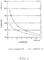
- a compression curve for this separator is presented in Fig. 9, designated Example 6-PC.
- the degree of resiliency suppression exhibited by Example 6-PC is illustrated in Fig. 10 where the compression curve for Example 6-PC is plotted along with a compression curve, designated Control 6-Dry, for a conventional, dry glass fiber separator corresponding in composition and grammage with the glass fiber separator of Example 3-PC.
- the Example 6-PC separator has a thickness which is between about 20% and 34% less, under various pressures, than the thickness of the Control 7-Dry separator at those pressures.
- the Example 6-PC glass fiber Under nominal pressures of 281,2 g/cm 2 and less, the Example 6-PC glass fiber has a thickness which is between about 24% and 34% less than the thickness of the Control 7-Dry separator.
- the Example 6-PC separator has suppressed resiliency by comparison with a dry but otherwise comparable separator and its resiliency can be restored in a controlled fashion.
- Example 6-PC separator sample was added to the Example 6-PC separator sample in an amount such that the ratio of the combined weights of the dry separator and of the electrolyte to the weight of the dry separator was 7:1. This ratio was selected to approximate the amount of the total electrolyte in a VRLA battery that would be carried in the glass fiber separator.
- the compression characteristics of the Example 6-PC separator loaded with electrolyte were measured and the results are presented in Fig. 9 in a plot labeled Example 6-7X. To a large extent, the resiliency of the Example 6-PC separator was restored by the addition of electrolyte, as shown in the Example 6-7X plot.
- the resiliency of the Example 6-7X separator is compared to the resiliency Control 7-Dry separator after it was loaded with electrolyte, specifically, H 2 SO 4 having a specific gravity of 1.286g, in an amount such that the ratio of the combined weight of the dry separator and the weight of the electrolyte to the weight of the dry separator was 7:1.
- electrolyte specifically, H 2 SO 4 having a specific gravity of 1.286g
Landscapes
- Chemical & Material Sciences (AREA)
- Engineering & Computer Science (AREA)
- Chemical Kinetics & Catalysis (AREA)
- Electrochemistry (AREA)
- General Chemical & Material Sciences (AREA)
- Manufacturing & Machinery (AREA)
- Ceramic Engineering (AREA)
- Inorganic Chemistry (AREA)
- Cell Separators (AREA)
- Secondary Cells (AREA)
Abstract
Description
- The invention relates to a method for producing a valve regulated lead acid battery comprising a battery case and at least one cell made up of a separator comprising glass fibers, such a separator and a method for producing such a separator.
- The battery comprises at least one positive plate, at least one negative plate and an amount of electrolyte contained in the plates and separator wherein a first portion of said amount of electrolyte is absorbed in and held by the separator.
- Valve regulated ("sealed") lead acid (VRLA) batteries are known and they can comprise a plurality of positive and negative plates, as in a prismatic cell, or layers of separator and electrode tightly wound together, as in a "jelly roll" cell. The plates are arranged so that they alternate, negative - positive - negative, etc., with separator material separating each plate from adjacent plates. The separator, typically composed of a mat of glass fibers, serves many purposes. A primary purpose of the separator is to electrically insulate one plate from the other. In addition, in VRLA batteries, glass fiber separator material provides innumerable gas channels between the plates through which oxygen can migrate from the positive electrode when generated there to the negative electrode where it can be recombined with hydrogen, according to the oxygen cycle.
- Glass fiber separator material is produced commercially on paper making equipment. In most cases, no binder is used to make separator sheets; the entanglement of individual fibers serve to maintain the sheet in a cohesive structure. A great deal of work has been directed to modifying the glass fiber furnish to improve battery performance. Some of the work has entailed the addition of synthetic fibers for various reasons.
- Separators for valve regulated batteries comprising glass fiber sheet material are disclosed in all the following patents: US-A-4,465,748, US-A-4,216,280, US-A-4,367,271, JP 55/146,872, US-A-4,245,013 and US-A-4,908,282.
- It is recognized that, in order to obtain good performance in VRLA batteries, the cell stack comprising the plates and separators must be maintained under compression so that good contact is maintained between the separators and the plates. If the cell stack components reach a condition where they are not under substantial compression, battery failure will occur. In flat plate cells, this compression is conventionally achieved by assembling the cell stack components into a cell stack having a given thickness, physically compressing the cell stack, and inserting the compressed cell stack in a battery case which is sized, relative to the size of the cell stack, to mantain the components of the cell stack under compression. The step of compressing the cell stack is a difficult one because substantial compression is needed. After a cell stack is inserted into a battery case, electrolyte is added. However, because of the compression within a cell stack in a battery case, the rate at which electrolyte is absorbed into the pores of the plates and the separator is very slow. Typically, it takes several minutes to fill a VRLA battery case with electrolyte, even when a vacuum is drawn in the case.
- Recently, some effort has been directed to the production of separators which are pre-compressed. EP-A-334091 discloses a dry glass fiber separator which is pre-compressed and is maintained in that state by means of a water or acid soluble binder, preferably methyl cellulose. According to this patent document, the binder can be mixed in with the glass fiber slurry before it reaches the drying screen of a paper making machine. After most of the liquid in the slurry has been removed from the web, it is compressed between compression rollers. The web leaves the compression rollers at a reduced thickness and the binder adheres the glass fibers together in a compressed state which is maintained by the binder throughout the final drying of the web. The patent document alternatively discloses the application of a water soluble binder to the glass fibers after they have been formed into a web, followed by the steps of compressing and drying.
- US-A-5,091,275 (Brecht et al.) discloses a glass fiber separator which expands when exposed to electrolyte. The separator comprises glass fibers which are impregnated with an aqueous solution of colloidal silica particles and a sulfate salt. The separator is produced by forming a paper making web of glass fibers, impregnating the web with the aqueous mixture of silica and a salt, lightly compressing the impregnated web to remove some of the aqueous solution, partially drying the web, compressing the web to a final thickness and completing the drying of the web. The web is preferably compressed to a thicknesess which is less than the distance between plates in a given cell, so that insertion of an assembled cell stack into a case is facilitated. When electrolyte is added to the case, the salt dissolves in the electrolyte and the separator expands to provide good contact between the plates and the separators. According to the patent, the silica contributes to the recombination performance of cells incorporating the precompressed separator. The silica also contributes a great deal of stiffness to the separator, so much so that the separator may be characterized as rigid.
- International patent application WO 81/01076 discloses a method for assembling a VRLA battery wherein dry separator and plates are assembled into a cell stack, pressure is applied to the cell stack to compress it, electrolyte is added to the compressed cell stack and the pressure is removed but, according to the application, the cell stack maintains its compressed thickness, thereby making it easier to insert the cell stack in the battery case. The amount of electrolyte added is preferably the final amount of electrolyte which will be in the battery.
- It should be noted that, in a conventional process for producing glass fiber separator, a glass fiber web is typically passed between compression rollers in the vicinity of the drying screen, in order to produce glass fiber separator of a desired caliper or thickness. This results in an insubstantial thickness reduction of the web at a time when it still contains a large amount of moisture from the glass fiber slurry from which the web is produced. It is believed that the moisture content of the web when it is compressed in accordance with this conventional technique for controlling its thickness, is such that the ratio of the combined weight of the dry separator and the weight of the moisture to the weight of the dry separator would be between 8:1 and 10:1.
- It is an object of the present invention to provide glass fiber separator with inhibited resiliency and reduced thickness.
- It is a further object of the present invention to use such separator in the production of VRLA batteries where the addition of the final electrolyte restores the resiliency of the glass mat so that there is good compression within the cell stack.
- It is yet another object of the invention to provide an improved method for producing VRLA batteries using a separator according to the present invention wherein the filling of a battery case with electrolyte is greatly facilitated.
- According to the invention the method for producing a valve regulated lead acid battery comprises the steps of:
- producing a substantially binder-free glass fiber separator having a first thickness when dry and containing an amount of plain tap or deionized water, sulfuric acid or mixtures of them as a resiliency suppressing liquid which amount is substantially less than the first portion of said amount of electrolyte and the liquid being substantially free of a binder for the glass fiber separator,
- compressing the separator to the extent that, when the compression is released, the separator has a second thickness which is substantially less than said first thickness,
- positioning the reduced thickness separator containing said amount of liquid between the positive and negative plates to produce a cell,
- easing the cell into the battery case wherein the cell components are under a degree of pressure, and
- adding electrolyte to the cell whereby the pressure between the components of the cell is increased by the restoration of the resiliency of the separator as electrolyte is absorbed in it.
-
- The method for producing treated glass fiber separator comprises the following steps:
- producing a substantially binder-free web of glass fibers from a substantially binder-free slurry comprising glass fibers and an amount of plain tap or deionized water, sulfuric acid or mixtures of them as a resiliency suppressing liquid,
- removing some of the liquid from the web until there remains such an amount of liquid in said web that the ratio of the combined weight of the liquid and the separator to the weight of the dry separator is between 2:1 and 4:1,
- compressing the web containing said amount of liquid, and
releasing the compression to produce a glass fiber separator
having a first thickness,
wherein, the first thickness of the compressed web is substantially less than the thickness of the web would be if it had been dried and not compressed, and wherein said amount of liquid is operable to maintain the thickness of the web at the first thickness. -
- A sheet useful as a separator in a valve regulated lead acid battery comprises
- glass fibers formed into a substantially binder-free resilient web having a first thickness when dry, and an amount of plain tap or deionized water, sulfuric acid or mixtures of them as a resiliency suppressing liquid carried in said web, said amount beeing substantially less than said amount of electrolyte and said liquid beeing substantially free of a binder for the fibers of the web, wherein said web has been wet with said substantially lesser amount of said liquid, and has been compressed and wherein the amount of liquid carried in said web is such that it is operable, when the compression is released, to suppress the reliancy of the web to maintain said web at a second thicknes which is at least ten percent less than said first thickness, but wherein the resiliency of the separator is restored as electrolyte is added to it.
-
- Further details can be taken out of the depending claims.
- Unless the context indicates otherwise, references in the specification and the claims to comparative thickness of separators should be understood to mean the thickness of such separators under nominal, substantially identical, pressures because, as is known to those skilled in the art, one cannot obtain a meaningful thickness measurement of glass fiber separator materials under no pressure; only when some pressure is applied does a thickness measurement have some repeatability and reliability. As used herein and in the appended claims, the phrase "substantially binder free" is to be understood to refer to glass fiber webs or sheets in which the primary mechanism for holding the sheet or web together is the entanglement of individual glass fibers as opposed to an adhesive binder mechanism such as that obtained by the addition of methyl cellulose to glass fibers. The phrase "substantially binder free" is not meant to exclude glass fiber webs or sheets which include materials which contribute to some minor degree of ionic bonding, for example, glass fiber webs or sheets which contain sodium sulfate which suppresses dendritic growth but which also contributes to minor ionic binding of the fibers; fibers in such a sheet or web would still be bound together primarily by fiber entanglement and the web or sheet itself would be substantially binder free. Similarly, references to a resiliency suppressing liquid which is "substantially free of a binder" is meant to refer to liquids which do not contain adhesive binders or binders which, if added to a glass fiber sheet or web, would replace the entanglement of individual fibers as the primary binder mechanism in the web. That phrase is not meant to exclude liquids which contain, for example, sodium sulfate or other materials which would contribute a minor degree of ionic bonding.
- The invention is based upon the discovery that binder-free glass fiber separators of a given thickness can be wetted with a controlled amount of liquid and compressed to a substantially reduced thickness and, further, that the moisture will suppress the natural resiliency of the glass fiber separator so that it will have a substantially reduced thickness when the compression is released, even when the glass fiber separator is unrestrained. The amount of liquid required to suppress the resiliency of the glass mat seperator is substantially less than the minimum amount of the portion of electrolyte which would be carried in the separator in a finished cell. The amount of liquid required to suppress the resiliency of the glass mat separator is also substantially less than the amount of electrolyte added to the cell stack components, outside of the battery case, according to the teachings of International patent application WO 81/01076, and less than the moisture content of a web when it is compressed in accordance with the convention technique for controlling its thickness. Moreover, in order to produce separator with inhibited resiliency and reduced thickness in accordance wih the present invention, it must contain substantially less moisture, when it is compressed, than the wet web when it is compressed to control thickness, and less moisture than the separator in the cell stack when it is compressed in accordance with the disclosure of International patent application WO 81/01076.
- The invention is based upon the further discovery that when sufficient electrolyte is added to the moistened, reduced thickness separator, its resiliency is substantially restored and it will expand work or, if confined within a cell stack within a case, it will try to expand, thereby placing the confined cell stack components under compression. The invention is also based upon the discovery that moistened, reduced thickness separator can be used to enormous advantage in a method for producing batteries because the reduced thickness of the separator reduces or eliminates the need to compress a cell stack in order to place it within a battery case. Moreover, when electrolyte is added to the cell, the resiliency of the glass mat separator is restored and the components of the cell stack expand against the constraints of the battery case, thereby achieving a level of compression required for good performance.
- The use of moistened, reduced thickness separator in a battery according to the invention greatly facilitates the filling of the battery cell with electrolyte and promotes a good, even distribution of electrolyte, thereby reducing the incidence of dry bands of separator.
-
- Fig. 1 is a compression curve showing the compression characteristics, i.e., thickness, at various pressures, of prior art glass fiber separator materials, one in a dry state and several wetted with various amounts of sulfuric acid having a specific gravity of 1.286.
- Fig. 2 is a compression curve and a rebound curve showing the compression characteristics, before and after electrolyte loading, of two glass fiber separator materials, one produced in accordance with the present invention, and one corresponding with prior art separator material.
- Fig. 3 is a compression curve and a rebound curve showing the compression characteristics, before and after electrolyte loading, of two glass fiber separator materials, one produced in accordance with the present invention, and one corresponding with prior art separator material.
- Fig. 4 is a compression curve and a rebound curve showing the compression characteristics, before and after electrolyte loading, of two glass fiber separator materials, one produced in accordance with the present invention, and one corresponding with prior art separator material.
- Fig. 5 is a compression curve and a rebound curve showing the compression characteristics, before and after electrolyte loading, of two glass fiber separator materials, one produced in accordance with the present invention, and one corresponding with prior art separator material.
- Fig. 6 is a compression curve and a rebound curve showing the compression characteristics, before and after electrolyte loading, of two glass fiber separator materials, one produced in accordance with the present invention, and one corresponding with prior art separator material.
- Fig. 7 is a schematic diagram of a station in a battery line where glass fiber separator material is wetted, compressed to a reduced thickness, cut to size, assembled in a cell stack which is then inserted, easily, into a battery case, according to the method of the present invention.
- Fig. 8 is a schematic diagram of paper making equipment including apparatus for producing separator with inhibited resiliency in accordance with the method of the present invention.
- Fig. 9 is a compression curve and a rebound curve showing the compression characteristics, before and after electrolyte loading, of a glass fiber separator material produced in accordance with the present invention.
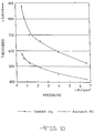
- Fig. 10 is a compression curve showing the compression characteristics, before and after electrolyte loading, of a glass fiber separator material corresponding with prior art separator material.
- Fig. 11 is a compression curve showing the compression characteristics, after electrolyte loading, of two glass fiber separator materials, one produced in accordance with the present invention, and one corresponding with prior art separator material.
- Fig. 12 is a compression curve showing the compression characteristics, before and after electrolyte loading, of a glass fiber separator material corresponding with prior art separator material.
-
- The present invention is a binder-free glass fiber separator with temporarily inhibited resiliency and reduced thickness. Dry, binderless glass fiber separator useful in VRLA batteries is resilient under certain conditions. When compressed under relatively mild pressure applied to its major surfaces, the thickness of glass fiber separator is reduced. When the compression pressure is released, the separator rebounds and returns to its original thickness, or something very close. Of course, if too much pressure is applied to the major surfaces of dry, binderless glass fiber separator, there will be severe fiber breakage and resiliency will be lost.
- The resiliency of prior art, binderless glass fiber separator is illustrated by compression curves presented in the Fig. 1. The compression characteristics, i.e., the thickness at various pressures, of this and other glass fiber separators were measured generally in accordance with the Battery Council International, (BCI) on apparatus including a block with an upper, hard, flat square surface approximately 15,24 cm by 15,24 cm.
- A small round pressure foot with a lower, flat surface was mounted on a moveable fixture over the block and, so far as possible, the lower surface of the pressure foot was maintained parallel to the hard, flat block surface. The fixture included a dial micrometer for measuring the distance between the upper block surface and the lower pressure foot surface, as well as means for measuring the pressure, if any, exerted on the lower pressure plate surface.
- The apparatus and procedure described above were used to measure the thickness and resiliency of conventional, prior art glass fiber separator which was produced from a blend of glass fibers comprising 35 percent w/w (percent by weight) Manville 206 glass fibers, average fiber diameter of 0.75µ and 65 percent w/w Manville 210X glass fibers, average fiber diameter of 3.0µ. The separator had a grammage of 260 g/m2. A piece of the dry separator material (Prior Art-Dry) was cut into a square sample, about 7,6 to 10 cm square. The lower major surface of the sample was placed on the block and the pressure plate was lowered until a nominal pressure of approximately 42,18 g/cm2 was observed. The thickness of the sample at that pressure was 0,19 cm, as measured by the dial micrometer. Additional measurements were made of the thickness of the sample at higher pressures and the data points are plotted in the graph which is Fig. 1. As the sample is subjected to successively higher pressures, its thickness is successively reduced. For a given sample, this test procedure can be repeated with virtually the same results. In other words, a sample that has been compressed under pressure of 421,8 or 492,1 g/cm2 and its thickness reduced by approximately 35 percent will, upon release of the pressure, expand to its original thickness or very close to it. This elasticity of glass fiber separator material will by destroyed if it is subjected to pressure which is high enough to cause substantial glass fiber breakage. The threshold amount of pressure which will destroy elasticity for a given separator is affected by the diameter of fibers in the separator, the thickness of the separator and other factors, as well. In many cases, the elasticity will be destroyed by the amount of pressure required to reduce the thickness of a separator sample by about fifty percent.
- Additional measurements were taken to investigate the compression characteristics of glass fiber separator corresponding with the Prior Art-Dry except that, prior to testing, the samples were loaded with electrolyte, specifically, H2SO4 having a specific gravity of 1.286g. Electrolyte was added to one sample, designated Prior Art-6X in Fig. 1, in a controlled amount so that the ratio of the combined weight of the dry separator and the weight of the electrolyte to the weight of the dry separator was 6:1. Additional samples were tested in which this ratio was 7:1, 8:1, 9:1 and 10:1 and they are identified in Fig. 1 by the legends Prior Art-7X, Prior Art-8X, Prior Art-9X and Prior Art-10X, respectively. The samples which were loaded with electrolyte behaved elastically and their thickness curves in Fig. 1 are extremely similar to the compression curve for Prior Art-Dry.
- Glass fiber separator was produced from a blend of glass fibers comprising 35 percent w/w Manville 206 glass fibers, average fiber diameter of 0.75µ and 65 percent w/w Manville 210X glass fibers, average fiber diameter of 3.0µ. The separator had a grammage of 240 g/m2. In accordance with the present invention, acidified water, specifically, deionized water to which H2SO4 was added to achieve a pH of between 2.5 and 2.7, was added to the separator in an amount such that the ratio of the combined weight of the dry separator and the weight of the acidified water to the weight of the dry separator was 2.7:1. The wetted separator, in accordance with the invention, was passed between compression rollers which were set so that, upon leaving the compression rollers, the wetted separator exhibited suppressed resiliency, as explained below. A compression curve for this glass fiber separator is presented in Fig. 2, designated Example 1-PC (the PC here means precompressed). In order to illustrate the degree of resiliency suppression exhibited by Example 1-PC, there is a compression curve, designated Control 1-Dry in Fig. 2 for a conventional, dry glass fiber separator corresponding in composition and grammage with the glass fiber separator of Example 1-PC. The Example 1-PC separator has a thickness which is between about 33% and 40% less, under various pressures, than the thickness of the Control 1-Dry separator at those pressures. Thus, it is shown that a wetted separator, in accordance with the invention, has suppressed resiliency by comparison with a dry but otherwise comparable separator. The significance of the resiliency suppression is greatly enhanced, however, by the fact that the resiliency can be restored in a controlled fashion.
- After the testing described above, electrolyte, specifically, H2SO4 having a specific gravity of 1.286g, was loaded into the Example 1-PC separator sample in an amount such that the ratio of the combined weights of the dry separator, the acidified water and the electrolyte to the weight of the dry separator was 7:1. This ratio was selected to approximate the amount of the total electrolyte in a VRLA battery that would be carried in the glass fiber separator. Thereafter, the compression characteristics of the Example 1-PC separator loaded with electrolyte, was measured and the resulting compression curve is presented in Fig. 2 in a plot labeled Example 1-7X. To a large extent, the resiliency of the Example 1-PC separator was restored by loading it with electrolyte, as shown in the Example 1-7X plot. In fact, the resiliency of the Example 1-7X separator was substantially the same as the resiliency of the Control 1-Dry separator after it was loaded with electrolyte, specifically, H2SO4 having a specific gravity of 1.286g, in an amount such that the ratio of the combined weight of the dry separator and the weight of the electrolyte to the weight of the dry separator was 7:1. This compression curve for the Control 1-Dry separator after it was loaded with electrolyte is presented in a plot designated Control 1-7X in Fig. 2. Accordingly, it is demonstrated that wetted separator with suppressed resiliency, in accordance with the invention, when loaded with electrolyte in an amount similar to the amount it would carry in service, has restored resiliency substantially equal to that of conventional separator loaded with a like amount of electrolyte. Further tests were conducted on glass fiber separators of varying grammages.
- Glass fiber separator was produced from a blend of glass fibers comprising 35 percent w/w Manville 206 glass fibers, average fiber diameter of 0.75µ, and 65 percent w/w Manville 210X glass fibers, average fiber diameter of 3.0µ. The separator had a grammage of 280 g/m2. In accordance with the present invention, acidified water produced by adding H2SO4 to deionized water in an amount such that the acid had a pH between 2.5 and 2.7, was added to the separator in an amount such that the ratio of the combined weight of the dry separator and the weight of the acidified water to the weight of the dry separator was 2.7:1. The wetted separator, in accordance with the invention, was passed between compression rollers which were set so that, upon leaving the compression rollers, the wetted separator exhibited suppressed resiliency. A compression curve for this separator is presented in Fig. 3, designated Example 2-PC. In order to illustrate the degree of resiliency suppression exhibited by Example 2-PC, there is a compression curve, designated Control 2-Dry in Fig. 3, for a conventional, dry glass fiber separator corresponding in composition and grammage with the glass fiber separator of Example 2-PC. The Example 2-PC separator has a thickness which is between about 6% and 37% less, under various pressures, than the thickness of the Control 2-Dry separator at those pressures. Under nominal pressures of 140,6 g/cm2 and less, the Example 2-PC glass fiber has a thickness which is between about 20% and 37% less than the thickness of the Control 2-Dry separator. Like the separator of Example 1, the Example 2-PC separator has suppressed resiliency by comparison with a dry but otherwise comparable separator and its resiliency can be restored in a controlled fashion.
- After the testing described above, electrolyte, specifically, H2SO4 having a specific gravity of 1.286g, was added to the Example 2-PC separator sample in an amount such that the ratio of the combined weight of the dry separator, the acidified water and the weight of the electrolyte to the weight of the dry separator was 7:1. This ratio was selected to approximate the amount of the total electrolyte in a VRLA battery that would be carried in the glass fiber separator. Thereafter, the compression characteristics of the Example 2-PC separator loaded with electrolyte, were measured and the results are presented in Fig. 3 in a plot labeled Example 2-7X. To a large extent, the resiliency of the Example 2-PC separator was restored by the addition of electrolyte, as shown in the Example 2-7X plot. In fact, the resiliency of the Example 2-7X separator was substantially the same as the resiliency of the Control 2-Dry separator after it was loaded with electrolyte, specifically, H2SO4 having a specific gravity of 1.286g, in an amount such that the ratio of the combined weight of the dry separator and the weight of the electrolyte to the weight of the dry separator was 7:1. The compression curve for this separator is designated Control 2-7X in Fig. 3.
- Glass fiber separator was produced from a blend of glass fibers comprising 35 percent w/w Manville 206 glass fibers, average fiber diameter of 0.75µ, and 65 percent w/w Manville 210X glass fibers, average fiber diameter of 3.0µ .The separator had a grammage of 260 g/m2. In accordance with the present invention, acidified water produced by adding H2SO4 to deionized water in an amount such that the acidified water had a pH between 2.5 and 2.7, was added to the separator in an amount such that the ratio of the combined weight of the dry separator and the weight of the acidified water to the weight of the dry separator was 2.7:1. The wetted separator, in accordance with the invention, was passed between compression rollers which were set so that, upon leaving the compression rollers, the wetted separator exhibited suppressed resiliency. A compression curve for this separator is presented in Fig. 4, designated Example 3-PC. In order to illustrate the degree of resiliency suppression exhibited by Example 3-PC, there is a compression curve, designated Control 3-Dry in Fig. 4, for a conventional, dry glass fiber separator corresponding in composition and grammage with the glass fiber separator of Example 3-PC. The Example 3-PC separator has a thickness which is between about 20% and 30% less, under various pressures, than the thickness of the Control 3-Dry separator at those pressures. Under nominal pressures of 281,2 g/cm2 and less, the Example 3-PC glass fiber has a thickness which is between about 23% and 30% less than the thickness of the Control 3-Dry separator. Like the separator of Examples 1 and 2, the Example 3-PC separator has suppressed resiliency by comparison with a dry but otherwise comparable separator and its resiliency can be restored in a controlled fashion.
- After the testing described above, additional electrolyte, specifically, H2SO4 having a specific gravity of 1.286g, was added to the Example 3-PC separator sample in an amount such that the ratio of the combined weight of the dry separator, acidified water and the weight of the electrolyte to the weight of the dry separator was 7:1. This ratio was selected to approximate the amount of the total electrolyte in a VRLA battery that would be carried in the glass fiber separator. Thereafter, the compression characteristics of the Example 3-PC separator loaded with electrolyte, were measured and the results are presented in Fig. 4 in a plot labeled Example 3-7X. To a large extent, the resiliency of the Example 3-PC separator was restored by the addition of electrolyte, as shown in the Example 3-7X plot. In fact, the resiliency of the Example 3-7X separator was substantially the same as the resiliency of the Control 3-Dry separator after it was loaded with electrolyte, specifically, H2SO4 having a specific gravity of 1.286g, in an amount such that the ratio of the combined weight of the dry separator and the weight of the electrolyte to the weight of the dry separator was 7:1. The compression curve for this separator is designated Control 3-7X in Fig. 4.
- Glass fiber separator was produced from a blend of glass fibers comprising 35 percent w/w Manville 206 glass fibers, average fiber diameter of 0.75µ, and 65 percent w/w Manville 210X glass fibers, average fiber diameter of 3.0µ. The separator had a grammage of 280 g/m2. In accordance with the present invention, acidified water produced by adding H2SO4 to deionized water in an amount such that the acidified water had a pH between 2.5 and 2.7, was added to the separator in an amount such that the ratio of the combined weight of the dry separator and the weight of the acidified water to the weight of the dry separator was 2.7:1. The wetted separator, in accordance with the invention, was passed between compression rollers which were set so that, upon leaving the compression rollers, the wetted separator exhibited suppressed resiliency. A compression curve for this separator is presented in Fig. 5, designated Example 4-PC. In order to illustrate the degree of resiliency suppression exhibited by Example 4-PC, there is a compression curve, designated Control 4-Dry in Fig. 5, for a conventional, dry glass fiber separator corresponding in composition and grammage with the glass fiber separator of Example 4-PC. The Example 4-PC separator has a thickness which is between about 32% and 43% less, under various pressures, than the thickness of the Control 4-Dry separator at those pressures. Like the separators of Examples 1, 2 and 3, the Example 4-PC separator has suppressed resiliency by comparison with a dry but otherwise comparable separator and its resiliency can be restored in a controlled fashion.
- After the testing described above, additional electrolyte, specifically, H2SO4 having a specific gravity of 1.286g, was added to the Example 4-PC separator sample in an amount such that the ratio of the combined weights of the dry separator, acidified water and the electrolyte to the weight of the dry separator was 7:1. This ratio was selected to approximate the amount of the total electrolyte in a VRLA battery that would be carried in the glass fiber separator. Thereafter, the compression characteristics of the Example 4-PC separator loaded with electrolyte, were measured and the results are presented in Fig. 5 in a plot labeled Example 4-7X. To a large extent, the resiliency of the Example 4-PC separator was restored by the addition of electrolyte, as shown in the Example 4-7X plot. In fact, the resiliency of the Example 4-7X separator was substantially the same as the resiliency of the Control 4-Dry separator after it was loaded with electrolyte, specifically, H2SO4 having a specific gravity of 1.286g, in an amount such that the ratio of the combined weight of the dry separator and the weight of the electrolyte to the weight of the dry separator was 7:1. The compression curve for this separator is designated Control 4-7X in Fig. 5.
- Glass fiber separator was produced from a blend of glass fibers comprising 35 percent w/w Manville 206 glass fibers, average fiber diameter of 0.75µ, and 65 percent w/w Manville 210X glass fibers, average fiber diameter of 3.0µ. The separator had a grammage of 300 g/m2. In accordance with the present invention, acidified water produced by adding H2SO4 to deionized water in an amount such that the acid had a pH between 2.5 and 2.7, was added to the separator in an amount such that the ratio of the combined weight of the dry separator and the weight of the acidified water to the weight of the dry separator was 2.7:1. The wetted separator, in accordance with the invention, was passed between compression rollers which were set so that, upon leaving the compression rollers, the wetted separator exhibited suppressed resiliency. A compression curve for this separator is presented in Fig. 6, designated Example 5-PC. In order to illustrate the degree of resiliency suppression exhibited by Example 5-PC, there is a compression curve, designated Control 5-Dry in Fig. 6, for a conventional, dry glass fiber separator corresponding in composition and grammage with the glass fiber separator of Example 5-PC. The Example 5-PC separator has a thickness which is between about 38% and 42% less, under various pressures, than the thickness of the Control 5-Dry separator at those pressures. Like the separators of Examples 1-4, the Example 5-PC separator has suppressed resiliency by comparison with a dry but otherwise comparable separator and its resiliency can be restored in a controlled fashion.
- After the testing described above, additional electrolyte, specifically, H2SO4 having a specific gravity of 1.286g, was added to the Example 5-PC separator sample in an amount such that the ratio of the combined weights of the dry separator, the acidified water and the electrolyte to the weight of the dry separator was 7:1. This ratio was selected to approximate the amount of the total electrolyte in a VRLA battery that would be carried in the glass fiber separator. Thereafter, the compression characteristics of the Example 5-PC separator loaded with electrolyte, were measured and the results are presented in Fig. 6 in a plot labeled Example 5-7X. To a large extent, the resiliency of the Example 5-PC separator was restored by the addition of electrolyte, as shown in the Example 5-7X plot. In fact, the resiliency of the Example 5-7X separator was substantially the same as the resiliency of the Control 5-Dry separator after it was loaded with electrolyte, specifically, H2SO4 having a specific gravity of 1.286g, in an amount such that the ratio of the combined weight of the dry separator and the weight of the electrolyte to the weight of the dry separator was 7:1. The compression curve for this separator is designated Control 5-7X in Fig. 6.
- Referring now to Fig. 7, apparatus for producing a VRLA battery cell is indicated generally at 10 and comprises
glass fiber separator 12 supplied from aroll 14, liquid spray means 16 including anozzle 18, upper andlower compression rollers cutter 24. - According to the method of the present invention,
glass fiber separator 12 is unwound from thesupply roll 14 and advances, right to left in Fig. 7, so that it passes under thespray nozzle 18 from which a controlled amount of resiliency suppressing liquid is sprayed or otherwise deposited on theglass fiber separator 12 as it passes below. According to the preferred embodiment of this method, the resiliency suppressing liquid is acidified water, specifically, deionized water to which sulfuric acid has been added to reach a pH of approximately 2.5 to 2.7. Other liquids known to be suitable for use in suppressing the resiliency of glass fiber separator include plain tap water, deionized water and sulfuric acid having a specific gravity of 1.286. It is contemplated that the liquid will serve well as a vehicle for introducing additives into a battery, such as sodium sulfate to control dendrite growth as well as other chemicals for the same or other purposes. The amount of liquid sprayed or deposited on the glass fiber separator is preferably such that the ratio of the combined weight of the dry separator and the weight of the resiliency suppressing liquid to the weight of the dry separator is between 2:1 and 4:1; more preferably between 2.5:1 and 3:1 and, most preferably, about 2.7:1. - The
glass fiber separator 12 containing the resiliency suppressing liquid is advanced, right to left in Fig. 7, to pass between thecompression rollers glass fiber separator 12 under the same nominal pressure. Preferably, the thickness of a separator according to the present invention is reduced by at least twenty percent, and, most preferably, the thickness is reduced by at least thirty percent. It will be appreciated that, because of the resiliency of theglass fiber separator 12, in order to produce a separator with a thickness reduced by thirty percent, it will be necessary to set thecompression rollers separator 12 is between them, its thickness is reduced by more than thirty percent and, upon leaving the compression roller, the thickness of the separator will increase, somewhat, from the thickness it had when it was exactly between therollers - After leaving the
compression rollers separator sheets 26 having a length suitable for use in a given cell. The separator sheets are assembled with alternatingpositive electrodes 28 andnegative electrodes 30 into acell stack 32. Thepositive electrodes 28 and thenegative electrodes 30 may either be tank formed, i.e., the paste material may be converted into active material outside the battery case or the electrodes may be formed in-situ after the cell stack is inserted into abattery case 34. In either case, the cell stack is assembled and inserted into thebattery case 34. Because theseparator sheets 26 have a reduced thickness, little or no compression need be applied to the cell stack in order to insert the cell stack within the case. In accordance with known practice, polymeric sheets (not shown) may be positioned on the outside of the cell stack to facilitate insertion of the cell stack into thebattery case 34. - Owing to the reduced thickness of the
separator sheets 26 in thecell stack 32, there is a very low degree of compression in the components of the cell stack. When electrolyte is loaded into the battery case, however, the resiliency of theindividual separator sheets 26 is restored and substantial degree of compression of the cell stack components is achieved. When thecell stack 32 within thebattery case 34 is loaded with electrolyte, theseparator sheets 26 will try to expand but, because thebattery case 34 constrains the cell stack components against expansion, compression is built up within thecell stack 32. - Referring now to Fig. 8, apparatus for producing reduced thickness separator according to the present invention is indicated generally at 40. A
head box 42 contains a glass fiber slurry which is deposited in athin web 44 on adrainage screen 46.Drying devices 47 are provided in the apparatus and may comprises drying cans, heat lamps, drying ovens and other means for reducing the moisture content of theweb 44. In conventional paper making, the moisture content of theweb 44 would be preliminarily reduced on thedrainage screen 46, and the moisture content of theweb 44 would be further reduced, to virtually zero, by the dryingdevices 47. In contrast, and in accordance with the present invention, the glass fiber web is not dried completely; substantial moisture remains in theweb 44 as it leaves the dryingdevices 47 and the moisture is present in a controlled amount. The amount of liquid which remains in the web is preferably such that, for a given piece of the web, the ratio of the combined weight of the web and the weight of the moisture to the weight the web would have if it was completely dried is between 2:1 and 4:1. More preferably, the ratio is between 2.5:1 and 3:1 and, most preferably, about 2.7:1. - Upon leaving the
drainage screen 46, theweb 44 is passed between upper andlower compression rollers compression rollers compression rollers roll 52 for shipment to a battery manufacturing facility. - Glass fiber separator was produced from a blend of glass fibers comprising 35 percent w/w Manville 206 glass fibers, average fiber diameter of 0.75µ, and 65 percent w/w Manville 210X glass fibers, average fiber diameter of 3.0µ. The separator had a grammage of 280 g/m2 and a fiber surface area of 1.1m2/g. In accordance with the present invention, sulfuric acid having a specific gravity of 1.286 was added to the separator in an amount such that the ratio of the combined weight of the dry separator and the weight of the acid to the weight of the dry separator was 2.7:1. The wetted separator, in accordance with the invention, was passed between compression rollers which were set so that, upon leaving the compression rollers, the wetted separator exhibited suppressed resiliency. A compression curve for this separator is presented in Fig. 9, designated Example 6-PC. The degree of resiliency suppression exhibited by Example 6-PC is illustrated in Fig. 10 where the compression curve for Example 6-PC is plotted along with a compression curve, designated Control 6-Dry, for a conventional, dry glass fiber separator corresponding in composition and grammage with the glass fiber separator of Example 3-PC. The Example 6-PC separator has a thickness which is between about 20% and 34% less, under various pressures, than the thickness of the Control 7-Dry separator at those pressures. Under nominal pressures of 281,2 g/cm2 and less, the Example 6-PC glass fiber has a thickness which is between about 24% and 34% less than the thickness of the Control 7-Dry separator. The Example 6-PC separator has suppressed resiliency by comparison with a dry but otherwise comparable separator and its resiliency can be restored in a controlled fashion.
- After the testing described above, electrolyte, specifically, H2SO4 having a specific gravity of 1.286g, was added to the Example 6-PC separator sample in an amount such that the ratio of the combined weights of the dry separator and of the electrolyte to the weight of the dry separator was 7:1. This ratio was selected to approximate the amount of the total electrolyte in a VRLA battery that would be carried in the glass fiber separator. Thereafter, the compression characteristics of the Example 6-PC separator loaded with electrolyte, were measured and the results are presented in Fig. 9 in a plot labeled Example 6-7X. To a large extent, the resiliency of the Example 6-PC separator was restored by the addition of electrolyte, as shown in the Example 6-7X plot.
- In Fig. 11, the resiliency of the Example 6-7X separator is compared to the resiliency Control 7-Dry separator after it was loaded with electrolyte, specifically, H2SO4 having a specific gravity of 1.286g, in an amount such that the ratio of the combined weight of the dry separator and the weight of the electrolyte to the weight of the dry separator was 7:1. The compression curve for control separator loaded with electrolyte is designated Control 7-7X in Fig. 11.
- In Fig. 12, the compression curve for the Control 7-Dry separator and the compression curve for the Control 7-7X separator are plotted together. The loading of the convention Control 7-Dry separator with electrolyte has virtually no effect on the compression characteristics of this material.
Claims (6)
- A method for producing a valve regulated lead acid battery comprising a battery case and at least one cell made up of a separator comprising glass fibers, at least one positive plate, at least one negative plate and an amount of electrolyte contained in the plates and separator wherein a first portion of said amount of electrolyte is absorbed in and held by the separator, said method comprising the steps of:producing a substantially binder-free glass fiber separator having a first thickness when dry and containing an amount of plain tap or deionized water, sulfuric acid or mixtures of them as a resiliency suppressing liquid which amount is substantially less than the first portion of said amount of electrolyte and the liquid being substantially free of a binder for the glass fiber separator,compressing the separator to the extent that, when the compression is released, the separator has a second thickness which is substantially less than said first thickness,positioning the reduced thickness separator containing said amount of liquid between the positive and negative plates to produce a cell,easing the cell into the battery case wherein the cell components are tinder a degree of pressure, andadding electrolyte to the cell whereby the pressure between the components of the cell is increased by the restoration of the resiliency of the separator as electrolyte is absorbed in it.
- The method claimed in claim 1 wherein the ratio of the combined weight of said amount of liquid and the separator to the weight of the dry separator is between 2:1 and 4:1.
- A method for producing treated glass fiber separator with suppressed, restorable resiliency, said treated glass fiber separator having a reduced thickness by comparison with untreated glass fiber separator, said method comprising the steps ofproducing a substantially binder-free web of glass fibers from a substantially binder-free slurry comprising glass fibers and an amount of plain tap or deionized water, sulfuric acid or mixtures of them as a resiliency suppressing liquid,removing some of the liquid from the web until there remains such an amount of liquid in said web that the ratio of the combined weight of the liquid and the separator to the weight of the dry separator is between 2:1 and 4:1,compressing the web containing said amount of liquid, and releasing the compression to produce a glass fiber separator having a first thickness,
wherein, the first thickness of the compressed web is substantially less than the thickness of the web would be if it had been dried and not compressed, and wherein said amount of liquid is operable to maintain the thickness of the web at the first thickness. - The method claimed in one of the foregoing claims wherein said second thickness is at least twenty percent less than said first thickness.
- The method claimed in one of the foregoing claims wherein the ratio of the combined weight of said amount of liquid and the separator to the weight of the dry separator is between 2.5:1 and 3:1.
- A sheet useful as a separator in a valve regulated lead acid battery wherein an amount of electrolyte is absorbed in the separator, said sheet comprising glass fibers formed into a substantially binder-free resilient web having a first thickness when dry, and an amount of plain tap or deionized water, sulfuric acid or mixtures of them as a resiliency suppressing liquid carried in said web, said amount beeing substantially less than said amount of electrolyte and said liquid beeing substantially free of a binder for the fibers of the web, wherein said web has been wet with said substantially lesser amount of said liquid, and has been compressed and wherein the amount of liquid carried in said web is such that it is operable, when the compression is released, to suppress the reliancy of the web to maintain said web at a second thicknes which is at least ten percent less than said first thickness, but wherein the resiliency of the separator is restored as electrolyte is added to it.
Applications Claiming Priority (3)
| Application Number | Priority Date | Filing Date | Title |
|---|---|---|---|
| US07/881,160 US5336275A (en) | 1992-05-11 | 1992-05-11 | Method for assembling battery cells containing pre-compressed glass fiber separators |
| US881160 | 1992-05-11 | ||
| PCT/US1993/004386 WO1993023885A1 (en) | 1992-05-11 | 1993-05-11 | Pre-compressed glass fiber separators for batteries and method for assembling battery cells |
Publications (3)
| Publication Number | Publication Date |
|---|---|
| EP0672304A1 EP0672304A1 (en) | 1995-09-20 |
| EP0672304A4 EP0672304A4 (en) | 1995-11-22 |
| EP0672304B1 true EP0672304B1 (en) | 2000-01-26 |
Family
ID=25377890
Family Applications (1)
| Application Number | Title | Priority Date | Filing Date |
|---|---|---|---|
| EP93911187A Expired - Lifetime EP0672304B1 (en) | 1992-05-11 | 1993-05-11 | Pre-compressed glass fiber separators for batteries and method for assembling battery cells |
Country Status (6)
| Country | Link |
|---|---|
| US (2) | US5336275A (en) |
| EP (1) | EP0672304B1 (en) |
| JP (1) | JPH07508126A (en) |
| AU (1) | AU4241293A (en) |
| DE (1) | DE69327727T2 (en) |
| WO (1) | WO1993023885A1 (en) |
Families Citing this family (36)
| Publication number | Priority date | Publication date | Assignee | Title |
|---|---|---|---|---|
| US5512065A (en) * | 1993-10-12 | 1996-04-30 | Gnb Battery Technologies Inc. | Methods for assembling lead-acid batteries |
| US5618642A (en) * | 1995-06-06 | 1997-04-08 | Daramic, Inc. | Battery separator with sodium sulfate |
| CZ292941B6 (en) * | 1995-09-20 | 2004-01-14 | Hollingsworth And Vose Company (Mass.Corp) | Multi-layer sheet useful as a separator and process for producing thereof |
| DE19627614A1 (en) * | 1996-07-09 | 1998-01-15 | Hoppecke Zoellner Sohn Accu | Process for the production of release materials |
| AU4593697A (en) * | 1996-09-20 | 1998-04-14 | Johns Manville International, Inc. | Resilient mat; a method of making the resilient mat and a battery including the resilient mat |
| EP0949705B1 (en) * | 1998-04-10 | 2006-11-22 | Johns Manville International Inc. | Battery with encapsulated electrode plates |
| US6641951B1 (en) | 1998-09-21 | 2003-11-04 | Douglas Battery Manufacturing Company | Battery cell tray assembly and sytem |
| US6162559A (en) * | 1998-09-21 | 2000-12-19 | Douglas Battery Manufacturing Company | Compressed battery system for motive power applications |
| US6153335A (en) * | 1998-09-25 | 2000-11-28 | Douglas Battery Manufacturing Company | Battery cell construction including fiberous mat separator |
| US6194100B1 (en) | 1998-09-28 | 2001-02-27 | Douglas Battery Manufacturing Co. | Method for making valve-regulated lead acid battery with vacuum draw down |
| US6406813B2 (en) * | 1999-04-02 | 2002-06-18 | Gnb Technologies, Inc. | Lead-acid separators and cells and batteries using such separators |
| US6410181B1 (en) | 1999-05-05 | 2002-06-25 | Wilson Greatbatch Ltd. | High temperature lithium oxyhalide electrochemical cell |
| JP2003524281A (en) * | 1999-10-06 | 2003-08-12 | スクワナクック テクノロジーズ エルエルシー | Battery paste |
| US6531248B1 (en) | 1999-10-06 | 2003-03-11 | Squannacook Technologies Llc | Battery paste |
| US7097939B2 (en) | 2001-07-13 | 2006-08-29 | Hollingsworth & Vose Company | Gel-forming battery separator |
| US6780540B2 (en) | 2001-08-08 | 2004-08-24 | Delphi Technologies, Inc. | Element sleeve for a battery |
| US7159805B2 (en) | 2002-03-25 | 2007-01-09 | Evanite Fiber Corporation | Methods of modifying fibers |
| US6929858B2 (en) * | 2002-03-25 | 2005-08-16 | Squannacook Technologies Llc | Glass fibers |
| US8592329B2 (en) | 2003-10-07 | 2013-11-26 | Hollingsworth & Vose Company | Vibrationally compressed glass fiber and/or other material fiber mats and methods for making the same |
| US12172111B2 (en) | 2004-11-05 | 2024-12-24 | Donaldson Company, Inc. | Filter medium and breather filter structure |
| US8057567B2 (en) | 2004-11-05 | 2011-11-15 | Donaldson Company, Inc. | Filter medium and breather filter structure |
| EP1827649B1 (en) | 2004-11-05 | 2013-02-27 | Donaldson Company, Inc. | Filter medium and structure |
| US8021457B2 (en) | 2004-11-05 | 2011-09-20 | Donaldson Company, Inc. | Filter media and structure |
| US8177875B2 (en) | 2005-02-04 | 2012-05-15 | Donaldson Company, Inc. | Aerosol separator; and method |
| WO2006091594A1 (en) | 2005-02-22 | 2006-08-31 | Donaldson Company, Inc. | Aerosol separator |
| EP2117674A1 (en) | 2007-02-22 | 2009-11-18 | Donaldson Company, Inc. | Filter element and method |
| WO2008103821A2 (en) | 2007-02-23 | 2008-08-28 | Donaldson Company, Inc. | Formed filter element |
| US8267681B2 (en) | 2009-01-28 | 2012-09-18 | Donaldson Company, Inc. | Method and apparatus for forming a fibrous media |
| US20120102725A1 (en) * | 2010-10-28 | 2012-05-03 | Gm Global Technology Operations, Inc. | Battery Separator |
| US12590393B2 (en) | 2011-09-30 | 2026-03-31 | Owens Corning Intellectual Capital, Llc | Method of forming a web from fibrous materials |
| AU2012315361A1 (en) | 2011-09-30 | 2014-04-17 | Owens Corning Intellectual Capital, Llc | Method of forming a web from fibrous materails |
| US10177360B2 (en) | 2014-11-21 | 2019-01-08 | Hollingsworth & Vose Company | Battery separators with controlled pore structure |
| DE102017007858A1 (en) | 2017-04-03 | 2018-10-04 | Thorsten Gerdes | Method for direct application of glass-based separators to battery electrodes |
| DE102017205653A1 (en) | 2017-04-03 | 2018-10-04 | Vitrulan Textile Glass Gmbh | Glass-based battery separator |
| CN108847472A (en) * | 2018-05-07 | 2018-11-20 | 浙江天能动力能源有限公司 | A kind of method of determining lead-acid accumulator acid adding amount |
| CN117219959A (en) * | 2023-10-09 | 2023-12-12 | 重庆再升科技股份有限公司 | AGM separator and preparation method and application thereof |
Family Cites Families (16)
| Publication number | Priority date | Publication date | Assignee | Title |
|---|---|---|---|---|
| US3553020A (en) * | 1968-12-20 | 1971-01-05 | Gen Motors Corp | Spill-proof battery |
| JPS5445755A (en) * | 1977-09-19 | 1979-04-11 | Yuasa Battery Co Ltd | Separator for storage battery |
| US4245013A (en) * | 1978-05-11 | 1981-01-13 | Chloride Group Limited | Battery separators |
| JPS55146872A (en) * | 1979-05-01 | 1980-11-15 | Hitachi Maxell Ltd | Organic electrolyte battery |
| US4373015A (en) * | 1979-05-09 | 1983-02-08 | Chloride Group Limited | Electric storage batteries |
| WO1981001076A1 (en) * | 1979-10-08 | 1981-04-16 | Chloride Group Ltd | Electric storage batteries |
| JPS5699968A (en) * | 1980-01-12 | 1981-08-11 | Nippon Muki Kk | Separator for battery |
| US4359511A (en) * | 1980-06-30 | 1982-11-16 | Texon Inc. | Battery separator material |
| US4363856A (en) * | 1980-06-30 | 1982-12-14 | Texon Inc. | Battery separator material |
| US4391036A (en) * | 1981-07-31 | 1983-07-05 | Yuasa Battery Company Limited | Process for producing sealed lead-acid battery |
| US4529677A (en) * | 1982-02-02 | 1985-07-16 | Texon Incorporated | Battery separator material |
| ZA832713B (en) * | 1982-04-20 | 1984-08-29 | Evans Adlard & Co | Glass fibre paper separator for electrochemical cells |
| US4648177A (en) * | 1983-10-21 | 1987-03-10 | Gates Energy Products, Inc. | Method for producing a sealed lead-acid cell |
| US4908282A (en) * | 1986-11-12 | 1990-03-13 | Hollingsworth And Vose Company | Recombinant battery and plate separator therefor |
| DE3810125A1 (en) * | 1988-03-25 | 1989-10-12 | Varta Batterie | SEPARATOR MADE OF FIBERGLASS |
| US5091275A (en) * | 1990-04-25 | 1992-02-25 | Evanite Fiber Corporation | Glass fiber separator and method of making |
-
1992
- 1992-05-11 US US07/881,160 patent/US5336275A/en not_active Expired - Fee Related
-
1993
- 1993-05-11 JP JP6503670A patent/JPH07508126A/en active Pending
- 1993-05-11 AU AU42412/93A patent/AU4241293A/en not_active Abandoned
- 1993-05-11 WO PCT/US1993/004386 patent/WO1993023885A1/en not_active Ceased
- 1993-05-11 DE DE69327727T patent/DE69327727T2/en not_active Expired - Fee Related
- 1993-05-11 EP EP93911187A patent/EP0672304B1/en not_active Expired - Lifetime
-
1994
- 1994-08-08 US US08/287,081 patent/US5468572A/en not_active Expired - Fee Related
Also Published As
| Publication number | Publication date |
|---|---|
| WO1993023885A1 (en) | 1993-11-25 |
| EP0672304A4 (en) | 1995-11-22 |
| EP0672304A1 (en) | 1995-09-20 |
| US5336275A (en) | 1994-08-09 |
| AU4241293A (en) | 1993-12-13 |
| JPH07508126A (en) | 1995-09-07 |
| US5468572A (en) | 1995-11-21 |
| DE69327727T2 (en) | 2000-10-05 |
| DE69327727D1 (en) | 2000-03-02 |
Similar Documents
| Publication | Publication Date | Title |
|---|---|---|
| EP0672304B1 (en) | Pre-compressed glass fiber separators for batteries and method for assembling battery cells | |
| US4606982A (en) | Sealed lead-acid cell and method | |
| CA1242760A (en) | Method for producing a sealed lead-acid cell | |
| EP0526563B1 (en) | Glass fiber separator and method of making | |
| US6495286B2 (en) | Glass fiber separators for lead-acid batteries | |
| EP3281241B1 (en) | Battery separators comprising inorganic particles | |
| US4637966A (en) | Sealed lead-acid cell | |
| US4965147A (en) | Separator for an electrochemical cell of the metal-air type and having an alkaline electrolyte | |
| US4429442A (en) | Method of producing a lead-acid battery utilizing vibrational energy | |
| CA2260005C (en) | Glass fiber separators for batteries | |
| EP0129627B1 (en) | Method of loading porous fibrous plaques | |
| EP0528473A2 (en) | Separator for mat-immobilized-electrolyte battery | |
| US6468687B1 (en) | Alkaline storage battery with reinforced separators | |
| EP1533861B1 (en) | High power lead-acid battery with enhanced cycle life | |
| US6319629B1 (en) | Glass-fibre reinforced absorbent separator | |
| WO1981001076A1 (en) | Electric storage batteries | |
| JPH0729560A (en) | Separator for sealed lead-acid battery | |
| JPH0422541Y2 (en) | ||
| US5348823A (en) | Process of preparing an electrode for an electrochemical cell with a porous support and an electrode obtained by said process | |
| EP0289596B1 (en) | Method of producing a sealed lead/sulfuric acid recombinant storage battery | |
| KR0138533B1 (en) | Recombination Battery and its Plate Separator | |
| WO2025106476A1 (en) | Battery separators with reduced pore sizes | |
| JP3448982B2 (en) | Manufacturing method of retainer for sealed lead-acid battery | |
| JPH11354093A (en) | Secondary battery separator | |
| GB2062944A (en) | Electric storage batteries |
Legal Events
| Date | Code | Title | Description |
|---|---|---|---|
| PUAI | Public reference made under article 153(3) epc to a published international application that has entered the european phase |
Free format text: ORIGINAL CODE: 0009012 |
|
| 17P | Request for examination filed |
Effective date: 19941205 |
|
| AK | Designated contracting states |
Kind code of ref document: A1 Designated state(s): DE FR GB IT |
|
| A4 | Supplementary search report drawn up and despatched |
Effective date: 19951006 |
|
| AK | Designated contracting states |
Kind code of ref document: A4 Designated state(s): DE FR GB IT |
|
| 17Q | First examination report despatched |
Effective date: 19960419 |
|
| GRAG | Despatch of communication of intention to grant |
Free format text: ORIGINAL CODE: EPIDOS AGRA |
|
| GRAG | Despatch of communication of intention to grant |
Free format text: ORIGINAL CODE: EPIDOS AGRA |
|
| GRAH | Despatch of communication of intention to grant a patent |
Free format text: ORIGINAL CODE: EPIDOS IGRA |
|
| GRAH | Despatch of communication of intention to grant a patent |
Free format text: ORIGINAL CODE: EPIDOS IGRA |
|
| GRAA | (expected) grant |
Free format text: ORIGINAL CODE: 0009210 |
|
| AK | Designated contracting states |
Kind code of ref document: B1 Designated state(s): DE FR GB IT |
|
| REF | Corresponds to: |
Ref document number: 69327727 Country of ref document: DE Date of ref document: 20000302 |
|
| ITF | It: translation for a ep patent filed | ||
| ET | Fr: translation filed | ||
| PLBE | No opposition filed within time limit |
Free format text: ORIGINAL CODE: 0009261 |
|
| STAA | Information on the status of an ep patent application or granted ep patent |
Free format text: STATUS: NO OPPOSITION FILED WITHIN TIME LIMIT |
|
| 26N | No opposition filed | ||
| REG | Reference to a national code |
Ref country code: GB Ref legal event code: IF02 |
|
| PGFP | Annual fee paid to national office [announced via postgrant information from national office to epo] |
Ref country code: GB Payment date: 20050427 Year of fee payment: 13 |
|
| PG25 | Lapsed in a contracting state [announced via postgrant information from national office to epo] |
Ref country code: IT Free format text: LAPSE BECAUSE OF NON-PAYMENT OF DUE FEES;WARNING: LAPSES OF ITALIAN PATENTS WITH EFFECTIVE DATE BEFORE 2007 MAY HAVE OCCURRED AT ANY TIME BEFORE 2007. THE CORRECT EFFECTIVE DATE MAY BE DIFFERENT FROM THE ONE RECORDED. Effective date: 20050511 |
|
| PGFP | Annual fee paid to national office [announced via postgrant information from national office to epo] |
Ref country code: FR Payment date: 20050519 Year of fee payment: 13 |
|
| PGFP | Annual fee paid to national office [announced via postgrant information from national office to epo] |
Ref country code: DE Payment date: 20050531 Year of fee payment: 13 |
|
| PG25 | Lapsed in a contracting state [announced via postgrant information from national office to epo] |
Ref country code: GB Free format text: LAPSE BECAUSE OF NON-PAYMENT OF DUE FEES Effective date: 20060511 |
|
| PG25 | Lapsed in a contracting state [announced via postgrant information from national office to epo] |
Ref country code: DE Free format text: LAPSE BECAUSE OF NON-PAYMENT OF DUE FEES Effective date: 20061201 |
|
| GBPC | Gb: european patent ceased through non-payment of renewal fee |
Effective date: 20060511 |
|
| REG | Reference to a national code |
Ref country code: FR Ref legal event code: ST Effective date: 20070131 |
|
| PG25 | Lapsed in a contracting state [announced via postgrant information from national office to epo] |
Ref country code: FR Free format text: LAPSE BECAUSE OF NON-PAYMENT OF DUE FEES Effective date: 20060531 |
|
| PGFP | Annual fee paid to national office [announced via postgrant information from national office to epo] |
Ref country code: IT Payment date: 20060531 Year of fee payment: 14 |
|
| PGRI | Patent reinstated in contracting state [announced from national office to epo] |
Ref country code: IT Effective date: 20080301 |
|
| PGRI | Patent reinstated in contracting state [announced from national office to epo] |
Ref country code: IT Effective date: 20080301 |