EP0672233B1 - Trans-critical vapour compression device - Google Patents
Trans-critical vapour compression device Download PDFInfo
- Publication number
- EP0672233B1 EP0672233B1 EP94903151A EP94903151A EP0672233B1 EP 0672233 B1 EP0672233 B1 EP 0672233B1 EP 94903151 A EP94903151 A EP 94903151A EP 94903151 A EP94903151 A EP 94903151A EP 0672233 B1 EP0672233 B1 EP 0672233B1
- Authority
- EP
- European Patent Office
- Prior art keywords
- circuit
- pressure
- refrigerant
- heat exchanger
- vapour compression
- Prior art date
- Legal status (The legal status is an assumption and is not a legal conclusion. Google has not performed a legal analysis and makes no representation as to the accuracy of the status listed.)
- Expired - Lifetime
Links
Images

Classifications
-
- F—MECHANICAL ENGINEERING; LIGHTING; HEATING; WEAPONS; BLASTING
- F25—REFRIGERATION OR COOLING; COMBINED HEATING AND REFRIGERATION SYSTEMS; HEAT PUMP SYSTEMS; MANUFACTURE OR STORAGE OF ICE; LIQUEFACTION SOLIDIFICATION OF GASES
- F25B—REFRIGERATION MACHINES, PLANTS OR SYSTEMS; COMBINED HEATING AND REFRIGERATION SYSTEMS; HEAT PUMP SYSTEMS
- F25B45/00—Arrangements for charging or discharging refrigerant
-
- F—MECHANICAL ENGINEERING; LIGHTING; HEATING; WEAPONS; BLASTING
- F25—REFRIGERATION OR COOLING; COMBINED HEATING AND REFRIGERATION SYSTEMS; HEAT PUMP SYSTEMS; MANUFACTURE OR STORAGE OF ICE; LIQUEFACTION SOLIDIFICATION OF GASES
- F25B—REFRIGERATION MACHINES, PLANTS OR SYSTEMS; COMBINED HEATING AND REFRIGERATION SYSTEMS; HEAT PUMP SYSTEMS
- F25B1/00—Compression machines, plants or systems with non-reversible cycle
-
- F—MECHANICAL ENGINEERING; LIGHTING; HEATING; WEAPONS; BLASTING
- F25—REFRIGERATION OR COOLING; COMBINED HEATING AND REFRIGERATION SYSTEMS; HEAT PUMP SYSTEMS; MANUFACTURE OR STORAGE OF ICE; LIQUEFACTION SOLIDIFICATION OF GASES
- F25B—REFRIGERATION MACHINES, PLANTS OR SYSTEMS; COMBINED HEATING AND REFRIGERATION SYSTEMS; HEAT PUMP SYSTEMS
- F25B9/00—Compression machines, plants or systems, in which the refrigerant is air or other gas of low boiling point
- F25B9/002—Compression machines, plants or systems, in which the refrigerant is air or other gas of low boiling point characterised by the refrigerant
- F25B9/008—Compression machines, plants or systems, in which the refrigerant is air or other gas of low boiling point characterised by the refrigerant the refrigerant being carbon dioxide
-
- F—MECHANICAL ENGINEERING; LIGHTING; HEATING; WEAPONS; BLASTING
- F25—REFRIGERATION OR COOLING; COMBINED HEATING AND REFRIGERATION SYSTEMS; HEAT PUMP SYSTEMS; MANUFACTURE OR STORAGE OF ICE; LIQUEFACTION SOLIDIFICATION OF GASES
- F25B—REFRIGERATION MACHINES, PLANTS OR SYSTEMS; COMBINED HEATING AND REFRIGERATION SYSTEMS; HEAT PUMP SYSTEMS
- F25B2309/00—Gas cycle refrigeration machines
- F25B2309/06—Compression machines, plants or systems characterised by the refrigerant being carbon dioxide
- F25B2309/061—Compression machines, plants or systems characterised by the refrigerant being carbon dioxide with cycle highest pressure above the supercritical pressure
-
- F—MECHANICAL ENGINEERING; LIGHTING; HEATING; WEAPONS; BLASTING
- F25—REFRIGERATION OR COOLING; COMBINED HEATING AND REFRIGERATION SYSTEMS; HEAT PUMP SYSTEMS; MANUFACTURE OR STORAGE OF ICE; LIQUEFACTION SOLIDIFICATION OF GASES
- F25B—REFRIGERATION MACHINES, PLANTS OR SYSTEMS; COMBINED HEATING AND REFRIGERATION SYSTEMS; HEAT PUMP SYSTEMS
- F25B2400/00—Component parts or details not otherwise provided for in this subclass
- F25B2400/16—Receivers
-
- F—MECHANICAL ENGINEERING; LIGHTING; HEATING; WEAPONS; BLASTING
- F25—REFRIGERATION OR COOLING; COMBINED HEATING AND REFRIGERATION SYSTEMS; HEAT PUMP SYSTEMS; MANUFACTURE OR STORAGE OF ICE; LIQUEFACTION SOLIDIFICATION OF GASES
- F25B—REFRIGERATION MACHINES, PLANTS OR SYSTEMS; COMBINED HEATING AND REFRIGERATION SYSTEMS; HEAT PUMP SYSTEMS
- F25B2600/00—Control issues
- F25B2600/17—Control issues by controlling the pressure of the condenser
Definitions
- the present invention relates to a vapour compression system operating at both subcritical and supercritical high-side pressures.
- the high-side pressure is determined by the condensing temperature, via the saturation pressure characteristics of the refrigerant.
- the high side pressure in such systems is always well below the critical pressure.
- vapour compression systems operating with supercritical high-side pressure, i.e. in a trans-critical cycle, the operating pressure depends on several factors such as momentary refrigerant charge in the high side, component volumes and temperature of heat rejection.
- a simple vapour compression system with expansion device of conventional design e.g. of the thermostatic type, would also be able to provide trans-critical cycle operation when the heat rejection temperature is above the critical temperature of the refrigerant.
- Such a system could give a simple and low-cost embodiment for a trans-critical vapour compression cycle using environmentally benign refrigerants such as CO 2 .
- This simple circuit does not include any mechanisms for high-side pressure modulation, and the pressure will therefore be determined by the operating conditions and the system design.
- a serious drawback in trans-critical operation of a system that is designed in accordance with common practice from conventional subcritical units is that, most likely, a relatively low refrigerating capacity and a poor efficiency will be obtained, due to far from optimum high side pressures during operation. This will result in a considerable reduction in capacity as supercritical conditions are established in the high side of the circuit.
- the loss in refrigerating capacity may be compensated for by increased compressor volume, but then at the cost of significantly higher power consumption and higher investments.
- WO-A-90/07683 shows a trans-critical vapour compression cycle device including a capacity regulation, said regulation being achieved by variation of the instant refrigerant charge in the high pressure side of the circuit.
- Still another disadvantage is that excessive pressures can easily build up in a fully charged non-operating system subjected to high ambient temperatures. The latter effect can cause damages, or can be taken into account in the design, but then at the cost of heavy, voluminous and expensive components and tubes.
- a conventional vapour compression circuit includes a compressor 1, a heat rejecting heat exchanger 2, an expansion device 3 and an evaporating heat exchanger 4 connected in series.
- a high-side pressure providing a maximum ratio between refrigerating capacity and compressor shaft power should be provided.
- a major parameter in the determination of the magnitude of this "optimum" pressure level is the refrigerant temperature at the outlet of the heat rejecting heat exchanger, i.e. the gas cooler.
- the most desirable relation between refrigerant temperature at the gas cooler outlet and the high side pressure, in order to maintain maximum energy efficiency of the circuit, can be calculated from thermodynamic data for the refrigerant or by practical measurements.
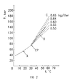
- Fig. 2 the conditions for CO 2 are shown in Fig. 2. Isochoric curves for 0.50 - 0.66 kg/l are indicated by dashed lines C, and the curve giving an optimum relation between gas cooler refrigerant outlet temperature and high-side pressure is shown in the diagramme as curve B, while the A curve depicts a saturation pressure curve for subcritical conditions.
- the isochor corresponding to a high-side charge of about 0.60 kg/l is quite close to the optimum-pressure curve. If the high side of the system is charged with 0.60 kg of CO 2 per liter internal volume, close to maximum efficiency will be maintained regardless of heat rejection temperature.
- the high-side of the circuit has an internal volume and an instant refrigerant charge that gives this desired density, changes in heat rejection temperature will result in high-side pressure changes corresponding quite accurately with the desired "optimum" curve.
- the volume of refrigerant should be relatively large at this location. In practice, this can be obtained by installing or connecting an extra volume, e.g. a receiver, into the circuit at or close to the gas cooler refrigerant outlet, or by providing a relatively large part of the total heat exchanger volume at or near the outlet.
- the low side of the circuit mainly comprises the evaporator, the low-pressure lines and the compressor crankcase.
- the high-side volume should be relatively large compared to the low-side volume, and a major fraction of the high-side volume should be located at or near the gas cooler outlet.
- a charge-to-volume ratio (density) ⁇ H in the high side giving the desired temperature-pressure relationship at varying temperature may be found, as indicated in Example 1 for CO 2 .
- V L ⁇ V H m L ⁇ m H m m H + m L
- V V H + V L m ⁇ m H V ⁇ V H ⁇ ⁇ ⁇ H
- m, V and ⁇ refers to the overall charge, volume and resulting average density for the entire circuit.
- a separate expansion vessel 5 can be connected to the low side via a valve 6, as shown in Fig. 3.
- the valve is opened when the pressure in the circuit exceeds a certain pre-set maximum limit in a manner known per se.
- valve 6 When the low-side pressure is reduced during start-up of the system, the valve 6 is opened and the necessary charge returned to the circuit, in order to re-establish the desired charge-to-volume ratio in the high side.
- the valve 6 is shut when the high-side pressure has reached the desired level in correspondence with the measured refrigerant temperature at the gas cooler outlet. Other parameters than the gas cooler refrigerant outlet temperature can also be applied in determining the valve shut-off pressure.
Landscapes
- Engineering & Computer Science (AREA)
- General Engineering & Computer Science (AREA)
- Physics & Mathematics (AREA)
- Mechanical Engineering (AREA)
- Thermal Sciences (AREA)
- Chemical Kinetics & Catalysis (AREA)
- Chemical & Material Sciences (AREA)
- Compression-Type Refrigeration Machines With Reversible Cycles (AREA)
- Air-Conditioning For Vehicles (AREA)
- Error Detection And Correction (AREA)
- Transition And Organic Metals Composition Catalysts For Addition Polymerization (AREA)
- Filling Or Discharging Of Gas Storage Vessels (AREA)
- Vaporization, Distillation, Condensation, Sublimation, And Cold Traps (AREA)
Abstract
Description
- The present invention relates to a vapour compression system operating at both subcritical and supercritical high-side pressures.
- In conventional vapour compression systems, the high-side pressure is determined by the condensing temperature, via the saturation pressure characteristics of the refrigerant. The high side pressure in such systems is always well below the critical pressure.
- In vapour compression systems operating with supercritical high-side pressure, i.e. in a trans-critical cycle, the operating pressure depends on several factors such as momentary refrigerant charge in the high side, component volumes and temperature of heat rejection.
- A simple vapour compression system with expansion device of conventional design, e.g. of the thermostatic type, would also be able to provide trans-critical cycle operation when the heat rejection temperature is above the critical temperature of the refrigerant. Such a system could give a simple and low-cost embodiment for a trans-critical vapour compression cycle using environmentally benign refrigerants such as CO2. This simple circuit does not include any mechanisms for high-side pressure modulation, and the pressure will therefore be determined by the operating conditions and the system design.
- A serious drawback in trans-critical operation of a system that is designed in accordance with common practice from conventional subcritical units is that, most likely, a relatively low refrigerating capacity and a poor efficiency will be obtained, due to far from optimum high side pressures during operation. This will result in a considerable reduction in capacity as supercritical conditions are established in the high side of the circuit. The loss in refrigerating capacity may be compensated for by increased compressor volume, but then at the cost of significantly higher power consumption and higher investments.
- Another major disadvantage in trans-critical operation of a conventionally designed system is that leakage of refrigerant will immediately affect the high side pressure, due to the reduction in high-side charge. At supercritical high side conditions, the pressure is determined by the relation between instant refrigerant charge and component volumes, similar to the conditions in a gas-charged pressure vessel.
- WO-A-90/07683 shows a trans-critical vapour compression cycle device including a capacity regulation, said regulation being achieved by variation of the instant refrigerant charge in the high pressure side of the circuit.
- Still another disadvantage is that excessive pressures can easily build up in a fully charged non-operating system subjected to high ambient temperatures. The latter effect can cause damages, or can be taken into account in the design, but then at the cost of heavy, voluminous and expensive components and tubes.
- It is therefore a major object of the present invention to provide a simple, efficient and reliable vapour compression system avoiding these and other shortcomings.
- This and other objects of the invention are achieved by provision of a vapour compression system as it appears from the accompanying patent claims 1-4. The invention is described in details by means of preferred embodiments referring to the attached drawings Figs. 1-3, where
- Fig. 1
- illustrates a conventional vapour compression circuit,
- Fig. 2
- is a graphical illustration of the relationship between a gas cooler refrigerant outlet temperature and a high-side pressure of the circuit at supercritical conditions, and
- Fig. 3
- is a schematic illustration of the preferred embodiment of a transcritical vapour compression cycle device constructed in accordance with the present invention.
- Referring to Fig. 1 a conventional vapour compression circuit includes a
compressor 1, a heat rejectingheat exchanger 2, an expansion device 3 and anevaporating heat exchanger 4 connected in series. - During trans-critical cycle operation of such circuit, a high-side pressure providing a maximum ratio between refrigerating capacity and compressor shaft power should be provided. A major parameter in the determination of the magnitude of this "optimum" pressure level is the refrigerant temperature at the outlet of the heat rejecting heat exchanger, i.e. the gas cooler. The most desirable relation between refrigerant temperature at the gas cooler outlet and the high side pressure, in order to maintain maximum energy efficiency of the circuit, can be calculated from thermodynamic data for the refrigerant or by practical measurements.
- It can be shown that this relation between temperature and pressure can be closely approximated by an isochoric (constant-density) curve, i.e. the functional relation between temperature and pressure assuming constant density (mass per unit volume) of the refrigerant. The average fluid density is given by the instant refrigerant charge divided by the internal volume of the components.
- As an example related to an actual refrigerant, the conditions for CO2 are shown in Fig. 2. Isochoric curves for 0.50 - 0.66 kg/l are indicated by dashed lines C, and the curve giving an optimum relation between gas cooler refrigerant outlet temperature and high-side pressure is shown in the diagramme as curve B, while the A curve depicts a saturation pressure curve for subcritical conditions. For CO2, the isochor corresponding to a high-side charge of about 0.60 kg/l is quite close to the optimum-pressure curve. If the high side of the system is charged with 0.60 kg of CO2 per liter internal volume, close to maximum efficiency will be maintained regardless of heat rejection temperature.
- Provided that the high-side of the circuit has an internal volume and an instant refrigerant charge that gives this desired density, changes in heat rejection temperature will result in high-side pressure changes corresponding quite accurately with the desired "optimum" curve. To make certain that the temperature at or near the gas cooler refrigerant outlet is the primary factor in this pressure adaptation, the volume of refrigerant should be relatively large at this location. In practice, this can be obtained by installing or connecting an extra volume, e.g. a receiver, into the circuit at or close to the gas cooler refrigerant outlet, or by providing a relatively large part of the total heat exchanger volume at or near the outlet.
- As long as the volume of the low-side of the circuit is relatively small in relation to the high-side volume, the disturbances in high-side charge caused by low-side charge variation at varying operating conditions are insignificant. The low side of the circuit mainly comprises the evaporator, the low-pressure lines and the compressor crankcase.
- In short, the high-side volume should be relatively large compared to the low-side volume, and a major fraction of the high-side volume should be located at or near the gas cooler outlet. A charge-to-volume ratio (density) ρH in the high side giving the desired temperature-pressure relationship at varying temperature may be found, as indicated in Example 1 for CO2. The relation is as follows:


- In order to avoid excessive pressures in the system during shutdown at high ambient temperatures, a
separate expansion vessel 5 can be connected to the low side via a valve 6, as shown in Fig. 3. The valve is opened when the pressure in the circuit exceeds a certain pre-set maximum limit in a manner known per se. - When the low-side pressure is reduced during start-up of the system, the valve 6 is opened and the necessary charge returned to the circuit, in order to re-establish the desired charge-to-volume ratio in the high side. The valve 6 is shut when the high-side pressure has reached the desired level in correspondence with the measured refrigerant temperature at the gas cooler outlet. Other parameters than the gas cooler refrigerant outlet temperature can also be applied in determining the valve shut-off pressure.
- Furthermore, by giving the expansion vessel a slightly larger inventory charge than necessary during normal operation, a certain refrigerant reserve can be maintained to enable compensation for leakage from the circuit.
Claims (4)
- A vapour compression system comprising a compressor (1), a heat rejecting heat exchanger (2), an expansion means (3), and an evaporator (4) connected in series forming a closed circuit, operating at supercritical pressure in the high pressure side of the circuit, whereinthe internal volume of the high pressure side of the closed circuit represents 70 % or more of the total internal volume;carbon dioxide is applied as a refrigerant; andthe refrigerant charge in the closed circuit amounts to from 0.55 to 0.70 kg per liter of the total internal volume of the circuit.
- System according to claim 1, characterized in that the heat rejecting heat exchanger (2) is designed having a substantial share of its internal volume located at or close to the refrigerant outlet.
- System according to claim 1, characterized in that an extra volume is incorporated in or connected to the closed circuit at or close to the refrigerant outlet from the heat exchanger (2).
- System according to any preceding claim characterized in that the system further comprises a separate pressure relieving and leakage compensating expansion vessel (5) connected via a valve (6) to the low side of the circuit.
Applications Claiming Priority (3)
| Application Number | Priority Date | Filing Date | Title |
|---|---|---|---|
| NO924797 | 1992-12-11 | ||
| NO924797A NO175830C (en) | 1992-12-11 | 1992-12-11 | Kompresjonskjölesystem |
| PCT/NO1993/000185 WO1994014016A1 (en) | 1992-12-11 | 1993-12-08 | Trans-critical vapour compression device |
Publications (2)
| Publication Number | Publication Date |
|---|---|
| EP0672233A1 EP0672233A1 (en) | 1995-09-20 |
| EP0672233B1 true EP0672233B1 (en) | 1997-11-05 |
Family
ID=19895675
Family Applications (1)
| Application Number | Title | Priority Date | Filing Date |
|---|---|---|---|
| EP94903151A Expired - Lifetime EP0672233B1 (en) | 1992-12-11 | 1993-12-08 | Trans-critical vapour compression device |
Country Status (8)
| Country | Link |
|---|---|
| US (1) | US5655378A (en) |
| EP (1) | EP0672233B1 (en) |
| JP (1) | JP2804844B2 (en) |
| AU (1) | AU5720594A (en) |
| DE (1) | DE69315087T2 (en) |
| ES (1) | ES2111285T3 (en) |
| NO (1) | NO175830C (en) |
| WO (1) | WO1994014016A1 (en) |
Cited By (2)
| Publication number | Priority date | Publication date | Assignee | Title |
|---|---|---|---|---|
| US6923011B2 (en) | 2003-09-02 | 2005-08-02 | Tecumseh Products Company | Multi-stage vapor compression system with intermediate pressure vessel |
| DE102005033019A1 (en) * | 2005-07-15 | 2007-01-25 | Modine Manufacturing Co., Racine | Arrangement in an air conditioning circuit |
Families Citing this family (42)
| Publication number | Priority date | Publication date | Assignee | Title |
|---|---|---|---|---|
| GB9426194D0 (en) * | 1994-12-23 | 1995-02-22 | Halozone Technologies Inc | Containment tank system |
| JP3665346B2 (en) * | 1996-01-26 | 2005-06-29 | コンヴェクタ アクチェンゲゼルシャフト | Compression cooling system |
| NO970066D0 (en) * | 1997-01-08 | 1997-01-08 | Norild As | Cooling system with closed circulation circuit |
| JPH10238872A (en) * | 1997-02-24 | 1998-09-08 | Zexel Corp | Carbon-dioxide refrigerating cycle |
| JP4075129B2 (en) * | 1998-04-16 | 2008-04-16 | 株式会社豊田自動織機 | Control method of cooling device |
| JP2000346472A (en) | 1999-06-08 | 2000-12-15 | Mitsubishi Heavy Ind Ltd | Supercritical steam compression cycle |
| WO2001006183A1 (en) * | 1999-07-16 | 2001-01-25 | Zexel Valeo Climate Control Corporation | Refrigerating cycle |
| JP2001108315A (en) * | 1999-10-06 | 2001-04-20 | Zexel Valeo Climate Control Corp | Refrigerating cycle |
| JP2001174076A (en) * | 1999-10-08 | 2001-06-29 | Zexel Valeo Climate Control Corp | Refrigeration cycle |
| JP2002195705A (en) * | 2000-12-28 | 2002-07-10 | Tgk Co Ltd | Supercritical refrigerating cycle |
| US6871511B2 (en) | 2001-02-21 | 2005-03-29 | Matsushita Electric Industrial Co., Ltd. | Refrigeration-cycle equipment |
| NO20014258D0 (en) | 2001-09-03 | 2001-09-03 | Sinvent As | Cooling and heating system |
| CN1328555C (en) * | 2002-02-22 | 2007-07-25 | 塔尔科技有限公司 | Means and apparatus for microrefrigeration |
| US6694763B2 (en) | 2002-05-30 | 2004-02-24 | Praxair Technology, Inc. | Method for operating a transcritical refrigeration system |
| US6591618B1 (en) | 2002-08-12 | 2003-07-15 | Praxair Technology, Inc. | Supercritical refrigeration system |
| JP4179927B2 (en) * | 2003-06-04 | 2008-11-12 | 三洋電機株式会社 | Method for setting refrigerant filling amount of cooling device |
| US6959557B2 (en) * | 2003-09-02 | 2005-11-01 | Tecumseh Products Company | Apparatus for the storage and controlled delivery of fluids |
| US7216498B2 (en) * | 2003-09-25 | 2007-05-15 | Tecumseh Products Company | Method and apparatus for determining supercritical pressure in a heat exchanger |
| FR2862573B1 (en) * | 2003-11-25 | 2006-01-13 | Valeo Climatisation | AIR CONDITIONING INSTALLATION OF VEHICLE |
| US7024883B2 (en) * | 2003-12-19 | 2006-04-11 | Carrier Corporation | Vapor compression systems using an accumulator to prevent over-pressurization |
| US7096679B2 (en) * | 2003-12-23 | 2006-08-29 | Tecumseh Products Company | Transcritical vapor compression system and method of operating including refrigerant storage tank and non-variable expansion device |
| JP2005226927A (en) * | 2004-02-13 | 2005-08-25 | Sanyo Electric Co Ltd | Refrigerant cycle device |
| NL1026728C2 (en) | 2004-07-26 | 2006-01-31 | Antonie Bonte | Improvement of cooling systems. |
| US20060059945A1 (en) * | 2004-09-13 | 2006-03-23 | Lalit Chordia | Method for single-phase supercritical carbon dioxide cooling |
| EP1861662A1 (en) * | 2005-03-15 | 2007-12-05 | Behr GmbH & Co. KG | Cold circuit |
| DE102006039925B4 (en) * | 2006-08-25 | 2011-01-27 | Kriwan Industrie-Elektronik Gmbh | Method for determining the refrigerant loss of refrigeration systems |
| US20080223074A1 (en) * | 2007-03-09 | 2008-09-18 | Johnson Controls Technology Company | Refrigeration system |
| NO327832B1 (en) | 2007-06-29 | 2009-10-05 | Sinvent As | Steam circuit compression dress system with closed circuit as well as method for operating the system. |
| US9989280B2 (en) * | 2008-05-02 | 2018-06-05 | Heatcraft Refrigeration Products Llc | Cascade cooling system with intercycle cooling or additional vapor condensation cycle |
| JP2011521194A (en) * | 2008-05-14 | 2011-07-21 | キャリア コーポレイション | Filling management in refrigerant vapor compression systems. |
| CN102032732B (en) * | 2010-12-03 | 2012-01-11 | 海信(山东)空调有限公司 | Air-conditioning system with refrigerant reclaiming function |
| JP6288942B2 (en) * | 2013-05-14 | 2018-03-07 | 三菱電機株式会社 | Refrigeration equipment |
| US9976785B2 (en) | 2014-05-15 | 2018-05-22 | Lennox Industries Inc. | Liquid line charge compensator |
| US10330358B2 (en) | 2014-05-15 | 2019-06-25 | Lennox Industries Inc. | System for refrigerant pressure relief in HVAC systems |
| DE102014214656A1 (en) | 2014-07-25 | 2016-01-28 | Konvekta Ag | Compression refrigeration system and method for operating a compression refrigeration system |
| DE102014223956B4 (en) * | 2014-11-25 | 2018-10-04 | Konvekta Ag | Method for monitoring a charge of a refrigerant in a refrigerant circuit of a refrigeration system |
| CA2958388A1 (en) * | 2016-04-27 | 2017-10-27 | Rolls-Royce Corporation | Supercritical transient storage of refrigerant |
| US10663199B2 (en) | 2018-04-19 | 2020-05-26 | Lennox Industries Inc. | Method and apparatus for common manifold charge compensator |
| JP2019207088A (en) * | 2018-05-30 | 2019-12-05 | 株式会社前川製作所 | Heat pump system |
| US10830514B2 (en) | 2018-06-21 | 2020-11-10 | Lennox Industries Inc. | Method and apparatus for charge compensator reheat valve |
| CN113266929B (en) * | 2021-05-20 | 2022-10-04 | 青岛海信日立空调系统有限公司 | Multi-split air conditioner and control method thereof |
| US20240200833A1 (en) * | 2022-12-14 | 2024-06-20 | Icebox Heat Pumps Inc. | Systems and methods of heating and cooling cycle with isochoric heating |
Family Cites Families (11)
| Publication number | Priority date | Publication date | Assignee | Title |
|---|---|---|---|---|
| US1408453A (en) * | 1921-01-24 | 1922-03-07 | Justus C Goosmann | Refrigerating apparatus |
| DE898751C (en) * | 1951-09-13 | 1953-12-03 | Rudolf Gabler | Refrigeration system with compressor, condenser, expansion valve and evaporator |
| US3323318A (en) * | 1965-03-24 | 1967-06-06 | Fisher C Joe | Low ambient head pressure stabilizer system |
| US4094169A (en) * | 1970-07-29 | 1978-06-13 | Lawrence Jay Schmerzler | Expander-compressor transducer |
| GB1555522A (en) * | 1976-08-06 | 1979-11-14 | Normalair Garrett Ltd | Environmental temperature control systems |
| GB1544804A (en) * | 1977-05-02 | 1979-04-25 | Commercial Refrigeration Ltd | Apparatus for and methods of transferring heat between bodies of fluid or other substance |
| DE3030754A1 (en) * | 1980-08-14 | 1982-02-18 | Franz Ing.(grad.) 6232 Bad Soden König | Refrigerating circuit for heating and cooling - incorporates equalising vessel with control valves between condensers and expansion valve to regulate output |
| JP2520267B2 (en) * | 1987-10-02 | 1996-07-31 | イハラケミカル工業株式会社 | Method for producing o-nitrobenzoic acids |
| NO890076D0 (en) * | 1989-01-09 | 1989-01-09 | Sinvent As | AIR CONDITIONING. |
| WO1993006423A1 (en) * | 1991-09-16 | 1993-04-01 | Sinvent A/S | Method of high-side pressure regulation in transcritical vapor compression cycle device |
| NO915127D0 (en) * | 1991-12-27 | 1991-12-27 | Sinvent As | VARIABLE VOLUME COMPRESSION DEVICE |
-
1992
- 1992-12-11 NO NO924797A patent/NO175830C/en not_active IP Right Cessation
-
1993
- 1993-12-08 AU AU57205/94A patent/AU5720594A/en not_active Abandoned
- 1993-12-08 ES ES94903151T patent/ES2111285T3/en not_active Expired - Lifetime
- 1993-12-08 EP EP94903151A patent/EP0672233B1/en not_active Expired - Lifetime
- 1993-12-08 JP JP6514018A patent/JP2804844B2/en not_active Expired - Fee Related
- 1993-12-08 US US08/454,139 patent/US5655378A/en not_active Expired - Fee Related
- 1993-12-08 WO PCT/NO1993/000185 patent/WO1994014016A1/en not_active Ceased
- 1993-12-08 DE DE69315087T patent/DE69315087T2/en not_active Expired - Lifetime
Cited By (2)
| Publication number | Priority date | Publication date | Assignee | Title |
|---|---|---|---|---|
| US6923011B2 (en) | 2003-09-02 | 2005-08-02 | Tecumseh Products Company | Multi-stage vapor compression system with intermediate pressure vessel |
| DE102005033019A1 (en) * | 2005-07-15 | 2007-01-25 | Modine Manufacturing Co., Racine | Arrangement in an air conditioning circuit |
Also Published As
| Publication number | Publication date |
|---|---|
| NO924797D0 (en) | 1992-12-11 |
| JP2804844B2 (en) | 1998-09-30 |
| WO1994014016A1 (en) | 1994-06-23 |
| US5655378A (en) | 1997-08-12 |
| NO175830C (en) | 1994-12-14 |
| EP0672233A1 (en) | 1995-09-20 |
| ES2111285T3 (en) | 1998-03-01 |
| DE69315087D1 (en) | 1997-12-11 |
| AU5720594A (en) | 1994-07-04 |
| NO924797L (en) | 1994-06-13 |
| DE69315087T2 (en) | 1998-06-04 |
| NO175830B (en) | 1994-09-05 |
| JPH08504501A (en) | 1996-05-14 |
Similar Documents
| Publication | Publication Date | Title |
|---|---|---|
| US5655378A (en) | Trans-critical vapor compression device | |
| US5245836A (en) | Method and device for high side pressure regulation in transcritical vapor compression cycle | |
| EP0424474B1 (en) | Method of operating a vapour compression cycle under trans- or supercritical conditions | |
| US6698234B2 (en) | Method for increasing efficiency of a vapor compression system by evaporator heating | |
| EP1631773B1 (en) | Supercritical pressure regulation of economized refrigeration system | |
| US5894739A (en) | Compound refrigeration system for water chilling and thermal storage | |
| JP2637943B2 (en) | Operation method of refrigerator means | |
| EP1367344B1 (en) | Method for operating a transcritical refrigeration system | |
| EP1043550A1 (en) | Refrigerating cycle | |
| US4599873A (en) | Apparatus for maximizing refrigeration capacity | |
| US20020148239A1 (en) | Refrigeration system for an environmental test chamber | |
| US6161391A (en) | Environmental test chamber fast cool down system and method therefor | |
| WO1993006423A1 (en) | Method of high-side pressure regulation in transcritical vapor compression cycle device | |
| US5720178A (en) | Refrigeration system with isolation of vapor component from compressor | |
| US6085544A (en) | Compression refrigeration unit | |
| JPH1163694A (en) | Refrigeration cycle | |
| EP1592931A2 (en) | Supercritical pressure regulation of vapor compression system | |
| US5157931A (en) | Refrigeration method and apparatus utilizing an expansion engine | |
| US4474592A (en) | Apparatus for producing liquid para-hydrogen | |
| JPH09159288A (en) | Refrigeration equipment | |
| US5873255A (en) | Digital control valve for refrigeration system | |
| JPH1163687A (en) | Air conditioner cycle | |
| JP3856538B2 (en) | Refrigeration equipment | |
| JP2757660B2 (en) | Thermal storage type air conditioner | |
| CA2018250C (en) | Trans-critical vapour compression cycle device |
Legal Events
| Date | Code | Title | Description |
|---|---|---|---|
| PUAI | Public reference made under article 153(3) epc to a published international application that has entered the european phase |
Free format text: ORIGINAL CODE: 0009012 |
|
| 17P | Request for examination filed |
Effective date: 19950626 |
|
| AK | Designated contracting states |
Kind code of ref document: A1 Designated state(s): DE DK ES FR GB IT NL SE |
|
| 17Q | First examination report despatched |
Effective date: 19960509 |
|
| GRAG | Despatch of communication of intention to grant |
Free format text: ORIGINAL CODE: EPIDOS AGRA |
|
| GRAH | Despatch of communication of intention to grant a patent |
Free format text: ORIGINAL CODE: EPIDOS IGRA |
|
| GRAH | Despatch of communication of intention to grant a patent |
Free format text: ORIGINAL CODE: EPIDOS IGRA |
|
| GRAA | (expected) grant |
Free format text: ORIGINAL CODE: 0009210 |
|
| AK | Designated contracting states |
Kind code of ref document: B1 Designated state(s): DE DK ES FR GB IT NL SE |
|
| PG25 | Lapsed in a contracting state [announced via postgrant information from national office to epo] |
Ref country code: DK Free format text: LAPSE BECAUSE OF NON-PAYMENT OF DUE FEES Effective date: 19971105 |
|
| REF | Corresponds to: |
Ref document number: 69315087 Country of ref document: DE Date of ref document: 19971211 |
|
| ITF | It: translation for a ep patent filed | ||
| PG25 | Lapsed in a contracting state [announced via postgrant information from national office to epo] |
Ref country code: SE Free format text: LAPSE BECAUSE OF FAILURE TO SUBMIT A TRANSLATION OF THE DESCRIPTION OR TO PAY THE FEE WITHIN THE PRESCRIBED TIME-LIMIT Effective date: 19980205 |
|
| ET | Fr: translation filed | ||
| REG | Reference to a national code |
Ref country code: ES Ref legal event code: FG2A Ref document number: 2111285 Country of ref document: ES Kind code of ref document: T3 |
|
| PLBE | No opposition filed within time limit |
Free format text: ORIGINAL CODE: 0009261 |
|
| STAA | Information on the status of an ep patent application or granted ep patent |
Free format text: STATUS: NO OPPOSITION FILED WITHIN TIME LIMIT |
|
| 26N | No opposition filed | ||
| REG | Reference to a national code |
Ref country code: GB Ref legal event code: IF02 |
|
| PGFP | Annual fee paid to national office [announced via postgrant information from national office to epo] |
Ref country code: NL Payment date: 20061203 Year of fee payment: 14 |
|
| PGFP | Annual fee paid to national office [announced via postgrant information from national office to epo] |
Ref country code: GB Payment date: 20061206 Year of fee payment: 14 |
|
| PGFP | Annual fee paid to national office [announced via postgrant information from national office to epo] |
Ref country code: FR Payment date: 20061208 Year of fee payment: 14 |
|
| PGFP | Annual fee paid to national office [announced via postgrant information from national office to epo] |
Ref country code: ES Payment date: 20070122 Year of fee payment: 14 |
|
| GBPC | Gb: european patent ceased through non-payment of renewal fee |
Effective date: 20071208 |
|
| NLV4 | Nl: lapsed or anulled due to non-payment of the annual fee |
Effective date: 20080701 |
|
| REG | Reference to a national code |
Ref country code: FR Ref legal event code: ST Effective date: 20081020 |
|
| PG25 | Lapsed in a contracting state [announced via postgrant information from national office to epo] |
Ref country code: NL Free format text: LAPSE BECAUSE OF NON-PAYMENT OF DUE FEES Effective date: 20080701 |
|
| PG25 | Lapsed in a contracting state [announced via postgrant information from national office to epo] |
Ref country code: GB Free format text: LAPSE BECAUSE OF NON-PAYMENT OF DUE FEES Effective date: 20071208 |
|
| REG | Reference to a national code |
Ref country code: ES Ref legal event code: FD2A Effective date: 20071210 |
|
| PG25 | Lapsed in a contracting state [announced via postgrant information from national office to epo] |
Ref country code: FR Free format text: LAPSE BECAUSE OF NON-PAYMENT OF DUE FEES Effective date: 20071231 Ref country code: ES Free format text: LAPSE BECAUSE OF NON-PAYMENT OF DUE FEES Effective date: 20071210 |
|
| PGFP | Annual fee paid to national office [announced via postgrant information from national office to epo] |
Ref country code: IT Payment date: 20091218 Year of fee payment: 17 |
|
| PGFP | Annual fee paid to national office [announced via postgrant information from national office to epo] |
Ref country code: DE Payment date: 20091222 Year of fee payment: 17 |
|
| PG25 | Lapsed in a contracting state [announced via postgrant information from national office to epo] |
Ref country code: DE Free format text: LAPSE BECAUSE OF NON-PAYMENT OF DUE FEES Effective date: 20110701 |
|
| REG | Reference to a national code |
Ref country code: DE Ref legal event code: R119 Ref document number: 69315087 Country of ref document: DE Effective date: 20110701 |
|
| PG25 | Lapsed in a contracting state [announced via postgrant information from national office to epo] |
Ref country code: IT Free format text: LAPSE BECAUSE OF NON-PAYMENT OF DUE FEES Effective date: 20101208 |