EP0671561B1 - Power-supply controller for vehicle propelled by internal combustion engine - Google Patents
Power-supply controller for vehicle propelled by internal combustion engine Download PDFInfo
- Publication number
- EP0671561B1 EP0671561B1 EP93922624A EP93922624A EP0671561B1 EP 0671561 B1 EP0671561 B1 EP 0671561B1 EP 93922624 A EP93922624 A EP 93922624A EP 93922624 A EP93922624 A EP 93922624A EP 0671561 B1 EP0671561 B1 EP 0671561B1
- Authority
- EP
- European Patent Office
- Prior art keywords
- contact point
- battery
- polarity
- engine
- primary
- Prior art date
- Legal status (The legal status is an assumption and is not a legal conclusion. Google has not performed a legal analysis and makes no representation as to the accuracy of the status listed.)
- Expired - Lifetime
Links
Images

Classifications
-
- F—MECHANICAL ENGINEERING; LIGHTING; HEATING; WEAPONS; BLASTING
- F02—COMBUSTION ENGINES; HOT-GAS OR COMBUSTION-PRODUCT ENGINE PLANTS
- F02N—STARTING OF COMBUSTION ENGINES; STARTING AIDS FOR SUCH ENGINES, NOT OTHERWISE PROVIDED FOR
- F02N11/00—Starting of engines by means of electric motors
- F02N11/10—Safety devices
-
- H—ELECTRICITY
- H02—GENERATION; CONVERSION OR DISTRIBUTION OF ELECTRIC POWER
- H02J—ELECTRIC POWER NETWORKS; CIRCUIT ARRANGEMENTS OR SYSTEMS FOR SUPPLYING OR DISTRIBUTING ELECTRIC POWER; SYSTEMS FOR STORING ELECTRIC ENERGY
- H02J7/00—Circuit arrangements for charging or discharging batteries or for supplying loads from batteries
- H02J7/14—Circuit arrangements for charging or discharging batteries or for supplying loads from batteries for charging batteries from dynamo-electric generators driven at varying speed, e.g. on vehicle
- H02J7/1423—Circuit arrangements for charging or discharging batteries or for supplying loads from batteries for charging batteries from dynamo-electric generators driven at varying speed, e.g. on vehicle with multiple batteries
-
- H—ELECTRICITY
- H01—ELECTRIC ELEMENTS
- H01M—PROCESSES OR MEANS, e.g. BATTERIES, FOR THE DIRECT CONVERSION OF CHEMICAL ENERGY INTO ELECTRICAL ENERGY
- H01M10/00—Secondary cells; Manufacture thereof
- H01M10/42—Methods or arrangements for servicing or maintenance of secondary cells or secondary half-cells
- H01M10/44—Methods for charging or discharging
- H01M10/441—Methods for charging or discharging for several batteries or cells simultaneously or sequentially
-
- H—ELECTRICITY
- H01—ELECTRIC ELEMENTS
- H01M—PROCESSES OR MEANS, e.g. BATTERIES, FOR THE DIRECT CONVERSION OF CHEMICAL ENERGY INTO ELECTRICAL ENERGY
- H01M6/00—Primary cells; Manufacture thereof
- H01M6/50—Methods or arrangements for servicing or maintenance, e.g. for maintaining operating temperature
- H01M6/5011—Methods or arrangements for servicing or maintenance, e.g. for maintaining operating temperature for several cells simultaneously or successively
- H01M6/5016—Multimode utilisation
-
- Y—GENERAL TAGGING OF NEW TECHNOLOGICAL DEVELOPMENTS; GENERAL TAGGING OF CROSS-SECTIONAL TECHNOLOGIES SPANNING OVER SEVERAL SECTIONS OF THE IPC; TECHNICAL SUBJECTS COVERED BY FORMER USPC CROSS-REFERENCE ART COLLECTIONS [XRACs] AND DIGESTS
- Y02—TECHNOLOGIES OR APPLICATIONS FOR MITIGATION OR ADAPTATION AGAINST CLIMATE CHANGE
- Y02E—REDUCTION OF GREENHOUSE GAS [GHG] EMISSIONS, RELATED TO ENERGY GENERATION, TRANSMISSION OR DISTRIBUTION
- Y02E60/00—Enabling technologies; Technologies with a potential or indirect contribution to GHG emissions mitigation
- Y02E60/10—Energy storage using batteries
Definitions
- the present invention relates to an electric source control device of an internal combustion engine drive vehicle provided with a primary battery and a secondary battery which are charged in parallel by a generator.
- a conventional method for resolving such a problem is to use a spare battery by manual operation, but there is a problem in the method that it is necessary to charge the battery supplementarily by manual operation according to circumstance as a matter of course.
- JP 2-27158 discloses an electric feeding device of the starter of an internal combustion engine.
- the device comprises two batteries from which the terminals of (-) polarity are connected together and the terminals of (+) polarity can be connected together when the starter is set in motion by a starter switch.
- Both batteries supply the engine starter when it is set in motion but one of the batteries is only designed for the supply of the engine starter and the other battery is used for supplying other loads.
- the purpose of the present invention is to supply people with an electric source control device of an internal combustion engine drive vehicle provided with a primary battery and a secondary battery kept in a state in which they are always charged to make it unnecessary to change the battery manually when it is almost discharged.
- an electric source control device of an internal combustion engine drive vehicle comprises.
- the device comprises
- the engine starter when the engine switch is connected with the starting point for example by turning an engine switch, the engine starter is started by supplying it with electricity through both of the primary battery and the secondary battery in parallel.
- the loads are supplied with electricity through either of the primary battery and the secondary battery, the generator charges the primary battery and the secondary battery in parallel and thus smooth restarting after stopping the engine can be realized.
- the primary battery and the secondary battery can be used alternately and equally without changing manually and kept in a state in which they are charged so that they may be always used, and hence the effect of the present invention is that it can make it easy to start the engine again after having driven at night or after having used a car air conditioner.
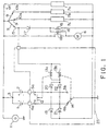
- Fig. 1 shows an electric circuit of a primary embodiment of the present invention.
- Fig. 2 shows an electric circuit of a secondary embodiment of the present invention.
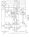
- Fig. 3 shows an electric circuit of a tertiary embodiment of the present invention.
- FIG. 1 shows a primary embodiment of the present invention.
- a primary battery 1 and a secondary battery 2 which are mounted on an internal combustion engine drive vehicle such as an automobile and a ship are provided with a common terminal 3 of (+) polarity and two pairs of independent terminals of (-) polarity one pair (4a, 4b) of which the primary battery 1 is provided with and the other pair (5a, 5b) of which the secondary battery 2 is provide with, and supply an engine starter 6 and loads 7a, 7b, 7c with electricity.
- the loads 7a, 7b are provided with electricity only when a key switch which is an example of an engine switch is turned from its OFF position and connected with a starting point, or a terminal 10a or a terminal 10b.
- a key switch 9 which is an example of an engine switch can be connected with a starting point or disconnected from it by turning, but the key switch 9 may be replaced with a button type switch or the other type switch as an engine switch and the constitution of the engine switch is limited to one type.
- a generator 11 driven by the engine of the internal combustion engine drive vehicle charges the primary battery 1 and the secondary battery 2 in parallel through the common terminal 3 of (+) polarity.
- a primary control contact point 12 is controlled by an electromagnetic coil 13a and can connect the terminal 4a of (-) polarity of the primary battery 1 with the terminal 5a of (-) polarity of the secondary battery 2 or disconnect the former from the latter.
- a secondary control contact point 14 is controlled by an electromagnetic coil 13b and can connect either of terminals 4b, 5b of (-) polarity of the primary battery 1 and the secondary battery 2 alternately with terminals of (-) polarity of the engine starter 6 and the loads 7a, 7b, 7c.
- a tertiary control contact point 18 can connect the primary battery 1 and the secondary battery 2 with the engine starter 6 when the key switch 9 is turned to the starting point and connected with terminals 15, 10a, 10b.
- a control circuit is constituted as described below.
- the primary control contact point 12 When the switch 9 is not connected with a starting point, namely either of terminals 15, 10a, 10b, the primary control contact point 12 is at its OFF position, that is to say, the terminal 4a of (-) polarity of the primary battery 1 is not connected with the terminal 5a of (-) polarity of the secondary battery 2, the secondary control contact point 14 is connected with only one of the terminals 4b, 5b of the primary battery 1 and the secondary battery 2 and hence only one of the primary battery 1 and the secondary battery 2 supplies the load 7c and, as the case may be,the loads 7a, 7b with electricity.
- Diodes 19, 21 are arranged for charging the primary battery 1 and the secondary battery 2 through the generator 11.
- Diodes 20, 22 are connected with the terminals 4b, 5b of (-) polarity of the primary battery 1 and the secondary battery 2 respectively so that they may function as an OR circuit for both the batteries 1,2.
- the generator 11 charges both the batteries 1, 2 in parallel and hence the smooth restarting the engine after having stopped can be realized.
- the main constituents of the control circuit described above which is encircled by a chain line 23 may be put in a case.
- control circuit and both the batteries 1, 2 may be put in a case.
- Fig. 2 shows a circuit of a secondary embodiment of the present invention.
- a fourth control contact point 24 which functions as a one-way diode moves to its ON position a few time late by the aid of a timer 25a and then the primary battery 1 and the secondary battery 2 supply the engine starter 6 with electricity.
- the timer 25a and the fourth control contact point 24 constitute a timer relay 25 which decreases sparks and noise during the ON-OFF action of the secondary control contact point 14 prolonging the life of the secondary control contact point 14.
- the fourth control contact point 24 of the timer relay 25 has an effect of voltage drop remarkably less than the one-way diode 17 shown in the primary embodiment in Fig. 1.
- a switch 26 moving simultaneously with the secondary control contact point 14 lights an indication lamp 27 or 28 to indicate which one of the primary battery 1 and the secondary battery 2 supply the load with electricity.
- Fig. 3 shows a circuit of a tertiary embodiment of the present invention.
- An electromagnetic coil 25b constitutes a delay circuit instead of a timer relay 25 shown in Fig. 2 to make the fourth control contact point 24 move toits ON position.
- the delay circuit comprises a diode 30, resistances 31, 32, diodes 33, 34, a condenser 35 and a power MOS FET 36.
Landscapes
- Engineering & Computer Science (AREA)
- Chemical & Material Sciences (AREA)
- Manufacturing & Machinery (AREA)
- Chemical Kinetics & Catalysis (AREA)
- Electrochemistry (AREA)
- General Chemical & Material Sciences (AREA)
- Power Engineering (AREA)
- Combustion & Propulsion (AREA)
- Mechanical Engineering (AREA)
- General Engineering & Computer Science (AREA)
- Control Of Charge By Means Of Generators (AREA)
- Charge And Discharge Circuits For Batteries Or The Like (AREA)
Abstract
Description
Fig. 1 shows an electric circuit of a primary embodiment of the present invention. Fig. 2 shows an electric circuit of a secondary embodiment of the present invention. Fig. 3 shows an electric circuit of a tertiary embodiment of the present invention.
Claims (3)
- An electric source control device of an internal combustion engine drive vehicle comprisinga primary battery (1) and a secondary battery (2) which are mounted on said internal combustion engine drive vehicle, which supply an engine starter (6) and loads (7a, 7b, 7c) with electricity,a generator (11) which charges said primary battery and said secondary battery which is driven by the engine of said internal combustion engine drive vehicle,a primary control contact point (12) which can connect the terminal (4a) of (-) polarity of said primary battery with the terminal (5a) of (-) polarity of said secondary battery and which can disconnect the former from the latter,a tertiary control contact point (18) which can connect said primary battery and said secondary battery with said engine starter when an engine switch (9) is connected with the starting point, anda control circuit in which when said engine switch is not connected with the starting point said primary control contact point moves to its OFF position to disconnect the terminal of (-) polarity of said primary battery from that of said secondary batteryin which when said engine switch is connected with the starting point, said primary control contact point and said tertiary control contact point move to their ON positions to make both of said batteries supply said engine starter and said loads in parallel with electricity, characterized bya secondary control (14) contact point which can connect either of said terminals of (-) polarity of said primary battery and said secondary battery alternately with terminals of (-) polarity of said engine starter and said loads, said batteries being provided with a common terminal (3) of (+) polarity and two independent terminals of (-) polarity, said secondary control contact point being connected with only one of the terminal of (-) polarity of said primary battery and that of said secondary battery to make only one of said batteries supply said loads with electricity when said engine switch is not connected with the starting point and simultaneously said secondary control contact point being switched to be connected with the one of the terminals of (-)polarity of said primary battery and said secondary battery from the other of the terminals of (-)polarity of said primary battery and said secondary battery when said engine switch is connected with the starting point.
- An electric source control device of an internal combustion engine drive vehicle as claimed in claim 1 wherein a fourth control contact point (24) is set between said engine switch (9) and an electromagnetic coil (25b) for controlling said tertiary control contact point, said fourth control contact point moving to its ON position to make said primary battery and said secondary battery supply said engine starter with electricity a few time later than the actions of said primary control contact point and said secondary control contact point when said engine switch is connected with the starting point.
- An electric source control device of an internal combustion engine drive vehicle as claimed in claim 1 wherein main constituents of said control circuit are put in a case.
Applications Claiming Priority (1)
| Application Number | Priority Date | Filing Date | Title |
|---|---|---|---|
| PCT/JP1993/001468 WO1995010704A1 (en) | 1993-10-13 | 1993-10-13 | Power-supply controller for vehicle propelled by internal combustion engine |
Publications (3)
| Publication Number | Publication Date |
|---|---|
| EP0671561A1 EP0671561A1 (en) | 1995-09-13 |
| EP0671561A4 EP0671561A4 (en) | 1995-11-29 |
| EP0671561B1 true EP0671561B1 (en) | 1998-02-04 |
Family
ID=14070574
Family Applications (1)
| Application Number | Title | Priority Date | Filing Date |
|---|---|---|---|
| EP93922624A Expired - Lifetime EP0671561B1 (en) | 1993-10-13 | 1993-10-13 | Power-supply controller for vehicle propelled by internal combustion engine |
Country Status (7)
| Country | Link |
|---|---|
| US (1) | US5555864A (en) |
| EP (1) | EP0671561B1 (en) |
| KR (2) | KR0149525B1 (en) |
| CN (1) | CN1047654C (en) |
| DE (1) | DE69316920T2 (en) |
| TW (1) | TW249783B (en) |
| WO (1) | WO1995010704A1 (en) |
Families Citing this family (8)
| Publication number | Priority date | Publication date | Assignee | Title |
|---|---|---|---|---|
| NZ264225A (en) * | 1994-08-11 | 1998-07-28 | Glorywin Int Group Ltd | Vehicle battery switch with state of charge sensing circuit |
| US6321707B1 (en) * | 1998-11-12 | 2001-11-27 | James Dunn | Multifunction auxiliary vehicle power and starter system |
| GB2360148A (en) * | 2000-03-06 | 2001-09-12 | Richard Thomas Morgan | Individual charging of cells in a rechargeable battery |
| DE10106622C1 (en) * | 2001-02-13 | 2002-10-10 | Siemens Ag | Circuit arrangement for a generator, in particular an integrated starter generator |
| DE10110940A1 (en) * | 2001-03-07 | 2002-10-02 | Herrmann Alexander | Safety battery system has first state in which first battery can be charged or provide energy source, second battery can only be charged; in second state second battery can provide energy |
| US7240481B2 (en) * | 2005-03-10 | 2007-07-10 | Gm Global Technology Operations, Inc. | Engine load control for reduced cold start emissions |
| CN102447274A (en) * | 2010-10-12 | 2012-05-09 | 皆盈绿电池股份有限公司 | Battery module |
| CN108541244A (en) * | 2016-12-02 | 2018-09-14 | 深圳市仁恒星越科技有限公司 | Engine startup system |
Family Cites Families (16)
| Publication number | Priority date | Publication date | Assignee | Title |
|---|---|---|---|---|
| US1782940A (en) * | 1930-11-25 | Cottbt | ||
| US2730630A (en) * | 1953-07-19 | 1956-01-10 | Bruno Peter | Dual storage battery system |
| US2729750A (en) * | 1954-06-29 | 1956-01-03 | Draper Carson Owen | Motor vehicle electrical system |
| US3477026A (en) * | 1966-08-17 | 1969-11-04 | Leonard Frank Plugge | Motor accumulator circuit |
| JPS5521537B2 (en) * | 1974-07-08 | 1980-06-10 | ||
| JPS5584874U (en) * | 1978-12-06 | 1980-06-11 | ||
| JPS6172044U (en) * | 1984-10-15 | 1986-05-16 | ||
| JPS61118561A (en) * | 1984-11-15 | 1986-06-05 | Yamaha Motor Co Ltd | Engine starting device for vehicle |
| JPS61192642U (en) * | 1985-05-22 | 1986-11-29 | ||
| JPS6268428U (en) * | 1985-10-21 | 1987-04-28 | ||
| US4754730A (en) * | 1986-12-01 | 1988-07-05 | Marc Campagna | Motor vehicle starting system |
| JPH0227158A (en) * | 1988-07-15 | 1990-01-29 | Y Ii C:Kk | Engine starting device for vehicle |
| JPH0443860A (en) * | 1990-06-12 | 1992-02-13 | Secoh Giken Inc | Controller for electricity transmission to load using battery of car |
| JPH0552165A (en) * | 1991-08-21 | 1993-03-02 | Secoh Giken Inc | Electrification control device for load by battery |
| DE4138943C1 (en) * | 1991-11-27 | 1993-05-27 | Robert Bosch Gmbh, 7000 Stuttgart, De | |
| JPH05176464A (en) * | 1991-12-24 | 1993-07-13 | S Internatl Kk | Battery energization control device |
-
1993
- 1993-10-13 WO PCT/JP1993/001468 patent/WO1995010704A1/en not_active Ceased
- 1993-10-13 KR KR1019940701657A patent/KR0149525B1/en not_active Expired - Fee Related
- 1993-10-13 DE DE69316920T patent/DE69316920T2/en not_active Expired - Fee Related
- 1993-10-13 US US08/244,868 patent/US5555864A/en not_active Expired - Fee Related
- 1993-10-13 EP EP93922624A patent/EP0671561B1/en not_active Expired - Lifetime
-
1994
- 1994-04-12 TW TW083103221A patent/TW249783B/zh active
- 1994-05-16 KR KR1019940701657A patent/KR950702677A/en active Granted
- 1994-10-13 CN CN94117116A patent/CN1047654C/en not_active Expired - Fee Related
Also Published As
| Publication number | Publication date |
|---|---|
| CN1109946A (en) | 1995-10-11 |
| DE69316920T2 (en) | 1998-06-04 |
| DE69316920D1 (en) | 1998-03-12 |
| WO1995010704A1 (en) | 1995-04-20 |
| US5555864A (en) | 1996-09-17 |
| KR0149525B1 (en) | 1998-10-01 |
| EP0671561A4 (en) | 1995-11-29 |
| EP0671561A1 (en) | 1995-09-13 |
| CN1047654C (en) | 1999-12-22 |
| TW249783B (en) | 1995-06-21 |
| KR950702677A (en) | 1995-07-29 |
Similar Documents
| Publication | Publication Date | Title |
|---|---|---|
| US5162720A (en) | Vehicle electrical system | |
| JP5356086B2 (en) | Dual battery control system for vehicles | |
| US5563454A (en) | Starting apparatus for vehicles using a subsidiary storage device | |
| JP2536140B2 (en) | Engine starter | |
| JP2003517806A (en) | Battery charge maintenance device and method | |
| US5108848A (en) | Vehicle battery | |
| EP0671561B1 (en) | Power-supply controller for vehicle propelled by internal combustion engine | |
| JPH05336670A (en) | Power supply for vehicle | |
| JP4713244B2 (en) | Dual battery vehicle electrical system | |
| EP3428024A1 (en) | Hybrid vehicle control device | |
| GB2136224A (en) | Vehicle electrical system | |
| EP1295757A2 (en) | Power system for automobiles | |
| SU854285A3 (en) | Device for electric power supply of motor vehicle | |
| JPS5861042A (en) | Power supply device of car | |
| JPH05155296A (en) | Automotive power supply circuit | |
| JPWO1995010704A1 (en) | Power supply control device for internal combustion engine vehicle | |
| KR100233295B1 (en) | Battery discharge monitoring device of the vehicle | |
| JPH09215340A (en) | Inverter circuit | |
| JPH055806Y2 (en) | ||
| JPH03293934A (en) | Power supply device for mounting on vehicle | |
| JPH1111235A (en) | Vehicle power supply | |
| JP4190895B2 (en) | Power supply control circuit for electric retractable mirror device | |
| KR200178370Y1 (en) | Automotive power supply | |
| JPS6330200Y2 (en) | ||
| KR100223617B1 (en) | Battery discharge prevention equipment |
Legal Events
| Date | Code | Title | Description |
|---|---|---|---|
| PUAI | Public reference made under article 153(3) epc to a published international application that has entered the european phase |
Free format text: ORIGINAL CODE: 0009012 |
|
| 17P | Request for examination filed |
Effective date: 19950526 |
|
| AK | Designated contracting states |
Kind code of ref document: A1 Designated state(s): DE FR GB |
|
| A4 | Supplementary search report drawn up and despatched | ||
| AK | Designated contracting states |
Kind code of ref document: A4 Designated state(s): DE FR GB |
|
| 17Q | First examination report despatched |
Effective date: 19961031 |
|
| GRAG | Despatch of communication of intention to grant |
Free format text: ORIGINAL CODE: EPIDOS AGRA |
|
| GRAG | Despatch of communication of intention to grant |
Free format text: ORIGINAL CODE: EPIDOS AGRA |
|
| GRAG | Despatch of communication of intention to grant |
Free format text: ORIGINAL CODE: EPIDOS AGRA |
|
| GRAH | Despatch of communication of intention to grant a patent |
Free format text: ORIGINAL CODE: EPIDOS IGRA |
|
| GRAH | Despatch of communication of intention to grant a patent |
Free format text: ORIGINAL CODE: EPIDOS IGRA |
|
| GRAA | (expected) grant |
Free format text: ORIGINAL CODE: 0009210 |
|
| AK | Designated contracting states |
Kind code of ref document: B1 Designated state(s): DE FR GB |
|
| ET | Fr: translation filed | ||
| REF | Corresponds to: |
Ref document number: 69316920 Country of ref document: DE Date of ref document: 19980312 |
|
| PLBE | No opposition filed within time limit |
Free format text: ORIGINAL CODE: 0009261 |
|
| STAA | Information on the status of an ep patent application or granted ep patent |
Free format text: STATUS: NO OPPOSITION FILED WITHIN TIME LIMIT |
|
| 26N | No opposition filed | ||
| REG | Reference to a national code |
Ref country code: GB Ref legal event code: IF02 |
|
| PGFP | Annual fee paid to national office [announced via postgrant information from national office to epo] |
Ref country code: FR Payment date: 20030917 Year of fee payment: 11 |
|
| PGFP | Annual fee paid to national office [announced via postgrant information from national office to epo] |
Ref country code: GB Payment date: 20031007 Year of fee payment: 11 |
|
| PGFP | Annual fee paid to national office [announced via postgrant information from national office to epo] |
Ref country code: DE Payment date: 20031008 Year of fee payment: 11 |
|
| PG25 | Lapsed in a contracting state [announced via postgrant information from national office to epo] |
Ref country code: GB Free format text: LAPSE BECAUSE OF NON-PAYMENT OF DUE FEES Effective date: 20041013 |
|
| PG25 | Lapsed in a contracting state [announced via postgrant information from national office to epo] |
Ref country code: DE Free format text: LAPSE BECAUSE OF NON-PAYMENT OF DUE FEES Effective date: 20050503 |
|
| GBPC | Gb: european patent ceased through non-payment of renewal fee |
Effective date: 20041013 |
|
| PG25 | Lapsed in a contracting state [announced via postgrant information from national office to epo] |
Ref country code: FR Free format text: LAPSE BECAUSE OF NON-PAYMENT OF DUE FEES Effective date: 20050630 |
|
| REG | Reference to a national code |
Ref country code: FR Ref legal event code: ST |