EP0671508A2 - Pavement - Google Patents
Pavement Download PDFInfo
- Publication number
- EP0671508A2 EP0671508A2 EP95103121A EP95103121A EP0671508A2 EP 0671508 A2 EP0671508 A2 EP 0671508A2 EP 95103121 A EP95103121 A EP 95103121A EP 95103121 A EP95103121 A EP 95103121A EP 0671508 A2 EP0671508 A2 EP 0671508A2
- Authority
- EP
- European Patent Office
- Prior art keywords
- blocks
- plates
- patch according
- tie rods
- corners
- Prior art date
- Legal status (The legal status is an assumption and is not a legal conclusion. Google has not performed a legal analysis and makes no representation as to the accuracy of the status listed.)
- Granted
Links
Images


Classifications
-
- E—FIXED CONSTRUCTIONS
- E01—CONSTRUCTION OF ROADS, RAILWAYS, OR BRIDGES
- E01C—CONSTRUCTION OF, OR SURFACES FOR, ROADS, SPORTS GROUNDS, OR THE LIKE; MACHINES OR AUXILIARY TOOLS FOR CONSTRUCTION OR REPAIR
- E01C5/00—Pavings made of prefabricated single units
- E01C5/005—Individual couplings or spacer elements for joining the prefabricated units
Definitions
- the invention relates to a plaster of blocks or slabs which are laid with a spacing between the joints.
- the paving stones and paving slabs made of concrete with molded spacers which have become known in recent times, have direct contact with one another through this. But they are also held by a joint filling.
- the joint filling originally made of sand, solidifies over time through the ingress of dust, etc.
- Such a paving compound is more resistant to horizontal forces, such as those exerted by starting or braking motor vehicles, due to the direct contact.
- the invention has for its object to further increase the resistance of the patch.
- this purpose is achieved in that the blocks or plates are further connected to one another by tie rods which have recesses in the blocks or plates fitted in them from the surface thereof.
- the tie rods not only absorb any horizontal tensile forces that arise, but also vertical ones. If, according to an advantageous embodiment of the invention, they extend somewhat clampingly through the entire depth or at least half the depth of the blocks or stones, they even create a rigid connection prevents a block or plate from lifting on one side alone.
- the pavement is also secured in the vertical direction.
- the spacers mentioned at the outset can furthermore be integrally formed on the blocks or stones or inserted separately in the joints.
- the tie rods can also serve as spacers or be provided with such.
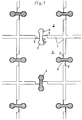
- FIGS. 1 to 15 each show the exemplary embodiments in a top view of the plaster, partly in an exploded isometric view.
- a first and particularly essential embodiment shown in FIGS. 1 to 9 is characterized in that the recesses are from the side surfaces, as in FIGS. 1 to 7, or from the corners, as in FIGS. 8 to 9 Extend the undercut into the blocks or plates and extend from the surface of the blocks or plates with a substantially constant cross-section.
- a plaster of blocks or slabs 2 laid with joints 1, for example made of concrete, can be seen.
- the blocks or plates 2 are provided on each edge in the middle with a recess 3, which extends from the side surface first with a rectangular cross-sectional section 4 and then with an approximately circular cross-sectional section 5 into the material.
- the recesses 3 are formed continuously from the surface to the underside of the blocks or plates 2.
- Two recesses 3 are drawn empty in Fig. 1 above.
- Tie rods 6 are inserted into the other recesses 3 from above. For example, they are made of plastic and are hammered in. They are designed to be complementary to the cross section of the recesses 3 and also fill them in their full height.
- a spacer 7 is formed on the side surface of the block or plate, which defines the joint width.
- the tie rods 6 are in this arrangement in a visible interplay with the spacers 7 consisting of the pressure-resistant material of the blocks or plates 2 as possibly pressure-absorbing elements. A filling of sand, not shown, is introduced into the joints 1.
- the blocks and plates 8 have no spacers 7. Instead, the tie rods 9 are provided with spacers 10. They branch off on both sides of the section of the tie rod 9 lying in the joint.
- the tie rods 11 also have the function of the spacers.
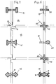
- Fig. 4 shows a form of blocks or plates 12, each having a molded spacer 13 projecting with the joint width at the end of the side surface, so that there is a circumferential support at the joint crossings and the cross joint is interrupted.
- various variants of the recess and the tie rod cross-section following the rectangular cross-sectional section 4 are shown, namely a cross-shaped rectangular cross-sectional section 14, an approximately trapezoidal cross-sectional section 15 and an approximately check-shaped cross-sectional section 16 Spacer 10.
- Fig. 5 shows further variations of recesses and tie rods as well as spacers.
- the undercut by which the tie rod 17 is held is formed by a branch 18 of the cross section of the recess.
- the recess was not created when the stone was formed, but was subsequently cut into an X-shape, preferably at an angle of 30 °.
- a tie rod 20 is shown molded into one block or plate at 19.
- the blocks or plates can always have the tie rods 20 on two adjacent side surfaces and the recesses 3 on the other two adjacent side surfaces. 5 shows various spacers neither molded onto the blocks or plates nor onto the tie rods.
- a web-shaped spacer 21 is shown at the top, which projects into two incisions 22 of the blocks or plates.
- the other arrangement of the same web-shaped spacer is indicated by dashed lines at 23, simply as an insert in the joint or as a branching off of transverse webs on the spacer 21.
- the cross-shaped spacer is here divided into two diagonally colliding, angular spacers 26, each anchored to a block or a plate.
- Fig. 6 shows isometrically on the left the tie rod 6 with the same height as the blocks or plates 2 and on the right the recess 3 with half this height. The same applies accordingly in FIG. 7 on the left for the tie rod with trapezoidal cross-sectional section 15 and branching spacers 10 and on the right for the tie rod with transverse rectangular cross-sectional section 14.
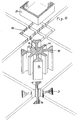
- FIG. 8 to 10 show corner arrangements of the tie rods.
- the crossed tie rods 27 in FIG. 8 at the top right correspond to the arrangement of the tie rods 11 in FIG. 2 on the sides.
- the same crossed tie rods 27 can be seen in FIG. 8 at the top left.
- they are not directly in recesses in the concrete, but in hollow profile parts 28, for example made of cast iron, molded into the blocks or plates.
- Dashed lines indicate a spacer 29 instead inserted at this corner with the cross-section of a hollow check and webs 30 extending from the corners thereof into the joints beveled edges of the blocks or panels.
- the latter function alone is shown in Fig. 8 bottom left with the modification that the spacer 31 there has a ring cross-section.
- tie rods 36 arranged at the corners start from a central body 37, which is at the same time a spacer as a result of abutment on the chamfered corners 38 of the blocks or plates, which are somewhat pulled out here. This corresponds to the spacer 31 with the additions 34 to the tie rod.
- Fig. 9 also shows on the right tie rods 39, which emanate from a full, square-shaped central body 40, which itself is a spacer by abutting the chamfered corners of the blocks or plates, but also has spacing webs 41 protruding into the joints.
- the same arrangement is shown in FIG. 13 below in an isometric representation.
- a combination 42 of tie rod and spacer, which is also to be described, but of a different cross-sectional shape, is shown on the left in FIG. 9.
- the tie rod is in turn seated in the hollow profile parts 43 molded into the blocks or plates.
- These hollow profile parts 43 could be sections of an extruded plastic profile.
- the production the blocks or slabs could be made on the way via large-volume blocks into which the plastic profiles are molded and which are then cut into the blocks or slabs of the plaster.
- the recesses 3 could also be produced by molded tubes which form the circular cross-sectional section 5 and by later cutting the rectangular cross-sectional sections 4, preferably before the large-volume blocks are cut into the blocks or slabs of the plaster.
- FIG. 10 shows a modification: the recesses here are bare cuts 44 of rectangular cross section arranged from the side near the corners of the blocks or plates, and between four adjacent corners of different blocks or plates used tie rods 45 extend into the four joints and from these into a T-shape in the mutually opposite incisions 44, such that they grip each corner in a hook shape in two such incisions with the T-bars 46.
- the corners 47 of the blocks or plates are rounded, the tie rods 45 are connected in an arc shape following the curves.
- the recesses are cuts 48 of rectangular cross-section at the corners of the blocks or plates from above, such that the cuts 48 of four adjacent corners of different blocks or plates complement one another in an annular manner to accommodate an annular tie rod.
- the tie rod 49 is a circular ring.
- the tie rod 50 has the shape of a check.
- the tie rod 51 has the shape of a square. (In the present application, a distinction is made between square and diamond in terms of position.) The same arrangement is shown in an isometric representation in FIG. 13 above.
- the tie rod 52 also has the shape of a square. Spacers 13, enclosed by the square, are arranged at the corners of the blocks or plates in the configuration described in relation to FIG. 4.
- annular tie rods 49 to 51 in particular the square tie rod 51, in their incisions 48 also allows the absorption of compressive forces. Without additional spacers as in Fig. 12 bottom right, these tie rods 49 to 51 will be made of steel.
- the annular tie rod 52 according to FIG. 11 could be made of plastic. It does not need to absorb compressive forces in the ring, since it is provided with spacers 53 and a central body 54 arranged in the manner of spokes, which lie in the joints and the joint crossing.
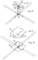
- FIGS. 14 and 15 Again a new variant of the recess and tie rod and the engagement of the tie rod are shown in FIGS. 14 and 15 in an isometric view.
- the blocks or plates have spacers 13 formed near their ends, each projecting into the joint on one side, in the configuration already known and described in plan view from FIG. 4. Above the spacers 13, however, the flat recess 55 or 56 is arranged, into which the tie rod 57 or 58, which bridges the four corners, is inserted.
- the tie rod 57 in FIG. 14 the bridging has the shape of a cross 59 lying in the alignment of the joints.
- the tie rod 58 in FIG. 15 it has the shape of a plate 60 which extends beyond it.
- fingers 61 angled like a staple grasp each in the joints behind a spacer 13.
- a bolt 62 arranged centrally under the cross 59 or the plate 60 also fits into the gap 63 between the four spacers 13.
- the bolt 62 has an annular profile 64 from barbed cross section of the rings. It can e.g. be applied by a rubber covering.
- the entire bolt 62 is made of a similarly soft material and, not shown, is screwed to the cross 59 or the plate 60.
- the bolt 62 can also be inserted first, for example driven in, and then the remaining tie rod can be placed and held by the screw connection with the bolt.
- Similar tie rods could also grip fingers or angled fingers bridging from adjacent blocks or plates at the sides or corners in these adapted recesses in the recesses of the blocks or plates receiving the tie rods. Spacers molded onto the blocks or plates could also be present.
- the recesses extend from the sides or corners in principle without undercut into the blocks or plates and from the surface of the blocks or plates made with a substantially constant cross-section, and in this case clamp the tie rods in the recesses.
- tie rods are then expediently strong blocks made of a harder rubber with a barb profile on their clamping surfaces. They can be hammered into the recesses.
- the other tie rods consist, for example, of steel or other metal, wood, plastic, in particular recycled plastic, or also of rubber.
- Concrete is primarily used for the blocks or slabs, but by no means exclusively. Likewise possible are e.g. ceramic material or recycled plastic.
Abstract
Description
Die Erfindung betrifft ein Pflaster aus Blöcken oder Platten, die mit durch Abstandhalter gesichertem Fugenabstand verlegt sind.The invention relates to a plaster of blocks or slabs which are laid with a spacing between the joints.
Die in jüngerer Zeit bekanntgewordenen Pflastersteine und Pflasterplatten aus Beton mit angeformten Abstandhaltern haben durch diese unmittelbare Berührung miteinander. Sie sind aber außerdem durch eine Fugenfüllung gehalten. Die ursprünglich aus Sand bestehende Fugenfüllung verfestigt sich im Laufe der Zeit durch Eindringen von Staub usw..
Ein solcher Pflasterverbund ist durch die unmittelbare Berührung widerstandsfähiger gegenüber Horizontalkräften, wie sie z.B. durch anfahrende oder bremsende Kraftfahrzeuge ausgeübt werden.The paving stones and paving slabs made of concrete with molded spacers, which have become known in recent times, have direct contact with one another through this. But they are also held by a joint filling. The joint filling, originally made of sand, solidifies over time through the ingress of dust, etc.
Such a paving compound is more resistant to horizontal forces, such as those exerted by starting or braking motor vehicles, due to the direct contact.
Der Erfindung liegt die Aufgabe zugrunde, die Widerstandsfähigkeit des Pflasters weiter zu erhöhen.The invention has for its object to further increase the resistance of the patch.
Gemäß der Erfindung wird dieser Zweck dadurch erfüllt, daß die Blöcke oder Platten ferner durch Zuganker miteinander verbunden sind, die in ihnen angepaßte Ausnehmungen der Blöcke oder Platten von deren Oberfläche her eingesetzt sind.According to the invention, this purpose is achieved in that the blocks or plates are further connected to one another by tie rods which have recesses in the blocks or plates fitted in them from the surface thereof.
Die Zuganker nehmen nicht nur etwa entstehende waagerechte Zugkräfte auf, sondern damit zugleich auch senkrechte. Wenn sie sich nach vorteilhafter Ausgestaltung der Erfindung etwas klemmend durch die gesamte Tiefe oder wenigstens die halbe Tiefe der Blöcke oder Steine erstrecken, schaffen sie sogar eine biegesteife Verbindung, die verhindert, daß ein Block oder eine Platte allein sich einseitig anheben kann. Der Pflasterverbund wird auch in senkrechter Richtung gesichert.
Die eingangs erwähnten Abstandhalter können weiterhin an den Blöcken oder Steinen angeformt oder gesondert in die Fugen eingelegt sein. Die Zuganker können aber auch zugleich als Abstandhalter dienen oder mit solchen versehen sein.The tie rods not only absorb any horizontal tensile forces that arise, but also vertical ones. If, according to an advantageous embodiment of the invention, they extend somewhat clampingly through the entire depth or at least half the depth of the blocks or stones, they even create a rigid connection prevents a block or plate from lifting on one side alone. The pavement is also secured in the vertical direction.
The spacers mentioned at the outset can furthermore be integrally formed on the blocks or stones or inserted separately in the joints. The tie rods can also serve as spacers or be provided with such.
Zahlreiche mögliche Ausgestaltungen der Erfindung sollen im folgenden anhand von Ausführungsbeispielen dargestellt werden.Numerous possible refinements of the invention are to be illustrated below using exemplary embodiments.
Die Zeichnungen Fig. 1 bis 15 geben die Ausführungsbeispiele jeweils in Draufsicht auf das Pflaster, teilweise in auseinandergezogener isometrischer Darstellung, wieder.The drawings FIGS. 1 to 15 each show the exemplary embodiments in a top view of the plaster, partly in an exploded isometric view.
Eine erste und besonders wesentliche, in Fig. 1 bis 9 dargestellte Ausführungsform kennzeichnet sich dadurch, daß sich die Ausnehmungen von den Seitenflächen her, wie in Fig. 1 bis 7, oder von den Ecken her, wie in Fig. 8 bis 9, mit Hinterschneidung in die Blöcke oder Platten hinein erstrecken und von der Oberfläche der Blöcke oder Platten aus mit im wesentlichen gleichbleibendem Querschnitt in die Tiefe erstrecken.A first and particularly essential embodiment shown in FIGS. 1 to 9 is characterized in that the recesses are from the side surfaces, as in FIGS. 1 to 7, or from the corners, as in FIGS. 8 to 9 Extend the undercut into the blocks or plates and extend from the surface of the blocks or plates with a substantially constant cross-section.
In Fig. 1 ist ein Pflaster aus mit Fugen 1 verlegten Blöcken oder Platten 2, beispielsweise aus Beton, zu erkennen.
Die Blöcke oder Platten 2 sind an jedem Rand in der Mitte mit einer Ausnehmung 3 versehen, die sich von der Seitenfläche her zunächst mit einem rechteckigen Querschnittsabschnitt 4 und dann mit einem etwa kreisförmigen Querschnittsabschnitt 5 in das Material hinein erstreckt. Die Ausnehmungen 3 sind mit diesem Querschnitt durchgehend von der Oberfläche bis zur Unterseite der Blöcke oder Platten 2 ausgebildet. Zwei Ausnehmungen 3 sind in Fig. 1 oben leer gezeichnet. In die anderen Ausnehmungen 3 sind von oben her Zuganker 6 eingesetzt. Beispielsweise bestehen sie aus Kunststoff und sind eingeschlagen. Sie sind komplementär zu dem Querschnitt der Ausnehmungen 3 gestaltet und füllen diese auch in der Höhe voll aus.In Fig. 1, a plaster of blocks or
The blocks or
Jeweils auf der einen Seite der Ausnehmung 3 ist unmittelbar neben dieser ein Abstandhalter 7 an der Seitenfläche des Blockes oder der Platte geformt, der die Fugenbreite vorgibt.
Die Zuganker 6 stehen bei dieser Anordnung in sichtbarem Wechselspiel mit den aus dem druckfesten Material der Blöcke oder Platten 2 bestehenden Abstandhaltern 7 als ggf. druckaufnehmenden Elementen.
In die Fugen 1 ist eine nicht dargestellte Füllung aus Sand eingebracht.In each case on one side of the
The
A filling of sand, not shown, is introduced into the
In Fig. 2 haben die Blöcke und Platten 8 keine Abstandhalter 7. Stattdessen sind die Zuganker 9 mit Abstandhaltern 10 versehen. Sie zweigen auf dem in der Fuge liegenden Abschnitt des Zugankers 9 beidseitig von diesem ab.2, the blocks and plates 8 have no
Nach Fig. 3 haben die Zuganker 11 zugleich die Funktion der Abstandhalter.3, the
Fig. 4 zeigt eine Form von Blöcken oder Platten 12, die jeweils einen mit der Fugenbreite vorspringenden angeformten Abstandhalter 13 am Ende der Seitenfläche aufweisen, so daß sich an den Fugenkreuzungen eine umlaufende Abstützung ergibt und die Kreuzfuge unterbrochen ist. Im übrigen sind hier verschiedene Varianten des Ausnehmungs- und des Zugankerquerschnitts im Anschluß an den rechteckigen Querschnittsabschnitt 4 dargestellt, nämlich ein quergestellter rechteckiger Querschnittsabschnitt 14, ein etwa trapezförmiger Querschnittsabschnitt 15 und ein etwa karoförmiger Querschnittsabschnitt 16. Gestrichelt angedeutet ist wiederum die Möglichkeit an den Zugankern abzweigender Abstandhalter 10.Fig. 4 shows a form of blocks or
Fig. 5 zeigt weitere Variationen von Ausnehmungen und Zugankern sowie von Abstandhaltern.
Nach der unteren Darstellung ist die Hinterschneidung, durch die der Zuganker 17 gehalten ist, durch eine Verzweigung 18 des Querschnitts der Ausnehmung gebildet. Die Ausnehmung ist nicht bei der Formung des Steines entstanden, sondern nachher X-förmig eingeschnitten, vorzugsweise unter einem Winkel von 30°.
In der Mitte der Fig. 5 ist ein in den einen Block oder die eine Platte bei 19 eingeformter Zuganker 20 gezeigt. Bei dieser Variante können die Blöcke oder Platten immer an zwei nebeneinanderliegenden Seitenflächen die Zuganker 20 und an den anderen beiden nebeneinanderliegenden Seitenflächen die Ausnehmungen 3 aufweisen.
Im übrigen zeigt Fig. 5 verschiedene weder an die Blöcke oder Platten noch an die Zuganker angeformte Abstandhalter. Oben ist ein stegförmiger Abstandhalter 21 dargestellt, der in zwei Einschnitte 22 der Blöcke oder Platten ragt. Gestrichelt angedeutet ist bei 23 die andere Anordnung eines gleichen stegförmigen Abstandhalters einfach als Einlage in der Fuge oder als Abzweigung von Querstegen an dem Abstandhalter 21. Darunter findet sich ein an den Ecken der Blöcke oder Platten angesetzter kreuzförmigar Abstandhalter 24. Er ist, wie bei 25 angedeutet, an dem einen der Blöcke oder der einen der Platten, die hier zusammenstoßen, verankert. Weiter unten ist eine im ganzen gleiche Anordnung zu erkennen. Der kreuzförmige Abstandhalter ist hier jedoch aufgeteilt in zwei diagonal zusammenstoßende, jeweils an einem Block oder einer Platte verankerte, winkelförmige Abstandhalter 26.Fig. 5 shows further variations of recesses and tie rods as well as spacers.
According to the lower illustration, the undercut by which the
In the middle of FIG. 5, a
5 shows various spacers neither molded onto the blocks or plates nor onto the tie rods. A web-
Fig. 6 zeigt isometrisch links den Zuganker 6 mit gleicher Höhe wie die Blöcke oder Platten 2 und rechts die Ausnehmung 3 mit der Hälfte dieser Höhe.
Entsprechendes gilt in Fig. 7 links für den Zuganker mit trapezförmigen Querschnittsabschnitt 15 und abzweigenden Abstandhaltern 10 und rechts für den Zuganker mit quergestelltem rechtwinkligem Querschnittsabschnitt 14.Fig. 6 shows isometrically on the left the
The same applies accordingly in FIG. 7 on the left for the tie rod with
Fig. 8 bis 10 zeigen Eckanordnungen der Zuganker.
Die gekreuzten Zuganker 27 in Fig. 8 oben rechts entsprechen der Anordnung der Zuganker 11 in Fig. 2 an den Seiten.
In Fig. 8 oben links sind die gleichen gekreuzten Zuganker 27 zu erkennen. Sie stecken jedoch nicht unmittelbar in Ausnehmungen des Betons, sondern in in die Blöcke oder Platten eingeformten Hohlprofilteilen 28 z.B. aus Gußeisen. Gestrichelt angedeutet ist ein stattdessen an dieser Ecke eingesetzter Abstandhalter 29 mit dem Querschnitt eines hohlen Karos und von dessen Ecken in die Fugen sich erstreckenden Stegen 30. Die Funktion des Abstandhalters haben nicht nur die Stege 30, sondern auch die Außenseiten des Karos in Wechselwirkung mit den abgeschrägten Kanten der Blöcke oder Platten.
Die letztere Funktion allein ist in Fig. 8 unten links dargestellt mit der Abwandlung, daß der dortige Abstandhalter 31 einen Ringquerschnitt aufweist. Er ist auf der Ecke zentriert gehalten durch in Einschnitten 32 der Blöcke oder Platten steckende Flügel 33. Gestrichelt angedeutet sind an den Enden der Flügel Ergänzungen 34 des Abstandhalters 31 zu einem Zuganker. Mit gestrichelt angedeuteten Fortsetzungen 35 der Flügel 33 in den Ringquerschnitt hinein könnte dieser ausgefüllt werden.8 to 10 show corner arrangements of the tie rods.
The
The same
The latter function alone is shown in Fig. 8 bottom left with the modification that the
In Fig. 8 unten rechts gehen an den Ecken angeordnete Zuganker 36 von einem Zentralkörper 37 aus, der durch Anstoß an den abgeschrägten, hier aber dabei noch etwas herausgezogenen, Ecken 38 der Blöcke oder Platten zugleich Abstandhalter ist. Dies entspricht dem Abstandhalter 31 mit den Ergänzungen 34 zum Zuganker.In FIG. 8, at the bottom right,
Fig. 9 zeigt rechts gleichfalls Zuganker 39, die von einem, hier vollen, karoförmigen Zentralkörper 40 ausgehen, der durch Anstoß an den abgeschrägten Ecken der Blöcke oder Platten selbst Abstandhalter ist, darüber hinaus aber in die Fugen hineinragende abstandhaltende Stege 41 aufweist. Die gleiche Anordnung zeigt Fig. 13 unten in isometrischer Darstellung.
Eine ebenso zu beschreibende Kombination 42 von Zuganker und Abstandhalter, lediglich von anderer Querschnittsform, ist in Fig. 9 links dargestellt. Der Zuganker sitzt wiederum in in die Blöcke oder Platten eingeformten Hohlprofilteilen 43. Diese Hohlprofilteile 43 könnten Abschnitte eines stranggepreßten Kunststoffprofils sein. Die Herstellung der Blöcke oder Platten könnte hier auf dem Wege über großvolumige Blöcke erfolgen, in die die Kunststoffprofile eingeformt werden und die anschließend in die Blöcke oder Platten des Pflasters zerschnitten werden.
Analog könnten auch die Ausnehmungen 3 durch eingeformte Rohre, die den kreisförmigen Querschnittsabschnitt 5 bilden, erzeugt werden und durch späteres Einschneiden der rechteckigen Querschnittsabschnitte 4, vorzugsweise vor dem Zerschneiden der großvolumigen Blöcke in die Blöcke oder Platten des Pflasters.Fig. 9 also shows on the
A
Analogously, the
Während alle bisherigen Ausführungsformen eine hinterschnittene Ausnehmung 3 zur Grundlage haben, zeigt Fig. 10 eine Abwandlung: Die Ausnehmungen sind hier nahe den Ecken der Blöcke oder Platten angeordnete bloße Einschnitte 44 rechteckigen Querschnitts von der Seite her, und zwischen vier benachbarten Ecken verschiedener Blöcke oder Platten eingesetzte Zuganker 45 erstrecken sich in die vier Fugen und von diesen T-förmig in die jeweils einander gegenüberliegenden Einschnitte 44 hinein, derart, daß sie mit den T-Balken 46 jede Ecke hakenförmig in zwei solchen Einschnitten fassen. Die Ecken 47 der Blöcke oder Platten sind gerundet, die Zuganker 45 sind den Rundungen folgend bogenförmig verbunden.While all previous embodiments are based on an
Fig. 11 bis 13 zeigen eine weitere Form des Eingriffs von Zugankern in Ausnehmungen. Die Ausnehmungen sind Einschnitte 48 rechteckigen Querschnitts an den Ecken der Blöcke oder Platten von oben her, derart, daß sich die Einschnitte 48 von vier benachbarten Ecken verschiedener Blöcke oder Platten ringförmig ergänzen zur Aufnahme eines ringförmigen Zugankers.
Nach Fig. 12 links unten ist der Zuganker 49 ein Kreisring.
Nach Fig. 12 links oben hat der Zuganker 50 die Form eines Karos.
Nach Fig. 12 rechts oben hat der Zuganker 51 die Form eines Quadrats. (In der vorliegenden Anmeldung ist zwischen Quadrat und Karo nach der Stellung unterschieden.) Die gleiche Anordnung zeigt Fig. 13 oben in isometrischer Darstellung.11 to 13 show a further form of engagement of tie rods in recesses. The recesses are
12, the
12, the
12, the
Nach Fig. 12 rechts unten hat der Zuganker 52 gleichfalls die Form eines Quadrats. An den Ecken der Blöcke oder Platten sind hier, von dem Quadrat eingeschlossene, Abstandhalter 13 in der zu Fig. 4 beschriebenen Konfiguration angeordnet.According to Fig. 12 bottom right, the
Die Art des Eingriffs der ringförmigen Zuganker 49 bis 51, insbesondere des quadratischen Zugankers 51, in ihre Einschnitte 48 erlaubt auch die Aufnahme von Druckkräften. Ohne zusätzliche Abstandhalter wie in Fig. 12 unten rechts wird man diese Zuganker 49 bis 51 aus Stahl herstellen.The type of engagement of the
Aus Kunststoff hergestellt sein könnte der ringförmige Zuganker 52 gemäß Fig. 11. Er braucht Druckkräfte nicht in dem Ring aufzunehmen, da er mit speichenartig angeordneten Abstandhaltern 53 und einem Zentralkörper 54 versehen ist, die in den Fugen und der Fugenkreuzung liegen.The
Wiederum eine neue Variante von Ausnehmung und Zuganker und dem Eingriff des Zugankers zeigen Fig. 14 und 15 in auseinandergezogener, isometrischer Darstellung.Again a new variant of the recess and tie rod and the engagement of the tie rod are shown in FIGS. 14 and 15 in an isometric view.
Die Blöcke oder Platten weisen nahe ihren Enden angeformte, jeweils nach einer Seite in die Fuge vorspringende Abstandhalter 13 auf in der aus Fig. 4 in der Draufsicht bereits bekannten und beschriebenen Konfiguration. Über den Abstandhaltern 13 ist hier jedoch die, flache, Ausnehmung 55 bzw. 56 angeordnet, in die der Zuganker 57 bzw. 58, die vier Ecken überbrückend, eingesetzt ist. Die Überbrückung hat bei dem Zuganker 57 in Fig. 14 die Form eines in der Flucht der Fugen liegenden Kreuzes 59. Bei dem Zuganker 58 in Fig. 15 hat sie die Form einer darüber hinaus sich erstreckenden Platte 60. Von dem Kreuz 59 und der Platte 60 krampenförmig abgewinkelte Finger 61 fassen in den Fugen jeweils hinter einen Abstandhalter 13. Ein mittig unter dem Kreuz 59 bzw. der Platte 60 angeordneter Bolzen 62 faßt außerdem in die Lücke 63 zwischen den vier Abstandhaltern 13. Der Bolzen 62 ist mit einer Ringprofilierung 64 von widerhakenförmigem Querschnitt der Ringe versehen. Sie kann z.B. durch einen Gummibelag aufgebracht sein. Vorzugsweise besteht jedoch der ganze Bolzen 62 aus einem ähnlich weichen Material, und er ist, nicht gezeichnet, mit dem Kreuz 59 bzw. der Platte 60 verschraubt. So kann der Bolzen 62 auch zuerst eingesetzt, beispielsweise eingeschlagen werden, und dann der übrige Zuganker gesetzt und durch die Verschraubung mit dem Bolzen gehalten werden.The blocks or plates have spacers 13 formed near their ends, each projecting into the joint on one side, in the configuration already known and described in plan view from FIG. 4. Above the
Gestrichelt ist in Fig. 15 eine andere Form bzw. Anordnung der Platte 60 und der zugehörigen Ausnehmung 56 gezeichnet.Another shape or arrangement of the
Ähnliche Zuganker könnten auch mit von benachbarte Blöcke oder Platten an den Seiten oder Ecken überbrückenden Stegen oder Platten krampenförmig abgewinkelten Fingern in diesen angepaßte Vertiefungen der die Zuganker aufnehmenden Ausnehmungen der Blöcke oder Platten fassen. An den Blöcken oder Platten angeformte Abstandhalter könnten zusätzlich vorhanden sein.Similar tie rods could also grip fingers or angled fingers bridging from adjacent blocks or plates at the sides or corners in these adapted recesses in the recesses of the blocks or plates receiving the tie rods. Spacers molded onto the blocks or plates could also be present.
Eine weitere in den Zeichnungen nicht dargestellte Ausführungsform besteht darin, daß die Ausnehmungen sich von den Seiten oder Ecken her im Prinzip ohne Hinterschneidung in die Blöcke oder Platten hinein erstrecken und von der Oberfläche der Blöcke oder Platten aus mit im wesentlichen gleichbleibendem Querschnitt in die Tiefe erstrecken und in diesem Falle die Zuganker in den Ausnehmungen klemmen.Another embodiment, not shown in the drawings, is that the recesses extend from the sides or corners in principle without undercut into the blocks or plates and from the surface of the blocks or plates made with a substantially constant cross-section, and in this case clamp the tie rods in the recesses.
Die Zuganker sind dann zweckmäßigerweise kräftige Klötze aus einem härteren Gummi mit einem Widerhakenprofil an ihren Klemmflächen. Sie können in die Ausnehmungen eingeschlagen werden.The tie rods are then expediently strong blocks made of a harder rubber with a barb profile on their clamping surfaces. They can be hammered into the recesses.
Die anderen Zuganker bestehen beispielsweise aus Stahl oder anderem Metall, Holz, Kunststoff, insbesondere Recycling-Kunststoff, oder auch aus Gummi.The other tie rods consist, for example, of steel or other metal, wood, plastic, in particular recycled plastic, or also of rubber.
Für die Blöcke oder Platten kommt in erster Linie Beton in Betracht, aber keineswegs ausschließlich. Gleichfalls möglich sind z.B. keramisches Material oder Recycling-Kunststoff.Concrete is primarily used for the blocks or slabs, but by no means exclusively. Likewise possible are e.g. ceramic material or recycled plastic.
Claims (31)
dadurch gekennzeichnet,
daß die Blöcke oder Platten (2;8;12) ferner durch Zuganker (6;9;14;15;16;17;20;27;36;39;42;45;49;50;51;52;57;58) miteinander verbunden sind, die in ihnen angepaßte Ausnehmungen (3;18;44;48;55;56) der Blöcke oder Platten (2;8;12) von deren Oberfläche her eingesetzt sind.Plaster of blocks or slabs (2; 8; 12), which are joined by spacers (7; 10; 13; 21; 23; 24; 26; 29.30; 31; 37; 40.41; 42; 53.54) secure joint spacing are installed,
characterized,
that the blocks or plates (2; 8; 12) further by tie rods (6; 9; 14; 15; 16; 17; 20; 27; 36; 39; 42; 45; 49; 50; 51; 52; 57; 58) are connected to one another, the recesses (3; 18; 44; 48; 55; 56) of the blocks or plates (2; 8; 12) which are adapted in them are inserted from their surface.
dadurch gekennzeichnet,
daß (Fig. 1 bis 9) die Ausnehmungen (3) sich von den Seitenflächen oder Ecken her mit Hinterschneidung (5;14;15;16;18) in die Blöcke oder Platten (2;8;12) hinein erstrecken und von der Oberfläche der Blöcke oder Platten (2;8;12) aus mit im wesentlichen gleichbleibendem Querschnitt in die Tiefe erstrecken.Patch according to claim 1,
characterized,
that (Fig. 1 to 9) the recesses (3) from the side surfaces or corners with undercut (5; 14; 15; 16; 18) into the blocks or plates (2; 8; 12) and from the Extend the surface of the blocks or plates (2; 8; 12) in depth with a substantially constant cross section.
dadurch gekennzeichnet,
daß (Fig. 1 bis 4) die Hinterschneidung durch einen an einen rechteckigen Querschnittsabschnitt (4) anschließenden etwa kreisförmigen (5), trapezförmigen (15), karoförmigen (16) oder quergestellten rechteckigen (14) Querschnittsabschnitt gebildet ist.Patch according to claim 2,
characterized,
that (FIGS. 1 to 4) the undercut is formed by an approximately circular (5), trapezoidal (15), square (16) or transverse rectangular (14) cross-sectional section adjoining a rectangular cross-sectional section (4).
dadurch gekennzeichnet,
daß (Fig. 5) die Hinterschneidung durch eine, vorzugsweise X-förmig eingeschnittene, Verzweigung (18) des Querschnitts gebildet ist.Patch according to claim 2,
characterized,
that (Fig. 5) the undercut is formed by a, preferably X-shaped cut, branching (18) of the cross section.
dadurch gekennzeichnet,
daß (Fig. 10) die Ausnehmungen nahe den Ecken der Blöcke oder Platten angeordnete Einschnitte (14), vorzugsweise rechteckigen Querschnitts, von der Seite her sind und zwischen vier benachbarten Ecken verschiedener Blöcke oder Platten eingesetzte Zuganker (45) sich in die vier Fugen und von diesen jeweils in zwei solche Einschnitte (44) hinein erstrecken, derart, daß sie jede Ecke hakenförmig (46) in zwei solchen Einschnitten (44) fassen.Patch according to claim 1,
characterized,
that (Fig. 10) the recesses near the corners of the blocks or plates arranged incisions (14), preferably rectangular cross-section, are from the side and between four adjacent corners of different blocks or plates used tie rods (45) in the four joints and of these in two each Incisions (44) extend in such a way that they grip each corner hook-shaped (46) in two such incisions (44).
dadurch gekennzeichnet,
daß die Zuganker (45) sich T-förmig (46) in zwei gegenüberliegende Einschnitte (44) verschiedener Blöcke oder Platten hinein erstrecken.Patch according to claim 5,
characterized,
that the tie rods (45) extend in a T-shape (46) into two opposite incisions (44) of different blocks or plates.
dadurch gekennzeichnet,
daß die Ecken (47) der Blöcke oder Platten gerundet und die Zuganker bogenförmig verbunden sind.Patch according to claim 5 or 6,
characterized,
that the corners (47) of the blocks or plates are rounded and the tie rods are connected in an arc.
dadurch gekennzeichnet,
daß (Fig. 11 bis 13) die Ausnehmungen an den Ecken der Blöcke oder Platten angeordnete Einschnitte (48), vorzugsweise rechteckigen Querschnitts, von oben her derart sind, daß sich die Einschnitte (48) von vier benachbarten Ecken verschiedener Blöcke oder Platten ringförmig ergänzen zur Aufnahme eines ringförmigen Zugankers (49-52).Patch according to claim 1,
characterized,
that (Fig. 11 to 13) the recesses at the corners of the blocks or plates arranged incisions (48), preferably rectangular cross-section, are from above such that the incisions (48) of four adjacent corners of different blocks or plates complement each other in a ring for receiving an annular tie rod (49-52).
dadurch gekennzeichnet,
daß die Ringform ein Kreisring (49,52) ist.Patch according to claim 8,
characterized,
that the ring shape is a circular ring (49.52).
dadurch gekennzeichnet,
daß die Ringform ein Quadrat (51) mit in den Blöcken oder Platten liegenden Ecken ist.Patch according to claim 8,
characterized,
that the ring shape is a square (51) with corners lying in the blocks or plates.
dadurch gekennzeichnet,
daß die Ringform ein Quadrat mit in den Fugen liegenden Ecken (Karo 50) ist.Patch according to claim 8,
characterized,
that the ring shape is a square with corners in the joints (diamond 50).
dadurch gekennzeichnet,
daß (Fig. 14,15) die Blöcke oder Platten nahe ihren Ecken angeformte, jeweils nach einer Seite in die Fuge vorspringende Abstandhalter (13) aufweisen und die Zuganker (57;58) krampenartig mit von einer in die Ausnehmung (55;56) eingesetzten Überbrückung (59;60) der vier Ecken aus abgewinkelten Fingern (61) in den Fugen hinter jeweils einen Abstandhalter (13) fassen.Patch according to claim 1,
characterized,
that (Fig. 14, 15) the blocks or plates have molded-on spacers (13) near their corners, each projecting into the joint on one side, and the tie rods (57; 58) are cramped with one into the recess (55; 56) Grip the bridging (59; 60) of the four corners from angled fingers (61) in the joints behind a spacer (13).
dadurch gekennzeichnet,
daß die Zuganker (57,58) ferner mit einem mittig angeordneten Bolzen (62) von quadratischem Querschnitt in die Lücke (63) zwischen den vier Abstandhaltern (13) fassen.Patch according to claim 12,
characterized,
that the tie rods (57, 58) also reach with a centrally arranged bolt (62) of square cross-section into the gap (63) between the four spacers (13).
dadurch gekennzeichnet,
daß der Bolzen (62) aus weichem Material besteht oder mit weichem Material belegt ist und an seinem Umfang eine Ringprofilierung (64), vorzugsweise von widerhakenförmigem Querschnitt der Ringe, aufweist.Patch according to claim 13,
characterized,
that the bolt (62) consists of soft material or is covered with soft material and has a ring profile (64) on its circumference, preferably of barb-shaped cross section of the rings.
dadurch gekennzeichnet,
daß der übrige Zuganker (59-61) mit dem, vorher zu setzenden, Bolzen (62) verschraubbar ist.Patch according to claim 13 or 14,
characterized,
that the remaining tie rod (59-61) can be screwed to the bolt (62) to be set beforehand.
dadurch gekennzeichnet,
daß die Überbrückung die Form einer Platte (60) oder eines auf die Flucht der Fugen beschränkten Kreuzes (59) hat.Patch according to one of claims 12 to 15,
characterized,
that the bridging is in the form of a plate (60) or a cross (59) restricted to the alignment of the joints.
dadurch gekennzeichnet,
daß die Zuganker mit von benachbarte Blöcke oder Platten an den Seiten oder Ecken überbrückenden Stegen oder Platten krampenförmig abgewinkelten Fingern in diesen angepaßte Vertiefungen der die Zuganker aufnehmenden Ausnehmungen der Blöcke oder Platten fassen.Patch according to claim 1,
characterized,
that the tie rods with fingers or plates bridging from adjacent blocks or plates bridging at the sides or corners in a cramp-like manner grip recesses in the recesses of the blocks or plates receiving the tie rods.
dadurch gekennzeichnet,
daß die Ausnehmungen sich von den Seitenflächen oder Ecken her in die Blöcke oder Platten hinein erstrecken und von der Oberfläche der Blöcke oder Platten aus mit im wesentlichen gleichbleibendem Querschnitt in die Tiefe erstrecken und die Zuganker in den Ausnehmungen klemmen.Patch according to claim 1,
characterized,
that the recesses extend from the side surfaces or corners into the blocks or plates and extend from the surface of the blocks or plates with a substantially constant cross-section in depth and clamp the tie rods in the recesses.
dadurch gekennzeichnet,
daß die Zuganker aus Gummi oder einem anderen elastischen Material bestehen.Patch according to claim 18,
characterized,
that the tie rods are made of rubber or another elastic material.
dadurch gekennzeichnet,
daß die Zuganker mit Widerhakenprofil an ihren Klemmflächen ausgebildet sind.Patch according to claim 18 or 19,
characterized,
that the tie rods are designed with barb profile on their clamping surfaces.
dadurch gekennzeichnet,
daß die Zuganker in die Ausnehmungen eingeschlagen sind.Patch according to one of claims 18 to 20,
characterized,
that the tie rods are hammered into the recesses.
dadurch gekennzeichnet,
daß die Zuganker (19) in einem der Blöcke bzw. einer der Platten eingeformt sind.Patch according to one of claims 2 to 4,
characterized,
that the tie rods (19) are molded into one of the blocks or one of the plates.
dadurch gekennzeichnet,
daß die Zuganker (9) die Abstandhalter (10) aufweisen als in den Fugen ein- oder beidseitig von ihnen abzweigende Querstege.Patch according to one of claims 1 to 22,
characterized,
that the tie rods (9) have the spacers (10) as transverse webs branching from them on one or both sides of them.
dadurch gekennzeichnet,
daß an den Ecken angeordnete Zuganker (36;39;42) von einem auf der Fugenkreuzung sitzenden Zentralkörper (37;40) ausgehen, der durch Anstoß an den abgeschrägten Ecken (38) der Blöcke oder Platten selbst Abstandhalter ist und/oder in die Fugen hineinragende Stege (41) als Abstandhalter aufweist.Patch according to one of claims 1 to 21,
characterized,
that tie rods (36; 39; 42) arranged at the corners start from a central body (37; 40) seated on the joint crossing, which itself is a spacer due to abutment at the chamfered corners (38) of the blocks or plates and / or into the joints protruding webs (41) as a spacer.
dadurch gekennzeichnet,
daß die Blöcke oder Platten (2) angeformte, jeweils nach einer Seite in die Fuge (1) vorspringende Abstandhalter (7) neben den Zugankern (6) aufweisen.Patch according to one of claims 1 to 22,
characterized,
that the blocks or plates (2) have molded-on spacers (7) projecting into the joint (1) on one side in addition to the tie rods (6).
dadurch gekennzeichnet,
daß die Blöcke oder Platten an den Seitenflächen angesetzte stegförmige (21;23) oder an den Ecken angesetzte kreuzförmige (24;26) Abstandhalter aufweisen, die vorzugsweise an einem der Blöcke oder einer der Platten verankert (25) sind.Patch according to one of claims 1 to 22,
characterized,
that the blocks or plates have web-shaped (21; 23) or cross-shaped (24; 26) spacers attached to the side surfaces, which are preferably anchored (25) to one of the blocks or one of the plates.
dadurch gekennzeichnet,
daß sich die Ausnehmungen (3) mindestens bis in die halbe Tiefe der Blöcke oder Platten (1) erstrecken (Fig. 6).Patch according to one of claims 1 to 26,
characterized,
that the recesses (3) extend at least to half the depth of the blocks or plates (1) (Fig. 6).
dadurch gekennzeichnet,
daß die Ausnehmungen mindestens teilweise durch in die Blöcke oder Platten eingeformte Hohlprofilteile (28;43) gebildet sind.Patch according to claim 27,
characterized,
that the recesses are at least partially formed by hollow profile parts (28; 43) molded into the blocks or plates.
dadurch gekennzeichnet,
daß die Ausnehmungen durch späteres Anschneiden der Hohlprofilteile von den Seitenflächen der Blöcke oder Platten her vervollständigt sind.Patch according to claim 27,
characterized,
that the recesses are completed by later cutting the hollow profile parts from the side surfaces of the blocks or plates.
dadurch gekennzeichnet,
daß die Blöcke oder Platten (1) aus Beton, keramischem Material oder Recycling-Kunststoff bestehen.Patch according to one of claims 1 to 29,
characterized,
that the blocks or plates (1) consist of concrete, ceramic material or recycled plastic.
dadurch gekennzeichnet,
daß die Zuganker aus Metall, Holz, Kunststoff oder Gummi bestehen.Patch according to one of claims 1 to 30,
characterized,
that the tie rods are made of metal, wood, plastic or rubber.
Applications Claiming Priority (2)
| Application Number | Priority Date | Filing Date | Title |
|---|---|---|---|
| DE9403780U | 1994-03-07 | ||
| DE9403780U DE9403780U1 (en) | 1994-03-07 | 1994-03-07 | band Aid |
Publications (3)
| Publication Number | Publication Date |
|---|---|
| EP0671508A2 true EP0671508A2 (en) | 1995-09-13 |
| EP0671508A3 EP0671508A3 (en) | 1995-10-25 |
| EP0671508B1 EP0671508B1 (en) | 2003-09-24 |
Family
ID=6905578
Family Applications (1)
| Application Number | Title | Priority Date | Filing Date |
|---|---|---|---|
| EP95103121A Expired - Lifetime EP0671508B1 (en) | 1994-03-07 | 1995-03-04 | Pavement |
Country Status (3)
| Country | Link |
|---|---|
| EP (1) | EP0671508B1 (en) |
| AT (1) | ATE250693T1 (en) |
| DE (3) | DE9403780U1 (en) |
Cited By (3)
| Publication number | Priority date | Publication date | Assignee | Title |
|---|---|---|---|---|
| EP1431458A2 (en) | 2002-12-16 | 2004-06-23 | Petec Société Anonyme | Device for fixing the structure of a paving consisting of plates |
| ES2325710A1 (en) * | 2007-03-29 | 2009-09-14 | Promociones Brial, S.L. | Removable floor (Machine-translation by Google Translate, not legally binding) |
| US7958688B2 (en) | 2007-03-29 | 2011-06-14 | Promociones Brial, S.L. | Assembly system for floor and/or wall tiles |
Families Citing this family (6)
| Publication number | Priority date | Publication date | Assignee | Title |
|---|---|---|---|---|
| DE19600318C1 (en) * | 1996-01-08 | 1997-04-30 | Gerd Franz Knoebel | Floor covering with interconnectable floor plates |
| FI103524B (en) * | 1997-04-16 | 1999-07-15 | Variform Oy | The connection arrangement |
| DE102010061473A1 (en) * | 2010-12-22 | 2012-06-28 | Bte Stelcon Deutschland Gmbh | Plate, particularly concrete slab, for use in plate-aggregates of parking decks, has top side, bottom side, and four side surfaces, where fixing element is embedded on side surface |
| DE102016111828A1 (en) * | 2016-06-28 | 2017-12-28 | Metten Stein + Design Gmbh & Co. Kg | System and method for laying boards on a base |
| FR3106601A1 (en) * | 2020-01-23 | 2021-07-30 | Sébastien MOLAS | Road surface covering slab |
| WO2023007226A1 (en) * | 2021-07-29 | 2023-02-02 | Purple Alternative Surface | Slab for covering a roadway surface |
Citations (11)
| Publication number | Priority date | Publication date | Assignee | Title |
|---|---|---|---|---|
| US1469939A (en) * | 1919-10-27 | 1923-10-09 | Herbert M Knight | Highway construction |
| DE1960736U (en) * | 1967-03-02 | 1967-05-24 | Ferma Werke Fertigbau Und Masc | COMPOSITE STONE. |
| DE1534368A1 (en) * | 1966-06-15 | 1969-05-29 | Rohling Dipl Ing Konrad | Road surface made from prefabricated panels |
| DE7138979U (en) * | 1971-10-15 | 1972-05-18 | Michels H | Perforated plastic plates for inserting and bordering paths and squares and fastening plates, the side edges of which are shaped so that a solid interlocking can take place |
| DE2733311A1 (en) * | 1977-07-23 | 1979-02-08 | Reifen Weiss Kg | Connected waste rubber slabs for sports surface - using plugs to maintain clearance for expansion and rebates to form drainage channels |
| EP0024736A1 (en) * | 1979-09-03 | 1981-03-11 | Willi Ruckstuhl | Road surfacing made of separate units secured together |
| EP0065199A2 (en) * | 1981-05-09 | 1982-11-24 | Reinhard Juraschek | Coupling system for establishing delimitating structures, and interconnectable blocks for said system |
| US4474504A (en) * | 1983-04-20 | 1984-10-02 | Columbia Building Materials, Inc. | Underwater erosion control system having primary elements including truncated conical recesses for receiving articulated interconnect links |
| FR2554521A1 (en) * | 1983-11-07 | 1985-05-10 | Schouvey Jean Claude | Dismantlable integrated and functional assembly device for mats for sport use, or for plates (panels) for industrial use. |
| DE3942517A1 (en) * | 1988-12-28 | 1990-07-05 | Hans Rieder | Rectangular floor slabs with distance ribs - ribs are asymmetrical w.r.t. those on opposite sides, allowing slabs to be laid in curved patterns without joints |
| DE3841656A1 (en) * | 1988-12-10 | 1990-08-09 | Spiess Kunststoff Recycling | DOUBLE-SIDED GRID PLASTIC, ESPECIALLY RECYCLED PLASTIC |
Family Cites Families (4)
| Publication number | Priority date | Publication date | Assignee | Title |
|---|---|---|---|---|
| US4430837A (en) * | 1981-11-16 | 1984-02-14 | Bell Telephone Laboratories, Incorporated | Fastening arrangement for abutting structural members |
| DE3605959A1 (en) * | 1986-01-08 | 1987-07-09 | Mielke Horst Guenter | Interlocking slab for reducing the rainwater drainage from paths and open spaces into the drains |
| ATE92127T1 (en) * | 1989-11-17 | 1993-08-15 | Peter Geiger | PLATE SHAPED PAVING STONE. |
| DE9101959U1 (en) * | 1991-02-20 | 1991-07-04 | Philipp, Klaus Ulrich, 5920 Bad Berleburg, De |
-
1994
- 1994-03-07 DE DE9403780U patent/DE9403780U1/en not_active Expired - Lifetime
- 1994-04-25 DE DE4414341A patent/DE4414341A1/en not_active Withdrawn
-
1995
- 1995-03-04 DE DE59510797T patent/DE59510797D1/en not_active Expired - Lifetime
- 1995-03-04 AT AT95103121T patent/ATE250693T1/en active
- 1995-03-04 EP EP95103121A patent/EP0671508B1/en not_active Expired - Lifetime
Patent Citations (11)
| Publication number | Priority date | Publication date | Assignee | Title |
|---|---|---|---|---|
| US1469939A (en) * | 1919-10-27 | 1923-10-09 | Herbert M Knight | Highway construction |
| DE1534368A1 (en) * | 1966-06-15 | 1969-05-29 | Rohling Dipl Ing Konrad | Road surface made from prefabricated panels |
| DE1960736U (en) * | 1967-03-02 | 1967-05-24 | Ferma Werke Fertigbau Und Masc | COMPOSITE STONE. |
| DE7138979U (en) * | 1971-10-15 | 1972-05-18 | Michels H | Perforated plastic plates for inserting and bordering paths and squares and fastening plates, the side edges of which are shaped so that a solid interlocking can take place |
| DE2733311A1 (en) * | 1977-07-23 | 1979-02-08 | Reifen Weiss Kg | Connected waste rubber slabs for sports surface - using plugs to maintain clearance for expansion and rebates to form drainage channels |
| EP0024736A1 (en) * | 1979-09-03 | 1981-03-11 | Willi Ruckstuhl | Road surfacing made of separate units secured together |
| EP0065199A2 (en) * | 1981-05-09 | 1982-11-24 | Reinhard Juraschek | Coupling system for establishing delimitating structures, and interconnectable blocks for said system |
| US4474504A (en) * | 1983-04-20 | 1984-10-02 | Columbia Building Materials, Inc. | Underwater erosion control system having primary elements including truncated conical recesses for receiving articulated interconnect links |
| FR2554521A1 (en) * | 1983-11-07 | 1985-05-10 | Schouvey Jean Claude | Dismantlable integrated and functional assembly device for mats for sport use, or for plates (panels) for industrial use. |
| DE3841656A1 (en) * | 1988-12-10 | 1990-08-09 | Spiess Kunststoff Recycling | DOUBLE-SIDED GRID PLASTIC, ESPECIALLY RECYCLED PLASTIC |
| DE3942517A1 (en) * | 1988-12-28 | 1990-07-05 | Hans Rieder | Rectangular floor slabs with distance ribs - ribs are asymmetrical w.r.t. those on opposite sides, allowing slabs to be laid in curved patterns without joints |
Cited By (4)
| Publication number | Priority date | Publication date | Assignee | Title |
|---|---|---|---|---|
| EP1431458A2 (en) | 2002-12-16 | 2004-06-23 | Petec Société Anonyme | Device for fixing the structure of a paving consisting of plates |
| DE10258591B4 (en) * | 2002-12-16 | 2010-03-04 | Petec S.A. | Device for strengthening the structure of a plate of existing plaster |
| ES2325710A1 (en) * | 2007-03-29 | 2009-09-14 | Promociones Brial, S.L. | Removable floor (Machine-translation by Google Translate, not legally binding) |
| US7958688B2 (en) | 2007-03-29 | 2011-06-14 | Promociones Brial, S.L. | Assembly system for floor and/or wall tiles |
Also Published As
| Publication number | Publication date |
|---|---|
| EP0671508B1 (en) | 2003-09-24 |
| EP0671508A3 (en) | 1995-10-25 |
| DE59510797D1 (en) | 2003-10-30 |
| DE9403780U1 (en) | 1995-07-06 |
| DE4414341A1 (en) | 1995-09-14 |
| ATE250693T1 (en) | 2003-10-15 |
Similar Documents
| Publication | Publication Date | Title |
|---|---|---|
| EP0791689A1 (en) | Artificial stone for reinforcing outdoor traffic areas | |
| DE102007015831B4 (en) | Concrete paving stone | |
| EP0816564A2 (en) | Reinforcement for traffic areas with paving elements or slabs | |
| EP0063795A1 (en) | Paving element, paving unit of diverse paving elements and group of paving elements | |
| EP0428762B1 (en) | Slab-shaped paving element | |
| EP0671508A2 (en) | Pavement | |
| EP0058825A1 (en) | Resilient safety surfacing slab | |
| DE19754922C2 (en) | Eckbaustein | |
| DE4405516A1 (en) | Slab-shaped square paving stone | |
| AT394222B (en) | MOLDED STONE, PREFERRED CONCRETE | |
| DE2449403A1 (en) | Road surface for preventing aquaplaning - has parallel concave and convex keying edges and flat grooved surface | |
| DE3703368A1 (en) | Prefabricated interlocking block | |
| CH541689A (en) | Component for the production of building structures, in particular walls, and for the production of paving | |
| DE19824556B4 (en) | Concrete paving stone | |
| EP0927282A1 (en) | Stone structure assembly | |
| DE1811572A1 (en) | Concrete flooring slab and fasteners for it | |
| DE102006040692A1 (en) | Kit for the limitation of beds, green areas, paths or other surfaces by means of boundary stones | |
| DE1459740A1 (en) | Composite paving stone | |
| DE3148779C2 (en) | Shaped stone dressing, especially for paving paths | |
| DE202020000367U1 (en) | Component for the construction of a space enclosure | |
| DE2329542C3 (en) | Safety decking plate | |
| DE1912668A1 (en) | Construction element for the erection of supporting pillars, especially in underground mining | |
| EP0679763B1 (en) | Paving element | |
| EP3868954A1 (en) | Concrete block and method for manufacturing the same | |
| DE202020100108U1 (en) | Paving stone and set of paving stones |
Legal Events
| Date | Code | Title | Description |
|---|---|---|---|
| PUAI | Public reference made under article 153(3) epc to a published international application that has entered the european phase |
Free format text: ORIGINAL CODE: 0009012 |
|
| PUAL | Search report despatched |
Free format text: ORIGINAL CODE: 0009013 |
|
| AK | Designated contracting states |
Kind code of ref document: A2 Designated state(s): AT CH DE FR IT LI NL |
|
| AK | Designated contracting states |
Kind code of ref document: A3 Designated state(s): AT CH DE FR IT LI NL |
|
| 17P | Request for examination filed |
Effective date: 19960116 |
|
| RIN1 | Information on inventor provided before grant (corrected) |
Inventor name: PERMESANG, CLAUS, DIPL.-ING. |
|
| RAP1 | Party data changed (applicant data changed or rights of an application transferred) |
Owner name: PETEC SOCIETE ANONYME |
|
| 17Q | First examination report despatched |
Effective date: 19980903 |
|
| GRAH | Despatch of communication of intention to grant a patent |
Free format text: ORIGINAL CODE: EPIDOS IGRA |
|
| GRAH | Despatch of communication of intention to grant a patent |
Free format text: ORIGINAL CODE: EPIDOS IGRA |
|
| GRAA | (expected) grant |
Free format text: ORIGINAL CODE: 0009210 |
|
| AK | Designated contracting states |
Kind code of ref document: B1 Designated state(s): AT CH DE FR IT LI NL |
|
| REG | Reference to a national code |
Ref country code: CH Ref legal event code: EP |
|
| REF | Corresponds to: |
Ref document number: 59510797 Country of ref document: DE Date of ref document: 20031030 Kind code of ref document: P |
|
| REG | Reference to a national code |
Ref country code: CH Ref legal event code: NV Representative=s name: OK PAT AG PATENTE MARKEN LIZENZEN |
|
| ET | Fr: translation filed | ||
| PLBE | No opposition filed within time limit |
Free format text: ORIGINAL CODE: 0009261 |
|
| STAA | Information on the status of an ep patent application or granted ep patent |
Free format text: STATUS: NO OPPOSITION FILED WITHIN TIME LIMIT |
|
| 26N | No opposition filed |
Effective date: 20040625 |
|
| REG | Reference to a national code |
Ref country code: CH Ref legal event code: PCAR Free format text: ALDO ROEMPLER PATENTANWALT;BRENDENWEG 11 POSTFACH 154;9424 RHEINECK (CH) |
|
| REG | Reference to a national code |
Ref country code: DE Ref legal event code: R082 Ref document number: 59510797 Country of ref document: DE Representative=s name: PATENTANWAELTE DR.-ING. W. BERNHARDT DR. R. BE, DE |
|
| REG | Reference to a national code |
Ref country code: DE Ref legal event code: R082 Ref document number: 59510797 Country of ref document: DE Representative=s name: PATENTANWAELTE BERNHARDT/WOLFF PARTNERSCHAFT, DE Effective date: 20110928 Ref country code: DE Ref legal event code: R081 Ref document number: 59510797 Country of ref document: DE Owner name: ARSRATIO HOLDING GMBH, AT Free format text: FORMER OWNER: PETEC S.A., LUXEMBURG/LUXEMBOURG, LU Effective date: 20110928 |
|
| PGFP | Annual fee paid to national office [announced via postgrant information from national office to epo] |
Ref country code: IT Payment date: 20120328 Year of fee payment: 18 |
|
| PGFP | Annual fee paid to national office [announced via postgrant information from national office to epo] |
Ref country code: CH Payment date: 20130214 Year of fee payment: 19 Ref country code: FR Payment date: 20130320 Year of fee payment: 19 |
|
| PGFP | Annual fee paid to national office [announced via postgrant information from national office to epo] |
Ref country code: NL Payment date: 20130318 Year of fee payment: 19 |
|
| PGFP | Annual fee paid to national office [announced via postgrant information from national office to epo] |
Ref country code: AT Payment date: 20130318 Year of fee payment: 19 |
|
| PGFP | Annual fee paid to national office [announced via postgrant information from national office to epo] |
Ref country code: DE Payment date: 20130515 Year of fee payment: 19 |
|
| REG | Reference to a national code |
Ref country code: DE Ref legal event code: R082 Ref document number: 59510797 Country of ref document: DE Representative=s name: PATENTANWAELTE BERNHARDT/WOLFF PARTNERSCHAFT, DE |
|
| REG | Reference to a national code |
Ref country code: DE Ref legal event code: R119 Ref document number: 59510797 Country of ref document: DE |
|
| REG | Reference to a national code |
Ref country code: NL Ref legal event code: V1 Effective date: 20141001 |
|
| REG | Reference to a national code |
Ref country code: CH Ref legal event code: PL |
|
| REG | Reference to a national code |
Ref country code: AT Ref legal event code: MM01 Ref document number: 250693 Country of ref document: AT Kind code of ref document: T Effective date: 20140304 |
|
| REG | Reference to a national code |
Ref country code: FR Ref legal event code: ST Effective date: 20141128 |
|
| REG | Reference to a national code |
Ref country code: DE Ref legal event code: R119 Ref document number: 59510797 Country of ref document: DE Effective date: 20141001 |
|
| PG25 | Lapsed in a contracting state [announced via postgrant information from national office to epo] |
Ref country code: FR Free format text: LAPSE BECAUSE OF NON-PAYMENT OF DUE FEES Effective date: 20140331 Ref country code: DE Free format text: LAPSE BECAUSE OF NON-PAYMENT OF DUE FEES Effective date: 20141001 Ref country code: LI Free format text: LAPSE BECAUSE OF NON-PAYMENT OF DUE FEES Effective date: 20140331 Ref country code: CH Free format text: LAPSE BECAUSE OF NON-PAYMENT OF DUE FEES Effective date: 20140331 |
|
| PG25 | Lapsed in a contracting state [announced via postgrant information from national office to epo] |
Ref country code: AT Free format text: LAPSE BECAUSE OF NON-PAYMENT OF DUE FEES Effective date: 20140304 Ref country code: NL Free format text: LAPSE BECAUSE OF NON-PAYMENT OF DUE FEES Effective date: 20141001 |
|
| PG25 | Lapsed in a contracting state [announced via postgrant information from national office to epo] |
Ref country code: IT Free format text: LAPSE BECAUSE OF NON-PAYMENT OF DUE FEES Effective date: 20140304 |