EP0670968B1 - Einstelleinrichtung für druckflüssigkeitssystem - Google Patents
Einstelleinrichtung für druckflüssigkeitssystem Download PDFInfo
- Publication number
- EP0670968B1 EP0670968B1 EP92904126A EP92904126A EP0670968B1 EP 0670968 B1 EP0670968 B1 EP 0670968B1 EP 92904126 A EP92904126 A EP 92904126A EP 92904126 A EP92904126 A EP 92904126A EP 0670968 B1 EP0670968 B1 EP 0670968B1
- Authority
- EP
- European Patent Office
- Prior art keywords
- indicator
- caracterized
- set screw
- setting device
- setting
- Prior art date
- Legal status (The legal status is an assumption and is not a legal conclusion. Google has not performed a legal analysis and makes no representation as to the accuracy of the status listed.)
- Expired - Lifetime
Links
- 239000012530 fluid Substances 0.000 title claims description 5
- 238000006073 displacement reaction Methods 0.000 claims description 9
- 238000004026 adhesive bonding Methods 0.000 claims description 3
- 238000005476 soldering Methods 0.000 claims description 3
- 230000001133 acceleration Effects 0.000 description 3
- 230000000737 periodic effect Effects 0.000 description 3
- 230000004323 axial length Effects 0.000 description 1
- 238000005266 casting Methods 0.000 description 1
- 238000010586 diagram Methods 0.000 description 1
- 238000009826 distribution Methods 0.000 description 1
- 230000000694 effects Effects 0.000 description 1
- 239000003292 glue Substances 0.000 description 1
- 238000004519 manufacturing process Methods 0.000 description 1
- 239000000463 material Substances 0.000 description 1
- 239000002184 metal Substances 0.000 description 1
- 238000000034 method Methods 0.000 description 1
- 238000010422 painting Methods 0.000 description 1
- 238000004080 punching Methods 0.000 description 1
- 229920002994 synthetic fiber Polymers 0.000 description 1
Images

Classifications
-
- F—MECHANICAL ENGINEERING; LIGHTING; HEATING; WEAPONS; BLASTING
- F15—FLUID-PRESSURE ACTUATORS; HYDRAULICS OR PNEUMATICS IN GENERAL
- F15B—SYSTEMS ACTING BY MEANS OF FLUIDS IN GENERAL; FLUID-PRESSURE ACTUATORS, e.g. SERVOMOTORS; DETAILS OF FLUID-PRESSURE SYSTEMS, NOT OTHERWISE PROVIDED FOR
- F15B15/00—Fluid-actuated devices for displacing a member from one position to another; Gearing associated therewith
- F15B15/20—Other details, e.g. assembly with regulating devices
- F15B15/22—Other details, e.g. assembly with regulating devices for accelerating or decelerating the stroke
- F15B15/223—Other details, e.g. assembly with regulating devices for accelerating or decelerating the stroke having a piston with a piston extension or piston recess which completely seals the main fluid outlet as the piston approaches its end position
Definitions
- the present invention concerns a means for setting a piston movement parameter in a piston cylinder aggregate, which comprises a setting device being affected by a set screw for fluid flow regulation.
- a device comprising the features at set forth in claim 1.
- a setting device essentially comprising an indicator member, which is readable against at least one reading mark, one of these members being placed onto the thereto adapted setting device, the two members are relatively adjustable to one another to achieve a distinct initial or zero position for the adjustment and thereafter fixable, possibility of very accurate direct adjustment of a piston movement parameter in a piston cylinder aggregate is achieved, and the effect of the manufacturing tolerance minimized.
- a considerable advantage with the invention is that simple replaceability with maintained parameter values is allowed. If e.g. one of a number of cylinders of a machine brakes down, it is simply replaced with an equal cylinder, the setting means of which is set on the same value as that of the setting means of the broken down cylinder. Hereby very short replacement times with minimized adjustment is achieved. Any smaller deviations due to tolerances are quickly adjusted.
- Fig. 1 is a central section through a part of a piston cylinder aggregate with an indicating device according to the invention.
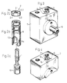
- Fig. 2a-2c is an exploded perspective view of the setting device of Fig. 1 with the associated indicator member.
- Fig. 3 shows a first embodiment of the invention in a cylinder end plate.
- Fig. 4 shows a second embodiment of the invention in a cylinder end plate.
- Fig. 1 thus shows an indicator device according to the invention in connection with a cylinder end plate 7.
- An indicator member comprising an indicator ring 2 is placed onto the outer part of a set screw 1.
- the indicator ring 2 On its outward surface (not shown) which is directed away from the cylinder end plate, the indicator ring 2 is provided with indicator markings e.g. in form of numerals (2.1 - 2.5, in Fig. 2a), which are readable against a reading mark in the form of a preferably fixed index (6 in Fig. 3), e.g. on the cylinder end plate surface, thereby indicating the rotational position of the set screw.
- a stepped reading ramp 5 is placed onto the cylinder end plate surface radially immediately outside the indicator ring 2. The hight of the steps corresponds to the pitch of the set screw, whereby an indication of the rotational, position of the set screw for an optional number of turns may be obtained by sighting or sensing with a finger.
- Fig. 1 The piston cylinder aggregate snown in Fig. 1 is a pneumatic cylinder with speed regulation and stroke end cushioning.
- This device which corresponds to the preamble of claim 1 is the subject of the applicant's own application SE-A-467424.
- the set screw 1 affects a valve body 12, which cooperates with two throttle openings 13, 14 of which the one 13 is arranged in a particular stroke end cushioning channel 21 and the other 14 in the outlet channel 22.
- Fig. 2a - 2c show the indicator ring 2 in connection with the setting device in an exploaded perspective view, from which it is clear that the throttle openings 13, 14 are essentially rectangular. With this shape a linear relation is obtained between the piston speed and the axial displacement of the valve body 12 and thus the rotational displacement of the set screw 1.
- Adjustment for achieving a distinct initial position, here zero position is obtained as follows:
- the set screw 1 is screwed into its sleeve 9, until the valve body 12 contacts a stop collar 17, being fixed in the lower part of the sleeve 9.
- the flow through the throttle openings is now completely closed, and the speed of the piston 11 is zero.
- the indicator ring 2 is now placed onto the outer part of the set screw, while assuring that the numeral zero appears right in front of the reading index.
- the indicator ring 2 is fixed, e.g. by tightening a locking screw in a threaded hole adapted for that purpose, in a per se known manner, or by letting an applied glue harden.
- Fig. 3 shows a device similar to the one in Fig. 1 whith an indicator member which also in this case comprises an indicator ring 2 being fixed onto the outer part of a set screw 1, in connection with a cylinder end plate 7, in which a valve body 12 being fixedly connected to the set screw 1 is indicated with dashed lines.
- the indicator ring 2 On its outward surface the indicator ring 2 is provided with indicator numerals (2.1 - 2.5 in Fig. 2a) from 0 to 4. These numerals here correspond to the speeds 0; 0.1; 0.2; 0.3; 0.4; m/s.
- the relation between the piston speed and the displacement of a setting device is obtained by simple testing of suitable throttle opening areas. When the relation is linear as above, the indicator numerals are evenly rotationally distributed on the indicator ring.
- the lines 2.1 - 2.5 are read against the index from the side as well as straight from above.
- the scale has been completed with a stepped reading ramp 5, which in this case comprises three steps with grades 0.5; 1.0; 1.5 m/s. This value is added to the value of the ring to obtain a true indication of the speed.
- Fig. 4 shows a second embodiment of the invention in connection with a cylinder end plate 7.
- the indicator member comprises an indicator ring 2 with indicator numerals from 0 - 4 on its outward surface, which are read against an index in the same manner as has been described above.
- the indicator ring 2 is further provided with a desired number of annular grooves or similar markings 16 distributed over its axial length, mutually spaced apart a distance corresponding to the pitch of the set screw.
- the indicator ring 2 In the initial position, when the speed of the piston is zero, the setting device is screwed into its inner position, the indicator ring 2 at least with its main part being located within a cylindric recess 15 in the cylinder end plate.
- the indicator ring 2 When the set screw 1 is then screwed out to partly open the throttle openings of the setting device, the indicator ring 2 will also be displaced axially outwards, whereby the annular grooves 16 or the like markings, will appear in correspondence to one, two or more screw turns out of the recess 15. Reading is simply achieved by sighting against an index applied beside the ring or along the wall of the cylinder end plate or the valve housing.
- the adjustment to obtain a distinct initial position may, if desired, be simply completed with axial adjustment in connection with the rotational adjustment.
- the setting device may thus be used in other kinds of piston cylinder aggregates than the shown and does not need to be contained in a cylinder end plate. Nor does the setting device need to comprise a valve body of the kind described in connection with the figures. Also other valve designs may come into question, e.g. needle valves.
- the indicator member does not necessarily have to be comprised of an indicator ring with outward indicator markings but may e.g. be comprised of a pointer cooperating with reading marks in the form of a fixed scale. This may be suitable particularly if the valve is a so called tap valve.
- the indicator member 2 may be manufactured from a suitable material, e.g. a synthetic material or metal and may be fixed to the set screw in a suitable manner, e.g. by a locking screw radially or axially, by glueing, soldering, stamping, shrinking, jolting or in any other way.
- the reading mark(s) may be integral with the reading ramp, which further does not have to bee stepped but may run continuously and possibly with a reading scale applied close to the indicator member.
- the indicator member may be integral with the set screw, the adjustment being achieved by applying/displacing the reading index for calibration against "the zero" of the indicator member.
- the indicator member may be comprised of a point, a line or the like on the set screw and the reading marks of a scale which is in principle shaped as the indicator ring in Fig. 4a and which is adjustable and then fixable close to the setting device.
- the reading index may be applied onto the valve housing or the cylinder end plate by casting, punching, painting, stamping or by applying a body by glueing, screwing, soldering or in any other way. In case the reading index as well as the stepped reading ramp are fixed, these members may be made integral with the cylinder end plate/valve housing.
- Both of the members may also be adjusted simultaneously, e.g. one axially and the other rotationally.
Landscapes
- Engineering & Computer Science (AREA)
- Physics & Mathematics (AREA)
- Fluid Mechanics (AREA)
- Mechanical Engineering (AREA)
- General Engineering & Computer Science (AREA)
- Indication Of The Valve Opening Or Closing Status (AREA)
- Pistons, Piston Rings, And Cylinders (AREA)
- Coating Apparatus (AREA)
- Actuator (AREA)
Claims (9)
- Vorrichtung zum Einstellen eines Bewegungsparameters für einen Kolben (11) in einer Kolben-Zylinder-Gruppe mit einer Einstelleinrichtung zur Fluidflußregulierung, die durch eine Einstellschraube (1) betätigt wird, wobei die Einstelleinrichtung zwei Elemente aufweist, nämlich wenigstens eine Ablesemarke (6) und einen Anzeigekörper (2), der gegen die Ablesemarke oder die Marken (6) lesbar ist, wobei eines der Elemente an der Einstelleinrichtung angebracht und damit beweglich ist und das andere Element nahe bei der Einstelleinrichtung stationär angeordnet ist, dadurch gekennzeichnet, daß die zwei Elemente unabhängig von der Position der Einstelleinrichtung derart zueinander verstellbar sind, daß eine genaue Ausgangsposition für die Einstellung erhalten wird, die nach der Verstellung fixierbar ist.
- Vorrichtung nach Anspruch 1, bei der die Einstellschraube (1) mit wenigstens einem Ventilkörper (12) verbunden ist, der im Zusammenwirken mit wenigstens einer Drosselöffnung (13, 14) das Ausströmen von Druckfluid aus der Kolben-Zylinder-Gruppe drosselt, dadurch gekennzeichnet, daß die Drosselöffnung oder die Öffnungen (13, 14) im wesentlichen rechteckig sind, um eine im wesentlichen lineare Beziehung zwischen der Verschiebung des Ventilkörpers (12) und der Geschwindigkeit des Kolbens (11) zu erhalten.
- Vorrichtung nach Anspruch 1 oder 2, dadurch gekennzeichnet, daß das Anzeigeelement (2) aus einem Anzeigering mit Anzeigemarkierungen besteht und die Ablesemarke aus einem Index (6) besteht.
- Vorrichtung nach Anspruch 3, dadurch gekennzeichnet, daß die Anzeigemarkierungen an der Außenfläche des Anzeigerings (2) angebracht sind und aus in Drehrichtung verteilten Anzeigeziffern (2.1-2.5) bestehen.
- Vorrichtung nach einem der Ansprüche 1 - 4, dadurch gekennzeichnet, daß die Ablesemarke aus einer abgestuften Ableserampe besteht, die radial unmittelbar außerhalb des Anzeigeelements (2) angeordnet ist, wobei die Schritthöhe der Ganghöhe der Einstellschraube (1) entspricht und die axiale Verschiebug der Einstellschraube gegen die Ableserampe lesbar ist.
- Vorrichtung nach Anspruch 3 oder 4, dadurch gekennzeichnet, daß der Anzeigering (2) Nuten oder Markierungen (16)) um seine einhüllende Fläche aufeist, wobei der Abstand zwischen zwei nebeneinanderliegenden Nuten oder Markierungen (16) der Ganghöhe der Einstellschraube (1) entspricht und die axiale Verschiebung der Einstellschraube durch die Nuten oder Markierungen (16) angegeben ist, die gegen einen neben dem Ring (2) oder einer Wand der Zylinderendplatte (7) oder des Ventilgehäuses angebrachten Index zu lesen sind.
- Vorrichtung nach einem der Ansprüche 1-6,
dadurch gekennzeichnet, daß das Anzeigeelement (2) in Drehrichtung und/oder axial verstellbar und danach an der Einstelleinrichtung fixierbar ist. - Vorrichtung nach einem der Ansprüche 1-7,
dadurch gekennzeichnet, daß die Ablesemarke(n) (6) in Drehrichtung und/cder axial verstellbar und danach nahe an der Einstelleinrichtung fixierbar ist/sind. - Vorrichtung nach einem der Ansprüche 1-8,
dadurch gekennzeichnet, daß die Befestigung nach dem Verstellen durch Kleben, Verschrauben, Löten, Stauchen, Kaltschlagen, Schrumpfen oder auf jede andere geeignete Weise erreicht wird.
Applications Claiming Priority (3)
| Application Number | Priority Date | Filing Date | Title |
|---|---|---|---|
| SE9100511A SE468176B (sv) | 1991-02-20 | 1991-02-20 | Anordning foer instaellning vid tryckmedieanordningar |
| SE9100511 | 1991-02-20 | ||
| PCT/SE1991/000898 WO1992014934A1 (en) | 1991-02-20 | 1991-12-20 | Adjusting means for fluid pressure devices |
Publications (2)
| Publication Number | Publication Date |
|---|---|
| EP0670968A1 EP0670968A1 (de) | 1995-09-13 |
| EP0670968B1 true EP0670968B1 (de) | 1998-06-10 |
Family
ID=20381952
Family Applications (1)
| Application Number | Title | Priority Date | Filing Date |
|---|---|---|---|
| EP92904126A Expired - Lifetime EP0670968B1 (de) | 1991-02-20 | 1991-12-20 | Einstelleinrichtung für druckflüssigkeitssystem |
Country Status (5)
| Country | Link |
|---|---|
| EP (1) | EP0670968B1 (de) |
| AU (1) | AU9174491A (de) |
| DE (1) | DE69129599T2 (de) |
| SE (1) | SE468176B (de) |
| WO (1) | WO1992014934A1 (de) |
Families Citing this family (2)
| Publication number | Priority date | Publication date | Assignee | Title |
|---|---|---|---|---|
| DE19928748A1 (de) * | 1999-03-26 | 2000-09-28 | Continental Teves Ag & Co Ohg | Elektromagnetventil, insbesondere für hydraulische Bremsanlagen mit Schlupfregelung |
| DE202004011993U1 (de) * | 2004-07-30 | 2005-12-08 | Liebherr-Werk Nenzing Ges.M.B.H. | Kolben-/Zylindereinheit |
Family Cites Families (5)
| Publication number | Priority date | Publication date | Assignee | Title |
|---|---|---|---|---|
| US604253A (en) * | 1898-05-17 | Engine-controlling device | ||
| DE1054845B (de) * | 1954-09-10 | 1959-04-09 | Christoph Willi Gehring | Vorrichtung zur hydraulischen Programmsteuerung |
| US3122063A (en) * | 1962-02-26 | 1964-02-25 | Arrow Tools Inc | Cylinder with improved sealing and governor means |
| US3442178A (en) * | 1967-08-21 | 1969-05-06 | Herbert H Peters | Hydraulically actuated stop for a hydraulic ram unit |
| US3559535A (en) * | 1969-01-21 | 1971-02-02 | Patrick W Conolly | Hydraulic cylinder with cushioned stroke |
-
1991
- 1991-02-20 SE SE9100511A patent/SE468176B/sv not_active IP Right Cessation
- 1991-12-20 EP EP92904126A patent/EP0670968B1/de not_active Expired - Lifetime
- 1991-12-20 WO PCT/SE1991/000898 patent/WO1992014934A1/en not_active Ceased
- 1991-12-20 AU AU91744/91A patent/AU9174491A/en not_active Abandoned
- 1991-12-20 DE DE69129599T patent/DE69129599T2/de not_active Expired - Fee Related
Also Published As
| Publication number | Publication date |
|---|---|
| DE69129599D1 (de) | 1998-07-16 |
| SE9100511L (sv) | 1992-08-21 |
| SE468176B (sv) | 1992-11-16 |
| SE9100511D0 (sv) | 1991-02-20 |
| AU9174491A (en) | 1992-09-15 |
| EP0670968A1 (de) | 1995-09-13 |
| WO1992014934A1 (en) | 1992-09-03 |
| DE69129599T2 (de) | 1998-11-26 |
Similar Documents
| Publication | Publication Date | Title |
|---|---|---|
| US6220588B1 (en) | Toggle clamping device or piston cylinder unit | |
| US4298101A (en) | Shock absorber | |
| US4313590A (en) | Solenoid valve for controlling flow of fluid | |
| US2642670A (en) | Gauge | |
| US5307729A (en) | Device for stroke end cushioning and speed regulating the movement of a piston in a fluid pressure cylinder | |
| EP0737286B1 (de) | Thermostat kopfteil eines heizkörperventils | |
| US4991310A (en) | Brake chamber stroke indicator | |
| EP0652854B1 (de) | Wegaufnehmer für den positionsnachweis eines pressstempels | |
| KR900017724A (ko) | 스핀들 장치 | |
| US6012903A (en) | Positive-displacement liquid-metering pump with continuously variable output | |
| EP0044287B1 (de) | Druckmittelbetriebener Stellzylinder mit einer Einrichtung zur Anzeige der Kolbenstellung in oder nahe der Endstellung | |
| EP0670968A1 (de) | Einstelleinrichtung für druckflüssigkeitssystem | |
| EP0889190A2 (de) | Steuereinrichtung für Türschliesser | |
| GB2161404A (en) | Pressurized clamp for securing tools or workpieces | |
| DE69715812D1 (de) | Kieferorthopädische Dehnschraube | |
| US2999512A (en) | Flow control valve | |
| GB2289115A (en) | Hydraulic force-applying device with thrust indicator | |
| FR2450156A1 (fr) | Dispositif de reglage pour groupe d'injection de machine a mouler les matieres synthetiques | |
| EP0169560B1 (de) | Kupplungs-Hauptzylinder | |
| US2826820A (en) | Hole gauges | |
| US5626071A (en) | Hydraulic ram with adjustable stop | |
| US4699044A (en) | Fluid cylinder device with precision stroke adjustment | |
| GB2240394A (en) | Pressure gauge with adjusting means | |
| US3364799A (en) | Offset boring head | |
| JPS5918167Y2 (ja) | 油圧シリンダ−のストロ−ク調節装置 |
Legal Events
| Date | Code | Title | Description |
|---|---|---|---|
| PUAI | Public reference made under article 153(3) epc to a published international application that has entered the european phase |
Free format text: ORIGINAL CODE: 0009012 |
|
| 17P | Request for examination filed |
Effective date: 19930830 |
|
| AK | Designated contracting states |
Kind code of ref document: A1 Designated state(s): DE FR GB |
|
| 17Q | First examination report despatched |
Effective date: 19961212 |
|
| GRAG | Despatch of communication of intention to grant |
Free format text: ORIGINAL CODE: EPIDOS AGRA |
|
| GRAG | Despatch of communication of intention to grant |
Free format text: ORIGINAL CODE: EPIDOS AGRA |
|
| GRAH | Despatch of communication of intention to grant a patent |
Free format text: ORIGINAL CODE: EPIDOS IGRA |
|
| GRAH | Despatch of communication of intention to grant a patent |
Free format text: ORIGINAL CODE: EPIDOS IGRA |
|
| GRAA | (expected) grant |
Free format text: ORIGINAL CODE: 0009210 |
|
| AK | Designated contracting states |
Kind code of ref document: B1 Designated state(s): DE FR GB |
|
| REF | Corresponds to: |
Ref document number: 69129599 Country of ref document: DE Date of ref document: 19980716 |
|
| ET | Fr: translation filed | ||
| PLBE | No opposition filed within time limit |
Free format text: ORIGINAL CODE: 0009261 |
|
| STAA | Information on the status of an ep patent application or granted ep patent |
Free format text: STATUS: NO OPPOSITION FILED WITHIN TIME LIMIT |
|
| 26N | No opposition filed | ||
| REG | Reference to a national code |
Ref country code: GB Ref legal event code: IF02 |
|
| PGFP | Annual fee paid to national office [announced via postgrant information from national office to epo] |
Ref country code: GB Payment date: 20031126 Year of fee payment: 13 |
|
| PGFP | Annual fee paid to national office [announced via postgrant information from national office to epo] |
Ref country code: DE Payment date: 20031205 Year of fee payment: 13 |
|
| PGFP | Annual fee paid to national office [announced via postgrant information from national office to epo] |
Ref country code: FR Payment date: 20031209 Year of fee payment: 13 |
|
| PG25 | Lapsed in a contracting state [announced via postgrant information from national office to epo] |
Ref country code: GB Free format text: LAPSE BECAUSE OF NON-PAYMENT OF DUE FEES Effective date: 20041220 |
|
| PG25 | Lapsed in a contracting state [announced via postgrant information from national office to epo] |
Ref country code: DE Free format text: LAPSE BECAUSE OF NON-PAYMENT OF DUE FEES Effective date: 20050701 |
|
| GBPC | Gb: european patent ceased through non-payment of renewal fee |
Effective date: 20041220 |
|
| PG25 | Lapsed in a contracting state [announced via postgrant information from national office to epo] |
Ref country code: FR Free format text: LAPSE BECAUSE OF NON-PAYMENT OF DUE FEES Effective date: 20050831 |
|
| REG | Reference to a national code |
Ref country code: FR Ref legal event code: ST |