EP0670957B1 - Erdgas-expansionsanlage - Google Patents
Erdgas-expansionsanlage Download PDFInfo
- Publication number
- EP0670957B1 EP0670957B1 EP94901812A EP94901812A EP0670957B1 EP 0670957 B1 EP0670957 B1 EP 0670957B1 EP 94901812 A EP94901812 A EP 94901812A EP 94901812 A EP94901812 A EP 94901812A EP 0670957 B1 EP0670957 B1 EP 0670957B1
- Authority
- EP
- European Patent Office
- Prior art keywords
- natural gas
- generator
- heat exchanger
- heat
- gas
- Prior art date
- Legal status (The legal status is an assumption and is not a legal conclusion. Google has not performed a legal analysis and makes no representation as to the accuracy of the status listed.)
- Expired - Lifetime
Links
- VNWKTOKETHGBQD-UHFFFAOYSA-N methane Chemical compound C VNWKTOKETHGBQD-UHFFFAOYSA-N 0.000 title claims abstract description 84
- 239000003345 natural gas Substances 0.000 title claims abstract description 42
- 238000011144 upstream manufacturing Methods 0.000 claims abstract description 3
- 239000002918 waste heat Substances 0.000 claims description 9
- 238000010438 heat treatment Methods 0.000 claims description 5
- 238000001816 cooling Methods 0.000 claims description 4
- XLYOFNOQVPJJNP-UHFFFAOYSA-N water Substances O XLYOFNOQVPJJNP-UHFFFAOYSA-N 0.000 claims description 4
- 239000007789 gas Substances 0.000 abstract description 22
- 238000002485 combustion reaction Methods 0.000 abstract description 5
- 230000005611 electricity Effects 0.000 description 8
- 239000000498 cooling water Substances 0.000 description 4
- MWUXSHHQAYIFBG-UHFFFAOYSA-N Nitric oxide Chemical compound O=[N] MWUXSHHQAYIFBG-UHFFFAOYSA-N 0.000 description 3
- 230000003197 catalytic effect Effects 0.000 description 2
- 238000010586 diagram Methods 0.000 description 2
- 239000000314 lubricant Substances 0.000 description 2
- 239000003921 oil Substances 0.000 description 2
- 238000005299 abrasion Methods 0.000 description 1
- 230000005540 biological transmission Effects 0.000 description 1
- 230000015572 biosynthetic process Effects 0.000 description 1
- 239000006227 byproduct Substances 0.000 description 1
- 230000003749 cleanliness Effects 0.000 description 1
- 230000003750 conditioning effect Effects 0.000 description 1
- 239000000112 cooling gas Substances 0.000 description 1
- 238000006073 displacement reaction Methods 0.000 description 1
- 239000000446 fuel Substances 0.000 description 1
- 239000010687 lubricating oil Substances 0.000 description 1
- 238000005461 lubrication Methods 0.000 description 1
- 230000007246 mechanism Effects 0.000 description 1
- 238000000034 method Methods 0.000 description 1
- 239000000203 mixture Substances 0.000 description 1
- 238000010248 power generation Methods 0.000 description 1
- 230000008569 process Effects 0.000 description 1
- 238000005096 rolling process Methods 0.000 description 1
- 239000000725 suspension Substances 0.000 description 1
- 230000001360 synchronised effect Effects 0.000 description 1
- 230000009466 transformation Effects 0.000 description 1
- 230000007704 transition Effects 0.000 description 1
- 230000032258 transport Effects 0.000 description 1
- 238000004804 winding Methods 0.000 description 1
Images
Classifications
-
- F—MECHANICAL ENGINEERING; LIGHTING; HEATING; WEAPONS; BLASTING
- F02—COMBUSTION ENGINES; HOT-GAS OR COMBUSTION-PRODUCT ENGINE PLANTS
- F02C—GAS-TURBINE PLANTS; AIR INTAKES FOR JET-PROPULSION PLANTS; CONTROLLING FUEL SUPPLY IN AIR-BREATHING JET-PROPULSION PLANTS
- F02C1/00—Gas-turbine plants characterised by the use of hot gases or unheated pressurised gases, as the working fluid
-
- F—MECHANICAL ENGINEERING; LIGHTING; HEATING; WEAPONS; BLASTING
- F02—COMBUSTION ENGINES; HOT-GAS OR COMBUSTION-PRODUCT ENGINE PLANTS
- F02C—GAS-TURBINE PLANTS; AIR INTAKES FOR JET-PROPULSION PLANTS; CONTROLLING FUEL SUPPLY IN AIR-BREATHING JET-PROPULSION PLANTS
- F02C1/00—Gas-turbine plants characterised by the use of hot gases or unheated pressurised gases, as the working fluid
- F02C1/04—Gas-turbine plants characterised by the use of hot gases or unheated pressurised gases, as the working fluid the working fluid being heated indirectly
-
- F—MECHANICAL ENGINEERING; LIGHTING; HEATING; WEAPONS; BLASTING
- F17—STORING OR DISTRIBUTING GASES OR LIQUIDS
- F17D—PIPE-LINE SYSTEMS; PIPE-LINES
- F17D1/00—Pipe-line systems
- F17D1/02—Pipe-line systems for gases or vapours
- F17D1/065—Arrangements for producing propulsion of gases or vapours
- F17D1/075—Arrangements for producing propulsion of gases or vapours by mere expansion from an initial pressure level, e.g. by arrangement of a flow-control valve
Definitions
- the invention relates to a natural gas expansion system for expanding natural gas, which is supplied under high pressure and is to be fed at a lower pressure into a distribution network leading to the end users.
- natural gas In gas pipelines, natural gas is at a relatively high pressure of around 55 bar, while in the consumer network there is a lower pressure of 9 bar, for example.
- natural gas expansion systems are required in which the pressure is reduced. When the pressure is reduced, energy is released that can be used to generate electricity.
- piston expansion machines in natural gas expansion plants, which are called volumetric Displacement machines work, and thus drive a generator.
- Expansion systems are also known which work with expansion turbines. Oil is used as bearing lubrication in these systems. Since the natural gas cools down during expansion, the natural gas is heated to the extent that the cooling does not take place below the critical range of 0 ° C. This requirement makes the system insensitive to moisture in natural gas. Thermal energy must be provided for heating. This heat is normally generated using boiler systems.
- a gas expansion plant which has a power plant which consists of an engine and a power generator.
- the engine's waste heat is fed to a heat exchanger, which preheats the gas flowing to an expansion turbine.
- the amount of heat given off to the gas cannot be changed without giving up the engine at full load.
- the invention has for its object to provide a natural gas expansion system that works regardless of the current need for relaxed natural gas constantly with high efficiency or good energy efficiency.
- the energy supplied to the heat exchanger connected upstream of the turbogenerator is applied by at least one combined heat and power plant Has gas internal combustion engine and a generator for power generation.
- the waste heat from the combined heat and power plant which is operated at full load, is used to preheat the natural gas.
- a cogeneration plant has the greatest efficiency in full load operation, while the efficiency is significantly reduced at partial load.
- the combined heat and power plant is either operated at full load or switched off, depending on the requirements of the natural gas network. So it will always worked with high efficiency, whereby the generator of the combined heat and power plant generates electrical energy that can be fed into the electricity network.
- the combined heat and power plants On cold winter days, when the demand for natural gas is high, the combined heat and power plants also generate a lot of electricity, which helps to cover the increased electricity demand.
- the heat that is supplied to the natural gas before it expands is generated by limited, relatively small units, namely the combined heat and power plants, which also emit part of the energy supplied to them in the form of electrical current.
- This generation of electricity falls off to a certain extent as a by-product, but is desirable because it occurs when the demand for electricity is particularly high.
- the temperature of the natural gas is preferably increased by the heat exchangers to a temperature below 100 ° C. in order to use gas engines in the combined heat and power plants that work with cooling water below 100 ° C.
- the enthalpy-entropy diagram for natural gas shows that with such low preheating temperatures only pressure ratios up to approx. 2 - 3.5 can be reduced in one step with very good efficiency. If the existing pressure drop exceeds these conditions, if the efficiency is good, significantly higher preheating temperatures are required.
- a relaxation machine which can reduce pressure ratios by 3 in one step with excellent efficiency, is the centripetal turbine with radial flow, used in the invention, a kind of Francis turbine for compressible media. Volume flow and power are controlled via adjustable guide vanes. Due to the guide vane mechanism, this turbine also has an outstanding efficiency in the partial load range, in contrast to many other turbines.
- a radially high turbine wheel is attached directly to the free shaft end of a flameproof, magnetically-supported medium-frequency generator.
- the magnetic bearing generator works without any lubricants in the bearings. Pollution of the natural gas by oil is therefore not possible at all.
- the losses in the magnetic bearings are at least a power of ten lower than in the known oil-lubricated bearings.
- the flameproof housing ensures that no natural gas can escape from the generator-turbine unit.
- the waste heat generated in the generator package is cooled away by a water circuit and can be added to the relaxation process via heat exchangers.
- the medium-frequency current (depending on the generator type up to approx. 1100 Hz) is first rectified in a converter matched to the generator and then fed into the public 3 x 400 V, 50 Hz network via an inverter.
- the inverters are designed so that the harmonic content the network-side currents meet the requirements of the energy supply companies. For larger outputs, the energy can be fed into the medium-voltage network via a corresponding transformer (e.g. 10 kV).
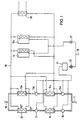
- the natural gas expansion system shown in Fig. 1 is supplied with natural gas through a high pressure line 10 in which the pressure e.g. Is 55 bar at a temperature of 5 to 10 ° C.
- the low-pressure line 11 leading out of the expansion system is connected to the natural gas supply network, in which there is a pressure of approximately 9 bar at a temperature of 5 to 10 ° C.
- the natural gas flows from the high-pressure line 10 through a heat exchanger 12, in which it is heated to a temperature below 100 ° C., for example to 70 ° C., and then through a turbogenerator 13, in which the pressure is released to about 22 bar.
- the turbo generator 13 a further heat exchanger 14 and a further turbo generator 15 are connected downstream.
- the outlet of the turbogenerator 15 is connected to the low pressure line 11.
- the series connection of the heat exchanger 12, the turbogenerator 13, the heat exchanger 14 and the turbogenerator 15 can be connected in parallel to a series connection of the same components, the letter "a" being added in each case. These two parallel branches are connected between the high pressure line 10 and the low pressure line 11.
- the heat exchangers 12, 12a and 14, 14a are supplied with thermal energy from a parallel circuit comprising a plurality of combined heat and power plants 16, 16a. All heat exchangers 12, 12a, 14, 14a are connected directly to the parallel connection of the combined heat and power plants, so that all heat exchangers form a parallel connection.
- the combined heat and power plants form with all heat exchangers a closed heat transfer circuit 19, in which e.g. Water circulates as a heat transfer medium.
- Each combined heat and power plant consists of a gas engine, which is operated with the natural gas taken from the low-pressure line 11, and a generator driven by the gas engine, which generates electricity.
- the output lines of the generators are transformed to the mains voltage via a transformer station 17 and then fed into the electrical supply network 18.
- the gas motors drive the generators at such a controlled speed that the AC voltage is generated at the network frequency and in phase with the supply network.
- Combined heat and power units with lean combustion are used to preheat the natural gas.
- the lean burn reduces nitrogen oxide formation through internal engine measures right during the combustion. Exhaust gas cleanliness can be brought close to the values of systems with 3-way catalytic converters without the help of catalytic converters.
- the engine control electronics set certain gas conditioning and combustion conditions that are stable in continuous operation. The efficiencies include noticeably higher due to mixture charging.
- the waste heat from the combined heat and power plants 16, 16a which is absorbed by the circuit 19 containing the heat exchangers 12, 12a, 14, 14a, is used in part to heat the natural gas.
- a further heat exchanger 20 is connected to the circuit 19 and is coupled to an external energy consumer or generator, for example to the return line of a district heating network. In this way, heat generated by the combined heat and power plants and by the heat exchangers 12, 12a, 14, 14a was not discharged, fed into the district heating network or fed to another consumer.
- the current generated by the turbogenerators 13, 13a, 15, 15a is fed to a frequency converter 21, where it is brought to the mains frequency.
- a transformation to the level of the line voltage then takes place in a transformer 22 before the current is fed into the supply network 18. Electricity is thus generated both in the generation of heat in the combined heat and power plants and in the expansion in the turbogenerators, which is fed into the supply network.
- the circuit 19 absorbs the waste heat from the combined heat and power plants 16, 16a, i.e. the exhaust gas heat and the waste heat, and transports them to the respective heat exchangers.
- the heat transfer medium water has e.g. a flow temperature of slightly below 100 ° C, so that the temperature in the heat exchangers is about 90 ° C, whereby the natural gas is heated to about 70 ° C.
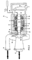
- Fig. 2 shows schematically the structure of the turbogenerator 13 in which the expansion of the natural gas takes place.
- the other turbo generators are designed in the same way.
- the turbogenerator 13 has an expansion turbine 25 with a radial inlet 26 and an axial outlet 27.
- the turbine wheel 28 is rotatably supported, and the natural gas, which is under high pressure (55 bar), flows radially against it, causing it to rotate.
- the turbine wheel 28 is fastened to a shaft 29 which is supported in the generator housing 30 is.
- the generator housing 30 directly adjoins the turbine housing and the shaft 29 protrudes from the generator housing 30 into the turbine housing.
- the generator housing 30 is completely encapsulated with the exception of the shaft bushing leading into the turbine housing, ie the shaft 29 is led out of the generator housing 30 only towards the turbine housing.
- the shaft 29 is mounted in magnetic bearings 31, 32, 33, the magnetic bearings 31 and 32 radial bearings and the magnetic bearing 33 being an axial bearing.
- the magnetic bearings hold the rotating shaft 29 magnetically in suspension, so that the shaft is supported without contact.
- catch bearings are provided which support the shaft 29 in the case of non-excited magnetic bearings.
- the position of the shaft 29 is monitored by sensors (not shown) which are arranged in a ring. There is a separate ring-shaped sensor for each magnetic bearing. The signals from the sensors are processed in separate control loops to control the magnetic bearings.
- Permanent magnets 34 which form the rotor of the synchronous generator, are fastened to the shaft 29 of the rotor.
- the stator consists of laminated electrical sheets and generator windings 35 fastened in the housing 30, which are connected via cables 36 to the frequency converter 21 (FIG. 1).
- the stator is cooled by cooling channels 37 through which cooling water flows.
- the interior of the housing 30 is cooled here with gas which is removed from the turbine housing via the leakage gap of the shaft 29. Additionally or alternatively, external cooling gas can be introduced into the housing 30 through a gas inlet 38. The gas flows through the ring gaps the axial bearing 31 and 33 and along the rotor and is discharged at the opposite end of the housing through a cooling outlet 39.
- the turbogenerator 13 Since there are no moving parts in the housing 30 that have friction with other components, no abrasion is generated, so that no foreign matter can penetrate into the turbine housing.
- the turbogenerator 13 is designed to be pressure-tight, so that even in the event of a secondary quick-close (at outlet 27), no natural gas escapes into the atmosphere.
- the bearing of the shaft 29 is lubricant-free.
- the power loss of the turbogenerator essentially consists of the gas friction losses and the ohmic losses as well as the eddy current losses. The heat loss is returned to the natural gas.
Landscapes
- Engineering & Computer Science (AREA)
- Chemical & Material Sciences (AREA)
- Combustion & Propulsion (AREA)
- Mechanical Engineering (AREA)
- General Engineering & Computer Science (AREA)
- Engine Equipment That Uses Special Cycles (AREA)
- Control Of Eletrric Generators (AREA)
- Fertilizers (AREA)
- Pretreatment Of Seeds And Plants (AREA)
- Catalysts (AREA)
- Carbon And Carbon Compounds (AREA)
Description
- Die Erfindung betrifft eine Erdgas-Expansionsanlage zum Entspannen von Erdgas, das unter hohem Druck geliefert wird und mit niedrigerem Druck in ein zu den Endverbrauchern führendes Verteilernetz eingespeist werden soll.
- In Fernleitungen steht Erdgas unter einem relativ hohen Druck von etwa 55 bar, während im Verbrauchernetz ein niedrigerer Druck von z.B. 9 bar herrscht. Am Übergang von dem Fernleitungsnetz zum Verteilernetz sind Erdgas-Expansionsanlagen erforderlich, in denen eine Druckreduzierung erfolgt. Bei der Druckreduzierung wird Energie frei, die zur Stromerzeugung genutzt werden kann. Es ist bekannt, in Erdgas-Expansionsanlagen Kolben-Expansionsmaschinen einzusetzen, die als volumetrische Verdrängermaschinen arbeiten, und damit einen Generator zu treiben. Ferner sind auch Expansionsanlagen bekannt, die mit Expansionsturbinen arbeiten. Bei diesen Anlagen wird Öl als Lagerschmierung eingesetzt. Da das Erdgas sich bei der Expansion abkühlt, erfolgt vor der Expansion eine Erwärmung des Erdgases in dem Maße, daß die Abkühlung nicht unter den kritischen Bereich von 0 °C erfolgt. Diese Forderung macht die Anlage gegenüber Feuchtigkeit im Erdgas unempfindlich. Für die Erwärmung muß Wärmeenergie bereitgestellt werden. Die Erzeugung dieser Wärme erfolgt normalerweise unter Verwendung von Heizkesselanlagen.
- Aus EP-A-0 004 398 ist eine Gasentspannungsanlage bekannt, die ein Kraftwerk aufweist, welches aus einem Motor und einem Stromgenerator besteht. Die Abwärme des Motors wird einem Wärmetauscher zugeführt, der das zu einer Entspannungsturbine strömende Gas vorwärmt. Hierbei kann die Wärmemenge, die an das Gas abgegeben wird, nicht verändert werden, ohne den Vollastbetrieb des Motors aufzugeben.
- Der Erfindung liegt die Aufgabe zugrunde, eine Erdgas-Expansionsanlage zu schaffen, die unabhängig von dem momentanen Bedarf an entspanntem Erdgas ständig mit hohem Wirkungsgrad bzw. guter Energieausnutzung arbeitet.
- Die Lösung dieser Aufgabe erfolgt erfindungsgemäß mit den im Anspruch 1 angegebenen Merkmalen.
- Nach der Erfindung wird die dem dem Turbogenerator vorgeschalteten Wärmetauscher zugeführte Energie von mindestens einem Blockheizkraftwerk aufgebracht, das einen Gas-Verbrennungsmotor und einen Generator zur Stromerzeugung aufweist. Für die Vorwärmung des Erdgases wird die Abwärme des Blockheizkraftwerks ausgenutzt, das im Vollastbetrieb gefahren wird. Ein Blockheizkraftwerk hat im Vollastbetrieb den größten Wirkungsgrad, während sich bei Teillast der Wirkungsgrad erheblich verringert. Nach der Erfindung wird das Blockheizkraftwerk entweder im Vollastbetrieb betrieben oder abgeschaltet, je nach Anforderung des Erdgasnetzes. Es wird also stets mit hohem Wirkungsgrad gearbeitet, wobei der Generator des Blockheizkraftwerks elektrische Energie erzeugt, die in das Elektrizitätsnetz eingespeist werden kann. An kalten Wintertagen, an denen der Bedarf an Erdgas groß ist, erzeugen die Blockheizkraftwerke, ebenfalls viel Strom, was zur Deckung des dann auch erhöhten Strombedarfs beiträgt.
- Nach der Erfindung wird die Wärme, die dem Erdgas vor seiner Expansion zugeführt wird, durch jeweils begrenzte relativ kleine Einheiten, nämlich die Blockheizkraftwerke, erzeugt, die darüber hinaus einen Teil der ihnen zugeführten Energie in Form elektrischen Stromes abgeben. Diese Stromerzeugung fällt gewissermaßen als Nebenprodukt ab, ist aber erwünscht, weil sie dann anfällt, wenn der Strombedarf besonders groß ist.
- Vorzugsweise erfolgt die Temperaturerhöhung des Erdgases durch die Wärmetauscher auf eine Temperatur unter 100 °C, um in den Blockheizkraftwerken Gasmotoren zu verwenden, die mit Kühlwasser unter 100 °C arbeiten. Andererseits ergibt das Enthalpie-Entropie-Diagramm für Erdgas, daß bei so niedrigen Vorwärmtemperaturen nur Druckverhältnisse bis ca. 2 - 3,5 mit sehr gutem Wirkungsgrad einstufig abzubauen sind. Überschreitet das vorhandene Druckgefälle diese Verhältnisse, so sind, guten Wirkungsgrad vorausgesetzt, deutlich höhere Vorwärmtemperaturen erforderlich.
- Beschränkt man sich auf Vorwärmtemperaturen unter 100 °C, bietet sich eine mehrstufige Entspannung mit Zwischenerwärmung an.
- Eine Entspannungsmaschine, die einstufig mit hervorragendem Wirkungsgrad Druckverhältnisse um 3 abbauen kann, ist die in der Erfindung verwendete, radial angeströmte Zentripetalturbine, eine Art Francis-Turbine für kompressible Medien. Volumenstrom und Leistung werden über verstellbare Leitschaufeln kontrolliert. Durch den Leitschaufelmechanismus bedingt hat diese Turbine auch im Teillastbereich, im Gegensatz zu vielen anderen Turbinen, einen hervorragenden Wirkungsgrad.
- Ein radial hochanfallendes Turbinenrad ist direkt an dem freien Wellenende eines druckfest gekapselten, magnetgelagerten Mittelfrequenzgenerators befestigt.
- Der magnetgelagerte Generator arbeitet ohne jegliche Schmiermittel in den Lagern. Eine Verschmutzung des Erdgases durch Öl ist also überhaupt nicht möglich. Die Verluste in den Magnetlagern sind mindestens um eine Zehnerpotenz niedriger als bei den bekannten ölgeschmierten Lagern. Das druckfest gekapselte Gehäuse sorgt dafür, daß kein Erdgas aus der Generator-Turbineneinheit entweichen kann.
- Die im Generatorpaket anfallende Verlustwärme wird über einen Wasserkreislauf weggekühlt und kann dem Entspannungsprozeß über Wärmetauscher wieder hinzugefügt werden.
- Da der Generator mit der Turbinendrehzahl rotiert, ist eine direkte Einspeisung in das öffentliche Netz (50 Hz) nicht möglich. Der mittelfrequente Strom (je nach Generatortyp bis ca. 1100 Hz) wird in einem auf den Generator abgestimmten Umrichter zunächst gleichgerichtet und dann über einen Wechselrichter in das öffentliche 3 x 400 V, 50 Hz Netz eingespeist. Die Umrichter sind schaltungsgemäß so konzipiert, daß der Oberwellengehalt der netzseitigen Ströme den Anforderungen der Energieversorgungs-Unternehmen entspricht. Bei größeren Leistungen bietet sich die Einspeisung der Energie über einen entsprechenden Trafo in das Mittelspannungsnetz (z.B. 10 kV).
- Durch den Verzicht auf Gleitlager und Wälzlager sowie den Verzicht auf Wellendichtungen und Schmiermittel wird sichergestellt, daß keine Fremdstoffe in die Gasleitung eindringen und das Gas verunreinigen können.
- Im folgenden wird unter Bezugnahme auf die Zeichnungen ein Ausführungsbeispiel der Erfindung näher erläutert.
- Es zeigen:
- Fig. 1
- ein Blockschaltbild der Erdgas-Expansionsanlage und
- Fig. 2
- einen schematischen Schnitt durch einen der Turbogeneratoren.
- Der in Fig. 1 dargestellten Erdgas-Expansionsanlage wird das Erdgas durch eine Hochdruckleitung 10 zugeführt, in der der Druck z.B. 55 bar beträgt, bei einer Temperatur von 5 bis 10 °C. Die aus der Expansionsanlage herausführende Niederdruckleitung 11 ist an das Erdgas-Versorgungsnetz angeschlossen, in dem ein Druck von etwa 9 bar bei einer Temperatur von 5 bis 10 °C herrscht.
- Das Erdgas strömt von der Hochdruckleitung 10 durch einen Wärmetauscher 12, in dem es auf eine unter 100 °C liegende Temperatur erwärmt wird, z.B. auf 70 °C, und danach durch einen Turbogenerator 13, in dem eine Entspannung auf etwa 22 bar erfolgt. Dem Turbogenerator 13 sind ein weiterer Wärmetauscher 14 und ein weiterer Turbogenerator 15 nachgeschaltet. Der Auslaß des Turbogenerators 15 ist mit der Niederdruckleitung 11 verbunden.
- Die Reihenschaltung aus dem Wärmetauscher 12, dem Turbogenerator 13, dem Wärmetauscher 14 und dem Turbogenerator 15 kann einer Reihenschaltung aus den gleichen Komponenten parallelgeschaltet sein, wobei jeweils der Buchstabe "a" hinzugefügt ist. Diese beiden Parallelzweige sind zwischen die Hochdruckleitung 10 und die Niederdruckleitung 11 geschaltet.
- Die Wärmetauscher 12,12a und 14,14a werden von einer Parallelschaltung aus mehreren Blockheizkraftwerken 16,16a mit Wärmeenergie versorgt. Sämtliche Wärmetauscher 12,12a,14,14a sind unmittelbar an die Parallelschaltung der Blockheizkraftwerke angeschlossen, so daß sämtliche Wärmetauscher eine Parallelschaltung bilden. Die Blockheizkraftwerke bilden mit sämtlichen Wärmetauschern einen geschlossenen Wärmeübertragungskreislauf 19, in dem z.B. Wasser als Wärmeübertragungsmedium zirkuliert.
- Jedes Blockheizkraftwerk besteht aus einem Gasmotor, der mit dem der Niederdruckleitung 11 entnommenen Erdgas betrieben wird, und einem von dem Gasmotor angetriebenen Generator, der Strom erzeugt. Die Ausgangsleitungen der Generatoren werden über eine Transformatorenstation 17 auf die Netzspannung transformiert und dann in das elektrische Versorgungsnetz 18 eingespeist. Die Gasmotore treiben die Generatoren mit einer solchen geregelten Geschwindigkeit an, daß die Wechselspannung mit der Netzfrequenz und in Phase mit dem Versorgungsnetz erzeugt wird.
- Für die notwendige Vorheizung des Erdgases werden Blockheizkraftwerk-Motoren mit Magerverbrennung eingesetzt. Die Magerverbrennung vermindert die Stickoxidentstehung durch innermotorische Maßnahmen gleich bei der Verbrennung. Die Abgassauberkeit kann ohne Hilfe von Katalysatoren nahe an die Werte von Anlagen mit 3-Wege-Katalysatoren herangebracht werden. Die Motor-Regelungselektronik stellt bestimmte Gasaufbereitungs- und Verbrennungsbedingungen ein, die im Dauerbetrieb stabil sind. Die Wirkungsgrade sind u.a. durch Gemischaufladung merklich höher.
- Aus der eingesetzten Primärenergie Erdgas werden am Motor-Schwungrad 35,4 % mechanische Energie abgegeben. Der Generator wandelt die Antriebsenergie in 33,9 % elektrische Energie um, die ins örtliche Netz eingespeist wird. Die 61,7 % abzuführende Wärmeenergie aus dem Abgas, Motorkühlwasser und Schmieröl gelangt über Kühlwasser- und Abgaswärmeübertrager zu 57,3 % nutzbarer Wärmeenergie an die Heizungsanlage.
- 100 % Kraftstoff-Energie werden zu 33,9 % elektrischer und 57,3 % thermischer Energie umgewandelt. Dies ergibt den außerordentlich hohen Nutzungsgrad von 91,2 %. Lediglich 8,8 % sind Verluste.
- Die Abwärme der Blockheizkraftwerke 16,16a, die von dem die Wärmetauscher 12,12a,14,14a enthaltenden Kreislauf 19 aufgenommen wird, wird teilweise zur Aufheizung des Erdgases benutzt. An den Kreislauf 19 ist ein weiterer Wärmetauscher 20 angeschlossen, der mit einem externen Energieverbraucher oder Energieerzeuger gekoppelt ist, beispielsweise mit der Rücklaufleitung eines Fernwärmenetzes. Auf diese Weise kann Wärme, die von den Blockheizkraftwerken erzeugt worden ist und die von den Wärmetauschern 12,12a,14,14a nicht abgeführt wurde, in das Fernwärmenetz eingespeist oder einem anderen Verbraucher zugeführt werden.
- Der von den Turbogeneratoren 13,13a,15,15a erzeugte Strom wird einem Frequenzumrichter 21 zugeführt, wo er auf Netzfrequenz gebracht wird. Anschließend erfolgt in einem Transformator 22 eine Transformation auf die Höhe der Netzspannung, bevor der Strom in das Versorgungsnetz 18 eingespeist wird. Sowohl bei der Wärmeerzeugung in den Blockheizkraftwerken, als auch bei der Expansion in den Turbogeneratoren entsteht somit Strom, der dem Versorgungsnetz zugeführt wird.
- Der Kreislauf 19 nimmt die Abwärme der Blockheizkraftwerke 16,16a auf, d.h. die Abgaswärme und die Verlustwärme, und transportiert sie zu den jeweiligen Wärmetauschern. Das Wärmeübertragungsmedium (Wasser) hat z.B. eine Vorlauftemperatur von etwas unter 100 °C, so daß die Temperatur in den Wärmetauschern etwa 90 °C beträgt, wodurch das Erdgas auf jeweils etwa 70 °C aufgeheizt wird.
- Fig. 2 zeigt schematisch den Aufbau des Turbogenerators 13, in dem die Expansion des Erdgases erfolgt. Die übrigen Turbogeneratoren sind in gleicher Weise ausgebildet.
- Der Turbogenerator 13 weist eine Expansionsturbine 25 mit einem radialen Einlaß 26 und einem axialen Auslaß 27 auf. In der Turbine 25 ist das Turbinenrad 28 drehbar gelagert, das von dem unter hohem Druck (55 bar) stehenden Erdgas radial angeströmt und dadurch in Drehung versetzt wird. Das Turbinenrad 28 ist an einer Welle 29 befestigt, die in dem Generatorgehäuse 30 gelagert ist. Das Generatorgehäuse 30 schließt sich unmittelbar an das Turbinengehäuse an und die Welle 29 ragt aus dem Generatorgehäuse 30 in das Turbinengehäuse hinein. Das Generatorgehäuse 30 ist mit Ausnahme der in das Turbinengehäuse führenden Wellendurchführung vollständig gekapselt, d.h. die Welle 29 ist nur zum Turbinengehäuse hin aus dem Generatorgehäuse 30 herausgeführt. Die Welle 29 ist in Magnetlagern 31,32,33 gelagert, wobei die Magnetlager 31 und 32 Radiallager und das Magnetlager 33 ein Axiallager ist. Die Magnetlager halten die rotierende Welle 29 magnetisch in der Schwebe, so daß die Welle berührungsfrei gelagert ist. Ferner sind Fanglager vorgesehen, die bei nicht-erregten Magnetlagern die Welle 29 abstützen. Die Position der Welle 29 wird von (nicht dargestellten) Sensoren überwacht, die ringförmig angeordnet sind. Für jedes Magnetlager ist ein eigener ringförmiger Sensor vorhanden. Die Signale der Sensoren werden in separaten Regelkreisen verarbeitet, um die Magnetlager zu steuern.
- Auf der Welle 29 des Rotors sind Permanentmagnete 34 befestigt, die den Rotor des Synchrongenerators bilden. Der Stator besteht aus lamellierten Elektroblechen und im Gehäuse 30 befestigten Generatorwicklungen 35, die über Kabel 36 mit dem Frequenzumsetzer 21 (Fig. 1) verbunden sind. Die Kühlung des Stators erfolgt durch Kühlkanäle 37, die von Kühlwasser durchströmt sind.
- Das Innere des Gehäuses 30 wird hier mit Gas gekühlt, das über den Leckspalt der Welle 29 dem Turbinengehäuse entnommen wird. Zusätzlich oder alternativ kann durch einen Gaseinlaß 38 externes Kühlgas in das Gehäuse 30 eingeleitet werden. Das Gas strömt durch die Ringspalte der Axiallager 31 und 33 sowie am Rotor entlang und wird am entgegengesetzten Gehäuseende durch einen Kühlauslaß 39 abgeführt.
- Da in dem Gehäuse 30 keine bewegten Teil vorhanden sind, die Reibung mit anderen Komponenten haben, wird kein Abrieb erzeugt, so daß keine Fremdstoffartikel in das Turbinengehäuse eindringen können. Der Turbogenerator 13 ist druckdicht ausgeführt, so daß selbst im Falle eines sekundären Schnellschlusses (am Auslaß 27) kein Erdgas in die Atmosphäre entweicht. Die Lagerung der Welle 29 ist schmierstofffrei. Die Verlustleistung des Turbogenerators besteht im wesentlichen aus den Gasreibungsverlusten und den Ohmschen Verlusten sowie den Wirbelstromverlusten. Die Verlustwärme wird in das Erdgas zurückgeführt.
Claims (5)
- Erdgas-Expansionsanlage mit einem Wärmetauscher (12) zum Vorwärmen des unter hohem Druck stehenden Erdgases, einem Turbogenerator (13) zum Entspannen des Erdgases auf einen niedrigeren Druck und zur Stromerzeugung aus der dabei freiwerdenden Energie und mit einem Kraftwerk, das mit seiner Abwärme den Wärmetauscher (12) speist,
dadurch gekennzeichnet,
daß das Kraftwerk aus mehreren Blockheizkraftwerken (16,16a) mit jeweils einem Gas-Verbrennungsmotor und einem Generator besteht, die einzeln entweder ausgeschaltet oder mit Vollast im Digitalbetrieb betrieben sind, und daß der Abwärmekreislauf (19) der Blockheizkraftwerke (16,16a) thermisch mit einem externen Energieverbraucher oder Energieerzeuger gekoppelt ist, um die beim Digitalbetrieb der Blockheizkraftwerke ohne externe Kühlungsmaßnahmen anfallende Rest-Wärememenge abzuführen. - Erdgas-Expansionsanlage nach Anspruch 1, dadurch gekennzeichnet, daß die Erwärmung des Erdgases im Wärmetauscher (12) auf unter 100 °C erfolgt.
- Erdgas-Expansionsanlage nach Anspruch 1 oder 2, dadurch gekennzeichnet, daß zwei Turbogeneratoren (13,15) hintereinandergeschaltet sind und jedem dieser Turbogeneratoren ein Wärmetauscher (12,14) vorgeschaltet ist.
- Erdgas-Expansionsanlage nach einem der Ansprüche 1 bis 3, dadurch gekennzeichnet, daß der Turbogenerator (13) eine in Magnetlagern (31,32,33) berührungsfrei gelagerte Welle und ein geschlossenes druckdichtes Gehäuse (30) aufweist.
- Erdgas-Expansionsanlage nach einem der Ansprüche 1 bis 5, dadurch gekennzeichnet, daß die Blockheizkraftwerke (16,16a) parallel zueinander über einen Warmwasserkreis mehrere Expanderstränge parallel zueinander gegenseitig redundant beheizen.
Applications Claiming Priority (3)
| Application Number | Priority Date | Filing Date | Title |
|---|---|---|---|
| DE9215695U | 1992-11-18 | ||
| DE9215695U DE9215695U1 (de) | 1992-11-18 | 1992-11-18 | Erdgas-Expansionsanlage |
| PCT/EP1993/003223 WO1994011626A1 (de) | 1992-11-18 | 1993-11-17 | Erdgas-expansionsanlage |
Publications (3)
| Publication Number | Publication Date |
|---|---|
| EP0670957A1 EP0670957A1 (de) | 1995-09-13 |
| EP0670957B1 true EP0670957B1 (de) | 1996-07-24 |
| EP0670957B2 EP0670957B2 (de) | 2001-04-04 |
Family
ID=6886159
Family Applications (1)
| Application Number | Title | Priority Date | Filing Date |
|---|---|---|---|
| EP94901812A Expired - Lifetime EP0670957B2 (de) | 1992-11-18 | 1993-11-17 | Erdgas-expansionsanlage |
Country Status (7)
| Country | Link |
|---|---|
| US (1) | US5628191A (de) |
| EP (1) | EP0670957B2 (de) |
| AT (1) | ATE140767T1 (de) |
| DE (2) | DE9215695U1 (de) |
| DK (1) | DK0670957T4 (de) |
| GR (2) | GR3021224T3 (de) |
| WO (1) | WO1994011626A1 (de) |
Cited By (1)
| Publication number | Priority date | Publication date | Assignee | Title |
|---|---|---|---|---|
| DE102016106733A1 (de) | 2016-04-12 | 2017-10-12 | Atlas Copco Energas Gmbh | Verfahren und Anlage zur Energieumwandlung von Druckenergie in elektrische Energie |
Families Citing this family (43)
| Publication number | Priority date | Publication date | Assignee | Title |
|---|---|---|---|---|
| DE9418307U1 (de) * | 1994-11-15 | 1996-03-14 | Energieversorgung Leverkusen GmbH, 51371 Leverkusen | Gas-Expansionsmaschine |
| DE19633674C2 (de) | 1996-08-21 | 1998-07-16 | Hamburger Gaswerke Gmbh | In-Line Gasvorwärmung |
| US6176046B1 (en) * | 1998-11-24 | 2001-01-23 | Northstar Industries, Inc. | Portable, pre-manufactured, modular natural gas delivery stations |
| US6131407A (en) * | 1999-03-04 | 2000-10-17 | Wissolik; Robert | Natural gas letdown liquefaction system |
| JP2001346318A (ja) * | 2000-05-31 | 2001-12-14 | Mitsubishi Heavy Ind Ltd | 防爆施設への電線導入構造 |
| RU2196238C2 (ru) * | 2000-08-16 | 2003-01-10 | ТУЗОВА Алла Павловна | Способ утилизации энергии расширения природного газа |
| US20090272115A1 (en) * | 2001-08-15 | 2009-11-05 | Vladimir Yaroslavovich Vasiliev | Method of Utilization of Gas Expansion Energy and Utilization Power Installation for Implementation of this Method |
| US6608418B2 (en) * | 2001-08-24 | 2003-08-19 | Smiths Aerospace, Inc. | Permanent magnet turbo-generator having magnetic bearings |
| DE10246170B4 (de) * | 2002-10-02 | 2005-08-18 | Stadtwerke Homburg Gmbh | Vorrichtung zur Vorwärmung eines Gases in einer Gasdruckregel- und Messanlage |
| US7272932B2 (en) * | 2002-12-09 | 2007-09-25 | Dresser, Inc. | System and method of use of expansion engine to increase overall fuel efficiency |
| US6824347B2 (en) | 2002-12-30 | 2004-11-30 | Michael A. Maloney | Valve and related methods for reducing fluid pressure and generating power |
| US7608935B2 (en) * | 2003-10-22 | 2009-10-27 | Scherzer Paul L | Method and system for generating electricity utilizing naturally occurring gas |
| US7325401B1 (en) | 2004-04-13 | 2008-02-05 | Brayton Energy, Llc | Power conversion systems |
| US7393179B1 (en) | 2004-04-13 | 2008-07-01 | Brayton Energy, Llc | Variable position turbine nozzle |
| EP1801953A1 (de) * | 2005-12-20 | 2007-06-27 | Siemens Aktiengesellschaft | Hermetisch dichter Kreislauf einer Strömungsmaschine |
| EP1865249B1 (de) * | 2006-06-07 | 2014-02-26 | 2Oc | Gasdruckminderer und System zum Erzeugen und Verwalten von Energie mit einem Gasdruckminderer |
| RU2317430C1 (ru) * | 2006-06-09 | 2008-02-20 | Федеральное государственное унитарное предприятие "Центральный институт авиационного моторостроения имени П.И. Баранова" | Турбодетандерная установка |
| DE102006046246A1 (de) * | 2006-08-08 | 2008-02-14 | Griepentrog, Hartmut, Prof. Dr.-Ing. | Verfahren und Anlage zum Verdampfen von verflüssigtem Erdgas und Entspannen von Erdgas |
| CA2572932C (en) | 2006-12-14 | 2015-01-20 | Jose Lourenco | Method to pre-heat natural gas at gas pressure reduction stations |
| DE102007032933B4 (de) * | 2007-07-14 | 2015-02-19 | Atlas Copco Energas Gmbh | Turbomaschine |
| SI2264288T1 (sl) | 2009-06-11 | 2011-12-30 | Thermonetics Ltd | Sistem za učinkovito sprostitev tlaka fluida pod tlakom |
| RU2463462C1 (ru) * | 2011-04-29 | 2012-10-10 | Валерий Игнатьевич Гуров | Комбинированная газотурбодетандерная установка для работы на природном газе |
| US9234522B2 (en) * | 2012-01-03 | 2016-01-12 | United Technologies Corporation | Hybrid bearing turbomachine |
| CA2772479C (en) | 2012-03-21 | 2020-01-07 | 1304342 Alberta Ltd. | Temperature controlled method to liquefy gas and a production plant using the method. |
| CA2790961C (en) | 2012-05-11 | 2019-09-03 | Jose Lourenco | A method to recover lpg and condensates from refineries fuel gas streams. |
| CA2787746C (en) | 2012-08-27 | 2019-08-13 | Mackenzie Millar | Method of producing and distributing liquid natural gas |
| US9083212B2 (en) * | 2012-09-11 | 2015-07-14 | Concepts Eti, Inc. | Overhung turbine and generator system with turbine cartridge |
| RU2672232C2 (ru) * | 2012-09-18 | 2018-11-12 | Басф Се | Способ и установка для получения энергии при снятии давления с технологического природного газа |
| CA2798057C (en) | 2012-12-04 | 2019-11-26 | 1304342 Alberta Ltd. | A method to produce lng at gas pressure letdown stations in natural gas transmission pipeline systems |
| CA2813260C (en) | 2013-04-15 | 2021-07-06 | Mackenzie Millar | A method to produce lng |
| CN103437870B (zh) * | 2013-07-24 | 2016-04-06 | 中国科学院工程热物理研究所 | 一种压缩天然气发动机余热综合利用系统 |
| FR3018010B1 (fr) * | 2014-02-21 | 2016-03-11 | Skf Magnetic Mechatronics | Ensemble modulaire de moteur et paliers magnetiques et procede de fabrication |
| CA2958091C (en) | 2014-08-15 | 2021-05-18 | 1304338 Alberta Ltd. | A method of removing carbon dioxide during liquid natural gas production from natural gas at gas pressure letdown stations |
| CN104863645B (zh) * | 2015-05-30 | 2016-08-17 | 上海电力学院 | 一种管网天然气压力能及冷能回收的利用系统 |
| US11173445B2 (en) | 2015-09-16 | 2021-11-16 | 1304338 Alberta Ltd. | Method of preparing natural gas at a gas pressure reduction stations to produce liquid natural gas (LNG) |
| DE102017105652A1 (de) * | 2017-03-16 | 2018-09-20 | DGE Dr. Günther Engineering GmbH | Verfahren zum Betreiben eines Blockheizkraftwerkes, Blockheizkraftwerk und Biogasanlage |
| US10753235B2 (en) * | 2018-03-16 | 2020-08-25 | Uop Llc | Use of recovered power in a process |
| FR3104202B1 (fr) * | 2019-12-06 | 2021-12-31 | Terega | Poste de fluide comprenant un système de détente, notamment pour une installation de gaz comprenant un système de génération d’électricité |
| FR3105343B1 (fr) * | 2019-12-20 | 2021-11-19 | Grtgaz | Dispositif de compression de gaz |
| FR3105344B1 (fr) * | 2019-12-20 | 2021-11-19 | Grtgaz | Poste de régulation de la circulation d’un gaz entre deux réseaux de gaz |
| FR3106650B1 (fr) * | 2020-01-28 | 2021-12-31 | Grtgaz | Dispositif de décompression d’un tronçon de réseau de gaz |
| IT202100000209A1 (it) * | 2021-01-07 | 2022-07-07 | S I S Soc Impianti Sud Di Pappacena Pasquale & C S A S | Motore a gas metano, atto a convertire in energia elettrica il gas metano proveniente da metanodotti a costo zero e a zero emissioni di co2 |
| US12095340B2 (en) * | 2021-12-09 | 2024-09-17 | Air Products And Chemicals, Inc. | Hydrogen expander magnetic generator apparatus and method |
Family Cites Families (9)
| Publication number | Priority date | Publication date | Assignee | Title |
|---|---|---|---|---|
| DE2515315A1 (de) * | 1975-04-08 | 1976-10-21 | Borsig Gmbh | Lager und wellendichtung fuer turbomaschinen |
| US4220009A (en) * | 1977-01-20 | 1980-09-02 | Wenzel Joachim O M | Power station |
| BE864848A (fr) * | 1978-03-14 | 1978-09-14 | Acec | Installations de distribution de gaz combustible sous pression |
| US4555637A (en) * | 1982-07-26 | 1985-11-26 | Acd, Inc. | High speed turbogenerator for power recovery from fluid flow within conduit |
| US4537032A (en) * | 1983-04-19 | 1985-08-27 | Ormat Turbines (1965) Ltd. | Parallel-stage modular Rankine cycle turbine with improved control |
| US4638173A (en) * | 1985-05-14 | 1987-01-20 | The United States Of America As Represented By The Secretary Of The Navy | Electromechanical power source |
| US4693072A (en) * | 1986-08-25 | 1987-09-15 | Acec Power Systems Limited | Method of operating a combined cycle electric power plant |
| NL9000690A (nl) * | 1990-03-23 | 1991-10-16 | Adviesbureau Amerconsult B V | Gasverwarmingssysteem. |
| US4970098A (en) * | 1990-04-18 | 1990-11-13 | International Business Machines Corporation | Coatings for hot roll fusers |
-
1992
- 1992-11-18 DE DE9215695U patent/DE9215695U1/de not_active Expired - Lifetime
-
1993
- 1993-11-17 EP EP94901812A patent/EP0670957B2/de not_active Expired - Lifetime
- 1993-11-17 DE DE59303338T patent/DE59303338D1/de not_active Expired - Lifetime
- 1993-11-17 WO PCT/EP1993/003223 patent/WO1994011626A1/de not_active Ceased
- 1993-11-17 US US08/436,278 patent/US5628191A/en not_active Expired - Fee Related
- 1993-11-17 DK DK94901812T patent/DK0670957T4/da active
- 1993-11-17 AT AT94901812T patent/ATE140767T1/de not_active IP Right Cessation
-
1996
- 1996-10-02 GR GR960402578T patent/GR3021224T3/el unknown
-
2001
- 2001-04-23 GR GR20010400631T patent/GR3035782T3/el not_active IP Right Cessation
Cited By (2)
| Publication number | Priority date | Publication date | Assignee | Title |
|---|---|---|---|---|
| DE102016106733A1 (de) | 2016-04-12 | 2017-10-12 | Atlas Copco Energas Gmbh | Verfahren und Anlage zur Energieumwandlung von Druckenergie in elektrische Energie |
| EP3232023A1 (de) | 2016-04-12 | 2017-10-18 | Atlas Copco Energas Gmbh | Verfahren und anlage zur energieumwandlung von druckenergie in elektrische energie |
Also Published As
| Publication number | Publication date |
|---|---|
| GR3021224T3 (en) | 1997-01-31 |
| EP0670957B2 (de) | 2001-04-04 |
| ATE140767T1 (de) | 1996-08-15 |
| US5628191A (en) | 1997-05-13 |
| DK0670957T3 (da) | 1996-11-04 |
| EP0670957A1 (de) | 1995-09-13 |
| DE9215695U1 (de) | 1993-10-14 |
| GR3035782T3 (en) | 2001-07-31 |
| DE59303338D1 (de) | 1996-08-29 |
| WO1994011626A1 (de) | 1994-05-26 |
| DK0670957T4 (da) | 2001-12-17 |
Similar Documents
| Publication | Publication Date | Title |
|---|---|---|
| EP0670957B2 (de) | Erdgas-expansionsanlage | |
| EP1668226B1 (de) | Energierückgewinnungssystem | |
| US6897577B2 (en) | Methods and system for power generation | |
| DE3853074T2 (de) | Nachrüstung von einkreis-gasturbinen für luftspeicherbetrieb. | |
| Larjola | Electricity from industrial waste heat using high-speed organic Rankine cycle (ORC) | |
| US6246138B1 (en) | Microturbine cooling system | |
| US5649416A (en) | Combined cycle power plant | |
| DE3024673A1 (de) | Blockheizkraftwerk | |
| US6240730B1 (en) | Steam turbogenerator set having a steam turbine and a driven machine for producing electrical power, and method for operation of the steam turbogenerator set | |
| EP2661549B1 (de) | Vorrichtung zur energieerzeugung | |
| DE10158805A1 (de) | Schiffsantrieb | |
| ZA200602322B (en) | Energy recovery system | |
| EP0519304A1 (de) | Verfahren und Anlage zum Betreiben einer Gasturbine | |
| DE10055202A1 (de) | Dampfkraft-/Arbeitsprozeß mit erhöhtem mechanischen Wirkungsgrad für die Elektroenergiegewinnung im Kreisprozeß sowie Anordnung zu seiner Durchführung | |
| Davis | Mini gas turbines and high speed generators a preferred choice for serving large commercial customers and microgrids. I. Generating system | |
| EP3330499B1 (de) | System und verfahren zur energierückgewinnung in industrieanlagen | |
| CA2394819A1 (en) | Combined pump generator and turbine | |
| EP4357591B1 (de) | Erzeugungseinheit mit sicherer netzkopplung einer asynchronmaschine | |
| CN208416623U (zh) | 一种径向透平高速发电机组 | |
| Kleiner et al. | Choosing electric turbocompressor drivers | |
| CN108487946A (zh) | 一种径向透平高速发电机组 | |
| DE3833832A1 (de) | Verfahren zum betreiben einer waerme-kraft-anlage | |
| KR20070020365A (ko) | 에너지 회수 시스템 | |
| US3373299A (en) | Thermal power plant with mhd generator | |
| Staudt et al. | An MGR Brayton-cycle power plant design |
Legal Events
| Date | Code | Title | Description |
|---|---|---|---|
| PUAI | Public reference made under article 153(3) epc to a published international application that has entered the european phase |
Free format text: ORIGINAL CODE: 0009012 |
|
| 17P | Request for examination filed |
Effective date: 19950428 |
|
| AK | Designated contracting states |
Kind code of ref document: A1 Designated state(s): AT BE CH DE DK FR GB GR IE IT LI NL PT SE |
|
| 17Q | First examination report despatched |
Effective date: 19950920 |
|
| GRAH | Despatch of communication of intention to grant a patent |
Free format text: ORIGINAL CODE: EPIDOS IGRA |
|
| GRAH | Despatch of communication of intention to grant a patent |
Free format text: ORIGINAL CODE: EPIDOS IGRA |
|
| GRAA | (expected) grant |
Free format text: ORIGINAL CODE: 0009210 |
|
| AK | Designated contracting states |
Kind code of ref document: B1 Designated state(s): AT BE CH DE DK FR GB GR IE IT LI NL PT SE |
|
| REF | Corresponds to: |
Ref document number: 140767 Country of ref document: AT Date of ref document: 19960815 Kind code of ref document: T |
|
| REF | Corresponds to: |
Ref document number: 59303338 Country of ref document: DE Date of ref document: 19960829 |
|
| ET | Fr: translation filed | ||
| ITF | It: translation for a ep patent filed | ||
| REG | Reference to a national code |
Ref country code: IE Ref legal event code: FG4D Free format text: 69250 |
|
| GBT | Gb: translation of ep patent filed (gb section 77(6)(a)/1977) |
Effective date: 19960903 |
|
| REG | Reference to a national code |
Ref country code: CH Ref legal event code: NV Representative=s name: TROESCH SCHEIDEGGER WERNER AG |
|
| REG | Reference to a national code |
Ref country code: DK Ref legal event code: T3 |
|
| SC4A | Pt: translation is available |
Free format text: 960821 AVAILABILITY OF NATIONAL TRANSLATION |
|
| REG | Reference to a national code |
Ref country code: GR Ref legal event code: FG4A Free format text: 3021224 |
|
| PLBQ | Unpublished change to opponent data |
Free format text: ORIGINAL CODE: EPIDOS OPPO |
|
| PLBI | Opposition filed |
Free format text: ORIGINAL CODE: 0009260 |
|
| PLBF | Reply of patent proprietor to notice(s) of opposition |
Free format text: ORIGINAL CODE: EPIDOS OBSO |
|
| 26 | Opposition filed |
Opponent name: EWE AKTIENGESELLSCHAFT Effective date: 19970423 |
|
| NLR1 | Nl: opposition has been filed with the epo |
Opponent name: EWE AKTIENGESELLSCHAFT |
|
| PLBF | Reply of patent proprietor to notice(s) of opposition |
Free format text: ORIGINAL CODE: EPIDOS OBSO |
|
| RDAH | Patent revoked |
Free format text: ORIGINAL CODE: EPIDOS REVO |
|
| RDAH | Patent revoked |
Free format text: ORIGINAL CODE: EPIDOS REVO |
|
| APAC | Appeal dossier modified |
Free format text: ORIGINAL CODE: EPIDOS NOAPO |
|
| APAE | Appeal reference modified |
Free format text: ORIGINAL CODE: EPIDOS REFNO |
|
| APAC | Appeal dossier modified |
Free format text: ORIGINAL CODE: EPIDOS NOAPO |
|
| APAC | Appeal dossier modified |
Free format text: ORIGINAL CODE: EPIDOS NOAPO |
|
| PLAW | Interlocutory decision in opposition |
Free format text: ORIGINAL CODE: EPIDOS IDOP |
|
| PUAH | Patent maintained in amended form |
Free format text: ORIGINAL CODE: 0009272 |
|
| STAA | Information on the status of an ep patent application or granted ep patent |
Free format text: STATUS: PATENT MAINTAINED AS AMENDED |
|
| 27A | Patent maintained in amended form |
Effective date: 20010404 |
|
| AK | Designated contracting states |
Kind code of ref document: B2 Designated state(s): AT BE CH DE DK FR GB GR IE IT LI NL PT SE |
|
| PG25 | Lapsed in a contracting state [announced via postgrant information from national office to epo] |
Ref country code: GR Free format text: THE PATENT HAS BEEN ANNULLED BY A DECISION OF A NATIONAL AUTHORITY Effective date: 20010423 |
|
| REG | Reference to a national code |
Ref country code: CH Ref legal event code: AEN Free format text: AUFRECHTERHALTUNG DES PATENTES IN GEAENDERTER FORM |
|
| ET3 | Fr: translation filed ** decision concerning opposition | ||
| ITF | It: translation for a ep patent filed | ||
| GBTA | Gb: translation of amended ep patent filed (gb section 77(6)(b)/1977) | ||
| NLR2 | Nl: decision of opposition | ||
| NLR3 | Nl: receipt of modified translations in the netherlands language after an opposition procedure | ||
| REG | Reference to a national code |
Ref country code: GB Ref legal event code: IF02 |
|
| PGFP | Annual fee paid to national office [announced via postgrant information from national office to epo] |
Ref country code: PT Payment date: 20031015 Year of fee payment: 11 |
|
| PGFP | Annual fee paid to national office [announced via postgrant information from national office to epo] |
Ref country code: GB Payment date: 20031028 Year of fee payment: 11 |
|
| PGFP | Annual fee paid to national office [announced via postgrant information from national office to epo] |
Ref country code: IE Payment date: 20031029 Year of fee payment: 11 Ref country code: GR Payment date: 20031029 Year of fee payment: 11 |
|
| PGFP | Annual fee paid to national office [announced via postgrant information from national office to epo] |
Ref country code: FR Payment date: 20031118 Year of fee payment: 11 |
|
| PGFP | Annual fee paid to national office [announced via postgrant information from national office to epo] |
Ref country code: BE Payment date: 20031120 Year of fee payment: 11 Ref country code: AT Payment date: 20031120 Year of fee payment: 11 |
|
| PGFP | Annual fee paid to national office [announced via postgrant information from national office to epo] |
Ref country code: SE Payment date: 20031121 Year of fee payment: 11 Ref country code: DK Payment date: 20031121 Year of fee payment: 11 Ref country code: CH Payment date: 20031121 Year of fee payment: 11 |
|
| PG25 | Lapsed in a contracting state [announced via postgrant information from national office to epo] |
Ref country code: IE Free format text: LAPSE BECAUSE OF NON-PAYMENT OF DUE FEES Effective date: 20041117 Ref country code: GB Free format text: LAPSE BECAUSE OF NON-PAYMENT OF DUE FEES Effective date: 20041117 Ref country code: AT Free format text: LAPSE BECAUSE OF NON-PAYMENT OF DUE FEES Effective date: 20041117 |
|
| PG25 | Lapsed in a contracting state [announced via postgrant information from national office to epo] |
Ref country code: SE Free format text: LAPSE BECAUSE OF NON-PAYMENT OF DUE FEES Effective date: 20041118 |
|
| PG25 | Lapsed in a contracting state [announced via postgrant information from national office to epo] |
Ref country code: LI Free format text: LAPSE BECAUSE OF NON-PAYMENT OF DUE FEES Effective date: 20041130 Ref country code: DK Free format text: LAPSE BECAUSE OF NON-PAYMENT OF DUE FEES Effective date: 20041130 Ref country code: CH Free format text: LAPSE BECAUSE OF NON-PAYMENT OF DUE FEES Effective date: 20041130 Ref country code: BE Free format text: LAPSE BECAUSE OF NON-PAYMENT OF DUE FEES Effective date: 20041130 |
|
| PG25 | Lapsed in a contracting state [announced via postgrant information from national office to epo] |
Ref country code: PT Free format text: LAPSE BECAUSE OF NON-PAYMENT OF DUE FEES Effective date: 20050517 |
|
| BERE | Be: lapsed |
Owner name: *PILLER-G.M.B.H. Effective date: 20041130 Owner name: ENERGIEVERSORGUNG *LEVERKUSEN G.M.B.H. Effective date: 20041130 |
|
| REG | Reference to a national code |
Ref country code: DK Ref legal event code: EBP |
|
| EUG | Se: european patent has lapsed | ||
| GBPC | Gb: european patent ceased through non-payment of renewal fee |
Effective date: 20041117 |
|
| REG | Reference to a national code |
Ref country code: CH Ref legal event code: PL |
|
| PG25 | Lapsed in a contracting state [announced via postgrant information from national office to epo] |
Ref country code: FR Free format text: LAPSE BECAUSE OF NON-PAYMENT OF DUE FEES Effective date: 20050729 |
|
| REG | Reference to a national code |
Ref country code: PT Ref legal event code: MM4A Effective date: 20050517 |
|
| REG | Reference to a national code |
Ref country code: FR Ref legal event code: ST |
|
| APAH | Appeal reference modified |
Free format text: ORIGINAL CODE: EPIDOSCREFNO |
|
| REG | Reference to a national code |
Ref country code: IE Ref legal event code: MM4A |
|
| NLS | Nl: assignments of ep-patents |
Owner name: ENERGIEVERSORGUNG LEVERKUSEN GMBH Effective date: 20060228 |
|
| NLT1 | Nl: modifications of names registered in virtue of documents presented to the patent office pursuant to art. 16 a, paragraph 1 |
Owner name: PILLER POWER SYSTEMS GMBH Owner name: RWE PILLER GMBH Owner name: ENERGIEVERSORGUNG LEVERKUSEN GMBH |
|
| BERE | Be: lapsed |
Owner name: *PILLER-G.M.B.H. Effective date: 20041130 Owner name: ENERGIEVERSORGUNG *LEVERKUSEN G.M.B.H. Effective date: 20041130 |
|
| PLAB | Opposition data, opponent's data or that of the opponent's representative modified |
Free format text: ORIGINAL CODE: 0009299OPPO |
|
| PGFP | Annual fee paid to national office [announced via postgrant information from national office to epo] |
Ref country code: NL Payment date: 20091123 Year of fee payment: 17 |
|
| PGFP | Annual fee paid to national office [announced via postgrant information from national office to epo] |
Ref country code: IT Payment date: 20091128 Year of fee payment: 17 |
|
| PGFP | Annual fee paid to national office [announced via postgrant information from national office to epo] |
Ref country code: DE Payment date: 20091211 Year of fee payment: 17 |
|
| REG | Reference to a national code |
Ref country code: NL Ref legal event code: V1 Effective date: 20110601 |
|
| REG | Reference to a national code |
Ref country code: DE Ref legal event code: R119 Ref document number: 59303338 Country of ref document: DE Effective date: 20110601 Ref country code: DE Ref legal event code: R119 Ref document number: 59303338 Country of ref document: DE Effective date: 20110531 |
|
| PG25 | Lapsed in a contracting state [announced via postgrant information from national office to epo] |
Ref country code: NL Free format text: LAPSE BECAUSE OF NON-PAYMENT OF DUE FEES Effective date: 20110601 |
|
| PG25 | Lapsed in a contracting state [announced via postgrant information from national office to epo] |
Ref country code: DE Free format text: LAPSE BECAUSE OF NON-PAYMENT OF DUE FEES Effective date: 20110531 |
|
| PG25 | Lapsed in a contracting state [announced via postgrant information from national office to epo] |
Ref country code: IT Free format text: LAPSE BECAUSE OF NON-PAYMENT OF DUE FEES Effective date: 20101117 |