EP0670698B1 - Pin with tapered root diameter - Google Patents
Pin with tapered root diameter Download PDFInfo
- Publication number
- EP0670698B1 EP0670698B1 EP93903410A EP93903410A EP0670698B1 EP 0670698 B1 EP0670698 B1 EP 0670698B1 EP 93903410 A EP93903410 A EP 93903410A EP 93903410 A EP93903410 A EP 93903410A EP 0670698 B1 EP0670698 B1 EP 0670698B1
- Authority
- EP
- European Patent Office
- Prior art keywords
- pin
- axial end
- threaded portion
- diameter
- elongated shaft
- Prior art date
- Legal status (The legal status is an assumption and is not a legal conclusion. Google has not performed a legal analysis and makes no representation as to the accuracy of the status listed.)
- Revoked
Links
- 210000000988 bone and bone Anatomy 0.000 claims description 43
- 238000000034 method Methods 0.000 abstract description 7
- 230000008859 change Effects 0.000 description 5
- 208000010392 Bone Fractures Diseases 0.000 description 4
- 230000035876 healing Effects 0.000 description 2
- 230000015572 biosynthetic process Effects 0.000 description 1
- 230000001054 cortical effect Effects 0.000 description 1
- 230000007423 decrease Effects 0.000 description 1
- 230000006872 improvement Effects 0.000 description 1
- 238000004519 manufacturing process Methods 0.000 description 1
- 230000004048 modification Effects 0.000 description 1
- 238000012986 modification Methods 0.000 description 1
- 230000009467 reduction Effects 0.000 description 1
- 230000007704 transition Effects 0.000 description 1
Images
Classifications
-
- A—HUMAN NECESSITIES
- A61—MEDICAL OR VETERINARY SCIENCE; HYGIENE
- A61B—DIAGNOSIS; SURGERY; IDENTIFICATION
- A61B17/00—Surgical instruments, devices or methods, e.g. tourniquets
- A61B17/56—Surgical instruments or methods for treatment of bones or joints; Devices specially adapted therefor
- A61B17/58—Surgical instruments or methods for treatment of bones or joints; Devices specially adapted therefor for osteosynthesis, e.g. bone plates, screws, setting implements or the like
- A61B17/68—Internal fixation devices, including fasteners and spinal fixators, even if a part thereof projects from the skin
- A61B17/84—Fasteners therefor or fasteners being internal fixation devices
- A61B17/86—Pins or screws or threaded wires; nuts therefor
- A61B17/8625—Shanks, i.e. parts contacting bone tissue
Definitions
- This invention relates to a pin used to penetrate a bone, and, more particularly, to a guide pin having an improved threaded portion used to facilitate the placement of a bone screw.
- EP-A-451932 discloses a guide pin which is used to guide a cannulated bone screw.
- One commonly used guide pin having a diameter of about 2.0 millimeters, is illustrated in Fig. 1, and includes an elongated shaft or shank 12 (only a portion of which is shown in Fig. 1), a threaded portion 14 and a drill end 16.
- a surgeon will first align the pieces of the fractured bone, and then screw the guide pin into the fractured bone using the drill end 16 and the threads 14 to advance the guide pin into the bone.
- a cannulated bone screw i.e., a bone screw having a hollow center
- the bone screw is screwed into the bone, providing sufficient support for the bone to heal. Once the bone screw is in place, the guide pin is removed.
- the guide pin provides a guide for the movement of the bone screw and also serves to keep the bone pieces properly aligned while the bone screw is being screwed into the bone.
- the diameter of the guide pin is necessarily quite small, the forces exerted on the guide pin by the physician during placement of the guide pin, or subsequent placement of the bone screw, may cause the guide pin to fracture during the procedure at the point where the thread portion meets the shaft. The surgeon must then remove the broken pieces of the guide pin, and may need to begin the procedure again using a new guide pin.
- a guide pin according to the present invention overcomes the disadvantages of the prior art by providing an improved threaded portion that increases the strength of the guide pin.
- the guide pin of the invention includes an elongated shaft having a constant diameter, and an elongated threaded portion having first and second axially separated ends, the first axial end being axially closer to the elongated shaft than the second axial end.
- the threaded portion has a root diameter that tapers from a maximum value at the first axial end to a minimum value at the second axial end.
- the threaded portion includes a plurality of threads, each of which are characterized by a thread height.
- the thread height of the threads increases linearly from the first axial end of the threaded portion to the second axial end.
- the diameter of the elongated shaft is about two millimeters, and the thread diameter of the threaded portion is equal to the diameter of the elongated shaft.
- a preferred method of forming the threaded portion on the guide pin of the invention including the steps of: rotating the pin about its longitudinal axis; moving a cutting surface at a predetermined speed across an axial portion of the rotating pin to thereby cut threads in the axial portion; and increasing the distance between the cutting surface and the longitudinal axis of the pin as the cutting surface is moved across the axial portion of the pin.
- the step of increasing the distance between the cutting surface and the longitudinal axis of the pin comprises increasing the distance linearly.
- the present invention provides a substantial improvement in guide pins since the gradual tapering of the root diameter of the threaded portion eliminates the abrupt or sudden change in the diameter of the pin that is exhibited by the prior art.
- the sudden change in diameter at the junction of the threaded portion and the main shaft of prior art pins creates a weak point that may fail under stress.
- the guide pin of this invention exhibits a gradual change in diameter and therefore includes no weak point.
- the advantages obtained include increased strength, improved ease of advancement of the pin into the bone, and a reduction in the heat generated by advancement of the pin into the bone. Other advantages will be apparent to those skilled in the art from the following detailed description of a preferred embodiment of the invention.
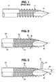
- Fig. 1 is a side view of a prior art guide pin.
- Fig. 3 is an illustration of a method of forming threads on the guide pin shown in Fig. 2.
- a guide pin 20 made according to the present invention, comprises an elongated shaft 22 (only a portion of which is shown in Fig. 2), a threaded portion 24 and a drill end 26.
- Threaded portion 24 includes a number of threads 28 and is characterized by a root diameter 30 and a thread diameter 32.
- the root diameter 30 is defined as the diameter of guide pin 20 at the root or base of each thread 28.
- the thread diameter 32 is equal to the diameter of guide pin 20 at the crest or highest point of each thread 28.
- Fig. 3 illustrates one method of forming threaded portion 24 on guide pin 20 using a standard cutting tool 40.
- Guide pin 20 is rotated along its longitudinal axis 44 by a standard apparatus (not shown) as cutting tool 40 moves along axis 42 to engage pin 20. With pin 20 continuing to rotate, cutting tool 40 travels along pin 20 at a constant speed, thereby forming threads 28.
- drill end 26 is formed in a well known manner using a standard machine tool. Alternatively, drill end 26 may be formed before threads 28 are formed.
- the number of threads 28 can be varied by varying both the speed at which pin 20 is rotated and/or the speed with which cutting tool 20 is moved. It should be noted that Fig. 3 illustrates pin 20 with threads 28 already formed.
- the path or line 42 along which cutting tool 40 travels forms an angle A of 2.5 degrees with longitudinal axis 44 of pin 20.
- the longitudinal axis 41 of cutting tool 40 is perpendicular to path 42. Since path 42 is not parallel to longitudinal axis 44, as cutting tool 40 forms threads 28, the distance between tool 40 and axis 44 of pin 20 will increase. This gradual movement of cutting tool 40 away from longitudinal axis 44 of pin 20 causes the root diameter of the threads being formed to gradually taper from the minimum value at the end of threaded portion 24 closest to drill end 26 to a maximum value that is equal to the diameter of shaft portion 22, as discussed above.
- each thread 28 results in the height of each thread 28 also tapering from a minimum value at the portion of threaded portion 24 closest to shaft 22 to a maximum height exhibited at the portion of threaded portion 24 closest to drill end 26.
- the height of a thread 28 is defined as one half of the difference between the thread diameter 32 and the average of the root diameters on each axial side of the thread under consideration. This difference clearly increases as the threads approach drill end 26, where the threads become higher or more pronounced.
Abstract
Description
Claims (9)
- A guide pin (20) used to penetrate a bone and to guide a cannulated bone screw comprising:an elongated shaft (22) having a constant diameter; andan elongated threaded portion (24) comprising first and second axially separated ends, said first axial end being axially closer to said elongated shaft (24) than said second axial end, said threaded portion (24) having a root diameter (30) that tapers from a maximum value at said first axial end to a minimum value at said second axial end.
- The pin of claim 1 wherein said root diameter (30) of said threaded portion (24) tapers linearly from said first axial end to said second axial end.
- The pin of any preceding claim wherein said first axial end abuts said elongated shaft (22).
- The pin of any preceding claim further comprising a drill end (26) extending axially from said second axial end of said threaded portion such that said drill end (26) is connected to said elongated shaft (22) by said threaded portion (24).
- The pin of any preceding claim wherein said root diameter (30) at said first axial end of said threaded portion (24) is substantially equal to said diameter of said elongated shaft.
- The pin of any preceding claim wherein said threaded portion (24) comprises a plurality of threads (28), each of said threads having a thread height, wherein said thread height of said threads (28) increases from said first axial end to said second axial end.
- The pin of claim 6 wherein said thread height of said threads (28) increases linearly from said first axial end to said second axial end.
- The pin of any preceding claim wherein said diameter of said elongated portion (24) is equal to two millimeters.
- The pin of any preceding claim wherein said elongated threaded portion (24) has a thread diameter (32) that is equal to said diameter of said elongated shaft (22).
Applications Claiming Priority (3)
| Application Number | Priority Date | Filing Date | Title |
|---|---|---|---|
| US832110 | 1992-02-06 | ||
| US07/832,110 US5242447A (en) | 1992-02-06 | 1992-02-06 | Pin with tapered root diameter |
| PCT/US1993/000198 WO1993015681A1 (en) | 1992-02-06 | 1993-01-19 | Pin with tapered root diameter |
Publications (2)
| Publication Number | Publication Date |
|---|---|
| EP0670698A1 EP0670698A1 (en) | 1995-09-13 |
| EP0670698B1 true EP0670698B1 (en) | 1998-03-25 |
Family
ID=25260714
Family Applications (1)
| Application Number | Title | Priority Date | Filing Date |
|---|---|---|---|
| EP93903410A Revoked EP0670698B1 (en) | 1992-02-06 | 1993-01-19 | Pin with tapered root diameter |
Country Status (11)
| Country | Link |
|---|---|
| US (1) | US5242447A (en) |
| EP (1) | EP0670698B1 (en) |
| JP (1) | JP2610391B2 (en) |
| AT (1) | ATE164305T1 (en) |
| AU (1) | AU676671B2 (en) |
| CA (1) | CA2128001C (en) |
| DE (2) | DE69317669T2 (en) |
| DK (1) | DK0670698T3 (en) |
| ES (1) | ES2114035T3 (en) |
| GR (1) | GR3026460T3 (en) |
| WO (1) | WO1993015681A1 (en) |
Families Citing this family (146)
| Publication number | Priority date | Publication date | Assignee | Title |
|---|---|---|---|---|
| CH688222A5 (en) * | 1993-12-07 | 1997-06-30 | Synthes Ag | Bone fixation element. |
| WO1995015727A1 (en) * | 1993-12-08 | 1995-06-15 | Burke Dennis W | Variable pitch bone screw |
| DE19528242A1 (en) * | 1995-08-01 | 1997-02-06 | Roland Dr Dr Streckbein | Instrument for preparing cavities in bone spongiosa for receiving implants - has threaded section, slightly conical, and head for rotating it, forcing bone cavity wall material radially towards outside |
| US5743898A (en) * | 1995-05-12 | 1998-04-28 | Electro-Biology, Inc. | Method and apparatus for external fixation of small bones |
| US5662650A (en) | 1995-05-12 | 1997-09-02 | Electro-Biology, Inc. | Method and apparatus for external fixation of large bones |
| US5976125A (en) * | 1995-08-29 | 1999-11-02 | The Cleveland Clinic Foundation | External distractor/fixator for the management of fractures and dislocations of interphalangeal joints |
| US5899906A (en) * | 1996-01-18 | 1999-05-04 | Synthes (U.S.A.) | Threaded washer |
| US5919193A (en) * | 1996-03-14 | 1999-07-06 | Slavitt; Jerome A. | Method and kit for surgically correcting malformations in digits of a finger or toe |
| US6117162A (en) * | 1996-08-05 | 2000-09-12 | Arthrex, Inc. | Corkscrew suture anchor |
| US6648890B2 (en) | 1996-11-12 | 2003-11-18 | Triage Medical, Inc. | Bone fixation system with radially extendable anchor |
| US5893850A (en) | 1996-11-12 | 1999-04-13 | Cachia; Victor V. | Bone fixation device |
| US20050143734A1 (en) * | 1996-11-12 | 2005-06-30 | Cachia Victor V. | Bone fixation system with radially extendable anchor |
| US6632224B2 (en) * | 1996-11-12 | 2003-10-14 | Triage Medical, Inc. | Bone fixation system |
| US8343186B2 (en) | 2004-04-06 | 2013-01-01 | Arthrex, Inc. | Fully threaded suture anchor with transverse anchor pin |
| US9521999B2 (en) | 2005-09-13 | 2016-12-20 | Arthrex, Inc. | Fully-threaded bioabsorbable suture anchor |
| AUPQ246799A0 (en) * | 1999-08-26 | 1999-09-16 | Australian Surgical Design And Manufacture Pty Limited | Surgical screw and guidewire |
| DE59901812D1 (en) * | 1999-10-21 | 2002-07-25 | Storz Karl Gmbh & Co Kg | interference screw |
| JP2003524493A (en) * | 2000-02-03 | 2003-08-19 | アルファテック マニュファクチャリング, インコーポレイテッド | Intramedullary coupling screw |
| SE518461C2 (en) * | 2001-02-21 | 2002-10-15 | Henrik Hansson | Bone screw, way to make its threads and drill to drill holes for same |
| US6887243B2 (en) | 2001-03-30 | 2005-05-03 | Triage Medical, Inc. | Method and apparatus for bone fixation with secondary compression |
| US6511481B2 (en) | 2001-03-30 | 2003-01-28 | Triage Medical, Inc. | Method and apparatus for fixation of proximal femoral fractures |
| US7235079B2 (en) | 2004-11-18 | 2007-06-26 | Acumed Llc | Composite bone fasteners |
| US6770075B2 (en) | 2001-05-17 | 2004-08-03 | Robert S. Howland | Spinal fixation apparatus with enhanced axial support and methods for use |
| US6685706B2 (en) * | 2001-11-19 | 2004-02-03 | Triage Medical, Inc. | Proximal anchors for bone fixation system |
| US6793678B2 (en) | 2002-06-27 | 2004-09-21 | Depuy Acromed, Inc. | Prosthetic intervertebral motion disc having dampening |
| WO2004008949A2 (en) | 2002-07-19 | 2004-01-29 | Triage Medical, Inc. | Method and apparatus for spinal fixation |
| US7070601B2 (en) | 2003-01-16 | 2006-07-04 | Triage Medical, Inc. | Locking plate for bone anchors |
| ES2295704T3 (en) * | 2003-03-28 | 2008-04-16 | Synthes Gmbh | BLOCKING SCREW. |
| US6951561B2 (en) | 2003-05-06 | 2005-10-04 | Triage Medical, Inc. | Spinal stabilization device |
| US20040230195A1 (en) * | 2003-05-14 | 2004-11-18 | Inion Ltd. | Soft-tissue screw |
| US20050070907A1 (en) * | 2003-09-25 | 2005-03-31 | Abernathie Dennis L. | Method and device for drilling and tapping a bore for a bone screw |
| US7608092B1 (en) | 2004-02-20 | 2009-10-27 | Biomet Sports Medicince, LLC | Method and apparatus for performing meniscus repair |
| US20050276676A1 (en) * | 2004-06-15 | 2005-12-15 | Ofer Mardinger | Orthodpedic or dental device |
| WO2006023793A2 (en) * | 2004-08-20 | 2006-03-02 | Triage Medical, Inc. | Method and apparatus for delivering an agent |
| US8840645B2 (en) | 2004-11-05 | 2014-09-23 | Biomet Sports Medicine, Llc | Method and apparatus for coupling soft tissue to a bone |
| US8361113B2 (en) | 2006-02-03 | 2013-01-29 | Biomet Sports Medicine, Llc | Method and apparatus for coupling soft tissue to a bone |
| US20060189993A1 (en) | 2004-11-09 | 2006-08-24 | Arthrotek, Inc. | Soft tissue conduit device |
| US9017381B2 (en) | 2007-04-10 | 2015-04-28 | Biomet Sports Medicine, Llc | Adjustable knotless loops |
| US7749250B2 (en) | 2006-02-03 | 2010-07-06 | Biomet Sports Medicine, Llc | Soft tissue repair assembly and associated method |
| US8137382B2 (en) | 2004-11-05 | 2012-03-20 | Biomet Sports Medicine, Llc | Method and apparatus for coupling anatomical features |
| US8303604B2 (en) | 2004-11-05 | 2012-11-06 | Biomet Sports Medicine, Llc | Soft tissue repair device and method |
| US8128658B2 (en) | 2004-11-05 | 2012-03-06 | Biomet Sports Medicine, Llc | Method and apparatus for coupling soft tissue to bone |
| US8088130B2 (en) | 2006-02-03 | 2012-01-03 | Biomet Sports Medicine, Llc | Method and apparatus for coupling soft tissue to a bone |
| US8298262B2 (en) | 2006-02-03 | 2012-10-30 | Biomet Sports Medicine, Llc | Method for tissue fixation |
| US8118836B2 (en) | 2004-11-05 | 2012-02-21 | Biomet Sports Medicine, Llc | Method and apparatus for coupling soft tissue to a bone |
| US7909851B2 (en) | 2006-02-03 | 2011-03-22 | Biomet Sports Medicine, Llc | Soft tissue repair device and associated methods |
| US7905904B2 (en) | 2006-02-03 | 2011-03-15 | Biomet Sports Medicine, Llc | Soft tissue repair device and associated methods |
| US7905903B2 (en) | 2006-02-03 | 2011-03-15 | Biomet Sports Medicine, Llc | Method for tissue fixation |
| US9801708B2 (en) | 2004-11-05 | 2017-10-31 | Biomet Sports Medicine, Llc | Method and apparatus for coupling soft tissue to a bone |
| US7601165B2 (en) | 2006-09-29 | 2009-10-13 | Biomet Sports Medicine, Llc | Method and apparatus for forming a self-locking adjustable suture loop |
| US7857830B2 (en) | 2006-02-03 | 2010-12-28 | Biomet Sports Medicine, Llc | Soft tissue repair and conduit device |
| US8998949B2 (en) | 2004-11-09 | 2015-04-07 | Biomet Sports Medicine, Llc | Soft tissue conduit device |
| US7914539B2 (en) | 2004-11-09 | 2011-03-29 | Biomet Sports Medicine, Llc | Tissue fixation device |
| US8034090B2 (en) | 2004-11-09 | 2011-10-11 | Biomet Sports Medicine, Llc | Tissue fixation device |
| EP1762186B1 (en) | 2005-09-12 | 2011-02-16 | Arthrex, Inc. | Suture anchor with eyelet |
| US9149267B2 (en) | 2006-02-03 | 2015-10-06 | Biomet Sports Medicine, Llc | Method and apparatus for coupling soft tissue to a bone |
| US8251998B2 (en) | 2006-08-16 | 2012-08-28 | Biomet Sports Medicine, Llc | Chondral defect repair |
| US8506597B2 (en) | 2011-10-25 | 2013-08-13 | Biomet Sports Medicine, Llc | Method and apparatus for interosseous membrane reconstruction |
| US8968364B2 (en) | 2006-02-03 | 2015-03-03 | Biomet Sports Medicine, Llc | Method and apparatus for fixation of an ACL graft |
| US8597327B2 (en) | 2006-02-03 | 2013-12-03 | Biomet Manufacturing, Llc | Method and apparatus for sternal closure |
| US9271713B2 (en) | 2006-02-03 | 2016-03-01 | Biomet Sports Medicine, Llc | Method and apparatus for tensioning a suture |
| US9078644B2 (en) | 2006-09-29 | 2015-07-14 | Biomet Sports Medicine, Llc | Fracture fixation device |
| US8562647B2 (en) | 2006-09-29 | 2013-10-22 | Biomet Sports Medicine, Llc | Method and apparatus for securing soft tissue to bone |
| US11259792B2 (en) | 2006-02-03 | 2022-03-01 | Biomet Sports Medicine, Llc | Method and apparatus for coupling anatomical features |
| US8652171B2 (en) | 2006-02-03 | 2014-02-18 | Biomet Sports Medicine, Llc | Method and apparatus for soft tissue fixation |
| US8574235B2 (en) | 2006-02-03 | 2013-11-05 | Biomet Sports Medicine, Llc | Method for trochanteric reattachment |
| US8936621B2 (en) | 2006-02-03 | 2015-01-20 | Biomet Sports Medicine, Llc | Method and apparatus for forming a self-locking adjustable loop |
| US8771352B2 (en) | 2011-05-17 | 2014-07-08 | Biomet Sports Medicine, Llc | Method and apparatus for tibial fixation of an ACL graft |
| US8562645B2 (en) | 2006-09-29 | 2013-10-22 | Biomet Sports Medicine, Llc | Method and apparatus for forming a self-locking adjustable loop |
| US7959650B2 (en) | 2006-09-29 | 2011-06-14 | Biomet Sports Medicine, Llc | Adjustable knotless loops |
| US11311287B2 (en) | 2006-02-03 | 2022-04-26 | Biomet Sports Medicine, Llc | Method for tissue fixation |
| US8801783B2 (en) | 2006-09-29 | 2014-08-12 | Biomet Sports Medicine, Llc | Prosthetic ligament system for knee joint |
| US9538998B2 (en) | 2006-02-03 | 2017-01-10 | Biomet Sports Medicine, Llc | Method and apparatus for fracture fixation |
| US8652172B2 (en) | 2006-02-03 | 2014-02-18 | Biomet Sports Medicine, Llc | Flexible anchors for tissue fixation |
| US10517587B2 (en) | 2006-02-03 | 2019-12-31 | Biomet Sports Medicine, Llc | Method and apparatus for forming a self-locking adjustable loop |
| WO2008021474A2 (en) * | 2006-08-16 | 2008-02-21 | Incumed, Incorporated | Composite interference screw for attaching a graft ligament to a bone, and other apparatus for making attachments to bone |
| US8894661B2 (en) * | 2007-08-16 | 2014-11-25 | Smith & Nephew, Inc. | Helicoil interference fixation system for attaching a graft ligament to a bone |
| US9918826B2 (en) | 2006-09-29 | 2018-03-20 | Biomet Sports Medicine, Llc | Scaffold for spring ligament repair |
| US8672969B2 (en) | 2006-09-29 | 2014-03-18 | Biomet Sports Medicine, Llc | Fracture fixation device |
| US8500818B2 (en) | 2006-09-29 | 2013-08-06 | Biomet Manufacturing, Llc | Knee prosthesis assembly with ligament link |
| US11259794B2 (en) | 2006-09-29 | 2022-03-01 | Biomet Sports Medicine, Llc | Method for implanting soft tissue |
| WO2008070863A2 (en) | 2006-12-07 | 2008-06-12 | Interventional Spine, Inc. | Intervertebral implant |
| US8128671B2 (en) * | 2007-04-04 | 2012-03-06 | Warsaw Orthopedic, Inc. | Variable flank bone screw |
| US7998176B2 (en) | 2007-06-08 | 2011-08-16 | Interventional Spine, Inc. | Method and apparatus for spinal stabilization |
| US8900307B2 (en) | 2007-06-26 | 2014-12-02 | DePuy Synthes Products, LLC | Highly lordosed fusion cage |
| JP5441922B2 (en) | 2008-01-17 | 2014-03-12 | ジンテス ゲゼルシャフト ミット ベシュレンクテル ハフツング | Inflatable intervertebral implant and related manufacturing method |
| EP2262449B1 (en) | 2008-04-05 | 2020-03-11 | Synthes GmbH | Expandable intervertebral implant |
| US8808292B2 (en) * | 2008-11-11 | 2014-08-19 | Zimmer Gmbh | Orthopedic screw |
| US9526620B2 (en) | 2009-03-30 | 2016-12-27 | DePuy Synthes Products, Inc. | Zero profile spinal fusion cage |
| US8282676B2 (en) * | 2009-05-28 | 2012-10-09 | Griffin T Hall | Tapered thread root transition on cortical bone fastener |
| US8343227B2 (en) | 2009-05-28 | 2013-01-01 | Biomet Manufacturing Corp. | Knee prosthesis assembly with ligament link |
| US8414629B2 (en) * | 2009-11-20 | 2013-04-09 | T. Hall Griffin | Limiting radial preloads in securing an orthopedic fastener |
| US8409261B2 (en) * | 2009-11-20 | 2013-04-02 | T. Hall Griffin | Engaging predetermined radial preloads in securing an orthopedic fastener |
| US8771325B2 (en) * | 2009-11-20 | 2014-07-08 | T. Hall Griffin | Tapered threaded orthopedic fastener engaging predetermined radial preloads |
| US9393129B2 (en) | 2009-12-10 | 2016-07-19 | DePuy Synthes Products, Inc. | Bellows-like expandable interbody fusion cage |
| WO2011112776A1 (en) | 2010-03-10 | 2011-09-15 | Smith & Nephew, Inc. | Composite interference screws and drivers |
| US9579188B2 (en) | 2010-03-10 | 2017-02-28 | Smith & Nephew, Inc. | Anchor having a controlled driver orientation |
| US9775702B2 (en) | 2010-03-10 | 2017-10-03 | Smith & Nephew, Inc. | Composite interference screws and drivers |
| US9308080B2 (en) | 2010-03-10 | 2016-04-12 | Smith & Nephew Inc. | Composite interference screws and drivers |
| US8845733B2 (en) | 2010-06-24 | 2014-09-30 | DePuy Synthes Products, LLC | Lateral spondylolisthesis reduction cage |
| US8979860B2 (en) | 2010-06-24 | 2015-03-17 | DePuy Synthes Products. LLC | Enhanced cage insertion device |
| TW201215379A (en) | 2010-06-29 | 2012-04-16 | Synthes Gmbh | Distractible intervertebral implant |
| US9402732B2 (en) | 2010-10-11 | 2016-08-02 | DePuy Synthes Products, Inc. | Expandable interspinous process spacer implant |
| MX344606B (en) | 2011-03-11 | 2016-12-20 | Smith & Nephew Inc | Trephine. |
| KR20140043768A (en) | 2011-06-07 | 2014-04-10 | 스미스 앤드 네퓨, 인크. | Surgical anchor delivery system |
| US9357991B2 (en) | 2011-11-03 | 2016-06-07 | Biomet Sports Medicine, Llc | Method and apparatus for stitching tendons |
| US9381013B2 (en) | 2011-11-10 | 2016-07-05 | Biomet Sports Medicine, Llc | Method for coupling soft tissue to a bone |
| US9357992B2 (en) | 2011-11-10 | 2016-06-07 | Biomet Sports Medicine, Llc | Method for coupling soft tissue to a bone |
| US9370350B2 (en) | 2011-11-10 | 2016-06-21 | Biomet Sports Medicine, Llc | Apparatus for coupling soft tissue to a bone |
| US9259217B2 (en) | 2012-01-03 | 2016-02-16 | Biomet Manufacturing, Llc | Suture Button |
| EP2877127B1 (en) | 2012-07-26 | 2019-08-21 | Synthes GmbH | Expandable implant |
| US20140067069A1 (en) | 2012-08-30 | 2014-03-06 | Interventional Spine, Inc. | Artificial disc |
| US9522070B2 (en) | 2013-03-07 | 2016-12-20 | Interventional Spine, Inc. | Intervertebral implant |
| US9757119B2 (en) | 2013-03-08 | 2017-09-12 | Biomet Sports Medicine, Llc | Visual aid for identifying suture limbs arthroscopically |
| US9918827B2 (en) | 2013-03-14 | 2018-03-20 | Biomet Sports Medicine, Llc | Scaffold for spring ligament repair |
| US9155531B2 (en) | 2013-03-15 | 2015-10-13 | Smith & Nephew, Inc. | Miniaturized dual drive open architecture suture anchor |
| WO2014169058A1 (en) | 2013-04-09 | 2014-10-16 | Smith & Nephew, Inc | Open-architecture interference screw |
| US9522028B2 (en) | 2013-07-03 | 2016-12-20 | Interventional Spine, Inc. | Method and apparatus for sacroiliac joint fixation |
| US10136886B2 (en) | 2013-12-20 | 2018-11-27 | Biomet Sports Medicine, Llc | Knotless soft tissue devices and techniques |
| US9615822B2 (en) | 2014-05-30 | 2017-04-11 | Biomet Sports Medicine, Llc | Insertion tools and method for soft anchor |
| US9700291B2 (en) | 2014-06-03 | 2017-07-11 | Biomet Sports Medicine, Llc | Capsule retractor |
| US10039543B2 (en) | 2014-08-22 | 2018-08-07 | Biomet Sports Medicine, Llc | Non-sliding soft anchor |
| US9955980B2 (en) | 2015-02-24 | 2018-05-01 | Biomet Sports Medicine, Llc | Anatomic soft tissue repair |
| US11426290B2 (en) | 2015-03-06 | 2022-08-30 | DePuy Synthes Products, Inc. | Expandable intervertebral implant, system, kit and method |
| US9974534B2 (en) | 2015-03-31 | 2018-05-22 | Biomet Sports Medicine, Llc | Suture anchor with soft anchor of electrospun fibers |
| US9913727B2 (en) | 2015-07-02 | 2018-03-13 | Medos International Sarl | Expandable implant |
| WO2018002711A2 (en) | 2016-06-28 | 2018-01-04 | Eit Emerging Implant Technologies Gmbh | Expandable, angularly adjustable intervertebral cages |
| WO2018002715A2 (en) | 2016-06-28 | 2018-01-04 | Eit Emerging Implant Technologies Gmbh | Expandable and angularly adjustable articulating intervertebral cages |
| US10537436B2 (en) | 2016-11-01 | 2020-01-21 | DePuy Synthes Products, Inc. | Curved expandable cage |
| US10888433B2 (en) | 2016-12-14 | 2021-01-12 | DePuy Synthes Products, Inc. | Intervertebral implant inserter and related methods |
| US10398563B2 (en) | 2017-05-08 | 2019-09-03 | Medos International Sarl | Expandable cage |
| US11344424B2 (en) | 2017-06-14 | 2022-05-31 | Medos International Sarl | Expandable intervertebral implant and related methods |
| US10940016B2 (en) | 2017-07-05 | 2021-03-09 | Medos International Sarl | Expandable intervertebral fusion cage |
| CN108030542B (en) * | 2018-01-30 | 2020-06-19 | 芜湖东旭威宇医疗器械科技有限公司 | Easy-to-insert bone needle |
| US11446156B2 (en) | 2018-10-25 | 2022-09-20 | Medos International Sarl | Expandable intervertebral implant, inserter instrument, and related methods |
| RU192512U1 (en) * | 2018-12-14 | 2019-09-18 | Федеральное государственное бюджетное образовательное учреждение высшего образования "Саратовский государственный технический университет имени Гагарина Ю.А." (СГТУ имени Гагарина Ю.А.) | NEEDLE FOR OSTEOSYNTHESIS |
| RU189427U1 (en) * | 2018-12-24 | 2019-05-22 | Федеральное государственное бюджетное образовательное учреждение высшего образования "Саратовский государственный технический университет имени Гагарина Ю.А." (СГТУ имени Гагарина Ю.А.) | SPEAKER FOR OSTEOSYNTHESIS |
| RU189431U1 (en) * | 2018-12-28 | 2019-05-22 | Федеральное государственное бюджетное образовательное учреждение высшего образования "Саратовский государственный технический университет имени Гагарина Ю.А." (СГТУ имени Гагарина Ю.А.) | SPEAKER FOR OSTEOSYNTHESIS |
| RU189270U1 (en) * | 2018-12-28 | 2019-05-17 | Федеральное государственное бюджетное образовательное учреждение высшего образования "Саратовский государственный технический университет имени Гагарина Ю.А." (СГТУ имени Гагарина Ю.А.) | SPEAKER FOR OSTEOSYNTHESIS WITH BIOACTIVE COATING |
| RU189430U1 (en) * | 2018-12-28 | 2019-05-22 | Федеральное государственное бюджетное образовательное учреждение высшего образования "Саратовский государственный технический университет имени Гагарина Ю.А." (СГТУ имени Гагарина Ю.А.) | SPEAKER FOR OSTEOSYNTHESIS WITH BIOACTIVE COATING |
| RU189624U1 (en) * | 2018-12-28 | 2019-05-29 | Федеральное государственное бюджетное образовательное учреждение высшего образования "Саратовский государственный технический университет имени Гагарина Ю.А." (СГТУ имени Гагарина Ю.А.) | SPEAKER FOR OSTEOSYNTHESIS WITH BIOACTIVE COATING |
| RU189273U1 (en) * | 2018-12-28 | 2019-05-17 | Федеральное государственное бюджетное образовательное учреждение высшего образования "Саратовский государственный технический университет имени Гагарина Ю.А." (СГТУ имени Гагарина Ю.А.) | SPEAKER FOR OSTEOSYNTHESIS WITH BIOACTIVE COATING |
| RU189274U1 (en) * | 2018-12-29 | 2019-05-17 | Федеральное государственное бюджетное образовательное учреждение высшего образования "Саратовский государственный технический университет имени Гагарина Ю.А." (СГТУ имени Гагарина Ю.А.) | SPEAKER FOR OSTEOSYNTHESIS |
| US11426286B2 (en) | 2020-03-06 | 2022-08-30 | Eit Emerging Implant Technologies Gmbh | Expandable intervertebral implant |
| US11850160B2 (en) | 2021-03-26 | 2023-12-26 | Medos International Sarl | Expandable lordotic intervertebral fusion cage |
| US11752009B2 (en) | 2021-04-06 | 2023-09-12 | Medos International Sarl | Expandable intervertebral fusion cage |
Family Cites Families (9)
| Publication number | Priority date | Publication date | Assignee | Title |
|---|---|---|---|---|
| US74489A (en) * | 1868-02-18 | Improvement in wood-soeews | ||
| US3045523A (en) * | 1960-08-25 | 1962-07-24 | Nd Edgar Reed | Drill point screw having interrupted leading end threads formed by a flat chordal surface |
| CH566127A5 (en) * | 1973-05-18 | 1975-09-15 | Sulzer Ag | Implement for removing cement from bone implant - has threaded tip and handle on other end |
| US4463753A (en) * | 1980-01-04 | 1984-08-07 | Gustilo Ramon B | Compression bone screw |
| US4414966A (en) * | 1981-04-09 | 1983-11-15 | Ace Orthopedic Manufacturing, Inc. | Fixation pin |
| CH671150A5 (en) * | 1986-10-13 | 1989-08-15 | Jaquet Orthopedie | |
| DE3708638A1 (en) * | 1987-03-17 | 1988-09-29 | Grafelmann Hans L | SELF-CUTTING SCREW-IN BONE IMPLANT FOR DENTAL PURPOSES |
| FR2642958A1 (en) * | 1989-02-16 | 1990-08-17 | Louyot Comptoir Lyon Alemand | SYSTEM FOR IMPLEMENTING SURGICAL INTERVENTIONS, SUCH AS THE TREATMENT OF FRACTURES OF THE VERTEBRAL COLUMN OR OF DEGENERATIVE OR TUMORAL LESIONS |
| DE4012506A1 (en) * | 1990-04-12 | 1991-10-17 | Mecron Med Prod Gmbh | BONE SCREW |
-
1992
- 1992-02-06 US US07/832,110 patent/US5242447A/en not_active Expired - Lifetime
-
1993
- 1993-01-19 EP EP93903410A patent/EP0670698B1/en not_active Revoked
- 1993-01-19 CA CA002128001A patent/CA2128001C/en not_active Expired - Lifetime
- 1993-01-19 JP JP5514061A patent/JP2610391B2/en not_active Expired - Fee Related
- 1993-01-19 WO PCT/US1993/000198 patent/WO1993015681A1/en not_active Application Discontinuation
- 1993-01-19 AT AT93903410T patent/ATE164305T1/en not_active IP Right Cessation
- 1993-01-19 ES ES93903410T patent/ES2114035T3/en not_active Expired - Lifetime
- 1993-01-19 DE DE69317669T patent/DE69317669T2/en not_active Revoked
- 1993-01-19 DK DK93903410.4T patent/DK0670698T3/en active
- 1993-01-19 AU AU34684/93A patent/AU676671B2/en not_active Expired
- 1993-01-19 DE DE9390026U patent/DE9390026U1/en not_active Expired - Lifetime
-
1998
- 1998-03-27 GR GR980400644T patent/GR3026460T3/en unknown
Also Published As
| Publication number | Publication date |
|---|---|
| ATE164305T1 (en) | 1998-04-15 |
| DE69317669T2 (en) | 1998-07-09 |
| ES2114035T3 (en) | 1998-05-16 |
| AU3468493A (en) | 1993-09-03 |
| DK0670698T3 (en) | 1998-04-27 |
| WO1993015681A1 (en) | 1993-08-19 |
| GR3026460T3 (en) | 1998-06-30 |
| AU676671B2 (en) | 1997-03-20 |
| CA2128001A1 (en) | 1993-08-19 |
| JPH06511178A (en) | 1994-12-15 |
| JP2610391B2 (en) | 1997-05-14 |
| US5242447A (en) | 1993-09-07 |
| EP0670698A1 (en) | 1995-09-13 |
| DE9390026U1 (en) | 1994-10-13 |
| CA2128001C (en) | 1999-11-30 |
| DE69317669D1 (en) | 1998-04-30 |
Similar Documents
| Publication | Publication Date | Title |
|---|---|---|
| EP0670698B1 (en) | Pin with tapered root diameter | |
| US4858601A (en) | Adjustable compression bone screw | |
| EP0746253B1 (en) | Tapered bone screw with continuously varying pitch | |
| US5334204A (en) | Fixation screw | |
| US6306140B1 (en) | Bone screw | |
| EP0550814B1 (en) | Anchorage nail for the treatment of hollow bone fractures | |
| US5129901A (en) | Cannulated orthopedic screw | |
| US6551323B2 (en) | Method of making a bonescrew | |
| US4940467A (en) | Variable length fixation device | |
| US6984235B2 (en) | System for fusing joints | |
| US5871486A (en) | Variable pitch bone screw | |
| WO1999055248A1 (en) | Adjustable length orthopedic fixation device | |
| KR100845599B1 (en) | Bone Screw | |
| EP0359793A4 (en) | Variable length fixation device | |
| US20210322074A1 (en) | Orthopaedic bone stabilisation device | |
| US6004321A (en) | Cannulated screw retraction apparatus and method of retraction | |
| WO1995015727A1 (en) | Variable pitch bone screw | |
| JPS62243551A (en) | Fixing apuncture pin in external bone connection technique | |
| KR101670273B1 (en) | Locking fixing system for orthopedic implants | |
| US20210000509A1 (en) | Pin fastener with removeable drill bit for bone fixator | |
| KR101849380B1 (en) | Coordination locking fixing system for orthopedic implant | |
| JP3722438B2 (en) | Internal fixation member for femoral neck fracture treatment | |
| US11478277B2 (en) | Compression nut and a system for treating a bone | |
| USRE28502E (en) | Intramedullary rod | |
| KR20030037616A (en) | Free length hip pin |
Legal Events
| Date | Code | Title | Description |
|---|---|---|---|
| PUAI | Public reference made under article 153(3) epc to a published international application that has entered the european phase |
Free format text: ORIGINAL CODE: 0009012 |
|
| 17P | Request for examination filed |
Effective date: 19940727 |
|
| AK | Designated contracting states |
Kind code of ref document: A1 Designated state(s): AT BE CH DE DK ES FR GB GR IE IT LI LU NL PT SE |
|
| 17Q | First examination report despatched |
Effective date: 19960205 |
|
| GRAG | Despatch of communication of intention to grant |
Free format text: ORIGINAL CODE: EPIDOS AGRA |
|
| GRAG | Despatch of communication of intention to grant |
Free format text: ORIGINAL CODE: EPIDOS AGRA |
|
| GRAH | Despatch of communication of intention to grant a patent |
Free format text: ORIGINAL CODE: EPIDOS IGRA |
|
| GRAH | Despatch of communication of intention to grant a patent |
Free format text: ORIGINAL CODE: EPIDOS IGRA |
|
| GRAA | (expected) grant |
Free format text: ORIGINAL CODE: 0009210 |
|
| AK | Designated contracting states |
Kind code of ref document: B1 Designated state(s): AT BE CH DE DK ES FR GB GR IE IT LI LU NL PT SE |
|
| REF | Corresponds to: |
Ref document number: 164305 Country of ref document: AT Date of ref document: 19980415 Kind code of ref document: T |
|
| REG | Reference to a national code |
Ref country code: CH Ref legal event code: EP |
|
| REG | Reference to a national code |
Ref country code: CH Ref legal event code: NV Representative=s name: E. BLUM & CO. PATENTANWAELTE |
|
| REG | Reference to a national code |
Ref country code: DK Ref legal event code: T3 |
|
| REF | Corresponds to: |
Ref document number: 69317669 Country of ref document: DE Date of ref document: 19980430 |
|
| ITF | It: translation for a ep patent filed |
Owner name: MODIANO & ASSOCIATI S.R.L. |
|
| REG | Reference to a national code |
Ref country code: ES Ref legal event code: FG2A Ref document number: 2114035 Country of ref document: ES Kind code of ref document: T3 |
|
| ET | Fr: translation filed | ||
| REG | Reference to a national code |
Ref country code: IE Ref legal event code: FG4D Free format text: 79504 |
|
| REG | Reference to a national code |
Ref country code: PT Ref legal event code: SC4A Free format text: AVAILABILITY OF NATIONAL TRANSLATION Effective date: 19980527 |
|
| PGFP | Annual fee paid to national office [announced via postgrant information from national office to epo] |
Ref country code: PT Payment date: 19980902 Year of fee payment: 7 |
|
| PGFP | Annual fee paid to national office [announced via postgrant information from national office to epo] |
Ref country code: GR Payment date: 19981124 Year of fee payment: 7 |
|
| PLBQ | Unpublished change to opponent data |
Free format text: ORIGINAL CODE: EPIDOS OPPO |
|
| PGFP | Annual fee paid to national office [announced via postgrant information from national office to epo] |
Ref country code: SE Payment date: 19981203 Year of fee payment: 7 |
|
| PLBI | Opposition filed |
Free format text: ORIGINAL CODE: 0009260 |
|
| PGFP | Annual fee paid to national office [announced via postgrant information from national office to epo] |
Ref country code: CH Payment date: 19981215 Year of fee payment: 7 |
|
| PLBQ | Unpublished change to opponent data |
Free format text: ORIGINAL CODE: EPIDOS OPPO |
|
| PLBI | Opposition filed |
Free format text: ORIGINAL CODE: 0009260 |
|
| PGFP | Annual fee paid to national office [announced via postgrant information from national office to epo] |
Ref country code: DK Payment date: 19990115 Year of fee payment: 7 |
|
| PGFP | Annual fee paid to national office [announced via postgrant information from national office to epo] |
Ref country code: IE Payment date: 19990118 Year of fee payment: 7 |
|
| 26 | Opposition filed |
Opponent name: SYNTHES AG CHUR Effective date: 19981124 |
|
| PGFP | Annual fee paid to national office [announced via postgrant information from national office to epo] |
Ref country code: ES Payment date: 19990120 Year of fee payment: 7 |
|
| PGFP | Annual fee paid to national office [announced via postgrant information from national office to epo] |
Ref country code: BE Payment date: 19990125 Year of fee payment: 7 Ref country code: AT Payment date: 19990125 Year of fee payment: 7 |
|
| PGFP | Annual fee paid to national office [announced via postgrant information from national office to epo] |
Ref country code: LU Payment date: 19990126 Year of fee payment: 7 |
|
| PGFP | Annual fee paid to national office [announced via postgrant information from national office to epo] |
Ref country code: DE Payment date: 19990128 Year of fee payment: 7 |
|
| PGFP | Annual fee paid to national office [announced via postgrant information from national office to epo] |
Ref country code: NL Payment date: 19990129 Year of fee payment: 7 |
|
| PLBF | Reply of patent proprietor to notice(s) of opposition |
Free format text: ORIGINAL CODE: EPIDOS OBSO |
|
| 26 | Opposition filed |
Opponent name: AESCULAP AG & CO. KG Effective date: 19981218 Opponent name: SYNTHES AG CHUR Effective date: 19981124 |
|
| NLR1 | Nl: opposition has been filed with the epo |
Opponent name: SYNTHES AG CHUR |
|
| NLR1 | Nl: opposition has been filed with the epo |
Opponent name: AESCULAP AG & CO. KG Opponent name: SYNTHES AG CHUR |
|
| PLBF | Reply of patent proprietor to notice(s) of opposition |
Free format text: ORIGINAL CODE: EPIDOS OBSO |
|
| RDAH | Patent revoked |
Free format text: ORIGINAL CODE: EPIDOS REVO |
|
| PGFP | Annual fee paid to national office [announced via postgrant information from national office to epo] |
Ref country code: GB Payment date: 19991202 Year of fee payment: 8 |
|
| PGFP | Annual fee paid to national office [announced via postgrant information from national office to epo] |
Ref country code: FR Payment date: 19991217 Year of fee payment: 8 |
|
| REG | Reference to a national code |
Ref country code: CH Ref legal event code: PUE Owner name: MTG DIVESTITURES INC. TRANSFER- STRYKER TECHNOLOGI Ref country code: CH Ref legal event code: PFA Free format text: HOWMEDICA INC. TRANSFER- MTG DIVESTITURES INC. |
|
| RDAG | Patent revoked |
Free format text: ORIGINAL CODE: 0009271 |
|
| STAA | Information on the status of an ep patent application or granted ep patent |
Free format text: STATUS: PATENT REVOKED |
|
| 27W | Patent revoked |
Effective date: 19991118 |
|
| GBPR | Gb: patent revoked under art. 102 of the ep convention designating the uk as contracting state |
Free format text: 991118 |
|
| REG | Reference to a national code |
Ref country code: CH Ref legal event code: PL |
|
| NLR2 | Nl: decision of opposition | ||
| NLS | Nl: assignments of ep-patents |
Owner name: STRYKER TECHNOLOGIES CORPORATION |
|
| NLT1 | Nl: modifications of names registered in virtue of documents presented to the patent office pursuant to art. 16 a, paragraph 1 |
Owner name: MTG DIVESTITURES INC. |
|
| REG | Reference to a national code |
Ref country code: PT Ref legal event code: MF4A Effective date: 20000322 |
|
| REG | Reference to a national code |
Ref country code: IE Ref legal event code: MM4A |
|
| BECH | Be: change of holder |
Free format text: 20000201 *STRYKER TECHNOLOGIES CORP. |