EP0668710A2 - Electric heating apparatus - Google Patents
Electric heating apparatus Download PDFInfo
- Publication number
- EP0668710A2 EP0668710A2 EP94120383A EP94120383A EP0668710A2 EP 0668710 A2 EP0668710 A2 EP 0668710A2 EP 94120383 A EP94120383 A EP 94120383A EP 94120383 A EP94120383 A EP 94120383A EP 0668710 A2 EP0668710 A2 EP 0668710A2
- Authority
- EP
- European Patent Office
- Prior art keywords
- heating element
- sheets
- heat
- housing
- heater according
- Prior art date
- Legal status (The legal status is an assumption and is not a legal conclusion. Google has not performed a legal analysis and makes no representation as to the accuracy of the status listed.)
- Granted
Links
- 238000005485 electric heating Methods 0.000 title description 2
- 238000010438 heat treatment Methods 0.000 claims abstract description 94
- 239000000919 ceramic Substances 0.000 claims abstract description 23
- 238000007654 immersion Methods 0.000 claims abstract description 12
- 229920003023 plastic Polymers 0.000 claims description 8
- 239000004033 plastic Substances 0.000 claims description 8
- 239000007788 liquid Substances 0.000 claims description 5
- 238000005496 tempering Methods 0.000 claims description 2
- 229910010293 ceramic material Inorganic materials 0.000 abstract 1
- 238000012546 transfer Methods 0.000 description 13
- 230000008901 benefit Effects 0.000 description 10
- 239000002184 metal Substances 0.000 description 9
- 230000004044 response Effects 0.000 description 9
- 239000011521 glass Substances 0.000 description 8
- 238000004519 manufacturing process Methods 0.000 description 8
- XLYOFNOQVPJJNP-UHFFFAOYSA-N water Substances O XLYOFNOQVPJJNP-UHFFFAOYSA-N 0.000 description 8
- 239000000463 material Substances 0.000 description 5
- 238000010292 electrical insulation Methods 0.000 description 4
- 238000005266 casting Methods 0.000 description 3
- 230000007246 mechanism Effects 0.000 description 3
- 229920001296 polysiloxane Polymers 0.000 description 3
- 241001465754 Metazoa Species 0.000 description 2
- 238000011161 development Methods 0.000 description 2
- 235000013305 food Nutrition 0.000 description 2
- 238000009413 insulation Methods 0.000 description 2
- 235000000396 iron Nutrition 0.000 description 2
- 238000013021 overheating Methods 0.000 description 2
- 230000005855 radiation Effects 0.000 description 2
- 230000001105 regulatory effect Effects 0.000 description 2
- 239000004576 sand Substances 0.000 description 2
- 229920002379 silicone rubber Polymers 0.000 description 2
- 239000004945 silicone rubber Substances 0.000 description 2
- 235000012773 waffles Nutrition 0.000 description 2
- 238000005452 bending Methods 0.000 description 1
- 230000033228 biological regulation Effects 0.000 description 1
- 230000008859 change Effects 0.000 description 1
- 238000010276 construction Methods 0.000 description 1
- 238000013461 design Methods 0.000 description 1
- 230000005611 electricity Effects 0.000 description 1
- 230000017525 heat dissipation Effects 0.000 description 1
- 238000003780 insertion Methods 0.000 description 1
- 230000037431 insertion Effects 0.000 description 1
- 239000011810 insulating material Substances 0.000 description 1
- 229910044991 metal oxide Inorganic materials 0.000 description 1
- 150000004706 metal oxides Chemical class 0.000 description 1
- 239000000203 mixture Substances 0.000 description 1
- 238000004382 potting Methods 0.000 description 1
- 238000009420 retrofitting Methods 0.000 description 1
- 239000011265 semifinished product Substances 0.000 description 1
- 230000035945 sensitivity Effects 0.000 description 1
- 229910000679 solder Inorganic materials 0.000 description 1
- 238000005476 soldering Methods 0.000 description 1
- 239000004575 stone Substances 0.000 description 1
- 230000007704 transition Effects 0.000 description 1
- 238000010792 warming Methods 0.000 description 1
Images


Classifications
-
- H—ELECTRICITY
- H05—ELECTRIC TECHNIQUES NOT OTHERWISE PROVIDED FOR
- H05B—ELECTRIC HEATING; ELECTRIC LIGHT SOURCES NOT OTHERWISE PROVIDED FOR; CIRCUIT ARRANGEMENTS FOR ELECTRIC LIGHT SOURCES, IN GENERAL
- H05B3/00—Ohmic-resistance heating
- H05B3/78—Heating arrangements specially adapted for immersion heating
- H05B3/80—Portable immersion heaters
-
- H—ELECTRICITY
- H05—ELECTRIC TECHNIQUES NOT OTHERWISE PROVIDED FOR
- H05B—ELECTRIC HEATING; ELECTRIC LIGHT SOURCES NOT OTHERWISE PROVIDED FOR; CIRCUIT ARRANGEMENTS FOR ELECTRIC LIGHT SOURCES, IN GENERAL
- H05B3/00—Ohmic-resistance heating
- H05B3/10—Heating elements characterised by the composition or nature of the materials or by the arrangement of the conductor
- H05B3/12—Heating elements characterised by the composition or nature of the materials or by the arrangement of the conductor characterised by the composition or nature of the conductive material
- H05B3/14—Heating elements characterised by the composition or nature of the materials or by the arrangement of the conductor characterised by the composition or nature of the conductive material the material being non-metallic
- H05B3/141—Conductive ceramics, e.g. metal oxides, metal carbides, barium titanate, ferrites, zirconia, vitrous compounds
Definitions
- the present invention relates to an electric heating device, in particular in the form of an immersion body for heating and / or tempering liquids, with at least one heating element which heats up as a result of a current flowing through and emits heat to its surroundings, the at least one heating element being made of heating ceramic and is housed in a thermally conductive, electrically insulating housing, with which it is in a thermally conductive connection, and the heating element is clamped between two electrically conductive sheets or plates, via which the current supply takes place.
- the known heater comprises a sleeve made of thermally conductive silicone rubber, in which two spaced-apart guide channels are provided, which extend in the rear region of the sleeve and each receive a contact plate.
- a PTC heating element is clamped between the two contact plates, which is supplied with current via the two contact plates.
- the sleeve is closed with a holding body, which also serves as a strain relief for the leads leading to the contact plates.
- This heater is designed as a heating cartridge and is to be inserted into devices to be heated. Since the contact plates and the PTC heating element are completely enclosed by the sleeve or the holding body, the heat conduction from the PTC heating element to the outside is carried out longitudinally and transversely to this sleeve, as a result of which the heat is transferred from the PTC heating element to the object to be heated is determined by the heat conduction in the silicone rubber and is unsatisfactory, which is considered a disadvantage.
- a further disadvantage is that the sleeve itself must be geometrically adapted to the dimensions of the PTC heating element used, so that the resilient clamping of the PTC heating element between the flat contact plates guided in the guide channels is sufficiently secure that the heat transfer from the PTC Heating element to the contact plates is sufficient. If the geometric dimensions change due to manufacturing tolerances or special requirements for the performance of the PTC heating element, a completely new sleeve must consequently be produced.
- a heater with PTC heating elements is known, in which the PTC heating elements are clamped between meandering metal electrodes, which serve both to supply current and to dissipate heat.
- the heat is given off either by radiation, passing air is heated, or by heat conduction, the heating element being connected to a heat-conducting surface, as is the case, for. B. is the case with waffle irons.
- the aquarium heaters mentioned z. B. often have an immersion body in the form of a glass rod which can be inserted into the water of the aquarium and has an internal incandescent filament, an air gap being provided between the incandescent filament and the glass wall for safety reasons. Because of the poor heat transfer through this air gap and because of the poor heat conduction of the glass, the incandescent filament must be heated to very high temperatures in order to ensure sufficient heat transfer to the water. A control circuit with at least one sensor is usually required for an exact temperature setting. Because of the required high temperature difference between water and incandescent filament on the one hand and the inertia of the entire system on the other hand, the control is complex, it often has to be readjusted by hand. This is particularly undesirable because the adjusting and regulating mechanism is often provided at the upper end of the glass rod and with it Water is sunk so that the operator has to reach into the water, and in addition the animals are often undesirably disturbed.
- aquarium heaters are shaped like a mat, which works like an electric blanket and is laid on the floor / under the sand in the aquarium. Although it is supplied with 220 volts directly from the mains and is easier to regulate than the glass rod heater mentioned above, it also has a number of specific disadvantages.
- incandescent filaments in particular tend further to z. B. burn out due to high inrush currents or mechanical vibrations while the filament is still hot, so that frequently the entire heater must be replaced.
- a heater of the type mentioned which is inexpensive to manufacture and structurally simple, the structure being such that the heater is suitable for a wide variety of uses and has good heat conduction to the outside .
- this object is achieved in that a clamping device is provided which is independent of the housing and which presses the sheets and the heating element together, the sheets in cross-section are designed so as to match one another with an elevation or depression that they have a receiving space for the heating element between them form, and at least one of the sheets is provided with a raised area which projects above the carrier and serves as a thermal contact surface.
- an encapsulated resistance heater with a positive temperature coefficient which is electrically insulated via the housing, but gives off heat to the environment via the heat conduction mechanism, so that it is e.g. B. can be immersed directly as a immersion body in the manner of a immersion heater or an aquarium heater in a liquid. Because the heat is transported via heat conduction and not via radiation, the new heater can manage with a lower temperature difference between the heating element and the surrounding liquid, so that there is a much greater security against burns than with the heaters mentioned at the beginning.
- the measure of the clamping device according to the invention is advantageous on the one hand in terms of easy assembly, but also ensures good heat transfer from the heating ceramic to the metal sheets.
- the distance between the sheets is not determined solely by the thickness of the heating ceramic, because depending on how the two sheets are bent, larger distances between the sheets can be produced, that is, also PTC Heating elements with other dimensions are used, which not only enables better electrical insulation between them, but also increases flexibility in use. This also makes assembly easier, since the receptacle can be designed such that the heating element cannot be lost.
- the protruding area according to the invention advantageously provides heat conduction from the heating element to the outside through the corresponding sheet.
- the heating ceramics used consist of mixtures of metal oxides, of semiconducting, sintered materials, which give the heating ceramics a high positive temperature coefficient.
- Such heating ceramics are described in DIN 44081 and 44082, which have a strong increase in resistance with increasing temperature in the area of their nominal response temperature. It is therefore a safety element that cannot overheat due to its construction and in which overcurrent consumption is not possible. Rather, the temperature and the current are regulated at constant voltage via the temperature coefficient.
- the resistance of the heating ceramic increases with increasing temperature, so that with constant voltage applied, the ohmic losses converted into heat decrease. If, on the other hand, the heating ceramic is cooled by heat dissipation, the resistance drops and the ohmic losses increase again, and heating is started again.
- the nominal response temperature in the area of which there is a strong increase in resistance, and about the The size of the temperature coefficient, the temperature to be set and the temperature sensitivity are therefore preselected.
- the nominal response temperatures are e.g. B. in the range of 60 ° C -200 ° C.
- the new heater Since often only very narrow temperature ranges are required, which may have to be switched in stages, as is the case with hot plates or aquarium heaters etc., the new heater is ideal for such applications.
- several heating ceramics can be connected in parallel or in series, and suitable mechanisms can also be used to switch between different heating ceramics with different nominal response temperatures, so that the new heater meets different operating conditions.
- damage like incandescent filaments in the form of filament breaks does not occur here.
- the advantage of the new heater lies in the combination of the use of a heating ceramic as a heating element and in the introduction of this heating element in an electrically insulating but thermally conductive housing which, for. B. can be made of industrial ceramics or suitable plastics.
- the advantages of the new heater are that the heat output to the outside is improved and at the same time the adaptability to different geometries of the heating elements is facilitated.
- a simpler assembly is possible, because after the sheets have been inserted into the clamping device, the PTC heating element can no longer fall out, which is possible with the heater known from DE-PS-29 48 592 if the clamping by the contact plates are not sufficient.
- the clamping device is designed as a self-supporting support, into which the sheets and the heating element are inserted under tension, the sheets at least partially projecting over the support.
- the advantage here is that a compact unit can be produced for production, the connections for electricity and heat transfer from the outside being guaranteed.
- the clamping device is made of a plastic with high temperature resistance.
- the advantage here is that such plastics do not expand when heated, so that the contact pressure between the sheets and the heating element and thus the good heat transfer is maintained, because the clamping device does not expand significantly when heated.
- the carrier is assigned a counterpart which latches with it in such a way that the metal sheets and the heating element are captively received.
- This unit is also suitable for handling machines.
- This unit can be used as a prefabricated "heat form” as a semi-finished product for various heater types.
- the carrier and / or the counterpart are designed as a plug-in device with grooves for guiding and receiving the metal sheets.
- the advantage here is that only the sheets are inserted into the carrier and the counterpart, whereby the heating element arranged between the sheets is firmly clamped between them.
- connection lugs are provided on the sheets, which protrude from the plug device.
- the plug-in device is encapsulated in the housing with the received metal sheets and the heating element, the heat contact surface being in contact with the inside of the housing.
- plug-in device can be cast with plastic, silicone, cold-cast ceramic or other casting materials, all of which are heat-conducting but electrically insulating.
- clamping means are provided which press the thermal contact surface against the housing.
- the advantage here is that very good heat transfer from the heat contact surface to the housing is ensured, so that very good heat conduction takes place from the heating ceramic into the housing, which then emits the heat generated to the outside.
- the sheets are deep-drawn.
- the Z. B. made of industrial ceramics can be designed in the form of an ornamental stone, so that here is another advantage in the attractive appearance that the new heater can assume if you compare it with known aquarium heaters.
- the housing can easily be hidden under the aquarium sand, whereby the insertion is much easier than with the known floor heating systems.
- the housing can alternatively also be in the form of a warming plate on which food is kept warm. Because of the electrical insulation, there are no safety problems here, because even spilled food or liquids cannot penetrate into the interior of the new heater and cause a short circuit there.
- the heater 10 includes an electrically insulating but thermally conductive housing 11 which, for. B. is made of industrial ceramics or a corresponding plastic.
- an internal heat form 12 Arranged in the housing 11 as a compact unit is an internal heat form 12 which is independent of the housing 11 and is supplied with current via a supply cable 13.
- the supply cable 13 passes through a z. B. with silicone sealed passage 14 into the interior of the housing 11, where it is connected to the inner heat mold 12.
- the heat mold 12 is a type of plug-in device 15, which consists of a carrier 16 and a counterpart 17, which can be separated from one another along a dividing line 18.
- This plug device 15 is preferably made of a heat-conducting but highly temperature-resistant plastic.
- a raised area 19 protrudes below the plug device 15, via which a heating element present in the interior of the heat mold 12 is in heat-conducting connection with the housing 11, as will be described below.
- the housing 11 is, for. B. on a cover not shown for reasons of clarity completed above so that it as a dip 20 z. B. can be introduced for heating in an aquarium or a foot bath.
- a receptacle 21 for clamping means 22 in the form of a spiral spring 23 shown in FIG. 2 is provided in the interior of the housing 11.
- this spiral spring 23 presses the plug device 15 in FIG. 2 downward in such a way that the raised region 19 comes into good heat-conducting contact with the inside of the housing 11.
- the plug device 15 is cast in the housing 11 by means of a casting material 24, which can be a plastic, silicone, cold-cast ceramic or any other casting material which is heat-conducting but electrically insulating.
- the inner heat mold 12 via the raised area 19 and the potting material 24 is in good heat-conducting contact with the inside of the housing 11, so that the heat from the inside of the plug device 15 without major transition losses via the outer surface 25 of the housing 11 to the Environment can be delivered.
- the heat transfer can be further improved by using thermal paste.
- FIG. 3 shows a top view of the heat mold 12 from FIGS. 1 and 2, areas of the plug device 15 being broken away for better clarity.
- a lower, electrically conductive sheet 27 with a connecting tab 28 and an upper, electrically conductive sheet 31 with a connecting tab 32 are clamped.
- the connecting lugs 28 and 32 are offset from one another both laterally and in height, as can be seen from a comparison of FIGS. 1 and 3.
- a heating element 33 made of heating ceramic (PTC thermistor; PTC element) is clamped between the upper plate 27 and the lower plate 31, through which an electrical current is passed via the supply cable 13, the connecting lugs 28 and 32 and the plates 27 and 31.
- the heating element has a large positive temperature coefficient and thus enables a setting to a predetermined temperature which is predetermined by the nominal response temperature, without causing overheating or overcurrent consumption, as has already been discussed in detail in the introduction to the description. If the heater z. B. used as immersion heater, the nominal response temperature z. B. 120 ° C. If the water to be heated evaporates due to carelessness, ie the immersion heater "runs dry", there is no overheating or high power consumption, so safety is ensured. To set a temperature lower than the nominal response temperature, it is only necessary to reduce the strength of the flowing current.
- the upper plate 31 has the raised area 19, which is in heat-conducting contact with the heating element 33 on its underside. With its upper side 34, the raised region 19 acts as a thermal contact surface 35, via which the heat generated in the heating element 33 is released to the outside via heat conduction.
- the lower plate 27 also has an elevation 36 on which the heating element 33 is arranged.
- This elevation 36 engages with the heating element 33 lying thereon from below into the depression corresponding to the elevation 19 in such a way that a receiving space 37 for the heating element 33 is formed, as can be seen more clearly in the sectional side view of FIG. 4.
- the heating element 33 is captively received in this receiving space 37.
- the plug-in device 15 is pulled apart so that the counterpart 17 is arranged to the left of the plates 27, 31 and the heating element 33 and the self-supporting support 16, which is partially broken, is located to the right thereof.
- grooves 38 and 39 are provided for guiding the sheets 27 and 31, respectively.
- the distance between the grooves 38 and 39, which are also present in the self-supporting support 16, is selected so that the sheets 27, 31 inserted into the grooves 38, 39 with the heating element 33 inserted therebetween are pressed together in such a way that a very good heat transfer from the heating element 33 to the raised areas 19 and 36.
- the power supply or discharge also takes place via these raised regions 19 and 36.
- the grooves 38 and 39 run both in the counterpart 17 and in the carrier 16 in a U-shaped manner, so that the sheets 27, 31 and the heating element 33 accommodated between them are captively received in this when the plug device 15 is pushed together.
- Lugs 40a and 40b are provided on the carrier 16 and on the counterpart 17, so that the pushed-together plug device 15 is firmly locked.
- a through opening 41 is provided for the connecting lug 32 in the counterpart 17.
- Such a through opening is also provided for the connecting lug 28, but cannot be seen there because of the position of the cut in FIG. 4.
- the carrier 16 and the counterpart 17 form a clamping device 42 which is independent of the housing 11 and which presses the sheets 27 and 31 against the heating element 33.
- a temperature controller 45 which can be used for temperature control if a lower temperature is desired than is specified by the nominal response temperature of the PTC heating elements.
- the temperature controller 45 acts as a current limiter which can be set via an adjusting knob 46 and which limits the current flowing through the heating elements as a function of the position of the adjusting knob 46 and thus adjusts the heating of the heating elements to below the nominal response temperature.
Landscapes
- Chemical & Material Sciences (AREA)
- Engineering & Computer Science (AREA)
- Ceramic Engineering (AREA)
- Resistance Heating (AREA)
- Saccharide Compounds (AREA)
- Air-Conditioning For Vehicles (AREA)
- Heating, Cooling, Or Curing Plastics Or The Like In General (AREA)
- Yarns And Mechanical Finishing Of Yarns Or Ropes (AREA)
- Cookers (AREA)
- Instantaneous Water Boilers, Portable Hot-Water Supply Apparatuses, And Control Of Portable Hot-Water Supply Apparatuses (AREA)
- Surface Heating Bodies (AREA)
Abstract
Description
Die vorliegende Erfindung betrifft ein elektrisches Heizgerät, insbesondere in Form eines Tauchkörpers zum Erhitzen und/oder Temperieren von Flüssigkeiten, mit zumindest einem Heizelement, das sich infolge eines hindurchfließenden Stromes erwärmt und Wärme an seine Umgebung abgibt, wobei das zumindest eine Heizelement aus Heizkeramik gefertigt und in einem wärmeleitenden, elektrisch isolierendem Gehäuse untergebracht ist, mit dem es in wärmeleitender Verbindung steht, und das Heizelement zwischen zwei elektrisch leitenden Blechen oder Platten eingeklemmt ist, über die die Stromzufuhr erfolgt.The present invention relates to an electric heating device, in particular in the form of an immersion body for heating and / or tempering liquids, with at least one heating element which heats up as a result of a current flowing through and emits heat to its surroundings, the at least one heating element being made of heating ceramic and is housed in a thermally conductive, electrically insulating housing, with which it is in a thermally conductive connection, and the heating element is clamped between two electrically conductive sheets or plates, via which the current supply takes place.
Ein derartiges elektrisches Heizgerät ist aus dem Dokument DE-PS-29 48 592 bekannt.Such an electric heater is known from document DE-PS-29 48 592.
Das bekannte Heizgerät umfaßt eine Hülse aus wärmeleitendem Silikonkautschuk, in dem zwei zueinander beabstandete Führungskanäle vorgesehen sind, die sich in dem hinteren Bereich der Hülse erstrecken und je ein Kontaktblech aufnehmen. Im vorderen Bereich der Hülse ist zwischen den beiden Kontaktblechen ein PTC-Heizelement eingeklemmt, das über die beiden Kontaktbleche mit Strom versorgt wird. Die Hülse ist mit einem Haltekörper abgeschlossen, der gleichzeitig als Zugentlastung für die zu den Kontaktblechen führenden Zuleitungen dient.The known heater comprises a sleeve made of thermally conductive silicone rubber, in which two spaced-apart guide channels are provided, which extend in the rear region of the sleeve and each receive a contact plate. In the front area of the sleeve, a PTC heating element is clamped between the two contact plates, which is supplied with current via the two contact plates. The sleeve is closed with a holding body, which also serves as a strain relief for the leads leading to the contact plates.
Dieses Heizgerät ist als Heizpatrone ausgebildet und soll in zu beheizende Geräte eingesteckt werden. Da die Kontaktbleche und das PTC-Heizelement vollständig von der Hülse bzw. dem Haltekörper umschlossen sind, erfolgt die Wärmeleitung von dem PTC-Heizelement nach außen längs und quer zu eben dieser Hülse, wodurch die Wärmeausbringung von dem PTC-Heizelement zu dem zu beheizenden Gegenstand durch die Wärmeleitung in dem Silikonkautschuk bestimmt wird und nicht zufriedenstellend ist, was als Nachteil angesehen wird.This heater is designed as a heating cartridge and is to be inserted into devices to be heated. Since the contact plates and the PTC heating element are completely enclosed by the sleeve or the holding body, the heat conduction from the PTC heating element to the outside is carried out longitudinally and transversely to this sleeve, as a result of which the heat is transferred from the PTC heating element to the object to be heated is determined by the heat conduction in the silicone rubber and is unsatisfactory, which is considered a disadvantage.
Ferner ist von Nachteil, daß die Hülse selbst geometrisch an die Abmaße des verwendeten PTC-Heizelementes angepaßt sein muß, damit die federnde Einklemmung des PTC-Heizelementes zwischen den in den Führungskanälen geführten ebenen Kontaktblechen so hinreichend sicher ist, daß der Wärmeübergang von dem PTC-Heizelement zu den Kontaktblechen ausreicht. Wenn aufgrund von Fertigungstoleranzen oder besonderer Anforderungen an die Leistungsfähigkeit des PTC-Heizelementes dessen geometrische Abmaße sich ändern, muß folglich eine völlig neue Hülse gefertigt werden.A further disadvantage is that the sleeve itself must be geometrically adapted to the dimensions of the PTC heating element used, so that the resilient clamping of the PTC heating element between the flat contact plates guided in the guide channels is sufficiently secure that the heat transfer from the PTC Heating element to the contact plates is sufficient. If the geometric dimensions change due to manufacturing tolerances or special requirements for the performance of the PTC heating element, a completely new sleeve must consequently be produced.
Aus der DE-OS 31 36 094 sowie der DE-AS-26 14 433 sind Tauchheizungen mit PTC-Heizelementen bekannt, die zwischen Wärmeleitblechen eingeklemmt sind, über die die Stromzufuhr erfolgt. Die PTC-Heizelemente sind mit ihren Wärmeleitblechen in ein Glasrohr derart eingeschoben, daß die Wärmeleitbleche unter Spannung stehen und so einen guten Kontakt einerseits zu dem Glasrohr und andererseits zu dem PTC-Heizelement herstellen.From DE-OS 31 36 094 and DE-AS-26 14 433 immersion heaters with PTC heating elements are known, which are clamped between heat conducting plates, via which the current is supplied. The PTC heating elements are inserted with their thermal baffles into a glass tube in such a way that the thermal baffles are under tension and thus make good contact on the one hand with the glass tube and on the other hand with the PTC heating element.
Wegen der mit PTC-Heizelementen nur begrenzt erreichbaren Temperaturen einerseits und der schlechten Wärmeleitung von Glas andererseits ist auch bei diesen bekannten Heizgeräten die Wärmeausbringung nach außen nicht zufriedenstellend.Because of the limited temperature that can be achieved with PTC heating elements on the one hand and the poor heat conduction of glass on the other hand, the heat output to the outside is also unsatisfactory in these known heating devices.
Aus der DD-PS-257 534 schließlich ist ein Heizgerät mit PTC-Heizelementen bekannt, bei dem die PTC-Heizelemente zwischen mäanderförmig ausgebildeten Metallelektroden eingeklemmt sind, die sowohl der Stromzufuhr als auch der Wärmeabfuhr dienen.From DD-PS-257 534, finally, a heater with PTC heating elements is known, in which the PTC heating elements are clamped between meandering metal electrodes, which serve both to supply current and to dissipate heat.
Bei allgemein aus dem Stand der Technik bekannten elektrischen Heizgeräten, zu denen im weitesten Sinne Heizlüfter, Warmhalteplatten, Waffeleisen, Tauchsieder, Heizungen für Fußbäder, Aquarienheizungen etc. zählen, werden in der Regel Heizspiralen, Glühwendeln oder andere metallische Widerstandsheizungen als Heizelement verwendet. Die Temperaturausbringung der Heizelemente liegt in der Regel bei mehreren 100°C, Glühwendeln erhitzen sich z. B. auf 600 °C und mehr. Aufgrund der steigenden Sicherheitsansprüche sind bei solchen Heizgeräten inzwischen eine Reihe von Vorschriften einzuhalten, die sich sowohl auf die elektrische Isolation zum Schutz vor Stromschlägen als auch auf die thermische Isolation zum Schutz vor Verbrennungen beziehen.With generally known from the prior art electric heaters, which in the broadest sense include fan heaters, hot plates, waffle irons, immersion heaters, heaters for foot baths, aquarium heaters etc., heating spirals, incandescent filaments or other metallic resistance heaters are generally used as the heating element. The temperature output of the heating elements is usually several 100 ° C, filaments heat up z. B. to 600 ° C and more. Due to the increasing safety requirements, such heaters have to comply with a number of regulations that relate to both electrical insulation to protect against electric shock and thermal insulation to protect against burns.
Die Wärmeabgabe erfolgt entweder über Strahlung, wobei vorbeistreichende Luft erhitzt wird, oder über Wärmeleitung, wobei das Heizelement mit einer wärmeleitenden Fläche in Verbindung steht, wie dies z. B. bei Waffeleisen der Fall ist.The heat is given off either by radiation, passing air is heated, or by heat conduction, the heating element being connected to a heat-conducting surface, as is the case, for. B. is the case with waffle irons.
Die erwähnten Aquarienheizungen z. B. weisen oft einen Tauchkörper in Form eines in das Wasser des Aquariums einsteckbaren Glasstabes mit innenliegender Glühwendel auf, wobei aus Sicherheitsgründen zwischen der Glühwendel und der Glaswand ein Luftspalt vorgesehen ist. Wegen der schlechten Wärmeübertragung über diesen Luftspalt und wegen der schlechten Wärmeleitung des Glases muß die Glühwendel auf sehr hohe Temperaturen aufgeheizt werden, um für eine hinreichende Wärmeabgabe an das Wasser zu sorgen. Für eine genaue Temperatureinstellung ist zumeist ein Regelkreis mit zumindest einem Meßfühler erforderlich. Wegen der erforderlichen hohen Temperaturdifferenz zwischen Wasser und Glühwendel einerseits und der Trägheit des gesamten Systemes andererseits ist die Regelung aufwendig, es muß oft von Hand nachgestellt werden. Dies ist insbesondere deshalb unerwünscht, weil der Einstell-und Regelmechanismus häufig am oberen Ende des Glasstabes vorgesehen und mit diesem im Wasser versenkt ist, so daß der Bediener ins Wasser fassen muß, wobei darüber hinaus die Tiere oft unerwünscht gestört werden.The aquarium heaters mentioned z. B. often have an immersion body in the form of a glass rod which can be inserted into the water of the aquarium and has an internal incandescent filament, an air gap being provided between the incandescent filament and the glass wall for safety reasons. Because of the poor heat transfer through this air gap and because of the poor heat conduction of the glass, the incandescent filament must be heated to very high temperatures in order to ensure sufficient heat transfer to the water. A control circuit with at least one sensor is usually required for an exact temperature setting. Because of the required high temperature difference between water and incandescent filament on the one hand and the inertia of the entire system on the other hand, the control is complex, it often has to be readjusted by hand. This is particularly undesirable because the adjusting and regulating mechanism is often provided at the upper end of the glass rod and with it Water is sunk so that the operator has to reach into the water, and in addition the animals are often undesirably disturbed.
Darüber hinaus stören diese voluminösen Eintauchheizungen die Optik der oft liebvoll angelegten Aquarien, haben dafür aber den Vorteil, daß sie auch später noch ohne Veränderung der Landschaft nachgerüstet oder ausgetauscht werden können.In addition, these voluminous immersion heaters disrupt the appearance of the often lovingly designed aquariums, but have the advantage that they can be retrofitted or replaced later without changing the landscape.
Andere Aquarienheizungen weisen die Form einer Matte auf, die nach Art einer Heizdecke arbeitet und auf dem Boden/unter dem Sand im Aquarium verlegt wird. Obwohl sie direkt über das Stromnetz mit 220 Volt versorgt wird und leichter zu regeln ist als die oben erwähnte Glasstabheizung, weist auch sie eine Reihe von spezifischen Nachteilen auf.Other aquarium heaters are shaped like a mat, which works like an electric blanket and is laid on the floor / under the sand in the aquarium. Although it is supplied with 220 volts directly from the mains and is easier to regulate than the glass rod heater mentioned above, it also has a number of specific disadvantages.
Die Bodenheizung ist zum einen bei der Herstellung sehr teuer und erfordert zum anderen eine große Grundfläche. Das Austauschen oder Nachrüsten ist mit großem Aufwand verbunden, die Tiere und das Wasser müssen zunächst herausgenommen und die angelegte Landschaft entfernt werden, um freien Zugriff auf den Boden des Aquariums zu haben.On the one hand, floor heating is very expensive to manufacture and, on the other hand, requires a large footprint. Replacing or retrofitting takes a lot of effort, the animals and the water must first be removed and the landscaped landscape removed in order to have free access to the bottom of the aquarium.
Allgemein neigen Glühwendeln insbesondere weiter dazu, z. B. infolge hoher Einschaltströme oder mechanischer Erschütterungen bei noch heißer Glühwendel durchzubrennen, so daß häufig das ganze Heizgerät ausgetauscht werden muß.In general, incandescent filaments in particular tend further to z. B. burn out due to high inrush currents or mechanical vibrations while the filament is still hot, so that frequently the entire heater must be replaced.
Vor diesem Hintergrund ist es Aufgabe der vorliegenden Erfindung, ein Heizgerät der eingangs genannten Art zu schaffen, das kostengünstig herzustellen und konstruktiv einfach aufgebaut ist, wobei der Aufbau so sein soll, daß das Heizgerät für verschiedenste Einsatzmöglichkeiten geeignet ist und eine gute Wärmeleitung nach außen besitzt.Against this background, it is an object of the present invention to provide a heater of the type mentioned, which is inexpensive to manufacture and structurally simple, the structure being such that the heater is suitable for a wide variety of uses and has good heat conduction to the outside .
Erfindungsgemäß wird diese Aufgabe dadurch gelöst, daß eine von dem Gehäuse unabhängige Klemmvorrichtung vorgesehen ist, welche die Bleche und das Heizelement zusammenpreßt, die Bleche im Querschnitt passend zueinander so mit einer Erhebung bzw. Vertiefung ausgebildet sind, daß sie zwischen sich einen Aufnahmeraum für das Heizelement bilden, und zumindest eines der Bleche mit einem über den Träger überstehenden, erhabenen Bereich versehen ist, der als Wärmekontaktfläche dient.According to the invention this object is achieved in that a clamping device is provided which is independent of the housing and which presses the sheets and the heating element together, the sheets in cross-section are designed so as to match one another with an elevation or depression that they have a receiving space for the heating element between them form, and at least one of the sheets is provided with a raised area which projects above the carrier and serves as a thermal contact surface.
Die der Erfindung zugrunde liegende Aufgabe wird auf diese Weise vollständig gelöst. Es handelt sich sozusagen um eine verkapselte Widerstandsheizung mit positivem Temperaturkoeffizienten, die über das Gehäuse zwar elektrisch isoliert ist, aber über den Wärmeleitungsmechanismus Wärme an die Umgebung abgibt, so daß sie z. B. direkt als Tauchkörper nach Art eines Tauchsieders oder einer Aquarienheizung in eine Flüssigkeit eingetaucht werden kann. Weil der Wärmetransport über Wärmeleitung und nicht über Strahlung erfolgt, kann das neue Heizgerät mit einer geringeren Temperaturdifferenz zwischen dem Heizelement und der umgebenden Flüssigkeit auskommen, so daß hier eine viel größere Sicherheit gegenüber Verbrennungen besteht, als bei den eingangs erwähnten Heizungen.The object underlying the invention is completely achieved in this way. It is, so to speak, an encapsulated resistance heater with a positive temperature coefficient, which is electrically insulated via the housing, but gives off heat to the environment via the heat conduction mechanism, so that it is e.g. B. can be immersed directly as a immersion body in the manner of a immersion heater or an aquarium heater in a liquid. Because the heat is transported via heat conduction and not via radiation, the new heater can manage with a lower temperature difference between the heating element and the surrounding liquid, so that there is a much greater security against burns than with the heaters mentioned at the beginning.
An der Heizkeramik selbst muß außerdem nicht gelötet werden, wobei die Wärmeübertragung auch über die Bleche erfolgt, so daß keine die Wärmeübertragung behindernden Lötstellen anzubringen sind. Dadurch erleichtert sich gleichzeitig die Montage.In addition, there is no need to solder to the heating ceramic itself, the heat transfer also taking place via the metal sheets, so that no soldering points obstructing the heat transfer need to be made. This also makes assembly easier.
Die erfindungsgemäße Maßnahme der Klemmvorrichtung ist zum einen im Hinblick auf eine leichte Montage von Vorteil, gewährleistet darüber hinaus aber auch einen guten Wärmeübergang von der Heizkeramik auf die Bleche.The measure of the clamping device according to the invention is advantageous on the one hand in terms of easy assembly, but also ensures good heat transfer from the heating ceramic to the metal sheets.
Bei der erfindungsgemäßen Ausbildung der Bleche im Querschnitt ist von Vorteil, daß der Abstand der Bleche nicht ausschließlich durch die Dicke der Heizkeramik bestimmt wird, denn je nachdem, wie die beiden Bleche abgekantet sind, können größere Abstände zwischen den Blechen hergestellt, also auch PTC-Heizelemente mit anderen Abmaßen verwendet werden, was nicht nur eine bessere elektrische Isolation zwischen ihnen ermöglicht sondern auch die Flexibilität beim Einsatz erhöht. Ferner erleichtert sich hierdurch der Zusammenbau, da die Aufnahme so ausgebildet sein kann, daß das Heizelement nicht verlorengehen kann.With the inventive design of the sheets in cross-section, it is advantageous that the distance between the sheets is not determined solely by the thickness of the heating ceramic, because depending on how the two sheets are bent, larger distances between the sheets can be produced, that is, also PTC Heating elements with other dimensions are used, which not only enables better electrical insulation between them, but also increases flexibility in use. This also makes assembly easier, since the receptacle can be designed such that the heating element cannot be lost.
Durch den erfindungsgemäß überstehenden Bereich wird dabei vorteilhaft für eine Wärmeleitung von dem Heizelement über das entsprechende Blech nach außen gesorgt.The protruding area according to the invention advantageously provides heat conduction from the heating element to the outside through the corresponding sheet.
Die verwendeten Heizkeramiken bestehen aus Gemischen aus Metalloxyden, aus halbleitenden, gesinterten Stoffen, die der Heizkeramik einen hohen positiven Temperaturkoeffizienten verleihen. In der DIN 44081 bzw. 44082 sind derartige Heizkeramiken beschrieben, die im Bereich ihrer Nennansprechtemperatur eine starke Widerstandszunahme bei steigender Temperatur aufweisen. Es handelt sich damit um ein Sicherheitselement, das sich konstruktionsbedingt nicht überhitzen kann und bei dem keine Überstromaufnahme möglich ist. Die Temperatur und der Strom regeln sich vielmehr bei konstanter Spannung über den Temperaturkoeffizienten. Mit steigender Temperatur nimmt der Widerstand der Heizkeramik zu, so daß bei konstanter anliegender Spannung die in Wärme umgewandelten Ohm'schen Verluste zurückgehen. Wird die Heizkeramik dagegen durch Wärmeabfuhr gekühlt, so sinkt der Widerstand und die Ohm'schen Verluste steigen wieder, es wird wieder geheizt. Über die Nennansprechtemperatur, in deren Bereich die starke Widerstandszunahme vorliegt, und über die Größe des Temperaturkoeffizienten werden folglich die einzustellende Temperatur und die Temperaturempfindlichkeit vorausgewählt. Die Nennansprechtemperaturen liegen z. B. im Bereich von 60 °C -200 ° C.The heating ceramics used consist of mixtures of metal oxides, of semiconducting, sintered materials, which give the heating ceramics a high positive temperature coefficient. Such heating ceramics are described in DIN 44081 and 44082, which have a strong increase in resistance with increasing temperature in the area of their nominal response temperature. It is therefore a safety element that cannot overheat due to its construction and in which overcurrent consumption is not possible. Rather, the temperature and the current are regulated at constant voltage via the temperature coefficient. The resistance of the heating ceramic increases with increasing temperature, so that with constant voltage applied, the ohmic losses converted into heat decrease. If, on the other hand, the heating ceramic is cooled by heat dissipation, the resistance drops and the ohmic losses increase again, and heating is started again. About the nominal response temperature, in the area of which there is a strong increase in resistance, and about the The size of the temperature coefficient, the temperature to be set and the temperature sensitivity are therefore preselected. The nominal response temperatures are e.g. B. in the range of 60 ° C -200 ° C.
Bei derartigen Heizkeramiken sind weder Transformator noch Regler am Tauchkörper erforderlich, die Temperatur wird vielmehr größtenteils über die vorausgewählte Heizkeramik selbst vorgegeben. Diese obere erreichbare Temperatur kann durch Reduzierung des hindurchfließenden Stromes jedoch reduziert werden, so daß die Temperatur von außen steuerbar ist, nämlich über ein Regelgerät zwischen dem Stromnetz und der Anschlußleitung zu dem Heizelement. Es ist im Falle von Aquarienheizungen z. B. nicht mehr erforderlich, zu diesem Zweck in das Wasser hineinzufassen.With such heating ceramics, neither a transformer nor a regulator are required on the immersion body; the temperature is rather largely specified via the preselected heating ceramic itself. This upper achievable temperature can, however, be reduced by reducing the current flowing through it, so that the temperature can be controlled from the outside, namely via a control device between the power supply and the connecting line to the heating element. It is in the case of aquarium heaters, for. B. no longer necessary to reach into the water for this purpose.
Da häufig nur ganze enge Temperaturbereiche erforderlich sind, die ggf. in Stufen umgeschaltet werden müssen, wie dies bei Warmhalteplatten oder Aquarienheizungen etc. der Fall ist, eignet sich das neue Heizgerät hervorragend für derartige Anwendungen. In einer Weiterbildung können nämlich mehrere Heizkeramiken parallel oder in Serie geschaltet werden, wobei durch geeignete Mechanismen auch zwischen verschiedenen Heizkeramiken mit unterschiedlichen Nennansprechtemperaturen umgeschaltet werden kann, so daß das neue Heizgerät verschiedenen Einsatzbedingungen gerecht wird. Beschädigungen wie bei Glühwendeln in Form von Glühfadenbrüchen treten hier übrigens nicht auf.Since often only very narrow temperature ranges are required, which may have to be switched in stages, as is the case with hot plates or aquarium heaters etc., the new heater is ideal for such applications. In a further development, namely, several heating ceramics can be connected in parallel or in series, and suitable mechanisms can also be used to switch between different heating ceramics with different nominal response temperatures, so that the new heater meets different operating conditions. Incidentally, damage like incandescent filaments in the form of filament breaks does not occur here.
Der Vorteil des neuen Heizgerätes liegt also in der Kombination aus der Verwendung einer Heizkeramik als Heizelement und in dem Einbringen dieses Heizelementes in ein elektrisch isolierendes aber thermisch leitendes Gehäuse, das z. B. aus Industriekeramik oder geeigneten Kunststoffen gefertigt sein kann.The advantage of the new heater lies in the combination of the use of a heating ceramic as a heating element and in the introduction of this heating element in an electrically insulating but thermally conductive housing which, for. B. can be made of industrial ceramics or suitable plastics.
Zusammengefaßt liegen die Vorteile des neuen Heizgerätes also darin, daß die Wärmeausbringung nach außen verbessert und gleichzeitig die Anpaßbarkeit an verschiedene Geometrien der Heizelemente erleichtert wird. Darüber hinaus ist auch eine einfachere Montage möglich, denn nachdem die Bleche in die Klemmvorrichtung eingeschoben wurden, kann das PTC-Heizelement nicht mehr herausfallen, was bei dem aus der DE-PS-29 48 592 bekannten Heizgerät dann möglich ist, wenn die Klemmung durch die Kontaktbleche nicht ausreicht.In summary, the advantages of the new heater are that the heat output to the outside is improved and at the same time the adaptability to different geometries of the heating elements is facilitated. In addition, a simpler assembly is possible, because after the sheets have been inserted into the clamping device, the PTC heating element can no longer fall out, which is possible with the heater known from DE-PS-29 48 592 if the clamping by the contact plates are not sufficient.
In einer Weiterbildung ist es bevorzugt, wenn die Klemmvorrichtung als selbsttragender Träger ausgebildet ist, in den die Bleche und das Heizelement unter Spannung eingeschoben sind, wobei die Bleche zumindest teilweise über den Träger überstehen.In a further development, it is preferred if the clamping device is designed as a self-supporting support, into which the sheets and the heating element are inserted under tension, the sheets at least partially projecting over the support.
Hier ist von Vorteil, daß sich eine kompakte Einheit für die Fertigung herstellen läßt, wobei die Anschlüsse für Strom und der Wärmeübergang von außen gewährleistet sind.The advantage here is that a compact unit can be produced for production, the connections for electricity and heat transfer from the outside being guaranteed.
Dabei ist es bevorzugt, wenn die Klemmvorrichtung aus einem Kunststoff mit hoher Temperaturresistenz gefertigt ist.It is preferred if the clamping device is made of a plastic with high temperature resistance.
Hier ist von Vorteil, daß sich derartige Kunststoffe bei Erwärmung nicht ausdehnen, so daß die Andruckspannung zwischen den Blechen und dem Heizelement und damit der gute Wärmeübergang erhalten bleibt, denn die Klemmvorrichtung dehnt sich beim Erhitzen nicht merklich aus.The advantage here is that such plastics do not expand when heated, so that the contact pressure between the sheets and the heating element and thus the good heat transfer is maintained, because the clamping device does not expand significantly when heated.
Ferner ist es bevorzugt, wenn dem Träger ein Gegenstück zugeordnet ist, das mit ihm derart verrastet, daß die Bleche und das Heizelement unverlierbar aufgenommen sind.Furthermore, it is preferred if the carrier is assigned a counterpart which latches with it in such a way that the metal sheets and the heating element are captively received.
Hier ist von Vorteil, daß eine derartige Einheit auch für Handhabungsautomaten geeignet ist. Diese Einheit kann als vorgefertigte "Wärmeform" als Halbzeug für verschiedene Heizgeräteformen verwendet werden.The advantage here is that such a unit is also suitable for handling machines. This unit can be used as a prefabricated "heat form" as a semi-finished product for various heater types.
In diesem Zuammenhang ist es bevorzugt, wenn der Träger und/oder das Gegenstück als Steckvorrichtung mit Nuten zur Führung und Aufnahme der Bleche ausgebildet sind.In this context, it is preferred if the carrier and / or the counterpart are designed as a plug-in device with grooves for guiding and receiving the metal sheets.
Hier ist von Vorteil, daß lediglich die Bleche in den Träger und das Gegenstück eingeschoben werden, wodurch das zwischen den Blechen angeordnete Heizelement fest zwischen diesen eingeklemmt wird.The advantage here is that only the sheets are inserted into the carrier and the counterpart, whereby the heating element arranged between the sheets is firmly clamped between them.
Dabei ist es bevorzugt, wenn an den Blechen Anschlußfahnen vorgesehen sind, die aus der Steckvorrichtung herausragen.It is preferred if connection lugs are provided on the sheets, which protrude from the plug device.
Auf diese Weise ist eine nachträgliche Verschaltung dieser sogenannten Wärmeform möglich.In this way, a subsequent connection of this so-called heat form is possible.
Insgesamt ist es bevorzugt, wenn die Steckvorrichtung mit den aufgenommenen Blechen und dem Heizelement in dem Gehäuse vergossen ist, wobei die Wärmekontaktfläche innen an dem Gehäuse anliegt.Overall, it is preferred if the plug-in device is encapsulated in the housing with the received metal sheets and the heating element, the heat contact surface being in contact with the inside of the housing.
Diese Maßnahme ist insbesondere aus fertigungstechnischen Gründen von Vorteil, weil die Steckvorrichtung mit Kunststoff, Silikon, kalt vergießbarer Keramik oder anderen Gießstoffen vergossen werden kann, die alle wärmeleitend, aber elektrisch isolierend sind.This measure is particularly advantageous for manufacturing reasons, because the plug-in device can be cast with plastic, silicone, cold-cast ceramic or other casting materials, all of which are heat-conducting but electrically insulating.
Dabei ist es bevorzugt, wenn Klemmittel vorgesehen sind, die die Wärmekontaktfläche gegen das Gehäuse drücken.It is preferred if clamping means are provided which press the thermal contact surface against the housing.
Hier ist von Vorteil, daß für einen sehr guten Wärmeübergang von der Wärmekontaktfläche zu dem Gehäuse gesorgt wird, so daß eine sehr gute Wärmeleitung von der Heizkeramik in das Gehäuse erfolgt, das dann die erzeugte Wärme nach außen abgibt.The advantage here is that very good heat transfer from the heat contact surface to the housing is ensured, so that very good heat conduction takes place from the heating ceramic into the housing, which then emits the heat generated to the outside.
Weiter ist es bevorzugt, wenn die Bleche tiefgezogen sind.It is further preferred if the sheets are deep-drawn.
Diese Maßnahme ist aus fertigungstechnischen Gründen von Vorteil, da insbesondere tiefgezogene Bleche leicht herzustellen sind.This measure is advantageous for manufacturing reasons, since deep-drawn sheet metal in particular is easy to manufacture.
Abschließend sei bemerkt, daß dadurch, daß sämtliche Teile des neuen Heizgerätes unter mechanischer Spannung so gegeneinander gedrückt werden, daß ein guter Wärmeübergang erfolgt, die einzelnen Teile nicht mit sehr hoher Paßgenauigkeit gefertigt sein müssen, was nicht nur die Kosten bei der Fertigung senkt, sondern auch eine einfache Montage ermöglicht. Zur Verbesserung der Wärmeleitung kann an den Wärmeübergangsstellen zwischen Heizelement und Blech, Blech und Gehäuse etc. Wärmeleitpaste aufgetragen sein.Finally, it should be noted that the fact that all parts of the new heater are pressed against each other under mechanical tension so that good heat transfer takes place, the individual parts do not have to be made with a very high accuracy of fit, which not only reduces the costs of production, but also allows easy assembly. To improve the heat conduction, heat-conducting paste can be applied to the heat transfer points between the heating element and the sheet metal, sheet metal and housing, etc.
Das z. B. aus Industriekeramik gefertigte Gehäuse kann in Form eines Ziersteines ausgebildet sein, so daß hier ein weiterer Vorteil in der ansprechenden Optik liegt, die das neue Heizgerät annehmen kann, wenn man es mit bekannten Aquarienheizungen vergleicht. Das Gehäuse kann andererseits leicht unter dem Aquariensand verborgen werden, wobei das Einbringen deutlich leichter ist als bei den bekannten Bodenheizungen.The Z. B. made of industrial ceramics can be designed in the form of an ornamental stone, so that here is another advantage in the attractive appearance that the new heater can assume if you compare it with known aquarium heaters. On the other hand, the housing can easily be hidden under the aquarium sand, whereby the insertion is much easier than with the known floor heating systems.
Das Gehäuse kann jedoch alternativ auch in Form einer Warmhalteplatte ausgebildet sein, auf der Speisen warmgehalten werden. Wegen der elektrischen Isolation ergeben sich hier auch keine Sicherheitsprobleme, denn selbst verschüttete Speisen oder Flüssigkeiten können nicht in das Innere des neuen Heizgerätes eindringen und dort zu einem Kurzschluß führen.However, the housing can alternatively also be in the form of a warming plate on which food is kept warm. Because of the electrical insulation, there are no safety problems here, because even spilled food or liquids cannot penetrate into the interior of the new heater and cause a short circuit there.
Weitere Anwendungsgebiete liegen bei den eingangs erwähnten Heizgeräten. So ist es z. B. auch möglich, das neue Heizgerät unmittelbar in ein Fußbad einzubringen, wo es wegen der elektrischen Isolation und der geringen Temperaturdifferenz keinen Sicherheitsproblemen begegnet.Further areas of application are in the heaters mentioned at the beginning. So it is z. B. also possible to bring the new heater directly into a foot bath, where there are no safety problems due to the electrical insulation and the low temperature difference.
Weitere Vorteile ergeben sich aus der Beschreibung und der beigefügten Zeichnung.Further advantages result from the description and the attached drawing.
Es versteht sich, daß die vorstehend genannten und die nachstehend noch zu erläuternden Merkmale nicht nur in der jeweils angegebenen Kombination, sondern auch in anderen Kombinationen und in Alleinstellung verwendbar sind, ohne den Rahmen der vorstehenden Erfindung zu verlassen.It goes without saying that the features mentioned above and those yet to be explained below can be used not only in the combination specified in each case, but also in other combinations and on their own without departing from the scope of the above invention.
Die Erfindung ist in der Zeichnung dargestellt und wird in der nachfolgenden Beschreibung näher erläutert. Es zeigen:
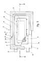
- Fig. 1 ein elektrisches Heizgerät gemäß der vorliegenden Erfindung in einer geschnittenen Seitenansicht längs der Linie I-I aus Fig. 2;
- Fig. 2 das elektrische Heizgerät aus Fig. 1 in einer geschnittenen Rückansicht längs der Linie 11-11 aus Fig. 1;
- Fig. 3 in einer Ansicht längs des Pfeiles 111 aus Fig. 1 die innere Wärmeform des elektrischen Heizgerätes gemäß Fig. 1; und
- Fig. 4 eine geschnittene Explosionsdarstellung längs der Linie IV-IV aus Fig. 3.
- 1 shows an electric heater according to the present invention in a sectional side view along the line II of Fig. 2.
- FIG. 2 shows the electric heater from FIG. 1 in a sectional rear view along the line 11-11 from FIG. 1;
- FIG. 3 shows the internal heat form of the electrical heating device according to FIG. 1 in a view along arrow 111 from FIG. 1; and
- 4 shows a sectional exploded view along the line IV-IV from FIG. 3.
In Fig. 1 ist in einer geschnittenen Seitenansicht ein elektrisches Heizgerät 10 gemäß der vorliegenden Erfindung dargestellt. Das Heizgerät 10 umfaßt ein elektrisch isolierendes aber thermisch leitfähiges Gehäuses 11, das z. B. aus Industriekeramik oder aus einem entsprechenden Kunststoff gefertigt ist. In dem Gehäuse 11 ist als kompakte Einheit eine von dem Gehäuse 11 unabhängige innere Wärmeform 12 angeordnet, die über ein Versorgungskabel 13 mit Strom versorgt wird. Das Versorgungskabel 13 gelangt über einen z. B. mit Silikon abgedichteten Durchlaß 14 in das Innere des Gehäuses 11, wo es mit der inneren Wärmeform 12 verbunden ist.1 shows an
Die Wärmeform 12 ist eine Art Steckvorrichtung 15, die aus einem Träger 16 und einem Gegenstück 17 besteht, die längs einer Trennlinie 18 voneinander trennbar sind. Diese Steckvorrichtung 15 ist vorzugsweise aus einem wärmeleitenden aber hochgradig temperaturresistenten Kunststoff gefertigt.The
Unten über die Steckvorrichtung 15 steht ein erhabener Bereich 19 über, über den in noch zu beschreibender Weise ein in dem Inneren der Wärmeform 12 vorhandenes Heizelement in wärmeleitender Verbindung mit dem Gehäuse 11 steht.A raised
Das Gehäuse 11 ist z. B. über einen aus Übersichtlichkeitsgründen nicht dargestellten Deckel oben so abgeschlossen, daß es als Tauchform 20 z. B. zur Heizung in ein Aquarium oder ein Fußbad eingebracht werden kann.The
In dem Inneren des Gehäuses 11 ist eine Aufnahme 21 für Klemmittel 22 in Form einer in Fig. 2 gezeigten Biegefeder 23 vorgesehen. Diese Biegefeder 23 drückt in der gezeigten Darstellung die Steckvorrichtung 15 in Fig. 2 so nach unten, daß der erhabene Bereich 19 in guten wärmeleitenden Kontakt mit der Innenseite des Gehäuses 11 gelangt. Wie in Fig. 2 bei 24 angedeutet, ist die Steckvorrichtung 15 in dem Gehäuse 11 mittels eines Vergußmaterials 24 vergossen, das ein Kunststoff, Silikon, kalt vergießbare Keramik oder ein beliebiger anderer Gießstoff sein kann, der zwar wärmeleitend aber elektrisch isolierend ist. Auf diese Weise ist die innere Wärmeform 12 über den erhabenen Bereich 19 sowie das Vergußmaterial 24 in gutem wärmeleitendem Kontakt mit dem Inneren des Gehäuses 11, so daß die Wärme aus dem Inneren der Steckvorrichtung 15 ohne große Übergangsverluste über die Außenfläche 25 des Gehäuses 11 an die Umgebung abgegeben werden kann. Durch Verwendung von Wärmeleitpaste kann der Wärmeübergang noch verbessert werden.A
Fig. 3 zeigt eine Draufsicht auf die Wärmeform 12 aus den Figuren 1 und 2, wobei Bereiche der Steckvorrichtung 15 zur besseren Übersichtlichkeit weggebrochen sind.FIG. 3 shows a top view of the
In dem Inneren der Steckvorrichtung 15 sind ein unteres, elektrisch leitendes Blech 27 mit einer Anschlußfahne 28 sowie ein oberes, elektrisch leitendes Blech 31 mit einer Anschlußfahne 32 eingeklemmt. Die Anschlußfahnen 28 und 32 sind sowohl seitlich als auch in der Höhe zueinander versetzt, wie sich dies aus einem Vergleich der Figuren 1 und 3 ergibt.In the interior of the plug-in
Zwischen dem oberen Blech 27 und dem unteren Blech 31 ist ein Heizelement 33 aus Heizkeramik (Kaltleiter; PTC-Element) eingespannt, durch das über das Versorgungskabel 13, die Anschlußfahnen 28 und 32 sowie die Bleche 27 und 31 ein elektrischer Strom geleitet wird. Das Heizelement weist einen großen positiven Temperaturkoeffizienten auf und ermöglicht so eine durch die Nennansprechtemperatur vorgegebene Einstellung auf eine vorgegebene Temperatur, ohne daß es zu einer Überhitzung oder eine Überstromaufnahme führt, wie dies in der Beschreibungseinleitung bereits ausführlich erörtert wurde. Wird das Heizgerät z. B. als Tauchsieder verwendet, kann die Nennansprechtemperatur z. B. 120°C betragen. Wenn das zu erhitzende Wasser durch Unachtsamkeit verdampft, der Tauchsieder also "trocken läuft", kommt es hier nicht zu Überhitzungen oder hoher Stromaufnahme, für die Sicherheit ist also gesorgt. Um eine geringere Temperatur als die Nennansprechtemperatur einzustellen, ist es lediglich erforderlich, die Stärke des fließenden Stromes zu reduzieren.A
Das obere Blech 31 weist den erhabenen Bereich 19 auf, der an seiner Unterseite in wärmeleitendem Kontakt mit dem Heizelement 33 ist. Mit seiner Oberseite 34 wirkt der erhabene Bereich 19 als Wärmekontaktfläche 35, über die die in dem Heizelement 33 entstehende Wärme über Wärmeleitung nach außen abgegeben wird.The
Auch das untere Blech 27 weist eine Erhebung 36 auf, auf welcher das Heizelement 33 angeordnet ist. Diese Erhebung 36 greift mit dem daraufliegenden Heizelement 33 so von unten in die der Erhebung 19 entsprechende Vertiefung ein, daß ein Aufnahmeraum 37 für das Heizelement 33 gebildet wird, wie dies in der seitlichen Schnittdarstellung der Fig. 4 deutlicher zu erkennen ist. In diesem Aufnahmeraum 37 ist das Heizelement 33 unverlierbar aufgenommen.The
In der Explosionsdarstellung der Fig. 4 ist die Steckvorrichtung 15 so auseinandergezogen, daß das Gegenstück 17 links von Blechen 27, 31 sowie Heizelement 33 angeordnet ist und sich der selbsttragende Träger 16, der teilweise gebrochen ist, rechts davon befindet. Es ist zu erkennen, daß in dem Gegenstück 17 Nuten 38 und 39 zur Führung der Bleche 27 bzw. 31 vorgesehen sind. Der Abstand der Nuten 38 und 39, die übrigens auch in dem selbststragenden Träger 16 vorhanden sind, ist so gewählt, daß die mit dazwischen aufgenommenem Heizelement 33 in die Nuten 38, 39 eingeschobenen Bleche 27, 31 so zusammengepreßt werden, daß ein sehr guter Wärmeübergang von dem Heizelement 33 zu den erhabenen Bereichen 19 und 36 erfolgt. Über diese erhabenen Bereiche 19 und 36 erfolgt gleichfalls die Stromzufuhr bzw. Abfuhr. Die Nuten 38 und 39 laufen übrigens sowohl im Gegenstück 17 als auch im Träger 16 U-förmig um, so daß die Bleche 27, 31 und das zwischen ihnen aufgenommene Heizelement 33 bei zusammengeschobener Steckvorrichtung 15 unverlierbar in dieser aufgenommen sind. Am Träger 16 und am Gegenstück 17 sind Rastnasen 40a und 40b vorgesehen, so daß die zusammengeschobene Steckvorrichtung 15 fest verrastet ist.4, the plug-in
In Fig. 4 ist ferner zu erkennen, daß in dem Gegenstück 17 eine Durchgangsöffnung 41 für die Anschlußfahne 32 vorgesehen ist. Auch für die Anschlußfahne 28 ist eine derartige Durchgangsöffnung vorgesehen, wegen der Lage des Schnittes in Fig. 4 dort jedoch nicht zu erkennen.In Fig. 4 it can also be seen that a through
Abschließend sei noch erwähnt, daß der Träger 16 und das Gegenstück 17 eine von dem Gehäuse 11 unabhängige Klemmvorrichtung 42 bilden, welche die Bleche 27 und 31 gegen das Heizelement 33 preßt.Finally, it should also be mentioned that the
Aus Fig. 4 ist zu erkennen, daß der Abstand der Bleche 27 und 31 zueinander im Bereich außerhalb der topfartigen Erhebungen 19 und 36 größer ist als die Dicke des Heizelements 33, was durch die gewählte Abkantung der Bleche 27 und 31 erreicht wird. Um für eine gute Isolation zwischen den Blechen 27 und 31 zu sorgen, kann zwischen diesen außerhalb des Heizelementes 33 ein Isolierstoff 43 vorgesehen sein, wie dies in Fig. 4 links von dem Heizelement 33 angedeutet ist.From Fig. 4 it can be seen that the distance between the
Abschließend sei noch auf einen in Fig. 1 schematisch angedeuteten und wahlweise verwendeten Temperaturregler 45 hingewiesen, der zur Temperaturregelung verwendet werden kann, wenn eine tiefere Temperatur gewünscht wird, als sie durch die Nennansprechtemperatur der PTC-Heizelemente vorgegeben ist. Der Temperaturregler 45 wirkt im einfachsten Falle als ein über einen Stellknopf 46 einstellbarer Strombegrenzer, der den durch die Heizelemente fließenden Strom in Abhängigkeit von der Stellung des Stellknopfes 46 begrenzt und so die Aufheizung der Heizelemente auf unterhalb der Nennansprechtemperatur einstellt.Finally, reference is made to a
Claims (9)
Applications Claiming Priority (2)
| Application Number | Priority Date | Filing Date | Title |
|---|---|---|---|
| DE4405040A DE4405040C2 (en) | 1994-02-17 | 1994-02-17 | Electric heater |
| DE4405040 | 1994-02-17 |
Publications (3)
| Publication Number | Publication Date |
|---|---|
| EP0668710A2 true EP0668710A2 (en) | 1995-08-23 |
| EP0668710A3 EP0668710A3 (en) | 1996-03-27 |
| EP0668710B1 EP0668710B1 (en) | 2001-09-26 |
Family
ID=6510467
Family Applications (1)
| Application Number | Title | Priority Date | Filing Date |
|---|---|---|---|
| EP94120383A Expired - Lifetime EP0668710B1 (en) | 1994-02-17 | 1994-12-22 | Electric heating apparatus |
Country Status (6)
| Country | Link |
|---|---|
| US (1) | US5633978A (en) |
| EP (1) | EP0668710B1 (en) |
| AT (1) | ATE206272T1 (en) |
| DE (2) | DE4405040C2 (en) |
| ES (1) | ES2164079T3 (en) |
| PT (1) | PT668710E (en) |
Families Citing this family (8)
| Publication number | Priority date | Publication date | Assignee | Title |
|---|---|---|---|---|
| ITVI940068A1 (en) * | 1994-05-11 | 1994-08-11 | Hydor Srl | IMMERSION COMPACT HEATER, ESPECIALLY FOR AQUARIUMS. |
| US5828810A (en) * | 1996-04-26 | 1998-10-27 | Nine Lives, Inc. | Positive temperature coefficient bar shaped immersion heater |
| US6054692A (en) * | 1997-06-25 | 2000-04-25 | Takehiko Hitomi | Heating device, heat storing type heat generating body and protective sheet for the heating device |
| US20050180078A1 (en) * | 2004-02-13 | 2005-08-18 | Adams Rite Aerospace, Inc. | Solenoid protection method and apparatus |
| US8388318B2 (en) * | 2009-04-06 | 2013-03-05 | Bristol Compressors International, Inc. | Hermetic crankcase heater |
| GB201001999D0 (en) * | 2010-02-08 | 2010-03-24 | Haven Ltd | Frost protection system for condensate drain pipe |
| DE102017103039B3 (en) | 2017-02-15 | 2018-06-07 | Eichenauer Heizelemente Gmbh & Co. Kg | Heating unit for heating liquids in a motor vehicle |
| DE102018218667A1 (en) * | 2018-10-31 | 2020-04-30 | Mahle International Gmbh | PTC heating module and a method for manufacturing the PTC heating module |
Citations (5)
| Publication number | Priority date | Publication date | Assignee | Title |
|---|---|---|---|---|
| DE2806159A1 (en) * | 1978-02-14 | 1979-08-16 | Siemens Ag | DIVERSEER |
| US4480174A (en) * | 1981-09-11 | 1984-10-30 | Acra Electric Corporation | Thermostatically controlled electric compressor sump heater having self-contained thermostat |
| DD257534A1 (en) * | 1987-02-06 | 1988-06-15 | Elektrogeraete Ingbuero Veb | ELECTRIC RESISTANCE HEATING ELEMENT |
| US4822980A (en) * | 1987-05-04 | 1989-04-18 | Gte Products Corporation | PTC heater device |
| FR2634090A1 (en) * | 1988-07-07 | 1990-01-12 | Diry Andre | Device for heating up a flow of liquid, especially water or diesel fuel |
Family Cites Families (9)
| Publication number | Priority date | Publication date | Assignee | Title |
|---|---|---|---|---|
| DE257534C (en) * | 1912-01-17 | |||
| NL7504083A (en) * | 1975-04-07 | 1976-10-11 | Philips Nv | SELF-REGULATING HEATING ELEMENT. |
| US4091267A (en) * | 1976-07-19 | 1978-05-23 | Texas Instruments Incorporated | Self-regulating electric heater |
| ATE5122T1 (en) * | 1979-09-28 | 1983-11-15 | Siemens Aktiengesellschaft | HEATING DEVICE WITH PTC thermistor HEATING ELEMENT. |
| DE2948593C2 (en) * | 1979-12-03 | 1987-05-07 | Fritz Eichenauer GmbH & Co KG, 6744 Kandel | Electric resistance heating element |
| DE2948592C2 (en) * | 1979-12-03 | 1990-05-10 | Fritz Eichenauer GmbH & Co KG, 6744 Kandel | Electric resistance heating element |
| DE3136094A1 (en) * | 1980-09-19 | 1982-05-06 | Gte Products Corp., Wilmington, Del. | "SUBMERSIBLE HEATING DEVICE" |
| DE3048452C2 (en) * | 1980-12-22 | 1983-08-25 | Kabelwerke Reinshagen Gmbh, 5600 Wuppertal | Electric heater |
| JP2532502Y2 (en) * | 1991-02-20 | 1997-04-16 | 株式会社村田製作所 | Heating unit |
-
1994
- 1994-02-17 DE DE4405040A patent/DE4405040C2/en not_active Expired - Fee Related
- 1994-12-22 ES ES94120383T patent/ES2164079T3/en not_active Expired - Lifetime
- 1994-12-22 EP EP94120383A patent/EP0668710B1/en not_active Expired - Lifetime
- 1994-12-22 PT PT94120383T patent/PT668710E/en unknown
- 1994-12-22 DE DE59409877T patent/DE59409877D1/en not_active Expired - Fee Related
- 1994-12-22 AT AT94120383T patent/ATE206272T1/en not_active IP Right Cessation
-
1995
- 1995-02-16 US US08/389,896 patent/US5633978A/en not_active Expired - Fee Related
Patent Citations (5)
| Publication number | Priority date | Publication date | Assignee | Title |
|---|---|---|---|---|
| DE2806159A1 (en) * | 1978-02-14 | 1979-08-16 | Siemens Ag | DIVERSEER |
| US4480174A (en) * | 1981-09-11 | 1984-10-30 | Acra Electric Corporation | Thermostatically controlled electric compressor sump heater having self-contained thermostat |
| DD257534A1 (en) * | 1987-02-06 | 1988-06-15 | Elektrogeraete Ingbuero Veb | ELECTRIC RESISTANCE HEATING ELEMENT |
| US4822980A (en) * | 1987-05-04 | 1989-04-18 | Gte Products Corporation | PTC heater device |
| FR2634090A1 (en) * | 1988-07-07 | 1990-01-12 | Diry Andre | Device for heating up a flow of liquid, especially water or diesel fuel |
Also Published As
| Publication number | Publication date |
|---|---|
| ATE206272T1 (en) | 2001-10-15 |
| US5633978A (en) | 1997-05-27 |
| DE4405040C2 (en) | 1997-09-25 |
| DE59409877D1 (en) | 2001-10-31 |
| ES2164079T3 (en) | 2002-02-16 |
| PT668710E (en) | 2002-03-28 |
| DE4405040A1 (en) | 1995-08-24 |
| EP0668710B1 (en) | 2001-09-26 |
| EP0668710A3 (en) | 1996-03-27 |
Similar Documents
| Publication | Publication Date | Title |
|---|---|---|
| EP0017057B1 (en) | Fuel oil preheating device | |
| AT390137B (en) | ELECTRIC COOKER | |
| DE2614433B2 (en) | Self-regulating heating element | |
| DE2255736C3 (en) | Electric heater | |
| DE3325310A1 (en) | DEVICE FOR PRODUCING MOLDED PARTS | |
| EP0696429B1 (en) | Electrical warming device | |
| EP0544244A2 (en) | Temperature - detector | |
| EP0757210A1 (en) | Radiating cooker element | |
| EP0668710B1 (en) | Electric heating apparatus | |
| DE3201367A1 (en) | Electrical resistance heater comprising PTC resistance elements | |
| DE9318886U1 (en) | Temperature control unit for infusion solutions | |
| EP0028356A1 (en) | Temperature indicator for showing the temperature condition of a ceramic cooking surface | |
| DE2617701A1 (en) | HEATING DOOR | |
| WO1986002712A1 (en) | Heat storage elements | |
| DE2343833A1 (en) | Electric hot-plate - has a glass-like or ceramic plate with at least one heater below it pressed to the plate | |
| DE4105845C1 (en) | ||
| DE2219319A1 (en) | ELECTRIC HEATER | |
| DE69513514T2 (en) | COMPACT SUBMERSIBLE RADIATOR, ESPECIALLY FOR AQUARIUMS | |
| CH677053A5 (en) | ||
| DE3122750A1 (en) | "LAMP" | |
| DE2459649B2 (en) | Electric hotplate with a heating system consisting of three heating elements | |
| EP1249671A2 (en) | Electric convection heater | |
| EP0513953B1 (en) | Thermostat-valve | |
| DE3112676C2 (en) | ||
| DE3506759C1 (en) | Self-regulating electrical heating body |
Legal Events
| Date | Code | Title | Description |
|---|---|---|---|
| PUAI | Public reference made under article 153(3) epc to a published international application that has entered the european phase |
Free format text: ORIGINAL CODE: 0009012 |
|
| AK | Designated contracting states |
Kind code of ref document: A2 Designated state(s): AT BE CH DE ES FR GB IT LI NL PT |
|
| PUAL | Search report despatched |
Free format text: ORIGINAL CODE: 0009013 |
|
| AK | Designated contracting states |
Kind code of ref document: A3 Designated state(s): AT BE CH DE ES FR GB IT LI NL PT |
|
| 17P | Request for examination filed |
Effective date: 19960413 |
|
| RAP1 | Party data changed (applicant data changed or rights of an application transferred) |
Owner name: HOFSAESS, MARCEL |
|
| 17Q | First examination report despatched |
Effective date: 20000105 |
|
| GRAG | Despatch of communication of intention to grant |
Free format text: ORIGINAL CODE: EPIDOS AGRA |
|
| 17Q | First examination report despatched |
Effective date: 20001128 |
|
| GRAG | Despatch of communication of intention to grant |
Free format text: ORIGINAL CODE: EPIDOS AGRA |
|
| GRAG | Despatch of communication of intention to grant |
Free format text: ORIGINAL CODE: EPIDOS AGRA |
|
| GRAH | Despatch of communication of intention to grant a patent |
Free format text: ORIGINAL CODE: EPIDOS IGRA |
|
| GRAH | Despatch of communication of intention to grant a patent |
Free format text: ORIGINAL CODE: EPIDOS IGRA |
|
| GRAA | (expected) grant |
Free format text: ORIGINAL CODE: 0009210 |
|
| AK | Designated contracting states |
Kind code of ref document: B1 Designated state(s): AT BE CH DE ES FR GB IT LI NL PT |
|
| REF | Corresponds to: |
Ref document number: 206272 Country of ref document: AT Date of ref document: 20011015 Kind code of ref document: T |
|
| REG | Reference to a national code |
Ref country code: CH Ref legal event code: NV Representative=s name: TROESCH SCHEIDEGGER WERNER AG Ref country code: CH Ref legal event code: EP |
|
| REF | Corresponds to: |
Ref document number: 59409877 Country of ref document: DE Date of ref document: 20011031 |
|
| REG | Reference to a national code |
Ref country code: GB Ref legal event code: IF02 |
|
| GBT | Gb: translation of ep patent filed (gb section 77(6)(a)/1977) |
Effective date: 20011214 |
|
| ET | Fr: translation filed | ||
| REG | Reference to a national code |
Ref country code: ES Ref legal event code: FG2A Ref document number: 2164079 Country of ref document: ES Kind code of ref document: T3 |
|
| REG | Reference to a national code |
Ref country code: PT Ref legal event code: SC4A Free format text: AVAILABILITY OF NATIONAL TRANSLATION Effective date: 20011210 |
|
| PLBE | No opposition filed within time limit |
Free format text: ORIGINAL CODE: 0009261 |
|
| STAA | Information on the status of an ep patent application or granted ep patent |
Free format text: STATUS: NO OPPOSITION FILED WITHIN TIME LIMIT |
|
| 26N | No opposition filed | ||
| PGFP | Annual fee paid to national office [announced via postgrant information from national office to epo] |
Ref country code: PT Payment date: 20051124 Year of fee payment: 12 |
|
| PGFP | Annual fee paid to national office [announced via postgrant information from national office to epo] |
Ref country code: NL Payment date: 20051214 Year of fee payment: 12 |
|
| PGFP | Annual fee paid to national office [announced via postgrant information from national office to epo] |
Ref country code: ES Payment date: 20051215 Year of fee payment: 12 Ref country code: CH Payment date: 20051215 Year of fee payment: 12 |
|
| PGFP | Annual fee paid to national office [announced via postgrant information from national office to epo] |
Ref country code: FR Payment date: 20051219 Year of fee payment: 12 |
|
| PGFP | Annual fee paid to national office [announced via postgrant information from national office to epo] |
Ref country code: AT Payment date: 20051220 Year of fee payment: 12 |
|
| PGFP | Annual fee paid to national office [announced via postgrant information from national office to epo] |
Ref country code: GB Payment date: 20051222 Year of fee payment: 12 |
|
| PGFP | Annual fee paid to national office [announced via postgrant information from national office to epo] |
Ref country code: BE Payment date: 20060116 Year of fee payment: 12 |
|
| PG25 | Lapsed in a contracting state [announced via postgrant information from national office to epo] |
Ref country code: LI Free format text: LAPSE BECAUSE OF NON-PAYMENT OF DUE FEES Effective date: 20061231 Ref country code: CH Free format text: LAPSE BECAUSE OF NON-PAYMENT OF DUE FEES Effective date: 20061231 Ref country code: BE Free format text: LAPSE BECAUSE OF NON-PAYMENT OF DUE FEES Effective date: 20061231 |
|
| PGFP | Annual fee paid to national office [announced via postgrant information from national office to epo] |
Ref country code: IT Payment date: 20061231 Year of fee payment: 13 |
|
| PG25 | Lapsed in a contracting state [announced via postgrant information from national office to epo] |
Ref country code: PT Free format text: LAPSE BECAUSE OF NON-PAYMENT OF DUE FEES Effective date: 20070622 |
|
| PG25 | Lapsed in a contracting state [announced via postgrant information from national office to epo] |
Ref country code: NL Free format text: LAPSE BECAUSE OF NON-PAYMENT OF DUE FEES Effective date: 20070701 |
|
| REG | Reference to a national code |
Ref country code: PT Ref legal event code: MM4A Free format text: LAPSE DUE TO NON-PAYMENT OF FEES Effective date: 20070622 |
|
| REG | Reference to a national code |
Ref country code: CH Ref legal event code: PL |
|
| GBPC | Gb: european patent ceased through non-payment of renewal fee |
Effective date: 20061222 |
|
| NLV4 | Nl: lapsed or anulled due to non-payment of the annual fee |
Effective date: 20070701 |
|
| REG | Reference to a national code |
Ref country code: FR Ref legal event code: ST Effective date: 20070831 |
|
| PG25 | Lapsed in a contracting state [announced via postgrant information from national office to epo] |
Ref country code: GB Free format text: LAPSE BECAUSE OF NON-PAYMENT OF DUE FEES Effective date: 20061222 Ref country code: AT Free format text: LAPSE BECAUSE OF NON-PAYMENT OF DUE FEES Effective date: 20061222 |
|
| BERE | Be: lapsed |
Owner name: *HOFSASS MARCEL Effective date: 20061231 |
|
| REG | Reference to a national code |
Ref country code: ES Ref legal event code: FD2A Effective date: 20061223 |
|
| PG25 | Lapsed in a contracting state [announced via postgrant information from national office to epo] |
Ref country code: FR Free format text: LAPSE BECAUSE OF NON-PAYMENT OF DUE FEES Effective date: 20070102 Ref country code: ES Free format text: LAPSE BECAUSE OF NON-PAYMENT OF DUE FEES Effective date: 20061223 |
|
| PGFP | Annual fee paid to national office [announced via postgrant information from national office to epo] |
Ref country code: DE Payment date: 20090127 Year of fee payment: 15 |
|
| PG25 | Lapsed in a contracting state [announced via postgrant information from national office to epo] |
Ref country code: IT Free format text: LAPSE BECAUSE OF NON-PAYMENT OF DUE FEES Effective date: 20071222 |
|
| PG25 | Lapsed in a contracting state [announced via postgrant information from national office to epo] |
Ref country code: DE Free format text: LAPSE BECAUSE OF NON-PAYMENT OF DUE FEES Effective date: 20100701 |