EP0668708A2 - Drehbares Gehause für Heizelement - Google Patents
Drehbares Gehause für Heizelement Download PDFInfo
- Publication number
- EP0668708A2 EP0668708A2 EP95630013A EP95630013A EP0668708A2 EP 0668708 A2 EP0668708 A2 EP 0668708A2 EP 95630013 A EP95630013 A EP 95630013A EP 95630013 A EP95630013 A EP 95630013A EP 0668708 A2 EP0668708 A2 EP 0668708A2
- Authority
- EP
- European Patent Office
- Prior art keywords
- base
- housing
- baseplate
- heater
- ring
- Prior art date
- Legal status (The legal status is an assumption and is not a legal conclusion. Google has not performed a legal analysis and makes no representation as to the accuracy of the status listed.)
- Withdrawn
Links
Images
Classifications
-
- F—MECHANICAL ENGINEERING; LIGHTING; HEATING; WEAPONS; BLASTING
- F24—HEATING; RANGES; VENTILATING
- F24C—DOMESTIC STOVES OR RANGES ; DETAILS OF DOMESTIC STOVES OR RANGES, OF GENERAL APPLICATION
- F24C7/00—Stoves or ranges heated by electric energy
- F24C7/04—Stoves or ranges heated by electric energy with heat radiated directly from the heating element
-
- H—ELECTRICITY
- H05—ELECTRIC TECHNIQUES NOT OTHERWISE PROVIDED FOR
- H05B—ELECTRIC HEATING; ELECTRIC LIGHT SOURCES NOT OTHERWISE PROVIDED FOR; CIRCUIT ARRANGEMENTS FOR ELECTRIC LIGHT SOURCES, IN GENERAL
- H05B3/00—Ohmic-resistance heating
- H05B3/02—Details
- H05B3/04—Waterproof or air-tight seals for heaters
-
- H—ELECTRICITY
- H05—ELECTRIC TECHNIQUES NOT OTHERWISE PROVIDED FOR
- H05B—ELECTRIC HEATING; ELECTRIC LIGHT SOURCES NOT OTHERWISE PROVIDED FOR; CIRCUIT ARRANGEMENTS FOR ELECTRIC LIGHT SOURCES, IN GENERAL
- H05B3/00—Ohmic-resistance heating
- H05B3/78—Heating arrangements specially adapted for immersion heating
Definitions
- This invention relates to electric heaters such as immersion heaters and, more particularly, to a housing for use with such heaters.
- a housing for use with an immersion heater the provision of such a housing providing a base for mounting a screwplug assembly including a heating element and a thermostat; the provision of such a housing which is readily rotatable through 360° to facilitate connection of electrical conductors to the screwplug assembly; the provision of such a housing which is particularly useful with screwplug assemblies installed in out-of-the-way, hard to reach places thus to enable quick and easy installation connection and disconnection of the conduit; the provision of such a housing having a cover readily removable for both conduit connection and assembly repair or replacement; the provision of such a housing which provides protection from electrical shock to those working in the vicinity of the heater and who may come into contact with the housing; the provision of such a housing which is available in different sizes for use with different size heater assemblies; and, the provision of such a housing which is a low cost, easy to manufacture unit.
- a housing is for use with an electrical heater that mounts on the sidewall of a container.
- the heater heats a fluid in the container.
- a heating element is installed in a fitting, and the housing facilitates connection of an electrical conductor to the heater regardless of its location.
- a base of the housing has an opening in which the fitting is received. The base is positioned against the sidewall when the heater is installed.
- a cover of the housing is sized to fit over the base and attaches to the base. The cover has an opening therein through which the electrical conductor is routed for connection to an outer end of the heating element.
- a ring is used as a platform for the housing base to rotate on. Three (3) screws are used to capture the base under the screw heads and clamp it to the fitting.
- the base is freely rotatable with respect to the fitting. Rotation of the base positions the cover so the conduit opening is readily accessible to an installer thereby to facilitate connection of the conduit to the heating element regardless of the heater location.
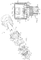
- an electric immersion heater I includes a heating element H.
- the heating element is a generally U-shaped heating rod R (see Fig. 5) with the respective ends of the rods extending through a fitting F.
- Fitting F comprises a screwplug P having a threaded end which is screwed into a correspondingly threaded opening O in the sidewall S of a container C.
- the outer ends of the rod project through the outer end of the screwplug. These ends are adapted for connection of electrical conductors E by which electricity is routed to the heating element.
- the resulting I2r loss in rod R produces heat used to heat a liquid L stored in the container.
- housing 10 first includes a base 12.
- the base first includes a circular base plate 14.
- a concentric opening 16 is formed in the base plate, the diameter of the opening being greater than the diameter of the screwplug.
- the screwplug has a flange X which, as shown in Fig. 4, is hexagonal shaped.
- the diameter of flange X is slightly larger than diameter of opening 16.
- the flange keeps the screwplug from being withdrawn. It will be noted that there are gaps between the side of the opening and the portion of the opening covered by the flange. In order to cover these gaps a ring 26 is used between the screw plug flange and the base.
- base 12 in addition to the base plate 14 has an outwardly extending tongue 18.
- This tongue is generally rectangular in shape, and when the housing is being assembled, the tongue is turned at right angles to the base plate. The tongue then extends upwardly.
- a circular knock-out 20 is formed in the tongue. This knock-out, when removed leaves an opening 22 for routing the electrical conductors E into the housing.
- the housing is freely rotatable to align opening 22 with the direction from which the conductors are routed to the heater. This not only greatly simplifies heater installation, but reduces the force on the conductors which otherwise is present if they have to be installed at an angle to their direction of routing.
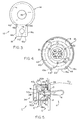
- Housing 10 includes a mounting means 24 for attaching the screwplug to the base.
- the ring 26 is located on the outside of base plate 14 between the base plate and screw plug flange.
- the ring has an inner diameter which is smaller than that of opening 16 in base plate 14, but slightly larger than the diameter of the heating element cluster in the screwplug. Further, the outer diameter of the ring is greater than the diameter of opening 16 and the corners of the screwplug flange hex.
- ring 26 has three holes 28 equidistantly spaced about its circumference. Each hole is also equidistantly spaced from the center of the ring.
- the radius R from the center of ring 26 to the holes is such that when the ring is in place, and properly aligned, the holes fit over the gaps between flange X and the sidewall of opening 16.
- Mounting means 24 further includes fasteners, in the form of screws or bolts 32, for clamping (under the screw heads) the ring and base to the screw plug flange.
- the fasteners shown in the drawings are, for example, 10-32 type F Phillips head screws. It will be understood, however, that other type screws or bolts could be used.
- holes corresponding to those in the ring are formed in the flange, and would be threaded.
- the ring and flange would all be turned until the respective sets of holes aligned and then the screws 32 would fit through the ring and the screw heads clamp against the base as the screws are tightened into the screwplug flange.
- Heater housing 10 next includes a cover 36 which is similar in construction to that described in co-pending patent application Serial No. 08/002,183. That is, cover 36 is cup or cap shaped having a face plate 38 and a circumferential sidewall 40. As shown in Fig. 4, the outer margin of base plate 14 is formed so that it can be upwardly turned, in the same direction as tongue 18, to form a lip 42 which extends substantially about base 12. The diameter of cover 36 corresponds to that of the base plate, after lip 42 is formed, so the sidewall of cover 36 fits over the lip. The sidewall also has a cutout 44 which is sized to fit over tongue 18 when the cover is set in place. As shown in Fig.
- tongue 18 has a center section 18a, and respective side sections 18b, 18c on either side of the center section.
- Sides 18b, 18c are folded back from section 18a when base 12 is formed, and cutout 44 is sized to fit over section 18a.
- Each side section 18b, 18c has a threaded hole 46 for receiving a screw 48.
- Sidewall 40 of cover 36 has keyways 50 formed on either side of cutout 44. The keyways extend upward from the base of the sidewall and are located so the upper end of respective keyways align with the screwholes 46.
- the screws 48 are threaded into holes 46 through the respective keyways 50. As the screws are tightened, they press the bottom of the cover sidewall against the lip to complete the heater housing assembly.
- the screwplug is first installed on the base using the ring, as above described so flange X of the screwplug is on the inside of the base plate and ring.
- the screws 32 are inserted through the holes in ring 26.
- the screws are sufficiently tightened so base plate, ring and screwplug are lightly pulled together.
- cover 36 is not installed, and base 12 is freely rotatable.
- the threaded outer end of the screwplug is threaded into the opening O in sidewall S of the fluid container.
- the base of housing 10 is rotated until opening 22 in tongue 18 is oriented in the direction from which the electrical conductors E are routed to the heater.
- the screws 32 are tightened until base plate is locked together with the ring and screwplug.
- the ends of the electrical conductors are inserted through opening 22 and are attached to terminals T on the ends of heater rod R to electrically connect the heater rod to a power source.
- cover 36 is set in place and tightening of screws 48 lock the cover and base of the housing together.
- thermostat M it is desirable to install a thermostat M with the heater assembly.
- one side of the electrical circuit to rod R is routed through the thermostat. If the thermostat senses that the fluid temperature is too high, it breaks the electrical circuit to the rod and subsequently restores it when the fluid temperature falls below a level to which the thermostat is set.
- thermostat M is located above the inner end of the screwplug (as shown in Fig. 2), or rearwardly of it (as shown in Fig. 5).
- Cover 36 can be of a height which simply allows it to fit over the inner end of the screwplug, or it can be of a height which accommodates installation of the thermostat.
- Bracket 52 is generally hat-shaped having two base legs 52a, 52b which abut the inner face of base plate 14 for attachment of the bracket to the base plate, by spot welding for example.
- the length of these base legs is such that when the outer end of the legs are aligned with the outer margin of the base plate 14, the inner end of the leg, from which a center section 52c of the bracket extends upwardly (as shown in Fig. 1), does not meet or contact the outer edge of screwplug flange X.
- Section 52b is sufficiently long so when the thermostat is installed on it, it does not interfere with the electrical terminals protruding inwardly from the inner end of the screwplug.
- Thermostat M is attached to the bracket in any convenient manner.
- the case of the thermostat is spot welded to the bracket leg 52c, or the case has a pocket in which the bracket leg fits, or the leg has a screw hole (54) through which a screw is inserted into a corresponding threaded opening in the thermostat.
- the housing provides a base for mounting a screwplug assembly which includes a heating element and a thermostat.
- the housing readily rotates through 360° to facilitate connection of electrical conductors to the screwplug assembly, this being particularly useful when screwplug assemblies are installed in out-of-the-way, hard to reach places.
- a housing cover is readily removable for both conduit connection and assembly repair or replacement, and facilitates quick and easy installation connection and disconnection of a conduit.
- the housing provides protection from electrical shock to those working in the vicinity of a heater and those who may come into contact with the housing.
- the housing is available in different sizes for use with different size heater assemblies, and the housing is a low cost, easy to manufacture unit.
Landscapes
- Engineering & Computer Science (AREA)
- Chemical & Material Sciences (AREA)
- Combustion & Propulsion (AREA)
- Mechanical Engineering (AREA)
- General Engineering & Computer Science (AREA)
- Resistance Heating (AREA)
- Heat-Pump Type And Storage Water Heaters (AREA)
Applications Claiming Priority (2)
| Application Number | Priority Date | Filing Date | Title |
|---|---|---|---|
| US08/197,251 US5528722A (en) | 1994-02-16 | 1994-02-16 | Rotatable housing for screen plug immersion heater |
| US197251 | 1994-02-16 |
Publications (2)
| Publication Number | Publication Date |
|---|---|
| EP0668708A2 true EP0668708A2 (de) | 1995-08-23 |
| EP0668708A3 EP0668708A3 (de) | 1996-02-14 |
Family
ID=22728640
Family Applications (1)
| Application Number | Title | Priority Date | Filing Date |
|---|---|---|---|
| EP95630013A Withdrawn EP0668708A3 (de) | 1994-02-16 | 1995-02-16 | Drehbares Gehause für Heizelement. |
Country Status (8)
| Country | Link |
|---|---|
| US (1) | US5528722A (de) |
| EP (1) | EP0668708A3 (de) |
| JP (1) | JPH07302679A (de) |
| KR (1) | KR950033275A (de) |
| CN (1) | CN1112222A (de) |
| AU (1) | AU1228995A (de) |
| CA (1) | CA2141083C (de) |
| TW (1) | TW392379B (de) |
Families Citing this family (8)
| Publication number | Priority date | Publication date | Assignee | Title |
|---|---|---|---|---|
| KR100229140B1 (ko) * | 1997-03-26 | 1999-11-01 | 윤종용 | 전자렌지의 램프 전원공급장치 |
| KR100233431B1 (ko) * | 1997-04-10 | 1999-12-01 | 윤종용 | 전자렌지의 쵸크회로기판 보호장치 |
| KR100492314B1 (ko) * | 2002-12-06 | 2005-06-02 | 삼성전자주식회사 | 히터의 전원 연결구조 |
| CN104390327B (zh) * | 2014-10-24 | 2017-03-29 | 珠海格力电器股份有限公司 | 三相ptc加热器支架及空调器 |
| US10064519B2 (en) * | 2014-12-02 | 2018-09-04 | Hula Dog Franchise, Inc. | Spike-style toasting device |
| CN106642659A (zh) * | 2016-11-03 | 2017-05-10 | 江阴市国豪电热电器制造有限公司 | 一种方便拆卸的管套式电加热器 |
| CN108541091B (zh) * | 2018-06-11 | 2019-09-24 | 如皋天安电气科技有限公司 | 一种复合绝缘电热管 |
| CN109846445A (zh) * | 2019-03-18 | 2019-06-07 | 深圳英美达医疗技术有限公司 | 一种双模探头3d扫描装置 |
Family Cites Families (9)
| Publication number | Priority date | Publication date | Assignee | Title |
|---|---|---|---|---|
| US1742638A (en) * | 1928-01-11 | 1930-01-07 | Joseph H Simon | Electric heater and thermostatic control therefor |
| GB325140A (en) * | 1929-03-13 | 1930-02-13 | British Brass Fittings Ltd | Improvements in or relating to electric immersion heaters |
| GB638512A (en) * | 1946-03-23 | 1950-06-07 | Blaw Knox Co | Improvements in or relating to electric immersion heaters |
| US2810815A (en) * | 1954-02-19 | 1957-10-22 | Wiegand Co Edwin L | Electric heaters |
| DE1150187B (de) * | 1957-08-31 | 1963-06-12 | Margret Stiebel Geb Schueddeko | Heizflansch fuer duennwandige Behaelter |
| US3450860A (en) * | 1966-03-28 | 1969-06-17 | Kneisley Electronic Co | Liquid heater with high temperature safety control |
| US4394562A (en) * | 1981-06-11 | 1983-07-19 | Industrial Engineering And Equipment Incorporated | Electric immersion heater mounting flange |
| DE8805986U1 (de) * | 1988-04-16 | 1988-08-11 | Röckert, Leo, 8501 Schwarzenbruck | Anschlußkopf mit Tauchrohr |
| US5191634A (en) * | 1991-01-11 | 1993-03-02 | Wellman Thermal Systems Corporation | Screw plug immersion heater comprising separate header and threaded sleeve sections |
-
1994
- 1994-02-16 US US08/197,251 patent/US5528722A/en not_active Expired - Lifetime
-
1995
- 1995-01-25 CA CA002141083A patent/CA2141083C/en not_active Expired - Lifetime
- 1995-02-15 KR KR1019950002795A patent/KR950033275A/ko not_active Withdrawn
- 1995-02-16 EP EP95630013A patent/EP0668708A3/de not_active Withdrawn
- 1995-02-16 JP JP7051882A patent/JPH07302679A/ja active Pending
- 1995-02-16 CN CN95102101A patent/CN1112222A/zh active Pending
- 1995-02-16 AU AU12289/95A patent/AU1228995A/en not_active Abandoned
- 1995-04-22 TW TW084103977A patent/TW392379B/zh active
Also Published As
| Publication number | Publication date |
|---|---|
| KR950033275A (ko) | 1995-12-22 |
| CA2141083A1 (en) | 1995-08-17 |
| JPH07302679A (ja) | 1995-11-14 |
| EP0668708A3 (de) | 1996-02-14 |
| TW392379B (en) | 2000-06-01 |
| AU1228995A (en) | 1995-08-24 |
| CN1112222A (zh) | 1995-11-22 |
| CA2141083C (en) | 1998-05-26 |
| US5528722A (en) | 1996-06-18 |
Similar Documents
| Publication | Publication Date | Title |
|---|---|---|
| US4543007A (en) | Adjustable luminaire support knuckle | |
| CA1296077C (en) | Light fixture connector | |
| US4643511A (en) | Auxiliary wire connections for side post batteries | |
| US5331231A (en) | Rectifier device for three-phase generators in vehicles | |
| CA2141083C (en) | Rotatable heater housing | |
| EP0717196A2 (de) | Adapter für geneigte Decken | |
| US11165205B2 (en) | Multi-phase connector for electric powertrain system | |
| CA1095159A (en) | Busway plug assembly | |
| US5173057A (en) | Permanent protective cover | |
| KR100691916B1 (ko) | 전기장치의 접지시스템 | |
| US7165980B2 (en) | Conduit bushing with revolving lug | |
| EP0370825A2 (de) | Elektrische Kontakteinheit für Leuchten | |
| US4575178A (en) | Connector for securing wires to a battery terminal | |
| JPH05251887A (ja) | ケーブル貫通案内装置 | |
| US4312558A (en) | Flush mounted plug | |
| US3795891A (en) | Battery terminal | |
| US4668034A (en) | Grounding clamp for electrical duplex receptacle mounted in a metal outlet box | |
| US6220901B1 (en) | Electric motor terminal board assembly | |
| US4314738A (en) | Auxiliary equipment enclosure unit for watthour meter sockets | |
| JP2570618B2 (ja) | 屋外用通信装置の構造 | |
| US5239278A (en) | Transformer and mounting bracket assembly | |
| GB2131631A (en) | Terminal blockscrew-contact adaptors | |
| CN219913245U (zh) | 空调器的室内机以及空调器 | |
| CA1187954A (en) | Adjustable insulator attachment for isolated phase bus switch | |
| EP0889556A2 (de) | Schalttafelmontierbarer Anschlussblock |
Legal Events
| Date | Code | Title | Description |
|---|---|---|---|
| PUAI | Public reference made under article 153(3) epc to a published international application that has entered the european phase |
Free format text: ORIGINAL CODE: 0009012 |
|
| AK | Designated contracting states |
Kind code of ref document: A2 Designated state(s): AT BE CH DE DK ES FR GB GR IT LI LU NL PT SE |
|
| PUAL | Search report despatched |
Free format text: ORIGINAL CODE: 0009013 |
|
| AK | Designated contracting states |
Kind code of ref document: A3 Designated state(s): AT BE CH DE DK ES FR GB GR IT LI LU NL PT SE |
|
| 17P | Request for examination filed |
Effective date: 19960814 |
|
| STAA | Information on the status of an ep patent application or granted ep patent |
Free format text: STATUS: THE APPLICATION HAS BEEN WITHDRAWN |
|
| 18W | Application withdrawn |
Withdrawal date: 19980504 |