EP0668643B1 - Hochspannungsschalter mit kugelförmiger Entladungsstrecke, Hochspannungspulsgeneratorkreis und Verfahren zur Schaltung mit Hochspannungsentladung - Google Patents
Hochspannungsschalter mit kugelförmiger Entladungsstrecke, Hochspannungspulsgeneratorkreis und Verfahren zur Schaltung mit Hochspannungsentladung Download PDFInfo
- Publication number
- EP0668643B1 EP0668643B1 EP95300965A EP95300965A EP0668643B1 EP 0668643 B1 EP0668643 B1 EP 0668643B1 EP 95300965 A EP95300965 A EP 95300965A EP 95300965 A EP95300965 A EP 95300965A EP 0668643 B1 EP0668643 B1 EP 0668643B1
- Authority
- EP
- European Patent Office
- Prior art keywords
- sphere
- discharge
- gap
- high voltage
- electrodes
- Prior art date
- Legal status (The legal status is an assumption and is not a legal conclusion. Google has not performed a legal analysis and makes no representation as to the accuracy of the status listed.)
- Expired - Lifetime
Links
Images



Classifications
-
- H—ELECTRICITY
- H01—ELECTRIC ELEMENTS
- H01H—ELECTRIC SWITCHES; RELAYS; SELECTORS; EMERGENCY PROTECTIVE DEVICES
- H01H9/00—Details of switching devices, not covered by groups H01H1/00 - H01H7/00
- H01H9/14—Adaptation for built-in safety spark gaps
-
- H—ELECTRICITY
- H01—ELECTRIC ELEMENTS
- H01T—SPARK GAPS; OVERVOLTAGE ARRESTERS USING SPARK GAPS; SPARKING PLUGS; CORONA DEVICES; GENERATING IONS TO BE INTRODUCED INTO NON-ENCLOSED GASES
- H01T2/00—Spark gaps comprising auxiliary triggering means
-
- H—ELECTRICITY
- H01—ELECTRIC ELEMENTS
- H01T—SPARK GAPS; OVERVOLTAGE ARRESTERS USING SPARK GAPS; SPARKING PLUGS; CORONA DEVICES; GENERATING IONS TO BE INTRODUCED INTO NON-ENCLOSED GASES
- H01T1/00—Details of spark gaps
- H01T1/20—Means for starting arc or facilitating ignition of spark gap
- H01T1/22—Means for starting arc or facilitating ignition of spark gap by the shape or the composition of the electrodes
Definitions
- the present invention relates to switches, and in particular to high voltage sphere-gap discharge switches which operate by means of the generation of spark discharge.
- Japanese Laying-open Patent Gazette No. JP-A-63-66878 discloses a construction which employs a trigger electrode in addition to a pair of opposing electrodes, and in which a gas medium is supplied into and circulated within the discharge space.
- this construction requires an auxiliary circuit for the trigger, and the construction of the device is complicated.
- Japanese Laying-open Patent Gazette No. JP-A-58-35887 discloses a starting gap device in which a separate projection which can be extended and and retracted is attached to one of a pair of sphere electrodes.
- the voltage in this device is in the region of several hundred kilovolts and thus there is a lack of operational reproducibility, and moreover long term operation is problematical since consumption of the electrodes is high.
- One object of the present invention is to achieve stability and durability of a high voltage pulse wave-form using a simple construction.
- the discharge switch according to the present invention is a high voltage sphere-gap discharge switch which operates by means of the generation of spark discharge, comprising:
- the above mentioned air current generator it is preferable for the above mentioned air current generator to supply air to the above mentioned discharge gap at a wind speed per unit electric power of 0.5 to 25m.sec. -1 kW -1 . Furthermore, it is preferable for air to be supplied at a wind speed per unit electric power of 3 to 20m.sec. -1 kW -1 . Furthermore, it is preferable for air to be supplied at a wind speed per unit electric power of 5m.sec. -1 kW -1 or more and less than 15m.sec. -1 kW -1 .
- the above mentioned sphere electrodes prefferably be made of hollow metal. It is further preferable for there to be provided a pair of ventilation openings for generating an air current in a direction intersecting the line joining the centres of the above mentioned pair of sphere electrodes, and furthermore for an insulating case to be provided, to house the above mentioned sphere electrodes. It is furthermore preferable that the above mentioned ventilation openings be positioned such that the straight line joining their centres intersects the straight line joining the centres of the above mentioned sphere electrodes in the centre between the above mentioned sphere electrodes. It is furthermore preferable for the above mentioned ventilation opening on the air feed side to have a diameter of 1/4 to 3/4 times the outer diameter of the above mentioned sphere electrodes, and for the above mentioned ventilation opening on the air feed side.
- a discharge gap adjustment device for varying the gap between the above mentioned sphere electrodes.
- the high voltage pulse generation circuit comprises: a charge and discharge means for the temporary accumulation of electrical power for supply to a capacitive load;
- the high voltage sphere-gap discharge method according to the present invention includes a process in which air is supplied to the above mentioned discharge gap at a wind speed per unit electric power of 0.5 to 25m.sec. -1 kW -1 , by means of the above mentioned air current generator, and a process in which a high voltage is applied between the above mentioned sphere electrodes.
- the process in which the above mentioned air is supplied is a process in which the air is supplied at a wind speed per unit electric power of 3 to 20m.sec. -1 kW -1 . It is furthermore preferable for the process in which the above mentioned air is supplied to be a process in which air is supplied at a wind speed per unit electric power of 5m.sec. -1 kW -1 or more and less than 15m.sec. -1 kW -1 .
- the above mentioned projections prefferably have a projection length of 1/100 to 1/8 times the outer diameter of the above mentioned sphere electrodes and an outer diameter of 1/100 to 1/10 times the outer diameter of the sphere electrodes.
- projections are provided integrally on a pair of sphere electrodes.
- a non-uniform electric field concentrates here, and corona discharge is generated under high voltage.
- the discharge generation position and the discharge arrival position are fixed at the projections.
- the air current brought about by means of the air current generator removes ions, metal dust and the like which form on the projections. In this way the discharge path is approximately fixed, and furthermore the discharge gap environment is maintained in a constant state, and thus it is possible to stabilise the wave-form of the high voltage pulse and to increase its durability using a simple construction.
- the above mentioned action is more pronounced. Furthermore, when a pair of ventilation openings are provided to generate an air current in a direction intersecting the line joining the centres of the above mentioned pair of sphere electrodes, and an insulating case is furthermore provided to house the above mentioned sphere electrodes, the above mentioned action is more pronounced. Furthermore, when the above mentioned ventilation openings are positioned such that the straight line joining their centres intersects the straight line joining the centres of the above mentioned sphere electrodes in the centre between the above mentioned sphere electrodes, the above mentioned action is more pronounced.
- the high voltage pulse generation circuit firstly electrical power temporarily accumulates in the charge and discharge means.
- the electrical power which has accumulated in the above mentioned charge and discharge means is then supplied to the above mentioned capacitive load by the gap discharge switch discharging.
- the resonance means operates and the supplied electrical current is formed into a high voltage pulse shape.
- the method for operating a high voltage discharge switch in accordance with the present invention comprises:
- non-uniform electric fields are concentrated at the projections which are provided integrally on a pair of sphere electrodes, and the discharge generation position and the discharge arrival position are fixed at the projections. Furthermore, the air current brought about by means of the air current generator removes ions, metal dust and the like which form on the projections. In this way the discharge path is approximately fixed, and furthermore the discharge gap environment is maintained in a constant state, and thus it is possible to stabilise the wave-form of the high voltage pulse and to increase its durability using a simple construction.
- the process in which the above mentioned air is supplied is a process in which air is supplied at a wind speed per unit electric power of 3 to 20m.sec. -1 kW -1 , the above mentioned action is more pronounced. Furthermore, if the process in which the above mentioned air is supplied is a process in which air is supplied at a wind speed per unit electric power of 5m.sec. -1 kW -1 or more and less than 15m.sec. -1 kW -1 , the above mentioned action is more pronounced.
- the above mentioned projections have a projection length 1/100 to 1/8 times the outer diameter of the above mentioned sphere electrodes and an outer diameter of 1/100 to 1/10 times the outer diameter of the sphere electrodes, the above mentioned action is more pronounced.
- the gap discharge switch GS is provided with a pair of sphere electrodes 1 which are formed of a hollow metal with an outer diameter of 200 mm, for example.
- the sphere electrodes 1 may also be solid.
- the sphere electrodes 1 it is preferable for the sphere electrodes 1 to be of a lightweight hollow spherical form.
- Projections 2 are provided integrally at the facing tips of the above mentioned sphere electrodes 1.
- the sphere electrode 1 at the top of the diagram is the high voltage application side, and a high voltage terminal la is provided at the top end thereof.
- the sphere electrode 1 at the bottom of the diagram is the earth side, and an earth terminal 1b is provided at the bottom end thereof.
- the center of the sphere electrodes 1, the projections 2, and the terminals 1a and 1b are positioned on a straight line.
- the shape of the projections 2 is not particularly restricted provided that they are of a shape which projects from the spherical surface of the sphere electrodes 1. It is preferable for the shape to be cylindrical, cone-shaped, pyramid-shaped or cap-shaped, for example.
- the projection length of the projections 2 is 1/100 to 1/8 times the outer diameter of the sphere electrodes 1, and the outer diameter of the projections 2 is 1/100 to 1/10 times the outer diameter of the sphere electrodes 1.
- the two terminals 1a and 1b are rod-shaped, and they may be of either circular rod shape or angular rod shape. Neither the outer diameter nor the length of the rods are particularly limited, but it is preferable for the outer diameter of the rods to be 1/20 to 1/5 times the outer diameter of the sphere electrodes, and for the length thereof to be 3/20 to 1/2 times the diameter of the sphere electrodes, in consideration of operability of the device.
- the material of the sphere electrodes 1 should be a metal which is resistant to consumption due to repeated discharge, and the spheres are constructed from metallic elements such as stainless steel, steel or aluminum. Further, the material of the projections 2 is not particularly restricted provided it is a material which is used as an alloy for electrical contacts, and examples of such materials include those whose main components are metals selected from stainless steel, steel or tungsten, for example.
- the sphere electrodes 1 are located within an insulating case 4 which is resistant to high applied voltages.
- the sphere electrodes 1 are supported in the insulating case 4 and are enclosed therein by the terminals 1a and 1b being secured to the insulating case 4.
- the material used for the insulating case 4 is not particularly restricted provided it is an insulator, examples of which include bakelite, vinylchloride, acrylic resin and FRP.
- a pair of ventilation openings 4a and 4b are provided in the insulating case 4 in order to generate an air current in a direction perpendicular to a line joining the centers of the two electrodes 1. It is preferable for the ventilation openings 4a and 4b to be located such that the straight line joining the centers of the two ventilation openings 4a and 4b intersects the straight line joining the centers of the two sphere electrodes 1 in the center between the two sphere electrodes 1. It is preferable for the diameter of the ventilation opening 4a on the air feed side (on the left in the diagram) to be 1/4 to 3/4 times the outer diameter of the sphere electrodes 1. The diameter of the ventilation opening 4b on the exhaust side (on the right in the diagram) should be equal to or greater than that of the ventilation opening 4a.
- the ventilation opening 4a is connected to the air blowing unit of a blower 5, the rotational frequency of which can be controlled. Further, the ventilation opening 4b is open to the atmosphere.
- the blower 5 include a limit fan and a turbo fan with a relatively high static pressure.
- An exhaust device may also be used instead of the blower 5. In this case, the exhaust device is connected to the ventilation opening 4b. Examples of exhaust devices include a cyclofan with a relatively low static pressure.
- the earth terminal 1b is connected to a discharge gap adjustment device 3 which is located outside the insulating case 4.
- the adjustment device 3 can adjust the discharge gap between the projections 2 from approximately zero to a dimension approximately equal to the diameter of the sphere electrodes, by raising and lowering the earth terminal 1b.
- the adjustment device 3 is, for example, a manual jack. Further, a cylinder which is moved up and down pneumatically or hydraulically may also be used as the adjustment device 3. Furthermore, it is possible to have a construction in which both of the sphere electrodes 1 are linked to separate adjustment devices 3.
- the outer diameter of the sphere electrodes 1 and the minimum discharge gap are set by means of the adjustment device 3 such that they are approximately equal. For example, if the maximum voltage applied to the sphere electrodes 1 is approximately 175 kV and the outer diameter of the sphere electrodes 1 is 200 mm, then the discharge gap is set to 140 to 200 mm.
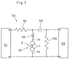
- the gap discharge switch GS is incorporated into the high voltage pulse generation circuit 50 shown in Fig. 2.
- a capacitive load 54 is connected to the output side of a direct current power supply 51 via a protection resistor 52 and a charge and discharge condenser 53 which are connected in series.
- a load resistor 56 is located in parallel with the capacitive load 54.
- the high voltage terminal 1a of the gap discharge switch GS is connected between the protection resistor 52 and the charge and discharge condenser 53, via an inductor 55.
- the earth terminal 1b of the gap discharge switch GS is connected to the capacitive load 54 and the load resistor 56.
- the spark discharge be broken instantaneously. If the spark discharge continues for a long time then the output of the direct current passed by 51 will be shorted, and the pulse generation will stop without sufficient power having been supplied. For this reason the resistance value of the protection resistor 52 must be of a value which is sufficiently large to keep the current at or below the rated current value even if the short circuit continues, and in this way the power supply 51 is protected.
- the spark discharge path tends to be difficult to break when the wind speed of the supplied air is low.
- the peak of the pulse wave is lowered, the pulse repetition frequency is increased and it is difficult to obtain a spark discharge after the voltage has been sufficiently increased.
- stable control is impossible and in pronounced cases breaking of the circuit is impossible.
- the wind speed of the supplied air is greater than is necessary, the peak of the pulse wave is sufficiently high, but an adequate pulse repetition frequency is not achieved and in extreme cases the spark discharge is not generated.
- the wind speed of the supplied air it is preferable for the wind speed of the supplied air to be in the range 0.5 to 25 m.sec. -1 kW -1 .
- the air is more preferable for the air to be supplied at a wind speed of 3 to 20 m.sec. -1 kW -1 .
- the wind speed of the supplied air and the discharge gap have a large effect on the pulse wave peak and the pulse repetition frequency. Over an extended period it is not possible to obtain a high voltage pulse in which a stable pulse wave peak and pulse repetition frequency are maintained, merely by adjusting the discharge gap.
- the high voltage sphere-gap discharge switch GS In order to control the high voltage sphere-gap discharge switch GS in a stable condition it is necessary for the air which removes ions and metal dust and the like, generated at the projections 2, to be supplied appropriately.
- the high voltage pulse generation circuit 50 which employs the high voltage sphere-gap discharge switch GS can produce a high voltage pulse continuously over a long period at low cost, it can be used in various industrial applications. For example, it can be used in a plasma generating device aimed at improving the surface of plastic.
- the width, depth and height of the insulating case 4 were all 700 mm, in order to resist high applied voltages, and a sufficient space was left between the discharge gap and the insulating case 4.
- the discharge gap GAP was 150 mm
- the diameter of the ventilation opening 4a was 75 mm
- the diameter of the ventilation opening 4b was 260 mm.
- the distance L from the supply opening to the center of the discharge gap was 350 mm.
- the width, depth and height of the insulating case 4 were all 700 mm, in order to resist high applied voltages, and a sufficient space was left between the discharge gap and the insulating case 4.
- the discharge gap GAP was 150 mm
- the diameter of the ventilation opening 4a was 50 mm
- the diameter of the ventilation opening 4b was 260 mm.
- the distance L from the supply opening to the center of the discharge gap was 350 mm.
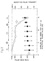
- Fig. 4 shows the experimental results obtained when the projection length of the projections 2 and the wind speed of the supplied air were varied.
- the diagonally shaded region of Fig. 4 can be regarded as the region in which switch operation due to spark discharge is performed reliably.
- the region in which the projection electrode dimension h is 8 to 20 mm and the supply wind speed is 3 to 20 m.sec. -1 kW -1 is the region in which satisfactory switch operation is possible.
- ⁇ , ⁇ and ⁇ in Fig. 4 have the same meanings as in Fig. 3.
- the discharge switch according to the present invention is provided with projections and an air current generator as outlined above, and thus the discharge path is approximately specified and the discharge gap environment is maintained in a constant state. It is thus possible to stabilize the wave-form of the high voltage pulse and to increase its durability using a simple construction.
- the above mentioned action is more pronounced. Furthermore, when a pair of ventilation openings are provided to generate an air current in a direction intersecting the line joining the centers of the above mentioned pair of sphere electrodes, and an insulating case is furthermore provided to house the above mentioned sphere electrodes, the above mentioned action is more pronounced. Furthermore, when the above mentioned ventilation openings are positioned such that the straight line joining their centers intersects the straight line joining the centers of the above mentioned sphere electrodes in the center between the above mentioned sphere electrodes, the above mentioned action is more pronounced.
- the process in which the above mentioned air is supplied is a process in which air is supplied at a wind speed of 3 to 20 m.sec. -1 kW -1 , the above mentioned action is more pronounced. Furthermore, if the process in which the above mentioned air is supplied is a process in which air is supplied at a wind speed of 5 m.sec. -1 kW -1 or more and less than 15 m.sec. -1 kW -1 , the above mentioned action is more pronounced.
- the above mentioned projections have a projection length 1/100 to 1/8 times the outer diameter of the above mentioned sphere electrodes and an outer diameter of 1/100 to 1/10 times the outer diameter of the sphere electrodes, the above mentioned action is more pronounced.
Landscapes
- Generation Of Surge Voltage And Current (AREA)
- Electrostatic Separation (AREA)
- Plasma Technology (AREA)
Claims (18)
- Hochspannungsschalter (GS) mit kugelförmiger Entladungsstrecke, der mittels der Erzeugung einer Funkenentladung arbeitet, bestehend aus:einer Stützkonstruktion (4);einem Paar kugelförmiger Elektroden (1), die an der Stützkonstruktion (4) montiert sind, einander gegenüberliegen und durch eine Entladungsstrecke voneinander getrennt sind; undeinem Luftstromgenerator (4a, 4b, 5), der mit der Stützkonstruktion (4) verbunden ist und einen Luftstrom selektiv durch die Stützkonstruktion (4) hindurch anliefert, um durch eine Funkenentladung erzeugte Produkte auszustoßen;gekennzeichnet durch
Vorsprünge (2), die an wechselseitig gegenüberliegenden Bereichen der kugelförmigen Elektroden (1) ausgebildet sind, wobei die Vorsprünge (2) eine Projektionslänge in dem Bereich von 1/100 bis 1/8 des Durchmessers der kugelförmigen Elektroden (1) und einen Außendurchmesser in dem Bereich von 1/100 bis 1/10 des Durchmessers der kugelförmigen Elektroden (1) aufweisen und der Luftstromgenerator (4a, 4b, 5) für ein Ausstoßen von Produkten der Funkenentladung von den Vorsprüngen (2) angepaßt ist. - Hochspannungsschalter mit kugelförmiger Entladungsstrecke nach Anspruch 1, bei welchem der Luftstromgenerator Luft an die Entladungsstrecke mit einer Windgeschwindigkeit je elektrischer Leistungseinheit in dem Bereich von 0.5 bis 25m·sec.

- Hochspannungsschalter mit kugelförmiger Entladungsstrecke nach Anspruch 2, bei welchem der Luftstromgenerator Luft an die Entladungsstrecke mit einer Windgeschwindigkeit je elektrischer Leistungseinheit in dem Bereich von 3 bis 20m·sec.

- Hochspannungsschalter mit kugelförmiger Entladungsstrecke nach Anspruch 3, bei welchem der Luftstromgenerator Luft an die Entladungsstrecke mit einer Windgeschwindigkeit je elektrischer Leistungseinheit von mehr als 5m·sec.


- Hochspannungsschalter mit kugelförmiger Entladungsstrecke nach einem der vorhergehenden Ansprüche, bei welchem die kugelförmigen Elektroden aus einem hohlen Metall bestehen.
- Hochspannungsschalter mit kugelförmiger Entladungsstrecke nach einem der vorhergehenden Ansprüche, bei welchem der Luftstromgenerator ein Paar Belüftungsöffnungen (4a, 4b) aufweist, die an gegenüberliegenden Seiten der Stützkonstruktion vorgesehen sind, damit ein Luftstrom in einer Richtung ermöglicht wird, die eine Linie kreuzt, welche die Mitten des Paares der kugelförmigen Elektroden verbindet, und die Stützkonstruktion ein Isoliergehäuse aufweist, welches die kugelförmigen Elektroden aufnimmt.
- Hochspannungsschalter mit kugelförmiger Entladungsstrecke nach Anspruch 6, bei welchem die Belüftungsöffnungen an gegenüberliegenden Seiten der Stützkonstruktion angeordnet sind und so miteinander fluchten, daß eine Gerade, die ihre Mitten verbindet, eine gerade Linie kreuzt, welche die Mitten der kugelförmigen Elektroden an einem Mittenpunkt zwischen den kugelförmigen Elektroden kreuzt.
- Hochspannungsschalter mit kugelförmiger Entladungsstrecke nach Anspruch 6 oder Anspruch 7, bei welchem die Belüftungsöffnung (4a) an einer Luftzuführseite einen Durchmesser in dem Bereich von 1/4 bis 3/4 des Außendurchmessers der kugelförmigen Elektroden aufweist, und die Belüftungsöffnung (4b) an einer Auslaßseite einen Durchmesser hat, der nicht kleiner ist als derjenige der Belüftungsöffnung (4a) an der Luftzuführseite.
- Hochspannungsschalter mit kugelförmiger Entladungsstrecke nach einem der vorhergehenden Ansprüche, bei welchem eine Einstellvorrichtung (3) für die Enladungsstrecke, die innerhalb der Stützkonstruktion angeordnet ist, wenigstens eine der kugelförmigen Elektroden abstützt, um den Spalt zwischen den kugelförmigen Elektroden zu verhindern.
- Schaltung zur Erzeugung eines Hochspannungsimpulses, bestehend aus:einer Ladungs- und Entladungseinrichtung (53) für die vorübergehende Ansammlung einer elektrischen Leistung zur Lieferung an eine kapazitive Last (54);einem Schalter (GS) mit einer Entladungsstrecke zur Lieferung der elektrischen Leistung, die sich in der Ladungs- und Entladungseinrichtung (53) angesammelt hat, an die kapazitive Last (54), wobei der Schalter (GS) mit einer Entladungsstrecke ein Paar kugelförmiger Elektroden (1) aufweist, die zueinander gegenüberliegend angeordnet und durch eine Entladungsstrecke voneinander getrennt sind, sowie einen Luftstromgenerator (4a, 4b, 5), der einen Luftstrom selektiv liefert, um durch eine Funkenentladung erzeugte Produkte auszustoßen; undeiner Resonanzeinrichtung (53, 55, 56) zur Lieferung der elektrischen Leistung in der Form eines Hochspannungsimpulses, wenn sie an die kapazitive Last (54) geliefert wird;gekennzeichnet durch
Vorsprünge (2), die integriert an den beiden sich gegenseitig gegenüberliegenden Bereichen der kugelförmigen Elektroden (1) vorgesehen sind, wobei die Vorsprünge (2) eine Projektionslänge in dem Bereich von 1/100 bis 1/8 des Durchmessers der kugelförmigen Elektroden (1) und einen Außendurchmesser in dem Bereich von 1/100 bis 1/10 des Durchmessers der kugelförmigen Elektroden (1) aufweisen und der Luftstromgenerator (4a, 4b, 5) für ein Ausstoßen von Produkten der Funkenentladung von den Vorsprüngen (2) angepaßt ist. - Schaltung zur Erzeugung eines Hochspannungsimpulses nach Anspruch 10, bei welcher der Schalter mit einer Entladungsstrecke einen Hochspannungsschalter mit einer kugelförmigen Entladungsstrecke gemäß einem der Ansprüche 1 bis 9 aufweist.
- Verfahren zum Betrieb eines Hochspannungs-Entladungsschalters nach Anspruch 1, wobei das Verfahren besteht aus:der Bereitstellung eines Hochspannungsschalters (GS) mit einer kugelförmigen Entladungsstrecke, bei dem ein Paar kugelförmiger Elektroden (1) zueinander gegenüberliegend angeordnet und durch eine Entladungsstrecke voneinander getrennt sind, wobei die kugelförmigen Elektroden (1) Vorsprünge (2) aufweisen, die integriert an gegenüberliegenden, wechselseitig aufeinander ausgerichteten Bereichen der kugelförmigen Elektroden (1) vorgesehen sind;der Lieferung von Luft an die Entladungsstrecke mit einer Windgeschwindigkeit je elektrischer Leistungseinheit in dem Bereich von 0.5 bis 25m/sec.kW mittels eines Luftstromgenerators (4a, 4b, 5); undder Lieferung einer Hochspannung zwischen den kugelförmigen Elektroden (1).
- Verfahren nach Anspruch 12, bei welchem der Luftstromgenerator Luft an die Entladungsstrecke mit einer Windgeschwindigkeit je elektrischer Leistungseinheit in dem Bereich von 3 bis 20m·sec.

- Verfahren nach Anspruch 13, bei welchem der Luftstromgenerator Luft an die Entladungsstrecke mit einer Windgeschwindigkeit je elektrischer Leistungseinheit von mehr als 5m/sec.kW und von weniger als 15m·sec.

- Verfahren nach einem der Ansprüche 12 bis 14, bei welchem die Vorsprünge eine Projektionslänge in dem Bereich von 1/100 bis 1/8 des Durchmessers der kugelförmigen Elektroden und einen Außendurchmesser in dem Bereich von 1/100 bis 1/10 des Durchmessers der kugelförmigen Elektroden aufweisen.
- Verfahren nach einem der Ansprüche 12 bis 15, bei welchem weiterhin die Windgeschwindigkeit der durch den Luftstromgenerator gelieferten Luft eingestellt wird.
- Verfahren nach einem der Ansprüche 12 bis 16, bei welchem weiterhin die Länge der Vorsprünge eingestellt wird.
- Verfahren nach einem der Ansprüche 12 bis 17, bei welchem weiterhin die Größe der Belüftungsöffnungen (4a, 4b) eingestellt wird, durch welche hindurch Luft angeliefert wird.
Applications Claiming Priority (2)
| Application Number | Priority Date | Filing Date | Title |
|---|---|---|---|
| JP22265/94 | 1994-02-21 | ||
| JP6022265A JP2996587B2 (ja) | 1994-02-21 | 1994-02-21 | 高電圧球ギャップ放電スイッチ、高電圧パルス発生回路及び高電圧放電スイッチング方法 |
Publications (2)
| Publication Number | Publication Date |
|---|---|
| EP0668643A1 EP0668643A1 (de) | 1995-08-23 |
| EP0668643B1 true EP0668643B1 (de) | 1997-05-07 |
Family
ID=12077946
Family Applications (1)
| Application Number | Title | Priority Date | Filing Date |
|---|---|---|---|
| EP95300965A Expired - Lifetime EP0668643B1 (de) | 1994-02-21 | 1995-02-15 | Hochspannungsschalter mit kugelförmiger Entladungsstrecke, Hochspannungspulsgeneratorkreis und Verfahren zur Schaltung mit Hochspannungsentladung |
Country Status (5)
| Country | Link |
|---|---|
| US (1) | US5587868A (de) |
| EP (1) | EP0668643B1 (de) |
| JP (1) | JP2996587B2 (de) |
| KR (1) | KR100330979B1 (de) |
| DE (1) | DE69500275T2 (de) |
Families Citing this family (8)
| Publication number | Priority date | Publication date | Assignee | Title |
|---|---|---|---|---|
| US5939841A (en) * | 1996-10-31 | 1999-08-17 | Roman; Francisco | Method and apparatus using a floating electrode to extract energy from an electric field |
| US5923130A (en) * | 1996-10-31 | 1999-07-13 | Roman; Francisco | Repetitive and constant energy impulse current generator |
| JP2000173741A (ja) | 1998-12-03 | 2000-06-23 | Nippon Paint Co Ltd | スパークギャップスイッチ及びそのスイッチング方法 |
| KR200195884Y1 (ko) * | 1999-04-09 | 2000-09-15 | 도종하 | 고압방전 실험장치 |
| CN102664352B (zh) * | 2012-05-22 | 2013-10-23 | 中国人民解放军总参谋部工程兵科研三所 | 一种可预调间隙的高电压大电流瞬态自动放电开关 |
| KR101537992B1 (ko) | 2013-11-26 | 2015-07-20 | 한국전자통신연구원 | 주파수 가변형 초고주파 펄스 발생기 |
| CN109991453A (zh) * | 2017-12-31 | 2019-07-09 | 江苏启源雷宇电气科技有限公司 | 一种可带电操作放电保护球隙 |
| CN114236326A (zh) * | 2021-11-25 | 2022-03-25 | 广西电网有限责任公司电力科学研究院 | 一种具备自动调节功能的保护球隙 |
Family Cites Families (8)
| Publication number | Priority date | Publication date | Assignee | Title |
|---|---|---|---|---|
| US1479692A (en) * | 1920-05-25 | 1924-01-01 | Balt Mfg Company | Arc gap |
| GB393752A (en) * | 1931-06-06 | 1933-06-15 | Gen Electric | Improvements in and relating to electric conversion systems |
| US3101440A (en) * | 1957-07-01 | 1963-08-20 | Meredith Publishing Company | Voltage regulator for high voltage power supplies |
| US4378511A (en) * | 1980-07-28 | 1983-03-29 | American Plasticraft Company | Tube socket assembly with corona disrupter |
| CH673357A5 (de) * | 1987-03-02 | 1990-02-28 | Bbc Brown Boveri & Cie | |
| JP2935772B2 (ja) * | 1992-06-10 | 1999-08-16 | 日本ペイント株式会社 | コロナ放電処理方法 |
| DE69313211T2 (de) * | 1992-06-10 | 1998-01-29 | Mazda Motor | Verfahren und Vorrichtung zur Coronabehandlung |
| JP2935774B2 (ja) * | 1992-06-11 | 1999-08-16 | マツダ株式会社 | コロナ放電処理装置 |
-
1994
- 1994-02-21 JP JP6022265A patent/JP2996587B2/ja not_active Expired - Fee Related
-
1995
- 1995-02-15 EP EP95300965A patent/EP0668643B1/de not_active Expired - Lifetime
- 1995-02-15 DE DE69500275T patent/DE69500275T2/de not_active Expired - Fee Related
- 1995-02-17 US US08/390,607 patent/US5587868A/en not_active Expired - Fee Related
- 1995-02-21 KR KR1019950003344A patent/KR100330979B1/ko not_active Expired - Fee Related
Also Published As
| Publication number | Publication date |
|---|---|
| JPH07235362A (ja) | 1995-09-05 |
| DE69500275D1 (de) | 1997-06-12 |
| US5587868A (en) | 1996-12-24 |
| EP0668643A1 (de) | 1995-08-23 |
| KR950034327A (ko) | 1995-12-28 |
| KR100330979B1 (ko) | 2002-12-02 |
| DE69500275T2 (de) | 1997-12-18 |
| JP2996587B2 (ja) | 2000-01-11 |
Similar Documents
| Publication | Publication Date | Title |
|---|---|---|
| JP6374582B2 (ja) | ガスイオン化装置、イオン化したガス流を生成する方法及びコロナ放電イオン化装置の中で自由電子の雲を陰イオンに変える方法 | |
| KR101415415B1 (ko) | 융삭 플라즈마 건 | |
| GB2170038A (en) | Gas laser | |
| US5587868A (en) | High voltage sphere-gap discharge switch, high voltage pulse generation circuit and high voltage discharge switching method | |
| Yahya et al. | Factors affecting the glow-to-arc transition at the cathode of an electric discharge at atmospheric pressure | |
| EP0075282B1 (de) | Gas-Laservorrichtung | |
| US6448714B1 (en) | Spark gap switch and switching method thereof | |
| US2939048A (en) | Apparatus for creating extremely high temperatures | |
| GB2099627A (en) | High voltage coaxial switch | |
| US4942337A (en) | Spark gap apparatus triggerable by microwave pulse | |
| KR100396175B1 (ko) | 절연파괴 시험용 펄스 제너레이터 | |
| KR100512651B1 (ko) | 진공 갭 스위치 | |
| Gosho et al. | Triggering of dc positive corona by pulsed UV irradiation | |
| GB2256086A (en) | Apparatus for producing pulses of charged particles. | |
| JP2002260810A (ja) | 低騒音型スパークギャップスイッチ | |
| US3531683A (en) | High energy pulse switch in which a spiral magnetic field is established around each power electrode | |
| SU792390A1 (ru) | Разр дник | |
| KANAZAWA et al. | The Effect of Electrode Shape and Arrangement on Corona Discharge in a Point-to-Plate Electrode System | |
| Fernando et al. | High-power glow discharges | |
| Anvari | The Characteristics of a 40 kV Multistage Spark Gap | |
| JPH0329316B2 (de) | ||
| Tait et al. | Breakdown characteristics of water walled arcs | |
| Abel et al. | Theoretical and experimental investigations on the plasma of a CO2 high power laser | |
| Alferov et al. | Triggered vacuum interrupter with a switching accuracy up to microsecond units | |
| JPS56129047A (en) | Electrostatic coating apparatus |
Legal Events
| Date | Code | Title | Description |
|---|---|---|---|
| PUAI | Public reference made under article 153(3) epc to a published international application that has entered the european phase |
Free format text: ORIGINAL CODE: 0009012 |
|
| AK | Designated contracting states |
Kind code of ref document: A1 Designated state(s): DE FR GB |
|
| 17P | Request for examination filed |
Effective date: 19951017 |
|
| 17Q | First examination report despatched |
Effective date: 19951113 |
|
| GRAG | Despatch of communication of intention to grant |
Free format text: ORIGINAL CODE: EPIDOS AGRA |
|
| GRAH | Despatch of communication of intention to grant a patent |
Free format text: ORIGINAL CODE: EPIDOS IGRA |
|
| GRAH | Despatch of communication of intention to grant a patent |
Free format text: ORIGINAL CODE: EPIDOS IGRA |
|
| GRAA | (expected) grant |
Free format text: ORIGINAL CODE: 0009210 |
|
| AK | Designated contracting states |
Kind code of ref document: B1 Designated state(s): DE FR GB |
|
| ET | Fr: translation filed | ||
| REF | Corresponds to: |
Ref document number: 69500275 Country of ref document: DE Date of ref document: 19970612 |
|
| PLBE | No opposition filed within time limit |
Free format text: ORIGINAL CODE: 0009261 |
|
| STAA | Information on the status of an ep patent application or granted ep patent |
Free format text: STATUS: NO OPPOSITION FILED WITHIN TIME LIMIT |
|
| 26N | No opposition filed | ||
| REG | Reference to a national code |
Ref country code: GB Ref legal event code: IF02 |
|
| PGFP | Annual fee paid to national office [announced via postgrant information from national office to epo] |
Ref country code: FR Payment date: 20040210 Year of fee payment: 10 |
|
| PGFP | Annual fee paid to national office [announced via postgrant information from national office to epo] |
Ref country code: GB Payment date: 20040211 Year of fee payment: 10 |
|
| PGFP | Annual fee paid to national office [announced via postgrant information from national office to epo] |
Ref country code: DE Payment date: 20040226 Year of fee payment: 10 |
|
| PG25 | Lapsed in a contracting state [announced via postgrant information from national office to epo] |
Ref country code: GB Free format text: LAPSE BECAUSE OF NON-PAYMENT OF DUE FEES Effective date: 20050215 |
|
| PG25 | Lapsed in a contracting state [announced via postgrant information from national office to epo] |
Ref country code: DE Free format text: LAPSE BECAUSE OF NON-PAYMENT OF DUE FEES Effective date: 20050901 |
|
| GBPC | Gb: european patent ceased through non-payment of renewal fee |
Effective date: 20050215 |
|
| PG25 | Lapsed in a contracting state [announced via postgrant information from national office to epo] |
Ref country code: FR Free format text: LAPSE BECAUSE OF NON-PAYMENT OF DUE FEES Effective date: 20051031 |
|
| REG | Reference to a national code |
Ref country code: FR Ref legal event code: ST Effective date: 20051031 |