EP0668564A1 - Resource measurement facility in a multiple operating system complex - Google Patents
Resource measurement facility in a multiple operating system complex Download PDFInfo
- Publication number
- EP0668564A1 EP0668564A1 EP94102636A EP94102636A EP0668564A1 EP 0668564 A1 EP0668564 A1 EP 0668564A1 EP 94102636 A EP94102636 A EP 94102636A EP 94102636 A EP94102636 A EP 94102636A EP 0668564 A1 EP0668564 A1 EP 0668564A1
- Authority
- EP
- European Patent Office
- Prior art keywords
- data
- operating system
- sysplex
- system images
- smf
- Prior art date
- Legal status (The legal status is an assumption and is not a legal conclusion. Google has not performed a legal analysis and makes no representation as to the accuracy of the status listed.)
- Withdrawn
Links
Images


Classifications
-
- G—PHYSICS
- G06—COMPUTING OR CALCULATING; COUNTING
- G06F—ELECTRIC DIGITAL DATA PROCESSING
- G06F11/00—Error detection; Error correction; Monitoring
- G06F11/30—Monitoring
- G06F11/34—Recording or statistical evaluation of computer activity, e.g. of down time, of input/output operation ; Recording or statistical evaluation of user activity, e.g. usability assessment
- G06F11/3466—Performance evaluation by tracing or monitoring
- G06F11/3495—Performance evaluation by tracing or monitoring for systems
-
- G—PHYSICS
- G06—COMPUTING OR CALCULATING; COUNTING
- G06F—ELECTRIC DIGITAL DATA PROCESSING
- G06F11/00—Error detection; Error correction; Monitoring
- G06F11/30—Monitoring
- G06F11/34—Recording or statistical evaluation of computer activity, e.g. of down time, of input/output operation ; Recording or statistical evaluation of user activity, e.g. usability assessment
- G06F11/3466—Performance evaluation by tracing or monitoring
- G06F11/3476—Data logging
Definitions
- the invention relates to a sysplex with a plurality of operating system images connected through connections comprising a reporter facility for reporting data from the sysplex.
- the reporter facility has in-storage buffers and data sets in the operating system images containing the reportable data.
- the IBM Corporation currently offers a sysplex in which a maximum of eight MVS images are connected together using the MVS Cross System Coupling Facility. This is described in the article "Use of XCF to facilitate Communication among Independent Processes", IBM Technical Disclosure Bulletin, vol. 3, no. 11, April 1991, pp. 357-359.
- By adding to the number of operating system images one can ensure that the sysplex is continuously available since the impact of planned system outages or system failures is either eliminated or restricted to a small group of end users.
- the performance of a sysplex with a larger number of operating system images is improved and indeed allows for incremental growth - as a user needs more computing power, he or she needs to only add a further image rather than upgrading the whole of the installation.
- RMF Resource Measurement Facility
- US-A-5 119 493 (Janis et al) teaches a method for maintaining a selective document history log within a data processing system having multiple resource objects which are accessible by a plurality of users within the system.
- the history log is created and associated with each resource object for which documentation of selected activities is desired.
- a list of activities is created and is utilized to filter all activities which take place with respect to a particular resource object. Using this method it is possible to record only those activities which are of interest and thus memory space is efficiently used.
- US-A-5 109 486 (Seymour) teaches a requesting manager which send a message to its local configuration processor requesting notices of status changed in a general or particular resource or node.
- the configuration manager establishes a record in its status monitoring file containing the information from the requesting processes' messages. From this information, the performance of the system may be analyzed.
- WO-A-93/00632 (ICL Data AB) teaches a method and system for monitoring and changing the operation of a computer system consisting of a plurality of computers connected in the form of a local area network.
- the system includes at least one event report generator in each executable program whose execution should be monitored, an event processing machine for processing events which are reported by an event report generator.
- An interface is provided for transferring an event reported by an event report generator to an event processing machine. From this machine information relating to the performance of the system may be obtained.
- a first data server in a first one of the operating system images one or more second data servers in the operating system images with the in-storage buffers or data sets containing reportable data, whereby when the sysplex is in operation the second data servers on receipt of a request collect the reportable data from the data sets and pass it through the connections to the first data server which then passes it to the reporter facility.
- the reporter facility can have two types of data sets in each operating system image and the requests to collect the reportable data indicate in which one of the data sets the reportable data is present.
- the reporter facility includes an answer area created by the first data server into which the reportable data is stored. This allows the efficient recovery of the reportable data when it is to be processed. Storing the data on an external medium, for example, would slow down the processing of the data by a reporter processor.
- the reporter facility finds particular application in a monitoring facility for monitoring the resources in a sysplex in which the data sets include data relating to the use and load of resources within the sysplex.
- the invention also comprises a method for reporting data in a sysplex with a plurality of operating system images comprising the following steps: a first step of sending from a first one of the operating system images a request for the reportable data to other ones of the operating system images, a second step of collecting the reportable data in the other ones of the operating system images, a third step of returning the reportable data to the first one of the operating system images, a fourth step of storing the reportable data in an answer area created in the first one of the operating system images.
- the method has the following steps: a first step of sending from a first one of the operating system images a request with search criteria for establishing in which ones of the operating system images the reportable data is present, a second step of matching the search criteria with the reportable data in the operating system images, a third step of returning an image list of operating system images in which the reportable data is present to the first one of the operating system images, a fourth step of using the image list for sending to the operating system images a request for collecting the reportable data in the operating system images, a fifth step of returning the reportable data to the first one of the operating system images, a sixth step of storing the reportable data in an answer area created in the first one of the operating system images.
- the use of the reporter facility is not confined to an application within a resource monitoring facility. It can also find application in any sysplex in which data has to be collected and collated by one of the operating system images from the other ones of the operating system images.
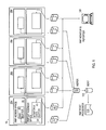
- Fig. 1 shows an overview of a sysplex 10 containing a measurement facility.
- the sysplex 10 has a plurality of operating system images 20a, 20b, 20c, 20d.
- FIG. 1 only four operating system images are shown for clarity. More images may be added and, in the preferred embodiment, thirty-two images are present. Reference signs on the Fig. 1 are also provided only for one of the images 20a. This is also for clarity, the corresponding elements in the other images 20b, 20c and 20d perform the same functions as those in the image 20a.
- Each of the images 20 has an address space in which are placed application programs (not shown) or parts of application programs and a first measurement facility address space 30, termed the RMF address space, and a second measurement facility address space 50, termed the RMFGAT address space.
- the preferred embodiment of the invention has two measurement facility address spaces 30, 50. It would be possible to incorporate the functions present in both the first measurement facility address space 30 and the second measurement facility address space 50 into a single measurement facility address space.
- a first plurality of in-storage buffers 40 termed SMF data.
- SMF data The functioning of these in-storage buffers 40 will be explained in more detail below.
- a second plurality of in-storage buffers 60 termed Monitor III data
- the second plurality of in-storage buffers 60 stores the so-called Monitor III records which allow the continuous monitoring of system data and allow the solution of temporary performance problems.
- Monitor III data The role of the second plurality of in-storage buffers 60 will be explained in more detail below.
- the first plurality of in-storage buffers 40 and the second plurality of in-storage buffers 60 can be stored in memory from whence they may be passed to the measurement facility address spaces in other images as will be explained later.
- a first data set 70 is connected to the first measurement facility address space 30 and a second data set 80 is connected to the second measurement facility address space 50.
- the SMF data is passed to both the first in-storage buffer 40 and the first data set 70 at the same time if both are present.
- the Monitor III data is passed to both the second in-storage buffer 60 and the second data set 80 at the same time if both are present.
- the data sets 70, 80 and in-storage buffers 40, 60 are collectively referred to as data groups.
- the sysplex 10 incorporates two analysis programs for evaluating the data stored in either of the first in-storage buffer 40 or the second in-storage buffer 60.
- a measurement facility processor 110 (the RMF Post Processor) collects the data from the direct access storage devices 70, merges it onto a single storage device 90 and sorts it as required. The sorted data is also stored on a storage device 100. Although the storage devices 90 and 100 are shown as two single storage devices in Fig. 1, in practice they are two different areas of the same storage device.
- the measurement facility processor 110 uses the merged and sorted data to display information about the performance of the sysplex 10.
- the measurement facility reporter 120 collects the data from the direct access storage devices 80 and allows a real time analysis of the performance of the sysplex 10.
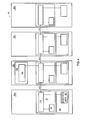
- Fig. 2A shows an overview of the first measurement facility address space 30 with the first plurality of in-storage buffer 40.
- the first plurality of in-storage buffers 40 stores the so-called system management facilities (SMF) records which allow an analysis of the long term system workload and resource utilisation.
- SMF system management facilities
- the SMF data gathering routines 32 obtain information about the system and passes this information to the first in-storage buffers 40 and the first data set 70.
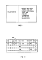
- Fig. 3a shows an example of the format of SMF data records 310 as the stored in the first plurality of data sets 40.
- the SMF data record 310 consists of an SMF record header 320 which is in this case eighteen or twenty-four bytes long and information 330 which can be up to 32756 bytes in length. The exact length of the SMF record 310 is indicated in the SMF record header 320 as will be described later.
- the structure of the information 330 is variable and is specified by the user of the SMF records 310.
- the fixed structure of the SMF record header 320 is shown in Fig. 3B.
- the first field in the SMF record header 320 is called SMFxLEN and is two bytes in length. It indicates the total length of the SMF record 310 including the SMF record header 320 and the information parts 330 of the SMF record 310.
- the next field is called SMFxSEG and is used if the SMF data spans more than one SMF record 310, i.e. if the data that is to be recorded is more than 32,756 bytes in length. If the SMF data does not span more than one SMF record 310, then the two bytes in the SMFxSEG field are both set to hexadecimal zero.
- the SMFxLEN and the SMFxSEG fields together form a four byte record descriptor called the record descriptor word (RDW).
- the next field in the SMF record 310 is the SMFxFLG which indicates the operating system in which the SMF records were generated. It is one byte in length. For example, if the byte is set to 3, it indicates an MVS/SP Version 4 operating system. If set to 4, it indicates that the operating system is MVS/ESA and if set to 5 that the operating system is MVS/XA. The values 0, 1 and 2 are reserved for other purposes.
- the SMFxRTY field is one byte in length and can take the values 0 to FF (hexadecimal). It indicates the type of SMF record 310 being generated.
- the record types 0 to 127 are reserved for use by the IBM operating system images.
- record types 70-79 are used by the resource measurement facility as described herein.
- the record types 128-255 are free for use by applications programs.
- the SMFxTME field is four bytes in length and indicates the time elapsed since midnight in hundredths of a second since the SMF record 310 was created.
- the SMFxDTE field is also four bytes in length and indicates the date on which the SMF record 310 was created.
- the SMFxSID field indicates the identification number of the system or of the operating system image 20 on which the SMF record 310 was created.
- SMFxSSI subsystem identification
- SMFxSTY subtype of the record
- x indicates the type of SMF record.
- X can take a value from 0 to 255. In the preferred embodiment of the invention, x has a value between 70 and 79.
- SMF data gathering routines 32 are supplied on each image 20. These SMF data gathering routines 32 pass the information which the owner of the system has specified in the form of records to buffers 35 and thence fill each of the data sets 40 one at a time. When one of the data sets 40 becomes full, the SMF data gathering routines 32 search for an empty data set within the first measurement facility address space 30. Whilst one data set is being filled with SMF records, the SMF dump routines 45 are used to write the data out of the full ones of the first plurality of data sets 40 onto the storage space reserved on the direct access storage device 70.
- the structure of the second measurement facility address space 50 is shown in Fig. 2B. It includes not only the second plurality of in-storage buffers 60 mentioned above but also a data gatherer 55 which collects the system data, formats it into samples and stores the data in the in-storage buffers 60 or data sets 80.
- the data gatherer 55 is started by a command which has the following options:
- the suboptions control the saving of the data from the
- the data gatherer 55 combines all samples gathered into a set of samples which can then be summarised and reported by the measurement facility reporter 120.
- the exact structure of the set of samples depends on the type of data collected.
- Fig. 4 shows an overview of the sysplex 10 with a sysplex data server 170.
- the reference signs used in Fig. 4 refer to the same elements of the sysplex 10 as those used in Fig. 1.
- a sysplex data server 170 is provided within the first measurement facility address space 30 in addition to the modules shown in Fig. 1, a sysplex data server 170 is provided.
- the sysplex data server 170 has access as is shown on Fig. 4 to the SMF record data stored in the buffers 35 shown in Fig. 2A and also to the buffers 60 provided in the second measurement facility address space 50 as shown in Fig. 2B.
- the sysplex data server 170 is identical in each of the operating system images 20a-d and is joined through connections 410 shown on Fig. 4 to all of the other sysplex data servers 170 in the other operating system images 20a-d.
- the sysplex data server 170 is always active in the first measurement facility address space 50 when the resource measurement facility is running in the operating system image 20.
- the sysplex data server 170 is able to process all types of data which is used by the resource measurement facility, in particular it is able to use the SMF data and the Monitor III data. It supplies a series of General Use Programming Interface (GUPI) services which may be invoked either by the RMF reporter sessions themselves, e.g. the measurement facility reporter 120, or by authorised applications programs.
- GUI General Use Programming Interface
- Fig. 4 also shows a user address space 150 in the operating system image 20b which is connected to the sysplex data server 170 in the first measurement facility address space of the operating system image.
- the user address space 150 incorporates an applications program 160 which is authorized to use the GUPI services provided by the sysplex data server 170.
- the sysplex data server 170 provides the following GUPls:
- the ERBDSQRY GUPI is used to request a directory of SMF record data available in the data sets 40 or sets of samples in the data sets 60 on each operating system image 20 in the sysplex 10.
- the CALL statement for ERBDSQRY is written as shown in Fig. 5A.
- the parameters supplied to the ERBDSQRY have the following values:
- the sysplex data server 170 Specifies the address in the memory where the sysplex data server 170 returns the requested information.
- the area can be either in the user address space 150 or in a public address and data space.
- the parameter answer area addr is defined as a pointer variable of length 4.
- the parameter answer_area_alet is defined as an unsigned integer variable of length 4.
- the answer area length is defined as an unsigned integer variable of length 4.
- ERBDSQRY function code Specifies the ERBDSQRY function code and may take one of the following values: SMF
- Request information about SMF records 310 of any RMF type and subtype will be returned about all SMF records 310 where the projected RMF measurement interval end time (specified in the RMF product section) is contained in the time interval specified in the start time and end time parameters (see below).
- the request type parameter is defined as a character variable of length 3.
- the start_time parameter is defined as a character variable of length 14 and is presented in the so-called "sorted" format:
- the parameter end time is defined as character variable of length 14 in the same "sorted" format as the start time parameter.
- the informa tion may be omitted by passing a value of
- the parameter's value will then default to the "newest" SMF time found in any of the data sets 40 at the time the ERBDSQRY GUPI service is called.
- the smf_record_type_info parameter is defined as a character variable of length 7.
- Fig. 5B Specifies the list of SMF record types for which information is requested. As shown in Fig. 5B it is defined as an unsigned integer variable of length 4 that specifies the number of elements in an array, followed by an array of pairs of unsigned integers of length 2, in which the first number of each pair specifies the record type and the second number of each pair specifies the record subtype. For record types without subtypes, a subtype of 0 is specified.
- the parameter can take one of the following values:
- the smf_system_name_info parameter is defined as a character variable of length 7.
- the smf_system_name_list is defined as an unsigned integer variable of length 4 that specifies the number of array elements, followed by an array of character of length 4. Each array element has an image name.
- the return_code parameter contains the return code for the GUPI. It is defined as an unsigned integer variable of length 4.
- the reason code contains the reason code why the operation was not carried out successfully. It is defined as an unsigned integer variable of length 4.
- an answer area 600 is created at the address in memory specified by the answer_area_addr parameter.
- the structure of this answer area 600 is divided into a header area 601 and a data area 603.
- the header area 601 is common to all three GUPls and is shown in Fig. 6A.
- the data area is different depending on the type of GUPI called and, in the case of the ERBDSQRY GUPI, the value of the request type parameter.
- Fig. 6B shows the data area 603 for the answer area when the request_type parameter has the value SMF.
- Fig. 6C shows the data area 603 for the answer area 600 when the request type parameter has the value RMF.
- the data areas 603 contain a system list entry for the data gathered from each operating system image 20.
- the data section 603 returned when the ERBDSQRY GUPI is completed has a layout shown in Fig. 6B when the request_type parameter's value is SMF.
- the blocks in Fig. 6B contain the following information:
- Fig. 6C the data section 603 of the answer area 600 when the request type parameter has the value RMF.
- the fields RECTOKn 650 and SMFHDRn 320, 652 contain the same information as in Fig. 6B.
- the RMFINFO field 655 contains 32 bytes of additional information from the RMF product section of the SMF record 310.
- Fig. 6D shows the additional information which is contained in the RMF product section of the SMF record 310. It contains the following fields: SMFxxDAT which has a length of 4 bytes and give actual start time of the RMF interval.
- SMFxxlST which has a length of 4 bytes and gives the actual start time of the RMF interval.
- SMFxxlNT which has a length of 4 bytes and gives the actual length of the RMF interval.
- SMFxxOIL which has a length of 2 bytes and gives the projected interval length in seconds.
- SMFxxSYN which has a length of 2 bytes and gives the RMF synchronization value in seconds.
- SMFxxLGO which has a length of 8 bytes and gives the offset time between Greenwich Mean Time (GMT) and local time.
- SMFxxGIE which has a length of 8 bytes and gives the projected end in GMT of the RMF interval end.
- the ERBDSREC GUPI is used to request SMF record data from the data sets 40 on each operating system image 20 in the sysplex 10. For each requested SMF record, the record token 650 included in the answer area 600, obtained from an earlier call of the ERBDSQRY GUPI, is included on the list of record tokens 650 passed as parameters to the ERBDSREC GUPI.
- the area can be in the user address space 150 or in a public address and data space.
- the parameter is defined as a pointer variable of length 4.
- the parameter answer_area_alet is defined as an unsigned integer variable of length 4.
- the answer area length is defined as an unsigned integer variable of length 4.
- the return_code parameter contains the return code for the GUPI. It is defined as an unsigned integer variable of length 4.
- the reason code contains the reason code why the operation was not carried out successfully. It is defined as an unsigned integer variable of length 4.
- the answer area consists of the common header 601 described in Fig. 6A and a data section 800.
- the structure of the data section 800 is shown in Fig. 8.
- the answer area 800 contains a data section header 810 plus a data section entry 850 for each requested SMF record.
- the entries 850 appear in the order of the request, i.e. the order of tokens specified in the rmf_record_token_list parameter.
- the data entries 850 for each SMF record 310 contain a data section header 810 provided by the ERBDSREC GUPI and the SMF record (SMFRECORDn) 850 itself.
- the various fields in the data section 800 have the following values:
- the ERB3XDRS GUPI is used to request a set-of-samples of Monitor III data according to a specified date and time range.
- the parameters supplied to the ERB3XDRS have the following values:
- the sysplex data server 170 Specifies the address of an answer area in the memory where the sysplex data server 170 returns the requested information.
- the area can be either in the user address space 150 or in a public address and data space.
- the parameter answer_area_addr is defined as a pointer variable of length 4.
- the parameter answer_area_alet is defined as an unsigned integer variable of length 4.
- the answer_area_length is defined as an unsigned integer variable of length 4.
- This parameter specifies the date and time of the beginning of the time range information which is requested.
- the start time parameter is defined as a character variable of length 14 in the "sorted" format as explained above.
- This parameter specifies the date and time of the end of the time for which range information is requested.
- the end_time parameter is defined as character variable of length 14 in the same "sorted" format.
- SID SMF system identification
- the system name may be specified as four blanks (null value) and, as a result, information is collected from all operating system images 20 in the sysplex 10.
- the system_name parameter is defined as a character variable of length 4.
- the return_code parameter contains a return code which is defined as an unsigned integer variable of length 4.
- the reason code parameter contains a reason code which is defined as an unsigned integer variable of length 4.
- ERB3XDRS Answer Area Layout When the ERB3XDRS GUPI call returns control to the calling program and the service was completed successfully, the answer area at the address specified by the ANSWER_AREA_ADDR parameter contains the common header 601 as shown in Fig. 6A plus the requested Monitor III data section whose structure is shown in Fig. 10.
- the Monitor III data section comprises a data section header 1000 followed by the Monitor III actual data.
- the data section consists of one or more set-of-samples. The layout of the uncompressed set-of-samples is described in the incorporated by reference RMF User's Guide (IBM Manual No. GC28-1058).
- the fields in the data section header 1000 contain the following information:
- the applications program 160 running in the user address space 150 wishes to produce data about the resources of the sysplex 10.
- the applications program 160 would have interrogated the SMF data sets 40 or the monitor III data sets 60 running in the same operating system.
- the applications program 160 must therefore make use of the sysplex data server 170.
- the sysplex data server 170 is always running in the first measurement facility address space 50 when the resource measurement facility is running in the operating system image 20.
- a sysplex data server 170 must be running in the operating system image 20 in which the applications program 160 is running.
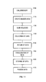
- the applications program 160 calls the ERBDSQRY service which is supplied by the sysplex data server 170 as a GUPI.
- the applications program 160 must provide to the GUPI the values of the parameters required (see above).
- the applications program 160 creates within the user address space 150 or in a public address and data space an answer area 600 for the data to be returned from ERBDSQRY service.
- the address of the created answer area 600 and its length are given in the ANSWER_AREA_ADDR, ANSWER AREA ALET and ANSWER_AREA_LENGTH parameters (step 1110).
- the applications program 160 must also supply a list of the names of the operating system images 20 from which it desires the data.
- the sysplex data server 170 must be operating on all of the named operating system images 20, otherwise an error message will be indicated by the RETURN CODE and REASON CODE parameters on return from the call.
- the applications program 160 must also specify the type of data that is to be collected. This is given by the REQUEST TYPE, START_TIME, END TIME and SMF_RECORD_TYPE_INFO parameters as described before.
- step 1120 the sysplex data facility 170 originating the called ERBDSQRY service sends requests for the data through the connections 410 to the sysplex data facilities 170 running on the operating system images 20 specified by the SMF SYSTEM NAME LIST and SMF_SYSTEM_NAME_INFO parameters.
- step 1130 the sysplex data facilities 170 interrogate the SMF data sets 40 and/or the monitor III data sets 60 running in the same operating system image 20.
- the sysplex data services 170 will return (step 1140) to the originating sysplex data facility 170 the SMF record headers 652 and, if requested, the RMF product section 655, from the SMF records 310.
- step 1150 the originating sysplex data server 170 consolidates the information and assigns a record token 650 to each of the returned SMF record headers 652.
- the common header 601 (Fig. 6A) is created for the returned information and the header, together with the returned SMF record headers 652, RMF product section records 655 and record tokens 650 are stored (step 1160) in the answer area created in step 1110.
- the structure of the data section is shown in Fig. 6B and Fig. 6C.
- the RETURN CODE and REASON CODE parameters from the ERBDSQRY GUPI are used in order to signal errors or problems arising from the ERBDSQRY GUPI, e.g. when the length of the answer area 600 assigned by the ANSWER_AREA_LENGTH parameter is smaller than that required and indicated by the LEN block 610 of the common header shown in Fig. 6A.
- the applications program 160 can now process the information stored in the created answer area 600.
- a typical use of the information would be to request SMF record data from each of the data buffers 35 on each operating system image 20.
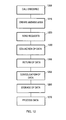
- the sysplex data server 170 is supplied with the ERBDSREC service which provides the ERBDSREC GUPI. The call of this service by the applications program 160 will now be described with the help of Fig. 12.
- step 1200 the applications program 160 calls the ERBDSREC service of the sysplex data server 170.
- the format of the ERBDSREC call is described in Fig. 7. It includes parameters (ANSWER_AREA_ADDR, ANSWER_AREA_ALET, ANSWER_AREA_LENGTH) for describing the position and length of the ERBDSREC answer area 800 which is created wither within the user address space 150 or within a public address and data space. These parameters are used in step 1210 for creating the ERBDSREC answer area 800.
- the ERBDSREC call is passed a list of record tokens 650 created by the ERBDSQRY call and stored in the ERBDSQRY answer area 600. These record tokens 650 indicate the SMF records which are requested by the applications program 160.
- step 1220 the sysplex data server 170 passes to the sysplex data servers 170 of the operating system images 20 indicated by the record tokens 650 requests for the collection of data which is carried out in step 1230.
- the step 1230 of collection of data is carried out by the sysplex data servers 170 in the operating system images 20.
- the SMF data is obtained from the first plurality of data sets 40.
- the collected SMF data is returned to the requesting sysplex data server 170 where a header is created (Fig. 6A) and the data is consolidated (step 1250) and stored (step 1260) in the answer area 800 (Fig. 8).
- the data may be subsequently processed from the answer area 800 by the applications program 160 or by another program.
- ERB3XDRS GUPI The use of the ERB3XDRS GUPI is carried out in a similar manner to that of the ERBDSREC GUPI except that Monitor III data is requested and stored in an answer area 1000 as shown on Fig. 10.
- the measurement facility processor 110 shown in Fig. 1 can run on the same operating system image 20 as the address spaces in which the answer area 800 from the ERBDSQRY call and the answer area 1000 from the ERB3XDRS call are to be found.
- the measurement facility processor 110 takes the available data and produces reports and figures based on the data thus allowing a system administrator to identify problems in the system.
- the measurement facility processor 110 produces reports about:
- the delay report (for all jobs) shows the activity of each job in the system and the hardware and software resources that are delaying each job. For all delays, the tabular form of the report also list the primary reason for the delay.
- the device delays report presents information about jobs contending for device volumes, such as direct access storage devices (DASD), tapes, or a mass storage controller (MSC) volume.
- DASD direct access storage devices
- MSC mass storage controller
- the resource-oriented device delays report presents information about the activity of input/output devices that are delaying jobs.
- Enqueue Delays The enqueue delays report presents information about jobs that are waiting to use (enqueued on) serially reusable resources. The tabular display also lists the percentage of time that enqueue contention delayed the job over the report interval and the jobs that held the resource while the delayed job was waiting.
- Enqueue Resource Delays The resource- oriented delays report presents information about serially reusable resources causing contention in the system. The tabular form of the report also lists the names of jobs that are delayed for (enqueued on) these resources, and the names of the jobs that are holding these resources.
- HSM Hierarchical Storage Manager
- JES Delays The JES delays report presents information about jobs waiting for services from JES2 or JES3. The tabular form of the report also lists explanations for the delay.
- Job Report presents information about why a job is delayed.
- the information in the report describes the primary or requested delay reason and provides possible causes leading to the job delay.
- the processor delays report presents information about all jobs delayed for or using a processor during the report interval.
- the storage delays report presents information about all jobs that used frames and the central and expanded storage working set sizes the jobs used during the report interval. If a job was delayed because of paging or swapping activity, the report also identifies the reason for the delay.
- Storage Delay Summary The storage summary report provides information on storage usage for each domain and performance group.
- the storage frames report provides information on frame counts for each address space.
- the report also provides information on the auxiliary slot count and page-in rate, including the rate of page-ins from expanded storage.
- the resource-oriented storage delays report presents information about system storage usage and paging space delay by volume serial.
- the system information report provides an overview of the sysplex 10, its workload, and the total number of jobs using resources or delayed for resources.
- the system information report can report measurements for the entire sysplex 10 and for the following group of jobs: TSO, batch, started tasks, domains, and performance groups.
- the workflow/exceptions report presents information about system activity and system resources.
- the first part of report shows the speed at which jobs move through the sysplex.
- the second part of the report shows jobs that meet the specified exception criteria.
- a graphic report can be produced to represent the workflow in speedometers.
Landscapes
- Engineering & Computer Science (AREA)
- General Engineering & Computer Science (AREA)
- Theoretical Computer Science (AREA)
- Computer Hardware Design (AREA)
- Quality & Reliability (AREA)
- Physics & Mathematics (AREA)
- General Physics & Mathematics (AREA)
- Debugging And Monitoring (AREA)
- Multi Processors (AREA)
- Information Retrieval, Db Structures And Fs Structures Therefor (AREA)
Abstract
Disclosed is a reporter facility (160) for reporting data from a sysplex with a plurality of operating system images. The reporter facility (160) comprises one or more data sets (40, 60) in the operating system images (20) contaning the reportable data. A first data server (170) is provided in a first one of the operating system images (20) and one or more second data servers (170) are provided in the operating system images (20) with the data sets (40, 60) containing reportable data. The second data servers (170) on receipt of a request issued by the first data server (170) collect the reportable data from the data sets (40, 60) and pass it through the connections (410) to the first data server (170) which then passes it to the reporter facility (160).
In one embodiment of the invention the data sets (40, 60) include data relating to the use and load of resources within the sysplex (10).
Description
- The invention relates to a sysplex with a plurality of operating system images connected through connections comprising a reporter facility for reporting data from the sysplex. The reporter facility has in-storage buffers and data sets in the operating system images containing the reportable data.
- With the ever-increasing need for computing power, a general trend is observable away from massive monolithic single-processor computers towards systems in which a large number of smaller processors are connected together and co-operate with each other in the processing of jobs. These so-called "sysplex" environments are characterised in that each of the processors within the environment runs its own operating system, i.e. each processor has its own operating system image. A central server processor provides a single synchronised timing signal across all the operating systems.
- The IBM Corporation currently offers a sysplex in which a maximum of eight MVS images are connected together using the MVS Cross System Coupling Facility. This is described in the article "Use of XCF to facilitate Communication among Independent Processes", IBM Technical Disclosure Bulletin, vol. 3, no. 11, April 1991, pp. 357-359. In the future, it is desired to increase substantially the number of operating system images. By adding to the number of operating system images, one can ensure that the sysplex is continuously available since the impact of planned system outages or system failures is either eliminated or restricted to a small group of end users. The performance of a sysplex with a larger number of operating system images is improved and indeed allows for incremental growth - as a user needs more computing power, he or she needs to only add a further image rather than upgrading the whole of the installation.
- With the increase in the number of images, a need arises to increase the systems management of the operation of the images, in particular to monitor the performance of each of the operating system images and to measure the load on the peripheral devices attached to the sysplex. By monitoring the workload of each image in the sysplex, one can ensure that the system as a whole functions in an optimal manner.
- Various prior art devices for monitoring the performance of a computer system are known. The IBM Corporation offers for MVS-based systems the so-called Resource Measurement Facility (RMF) which measures and reports on the performance and availability of a customer's system. RMF issues reports about performance problems as they occur so that installation engineers can take action on the problems before they become critical. In addition, RMF can provide information about long- term system measurements to allow the user to tune the system and to provide for more capacity if needed. General Information about RMF is to be found in IBM Manual No. GC28-1028. A user's guide for RMF is available and has the number GC28-1058. Both these publications are incorporated herein by reference.
- Similar programs are provided by Candle, Legent, Landmark and other companies.
- In the IBM Technical Disclosure Bulletin, vol 33,
No 4, September 1990, pp 79-83, a "Computer System Performance Monitor" is described which improves the capability of a computer system to monitor its own performance. The monitor offers a defined set of performance-related function which analyze the performance of the system. This is achieved either directly by the system software or by means of an optional hardware monitoring processor via a defined interface. - Whilst these programs are fine tools for monitoring the performance of single image systems, they are unable to cope with the more complicated requirements of monitoring multiple image systems such as a sysplex mentioned above.
- Known from the prior art are a number of methods for monitoring the performance of a processor in a distributed data environment. For example, the article in the IBM Technical Disclosure Bulletin, vol 34,
no 6, November 1991, pp 387-389 entitled a "Method for Workload Performance Measurement" discloses a method which provides underlying system capabilities that enable the measurement of workloads and consists of a variety and combination of user and system work activities. - The article entitled "Large System Performance Monitor" in the IBM Technical Disclosure Bulletin,
vol 24, no 3, August 1991, pp 1416-1419 teaches a monitor to analyze the activities of the system resources in order to determine and understand their utilization. The monitor described is able to do this without interfering with or degrading the performance of the system being monitored. - US-A-5 119 493 (Janis et al) teaches a method for maintaining a selective document history log within a data processing system having multiple resource objects which are accessible by a plurality of users within the system. The history log is created and associated with each resource object for which documentation of selected activities is desired. A list of activities is created and is utilized to filter all activities which take place with respect to a particular resource object. Using this method it is possible to record only those activities which are of interest and thus memory space is efficiently used.
- US-A-5 109 486 (Seymour) teaches a requesting manager which send a message to its local configuration processor requesting notices of status changed in a general or particular resource or node. The configuration manager establishes a record in its status monitoring file containing the information from the requesting processes' messages. From this information, the performance of the system may be analyzed.
- WO-A-93/00632 (ICL Data AB) teaches a method and system for monitoring and changing the operation of a computer system consisting of a plurality of computers connected in the form of a local area network. The system includes at least one event report generator in each executable program whose execution should be monitored, an event processing machine for processing events which are reported by an event report generator. An interface is provided for transferring an event reported by an event report generator to an event processing machine. From this machine information relating to the performance of the system may be obtained.
- These prior art systems all have the disadvantage that they report events to the central monitoring program every time an event occurs at the resource or in the program which is being monitored. This leads to large amounts of message traffic throughout the network which is inefficient and, more seriously, can hinder the execution of computer jobs.
- These disadvantages are solved according to the invention by a first data server in a first one of the operating system images, one or more second data servers in the operating system images with the in-storage buffers or data sets containing reportable data, whereby when the sysplex is in operation the second data servers on receipt of a request collect the reportable data from the data sets and pass it through the connections to the first data server which then passes it to the reporter facility.
- This has the advantage over the prior art that the reportable data is only passed to the first one of the operating system images when it is requested. Thus the continual data traffic is avoided and data can be requested at times at which the load on the sysplex and, in particular, on the connections between the operating system images is low. The reduction in data traffic allows a much more efficient use of the connections between the operating system images.
- The reporter facility can have two types of data sets in each operating system image and the requests to collect the reportable data indicate in which one of the data sets the reportable data is present.
- In a further embodiment of the invention, the reporter facility includes an answer area created by the first data server into which the reportable data is stored. This allows the efficient recovery of the reportable data when it is to be processed. Storing the data on an external medium, for example, would slow down the processing of the data by a reporter processor.
- The reporter facility finds particular application in a monitoring facility for monitoring the resources in a sysplex in which the data sets include data relating to the use and load of resources within the sysplex.
- By monitoring the resources of the sysplex, one is able to determine the use of and the load on the resources and, as a result, adjust the work being done by each of the resources. This is particularly important in the sysplex with multiple operating system images since the processing of a program may be held up whilst it is being executed in one of the operating system images whilst other images are standing idle.
- The invention also comprises a method for reporting data in a sysplex with a plurality of operating system images comprising the following steps: a first step of sending from a first one of the operating system images a request for the reportable data to other ones of the operating system images, a second step of collecting the reportable data in the other ones of the operating system images, a third step of returning the reportable data to the first one of the operating system images, a fourth step of storing the reportable data in an answer area created in the first one of the operating system images.
- In a further embodiment of the invention, the method has the following steps: a first step of sending from a first one of the operating system images a request with search criteria for establishing in which ones of the operating system images the reportable data is present, a second step of matching the search criteria with the reportable data in the operating system images, a third step of returning an image list of operating system images in which the reportable data is present to the first one of the operating system images, a fourth step of using the image list for sending to the operating system images a request for collecting the reportable data in the operating system images, a fifth step of returning the reportable data to the first one of the operating system images, a sixth step of storing the reportable data in an answer area created in the first one of the operating system images.
- The use of the reporter facility is not confined to an application within a resource monitoring facility. It can also find application in any sysplex in which data has to be collected and collated by one of the operating system images from the other ones of the operating system images.
-
- Fig. 1 shows an overview of the sysplex without the RMF Sysplex Data Server.
- Fig. 2A shows an overview of the first measurement facility address space (RMF Address Space).
- Fig. 2B shows an overview of the second measurement facility address space (RMFGAT Address Space).
- Fig. 3A shows an example of the format of SMF data records.
- Fig. 3B shows an example of the structure of the header for SMF data records.
- Fig. 4 shows an overview of the sysplex with the sysplex data server of the current invention.
- Fig. 5A shows the format of the CALL ERBDSQRY GUPI.
- Fig. 5B shows the format of the smf_record_type_list parameter.
- Fig. 5C shows the format of the smf_system_name_list parameter.
- Fig. 6A shows the format of the common header returned from the GUPls.
- Fig. 6B shows the answer area created by the ERBDSQRY GUPI when the request type parameter has the value SMF.
- Fig. 6C shows the answer area created by the ERBDSQRY GUPI when the request type parameter has the value RMF.
- Fig. 6D shows the format of the RMF product section of the SMF record.
- Fig. 7A shows the format of the CALL ERBDSREC GUPI.
- Fig. 7B shows the format of the rmf_record_token_list parameter.
- Fig. 8 shows the data section header answer area created on return from the ERBDSREC GUPI.
- Fig. 9 shows the format of the CALL ERB3XDRS GUPI.
- Fig. 10 shows the format of the data section header of the answer area created on return from the ERB3XDRS GUPI.
- Fig. 11 is a flow chart showing the call of the ERBDSQRY GUPI.
- Fig. 12 is a flow chart showing the call of the ERBDSREC GUPI.
- Fig. 1 shows an overview of a
sysplex 10 containing a measurement facility. Thesysplex 10 has a plurality ofoperating system images images 20a. This is also for clarity, the corresponding elements in theother images image 20a. - Each of the images 20 has an address space in which are placed application programs (not shown) or parts of application programs and a first measurement
facility address space 30, termed the RMF address space, and a second measurementfacility address space 50, termed the RMFGAT address space. The preferred embodiment of the invention has two measurementfacility address spaces facility address space 30 and the second measurementfacility address space 50 into a single measurement facility address space. - Within the first measurement
facility address space 30, a first plurality of in-storage buffers 40, termed SMF data, is provided. The functioning of these in-storage buffers 40 will be explained in more detail below. - In the second measurement
facility address space 50, a second plurality of in-storage buffers 60, termed Monitor III data, is provided. The second plurality of in-storage buffers 60 stores the so-called Monitor III records which allow the continuous monitoring of system data and allow the solution of temporary performance problems. The role of the second plurality of in-storage buffers 60 will be explained in more detail below. - The first plurality of in-
storage buffers 40 and the second plurality of in-storage buffers 60 can be stored in memory from whence they may be passed to the measurement facility address spaces in other images as will be explained later. Afirst data set 70 is connected to the first measurementfacility address space 30 and asecond data set 80 is connected to the second measurementfacility address space 50. The SMF data is passed to both the first in-storage buffer 40 and thefirst data set 70 at the same time if both are present. Similarly the Monitor III data is passed to both the second in-storage buffer 60 and thesecond data set 80 at the same time if both are present. The data sets 70, 80 and in-storage buffers - The
sysplex 10 incorporates two analysis programs for evaluating the data stored in either of the first in-storage buffer 40 or the second in-storage buffer 60. A measurement facility processor 110 (the RMF Post Processor) collects the data from the directaccess storage devices 70, merges it onto asingle storage device 90 and sorts it as required. The sorted data is also stored on astorage device 100. Although thestorage devices measurement facility processor 110 uses the merged and sorted data to display information about the performance of thesysplex 10. - The measurement facility reporter 120 (the RMF Monitor III reporter) collects the data from the direct
access storage devices 80 and allows a real time analysis of the performance of thesysplex 10. - Fig. 2A shows an overview of the first measurement
facility address space 30 with the first plurality of in-storage buffer 40. - The first plurality of in-
storage buffers 40 stores the so-called system management facilities (SMF) records which allow an analysis of the long term system workload and resource utilisation. The SMFdata gathering routines 32 obtain information about the system and passes this information to the first in-storage buffers 40 and thefirst data set 70. - It is the responsibility of the owner of the
sysplex 10 to decide what information is to be stored and what records are to be gathered. Factors to be taken into account when making this decision are: - What records must the SMF
data gathering routines 32 produce to give the sysplex owner the information required? - Are programs running which produce large amounts of SMF records, for example data base programs?
- What is the impact of the system configuration on the operation of the
sysplex 10? - How much contention on each of the operating system images 20 is there for the resources that the SMF
data gathering routines 32 require. - Fig. 3a shows an example of the format of
SMF data records 310 as the stored in the first plurality of data sets 40. TheSMF data record 310 consists of anSMF record header 320 which is in this case eighteen or twenty-four bytes long andinformation 330 which can be up to 32756 bytes in length. The exact length of theSMF record 310 is indicated in theSMF record header 320 as will be described later. The structure of theinformation 330 is variable and is specified by the user of the SMF records 310. - The fixed structure of the
SMF record header 320 is shown in Fig. 3B. The first field in theSMF record header 320 is called SMFxLEN and is two bytes in length. It indicates the total length of theSMF record 310 including theSMF record header 320 and theinformation parts 330 of theSMF record 310. The next field is called SMFxSEG and is used if the SMF data spans more than oneSMF record 310, i.e. if the data that is to be recorded is more than 32,756 bytes in length. If the SMF data does not span more than oneSMF record 310, then the two bytes in the SMFxSEG field are both set to hexadecimal zero. The SMFxLEN and the SMFxSEG fields together form a four byte record descriptor called the record descriptor word (RDW). - The next field in the
SMF record 310 is the SMFxFLG which indicates the operating system in which the SMF records were generated. It is one byte in length. For example, if the byte is set to 3, it indicates an MVS/SP Version 4 operating system. If set to 4, it indicates that the operating system is MVS/ESA and if set to 5 that the operating system is MVS/XA. Thevalues - The SMFxRTY field is one byte in length and can take the
values 0 to FF (hexadecimal). It indicates the type ofSMF record 310 being generated. In the preferred embodiment of the invention, therecord types 0 to 127 (decimal) are reserved for use by the IBM operating system images. In particular, record types 70-79 are used by the resource measurement facility as described herein. The record types 128-255 are free for use by applications programs. - The SMFxTME field is four bytes in length and indicates the time elapsed since midnight in hundredths of a second since the
SMF record 310 was created. The SMFxDTE field is also four bytes in length and indicates the date on which theSMF record 310 was created. - Finally, the SMFxSID field indicates the identification number of the system or of the operating system image 20 on which the
SMF record 310 was created. - In another version of the
SMF record 310, further fields are provided to record the subsystem identification (SMFxSSI - four bytes in length) of the subsystem on which the SMF record was created and also the subtype of the record (SMFxSTY). This gives aSMF record header 320 which is 24 bytes in length. - It will be observed that the names of the field all have a small x in the fourth position. The value of x indicates the type of SMF record. X can take a value from 0 to 255. In the preferred embodiment of the invention, x has a value between 70 and 79.
- As mentioned above, SMF
data gathering routines 32 are supplied on each image 20. These SMFdata gathering routines 32 pass the information which the owner of the system has specified in the form of records to buffers 35 and thence fill each of the data sets 40 one at a time. When one of the data sets 40 becomes full, the SMFdata gathering routines 32 search for an empty data set within the first measurementfacility address space 30. Whilst one data set is being filled with SMF records, the SMF dump routines 45 are used to write the data out of the full ones of the first plurality ofdata sets 40 onto the storage space reserved on the directaccess storage device 70. - The structure of the second measurement
facility address space 50 is shown in Fig. 2B. It includes not only the second plurality of in-storage buffers 60 mentioned above but also adata gatherer 55 which collects the system data, formats it into samples and stores the data in the in-storage buffers 60 or data sets 80. - The data gatherer 55 is started by a command which has the following options:
- CYCLE(nnnn)
- This specifies the length of time in milliseconds for which the system data is cycled
- This controls the recording to the VSAM data sets 59. The suboptions control the saving of the data from the
- This specifies the length of a time interval in seconds. At the end of this time interval, the
data gatherer 55 combines all samples gathered into a set of samples which can then be summarised and reported by themeasurement facility reporter 120. The exact structure of the set of samples depends on the type of data collected. - Fig. 4 shows an overview of the
sysplex 10 with asysplex data server 170. For ease of identification, the reference signs used in Fig. 4 refer to the same elements of thesysplex 10 as those used in Fig. 1. Within the first measurementfacility address space 30 in addition to the modules shown in Fig. 1, asysplex data server 170 is provided. - The
sysplex data server 170 has access as is shown on Fig. 4 to the SMF record data stored in the buffers 35 shown in Fig. 2A and also to thebuffers 60 provided in the second measurementfacility address space 50 as shown in Fig. 2B. Thesysplex data server 170 is identical in each of theoperating system images 20a-d and is joined throughconnections 410 shown on Fig. 4 to all of the othersysplex data servers 170 in the otheroperating system images 20a-d. Thesysplex data server 170 is always active in the first measurementfacility address space 50 when the resource measurement facility is running in the operating system image 20. - The
sysplex data server 170 is able to process all types of data which is used by the resource measurement facility, in particular it is able to use the SMF data and the Monitor III data. It supplies a series of General Use Programming Interface (GUPI) services which may be invoked either by the RMF reporter sessions themselves, e.g. themeasurement facility reporter 120, or by authorised applications programs. - Fig. 4 also shows a
user address space 150 in theoperating system image 20b which is connected to thesysplex data server 170 in the first measurement facility address space of the operating system image. Theuser address space 150 incorporates anapplications program 160 which is authorized to use the GUPI services provided by thesysplex data server 170. - The
sysplex data server 170 provides the following GUPls: - ERBDSQRY - RMF Query Available Sysplex SMF data service,
- ERBDSREC - RMF Request Sysplex SMF Record Data Service and
- ERB3XDRS - RMF Monitor III Sysplex Data Retrieval Service.
- The ERBDSQRY GUPI is used to request a directory of SMF record data available in the data sets 40 or sets of samples in the data sets 60 on each operating system image 20 in the
sysplex 10. The CALL statement for ERBDSQRY is written as shown in Fig. 5A. - The parameters supplied to the ERBDSQRY have the following values:
- Specifies the address in the memory where the
sysplex data server 170 returns the requested information. The area can be either in theuser address space 150 or in a public address and data space. The parameter answer area addr is defined as a pointer variable oflength 4. - Specifies the access list entry table (ALET) of the answer area specified by the answer_area_addr parameter. If the answer area resides in the
user address space 150, the value of the answer_area_alet must be 0. The parameter answer_area_alet is defined as an unsigned integer variable oflength 4. - Specifies the length of the answer area whose address is given in the answer area addr parameter. If not enough space is provided the
sysplex data server 170 informs thecalling applications program 160 about how much space should have been provided, as memory space addressed by the answer_area_addr parameter must contain the length needed for the complete data. The answer area length is defined as an unsigned integer variable oflength 4. - Specifies the ERBDSQRY function code and may take one of the following values: SMF
- Request information about
SMF records 310 of any type and subtype. Information will be returned about allSMF records 310 where the SMF time information (the point in time specified in the date and time fields from the SMF record header 320) is contained in the time interval specified in the start time and end_time parameters (see below). - Request information about
SMF records 310 of any RMF type and subtype. Information will be returned about allSMF records 310 where the projected RMF measurement interval end time (specified in the RMF product section) is contained in the time interval specified in the start time and end time parameters (see below). - The request type parameter is defined as a character variable of length 3.
- Specifies the date and time of the beginning of the time interval for which information is requested. The start_time parameter is defined as a character variable of
length 14 and is presented in the so-called "sorted" format: - yyyy,mm,dd,hh,mn,ss,
- If it is desired to omit this information, a value of
- 14 blanks may be passed and the parameter will then default to the value of the "oldest" SMF time found in any of the data sets 40 at the time the ERBDSQRY GUPI is called.
- Specifies the date and time of the end of the time interval for which information is requested. The parameter end time is defined as character variable of
length 14 in the same "sorted" format as the start time parameter. Similarly, the informa
tion may be omitted by passing a value of - 14 blanks. The parameter's value will then default to the "newest" SMF time found in any of the data sets 40 at the time the ERBDSQRY GUPI service is called.
- Specifies the type of the list of SMF record types
provided on the smf_record_type_list parameter. It may have one of the following values: - INCLUDE The list of SMF record types provided on the smf record type list parameter is an inclusion list, i.e. information is requested for the listed SMF record types.
- EXCLUDE The list of SMF record types provided on the smf record type_list parameter is an exclusion list, e.g. information is requested for all but the listed SMF record types.
- ALL The list of SMF record types provided on the smf record type_list parameter is ignored, e.g. information is requested for all SMF record types.
- The smf_record_type_info parameter is defined as a character variable of length 7.
- Specifies the list of SMF record types for which information is requested. As shown in Fig. 5B it is defined as an unsigned integer variable of
length 4 that specifies the number of elements in an array, followed by an array of pairs of unsigned integers oflength 2, in which the first number of each pair specifies the record type and the second number of each pair specifies the record subtype. For record types without subtypes, a subtype of 0 is specified. - Specifies the type of the list of operating system images 20 on which SMF data sets 40 are found which are provided on the smf_system_name_list parameter. The parameter can take one of the following values:
- INCLUDE The list of images 20 provided on the smf_system_name_list parameter is an inclusion list, i.e. information is requested for systems with the listed operating system images 20.
- EXCLUDE The list of SMF system names provided on the smf_system_name_list parameter is an exclusion list, e.g. information is requested for all systems in the sysplex excluding the operating system images 20 with the listed names.
- ALL The list of operating system image names provided on the smf_system_name_list parameter is ignored, e.g. information is requested for all systems in the
sysplex 10. - The smf_system_name_info parameter is defined as a character variable of length 7.
- Specifies the list of operating system image 20 names for which information is requested. The smf_system_name_list is defined as an unsigned integer variable of
length 4 that specifies the number of array elements, followed by an array of character oflength 4. Each array element has an image name. - When ERBDSQRY GUPI is completed, the return_code parameter contains the return code for the GUPI. It is defined as an unsigned integer variable of
length 4. - When the ERBDSQRY GUPI is completed, the reason code contains the reason code why the operation was not carried out successfully. It is defined as an unsigned integer variable of
length 4. - When ERBDSQRY returns control to the
applications program 160 and the service was completed successfully, an answer area 600 is created at the address in memory specified by the answer_area_addr parameter. The structure of this answer area 600 is divided into aheader area 601 and adata area 603. Theheader area 601 is common to all three GUPls and is shown in Fig. 6A. The data area is different depending on the type of GUPI called and, in the case of the ERBDSQRY GUPI, the value of the request type parameter. Fig. 6B shows thedata area 603 for the answer area when the request_type parameter has the value SMF. Fig. 6C shows thedata area 603 for the answer area 600 when the request type parameter has the value RMF. Thedata areas 603 contain a system list entry for the data gathered from each operating system image 20. - The blocks in Fig. 6A have the following values:
- NAM 605 Four character acronym of the
common header 601 as follows:- o 'DSQA' for the ERBDSQRY GUPI common header
- o 'DSRA' for the ERBDSREC GUPI common header
- o 'XDRH' for the ERB3XDRS GUPI common header
-
VER 608 Version of the common header 601 (initially set to 1). - LEN 610 Total length of the returned data.
-
TLN 612 Total length of the answer area 600 needed to contain all the requested data. -
PLX 615 Name of the operating system image 20 on which thecalling applications program 160 using the GUPI is running. -
SOF 618 Offset from the header to the first system list entry SNM. -
SLN 620 Length of one system list entry (i.e. length of SNM, SID, RMF fields). -
SNO 622 Number of system list entries (SNM, SID, RMF). -
DOF 625 Offset from theheader 601 to the first data section. For the detailed layout, refer to the individual data section explanations below. -
DLN 628 Length of one data section. For a variable length data section, this field is zero. In this case, the length is stored in an individual data section header. -
DNO 630 Number of returned data sections. - system list contains one entry per operating system image 20 in the sysplex 10:
- SNMn 8-character system name for the operating system image 20.
- SIDn 4-character SMF system ID. If RMF is not active on this system, this field contains hex zeros.
- RMFn 32-bit RMF status indicator, in which:
- o Bit 1 indicates the status of the
RMF address space 30 on this system ('1'B = active) -
o Bit 2 indicates the status of theRMF Data Buffer 40 for SMF data on this system ('1'B = active) - o Bit 3 indicates the status of the RMF Monitor
III address space 50 on this system 16 ('1'B=active) -
o Bits 4 to 32 are reserved
- o Bit 1 indicates the status of the
- The
data section 603 returned when the ERBDSQRY GUPI is completed has a layout shown in Fig. 6B when the request_type parameter's value is SMF. The blocks in Fig. 6B contain the following information: -
RECTOKn 650 - Record token provided by the ERBDSQRY GUPI which is used by subsequent calls to the ERBDSREC GUPI.
-
SMFHDRn - SMF record header (24 bytes) as described in Fig. 3B.
- In Fig. 6C the
data section 603 of the answer area 600 when the request type parameter has the value RMF. The fields RECTOKn 650 andSMFHDRn RMFINFO field 655 contains 32 bytes of additional information from the RMF product section of theSMF record 310. - Fig. 6D shows the additional information which is contained in the RMF product section of the
SMF record 310. It contains the following fields: SMFxxDAT which has a length of 4 bytes and give actual start time of the RMF interval. - SMFxxlST which has a length of 4 bytes and gives the actual start time of the RMF interval.
- SMFxxlNT which has a length of 4 bytes and gives the actual length of the RMF interval.
- SMFxxOIL which has a length of 2 bytes and gives the projected interval length in seconds.
- SMFxxSYN which has a length of 2 bytes and gives the RMF synchronization value in seconds.
- SMFxxLGO which has a length of 8 bytes and gives the offset time between Greenwich Mean Time (GMT) and local time.
- SMFxxGIE which has a length of 8 bytes and gives the projected end in GMT of the RMF interval end.
- The ERBDSREC GUPI is used to request SMF record data from the data sets 40 on each operating system image 20 in the
sysplex 10. For each requested SMF record, therecord token 650 included in the answer area 600, obtained from an earlier call of the ERBDSQRY GUPI, is included on the list ofrecord tokens 650 passed as parameters to the ERBDSREC GUPI. - The call for ERBDSREC GUPI is shown in Fig. 7.
- Specifies the address of an
answer area 800 where the calling routines RMF returns the requested information. The area can be in theuser address space 150 or in a public address and data space. The parameter is defined as a pointer variable oflength 4. - Specifies the access list entry table (ALET) of the answer area specified by the answer_area_addr parameter. If the area resides in the
user address space 150, the value of the answer_area_alet must be 0. The parameter answer_area_alet is defined as an unsigned integer variable oflength 4. - Specifies the length of the
answer area 800 whose address is given in the answer_area_addr parameter. If not enough space is provided, thesysplex data server 170 informs the calling program about how much space should have been provided as memory space addressed by the answer_area_addr parameter must contain the length needed for the complete data. The answer area length is defined as an unsigned integer variable oflength 4. - Specifies the list of
record tokens 650 for the SMF records that are requested using the ERBDSQRY GUPI. As shown in Fig. 7B it is defined unsigned integer variable oflength 4 that specifies the number of array elements followed by an array of characters, each element of which haslength 8. - When ERBDSQRY GUPI is completed, the return_code parameter contains the return code for the GUPI. It is defined as an unsigned integer variable of
length 4. - When the ERBDSQRY GUPI is completed, the reason code contains the reason code why the operation was not carried out successfully. It is defined as an unsigned integer variable of
length 4. - When ERBDSREC returns control to the
applications program 160 and the service was completed successfully, an answer area is created at the address in memory specified by the answer_area_addr parameter. The answer area consists of thecommon header 601 described in Fig. 6A and adata section 800. The structure of thedata section 800 is shown in Fig. 8. Theanswer area 800 contains adata section header 810 plus adata section entry 850 for each requested SMF record. Theentries 850 appear in the order of the request, i.e. the order of tokens specified in the rmf_record_token_list parameter. Thedata entries 850 for eachSMF record 310 contain adata section header 810 provided by the ERBDSREC GUPI and the SMF record (SMFRECORDn) 850 itself. The various fields in thedata section 800 have the following values: - RLn 860 Length of this
SMF record 310 data entry (including the data header 850) - RCn 870 Return code for the request of this SMF record: 0 Data returned.
SMF record data 850 follows thedata header 810. - 4 Data not returned. Timeout occurred before the SMF record was received from remote operating system image 20.
- 8 Data not returned. Record token RMFTOKn 880 does not correspond to an existing SMF record on an operating system image 20 in the
sysplex 10. - RECTOKn 880 Record token for this SMF record 500. This token is copied from input parameter rmf_record_token_list.
- SMFRECORDn
- This is the
SMF record 850. - The ERB3XDRS GUPI is used to request a set-of-samples of Monitor III data according to a specified date and time range.
- The call to ERB3XDRS GUPI is written as shown in Fig. 9.
- The parameters supplied to the ERB3XDRS have the following values:
- Specifies the address of an answer area in the memory where the
sysplex data server 170 returns the requested information. The area can be either in theuser address space 150 or in a public address and data space. The parameter answer_area_addr is defined as a pointer variable oflength 4. - Specifies the access list entry table (ALET) of the answer area specified by the answer_area_addr parameter. If the area resides in the
user address space 150, the value of the answer_area_alet must be 0. The parameter answer_area_alet is defined as an unsigned integer variable oflength 4. - Specifies the length of the answer area whose address is given in the answer_area_addr parameter. If not space is provided the
sysplex data server 170 informs the calling program about how much space should have been provided as memory space addressed by the answer_area_addr parameter must contain the length needed for the complete data. The answer_area_length is defined as an unsigned integer variable oflength 4. - This parameter specifies the date and time of the beginning of the time range information which is requested. The start time parameter is defined as a character variable of
length 14 in the "sorted" format as explained above. - This parameter specifies the date and time of the end of the time for which range information is requested. As with the start_time parameter, the end_time parameter is defined as character variable of
length 14 in the same "sorted" format. - Specifies the name of the image 20 for which information is requested. This is the four character SMF system identification (SID). Should the request type parameter have the value 'SCP', the system name may be specified as four blanks (null value) and, as a result, information is collected from all operating system images 20 in the
sysplex 10. The system_name parameter is defined as a character variable oflength 4. - When the ERB3XDRS GUPI call is completed, the return_code parameter contains a return code which is defined as an unsigned integer variable of
length 4. - When the ERB3XDRS GUPI call is completed, the reason code parameter contains a reason code which is defined as an unsigned integer variable of
length 4. - ERB3XDRS Answer Area Layout: When the ERB3XDRS GUPI call returns control to the calling program and the service was completed successfully, the answer area at the address specified by the ANSWER_AREA_ADDR parameter contains the
common header 601 as shown in Fig. 6A plus the requested Monitor III data section whose structure is shown in Fig. 10. - The Monitor III data section comprises a
data section header 1000 followed by the Monitor III actual data. The data section consists of one or more set-of-samples. The layout of the uncompressed set-of-samples is described in the incorporated by reference RMF User's Guide (IBM Manual No. GC28-1058). The fields in thedata section header 1000 contain the following information: -
DEL 1002 Length of this data section -
RTN 1003 Data retrieval return code -
RSN 1004 Data retrieval RSN -
DGV 1005 Data gatherer version in the format 'VRM' -
DGS 1008 System name of the operating system image 20 where the data gatherer is running -
MNT 1010 Data gatherer MINTIME option -
SAM 1012 Actual number of samples for the returned data -
RNG 1015 Actual range length (in seconds) - BEG 1020 Actual range start time (in the sorted time format YYYYMMDDHHMMSS)
- END 1030 Actual range end time (in the sorted time format YYYYMMDDHHMMSS)
-
DRC 1031 Data reducation exit completion code - A typical embodiment of the invention for the use of the GUPls will now be described with the help of Fig. 11. The following scenario will be assumed for the purposes of explanation. It will, however, be understood that other scenarios are possible. The
applications program 160 running in theuser address space 150 wishes to produce data about the resources of thesysplex 10. In the prior art, theapplications program 160 would have interrogated the SMF data sets 40 or the monitorIII data sets 60 running in the same operating system. However in the system of the described invention, there is now a plurality of operating system images 20 and theapplications program 160 runs on only one of the operating system images - in the described embodiment of Fig. 4 only onoperating system image 20b, although it could have been running on any other operating system image. Theapplications program 160 must therefore make use of thesysplex data server 170. - As described earlier, the
sysplex data server 170 is always running in the first measurementfacility address space 50 when the resource measurement facility is running in the operating system image 20. In particular, asysplex data server 170 must be running in the operating system image 20 in which theapplications program 160 is running. - In
step 1100 on Fig. 11, theapplications program 160 calls the ERBDSQRY service which is supplied by thesysplex data server 170 as a GUPI. Theapplications program 160 must provide to the GUPI the values of the parameters required (see above). Theapplications program 160 creates within theuser address space 150 or in a public address and data space an answer area 600 for the data to be returned from ERBDSQRY service. The address of the created answer area 600 and its length are given in the ANSWER_AREA_ADDR, ANSWER AREA ALET and ANSWER_AREA_LENGTH parameters (step 1110). Theapplications program 160 must also supply a list of the names of the operating system images 20 from which it desires the data. This list is given in the SMF_SYSTEM_NAME_LIST and the SMF_SYSTEM_NAME_INFO parameters. Thesysplex data server 170 must be operating on all of the named operating system images 20, otherwise an error message will be indicated by the RETURN CODE and REASON CODE parameters on return from the call. Theapplications program 160 must also specify the type of data that is to be collected. This is given by the REQUEST TYPE, START_TIME, END TIME and SMF_RECORD_TYPE_INFO parameters as described before. - In
step 1120, thesysplex data facility 170 originating the called ERBDSQRY service sends requests for the data through theconnections 410 to thesysplex data facilities 170 running on the operating system images 20 specified by the SMF SYSTEM NAME LIST and SMF_SYSTEM_NAME_INFO parameters. Instep 1130, thesysplex data facilities 170 interrogate the SMF data sets 40 and/or the monitorIII data sets 60 running in the same operating system image 20. In those operating system images 20 in which a match with the search criteria is found, thesysplex data services 170 will return (step 1140) to the originatingsysplex data facility 170 theSMF record headers 652 and, if requested, theRMF product section 655, from the SMF records 310. - In
step 1150, the originatingsysplex data server 170 consolidates the information and assigns arecord token 650 to each of the returnedSMF record headers 652. The common header 601 (Fig. 6A) is created for the returned information and the header, together with the returnedSMF record headers 652, RMF product section records 655 andrecord tokens 650 are stored (step 1160) in the answer area created instep 1110. The structure of the data section is shown in Fig. 6B and Fig. 6C. - The RETURN CODE and REASON CODE parameters from the ERBDSQRY GUPI are used in order to signal errors or problems arising from the ERBDSQRY GUPI, e.g. when the length of the answer area 600 assigned by the ANSWER_AREA_LENGTH parameter is smaller than that required and indicated by the LEN block 610 of the common header shown in Fig. 6A.
- The
applications program 160 can now process the information stored in the created answer area 600. A typical use of the information would be to request SMF record data from each of the data buffers 35 on each operating system image 20. For this purpose, thesysplex data server 170 is supplied with the ERBDSREC service which provides the ERBDSREC GUPI. The call of this service by theapplications program 160 will now be described with the help of Fig. 12. - In
step 1200 theapplications program 160 calls the ERBDSREC service of thesysplex data server 170. The format of the ERBDSREC call is described in Fig. 7. It includes parameters (ANSWER_AREA_ADDR, ANSWER_AREA_ALET, ANSWER_AREA_LENGTH) for describing the position and length of theERBDSREC answer area 800 which is created wither within theuser address space 150 or within a public address and data space. These parameters are used instep 1210 for creating theERBDSREC answer area 800. With the ERBDSREC call is passed a list ofrecord tokens 650 created by the ERBDSQRY call and stored in the ERBDSQRY answer area 600. Theserecord tokens 650 indicate the SMF records which are requested by theapplications program 160. - In
step 1220 thesysplex data server 170 passes to thesysplex data servers 170 of the operating system images 20 indicated by therecord tokens 650 requests for the collection of data which is carried out instep 1230. Thestep 1230 of collection of data is carried out by thesysplex data servers 170 in the operating system images 20. The SMF data is obtained from the first plurality of data sets 40. The collected SMF data is returned to the requestingsysplex data server 170 where a header is created (Fig. 6A) and the data is consolidated (step 1250) and stored (step 1260) in the answer area 800 (Fig. 8). The data may be subsequently processed from theanswer area 800 by theapplications program 160 or by another program. - The use of the ERB3XDRS GUPI is carried out in a similar manner to that of the ERBDSREC GUPI except that Monitor III data is requested and stored in an
answer area 1000 as shown on Fig. 10. - In a further embodiment of the invention the
measurement facility processor 110 shown in Fig. 1 can run on the same operating system image 20 as the address spaces in which theanswer area 800 from the ERBDSQRY call and theanswer area 1000 from the ERB3XDRS call are to be found. Themeasurement facility processor 110 takes the available data and produces reports and figures based on the data thus allowing a system administrator to identify problems in the system. Themeasurement facility processor 110 produces reports about: - Cross-system coupling facility delays: The delay report presents information about jobs in one operating system image 20 waiting for services from other operating system images 20. The tabular form of the report also lists explanations for the delay.
- Delay Report: The delay report (for all jobs) shows the activity of each job in the system and the hardware and software resources that are delaying each job. For all delays, the tabular form of the report also list the primary reason for the delay.
- Device Delays: The device delays report presents information about jobs contending for device volumes, such as direct access storage devices (DASD), tapes, or a mass storage controller (MSC) volume.
- Device Resource Delays: The resource-oriented device delays report presents information about the activity of input/output devices that are delaying jobs.
- Enqueue Delays: The enqueue delays report presents information about jobs that are waiting to use (enqueued on) serially reusable resources. The tabular display also lists the percentage of time that enqueue contention delayed the job over the report interval and the jobs that held the resource while the delayed job was waiting.
- Enqueue Resource Delays: The resource- oriented delays report presents information about serially reusable resources causing contention in the system. The tabular form of the report also lists the names of jobs that are delayed for (enqueued on) these resources, and the names of the jobs that are holding these resources.
- Hierarchical Storage Manager (HSM) Delays: The HSM delays report presents information about jobs waiting for services from HSM. The tabular form of the report also lists explanations for the delay.
- JES Delays: The JES delays report presents information about jobs waiting for services from JES2 or JES3. The tabular form of the report also lists explanations for the delay.
- Job Report: The job report presents information about why a job is delayed. The information in the report describes the primary or requested delay reason and provides possible causes leading to the job delay.
- Processor Delays: The processor delays report presents information about all jobs delayed for or using a processor during the report interval.
- Storage Delays: The storage delays report presents information about all jobs that used frames and the central and expanded storage working set sizes the jobs used during the report interval. If a job was delayed because of paging or swapping activity, the report also identifies the reason for the delay.
- Storage Delay Summary: The storage summary report provides information on storage usage for each domain and performance group.
- Storage Frames: The storage frames report provides information on frame counts for each address space. The report also provides information on the auxiliary slot count and page-in rate, including the rate of page-ins from expanded storage.
- Storage Resource Delays: The resource-oriented storage delays report presents information about system storage usage and paging space delay by volume serial.
- System Information Report: The system information report provides an overview of the
sysplex 10, its workload, and the total number of jobs using resources or delayed for resources. The system information report can report measurements for theentire sysplex 10 and for the following group of jobs: TSO, batch, started tasks, domains, and performance groups. - Workflow/Exceptions Report: The workflow/exceptions report presents information about system activity and system resources. The first part of report shows the speed at which jobs move through the sysplex. The second part of the report shows jobs that meet the specified exception criteria. A graphic report can be produced to represent the workflow in speedometers.
where yyyy is the year, mm is the month, dd is the day, hh is the hour, mn is the minute and ss the second value of the start time.
Claims (6)
1. A sysplex (10) with a plurality of operating system images (20) connected through connections (410) comprising a reporter facility (160) for in operation reporting data from the sysplex (10); and
one or more data groups (40, 60) in the operating system images (20) containing the reportable data
characterised by
one or more data groups (40, 60) in the operating system images (20) containing the reportable data
characterised by
a first data server (170) in a first one of the operating system images (20),
one or more second data servers (170) in one or more of the operating system images (20) with the data groups (40, 60) containing reportable data, whereby
the second data servers (170) on receipt of a request collect the reportable data from the data sets (40, 60) and pass the reportable data through the connections (410) to the first data server (170) which then passes the reportable data to the reporter facility (160).
2. Sysplex (10) according to claim 1 further characterised by
two data groups (40, 60) in each operating system image (20), whereby
the request to collect the reportable data indicates in which one of the data groups (40, 60) the reportable data is present.
3. Sysplex (10) according to claim 1 or 2 further characterised by
an answer area (600, 800, 1000) created by the first data server (160) into which the reportable data is stored.
4. The sysplex (10) according to one of claims 1 to 3 further characterized by
a monitoring facility for monitoring the resources in a sysplex (10) including the reporter facility (160) wherein
the data groups (40, 60) include data relating to the use and load of resources within the sysplex (10).
5. Method for reporting data in a sysplex (10) with a plurality of operating system images (20) comprising the following steps:
a first step (1120) of sending from a first one of the operating system images (20) a request for collecting the reportable data to other ones of the operating system images (20),
a second step (1130) of collecting the reportable data in the other ones of the operating system images (20),
a third step (1140) of returning the reportable data from the other ones to the first one of the operating system images (20),
a fourth step (1160) of storing the reportable data in an answer area (600, 800, 1000) in the first one of the operating system images (20).
6. Method for reporting data in a sysplex (10) with a plurality of operating system images (20) comprising the following steps:
a first step (1120) of sending from a first one of the operating system images (20) a request with search criteria for establishing in which ones of the operating system images (20) the reportable data is present,
a second step (1130) of matching the search criteria with the reportable data in the operating system images (20),
a third step (1140) of returning an image list of operating system images (20) in which the reportable data is present to the first one of the operating system images (20),
a fourth step (1220) of using the image list for sending to the listed operating system images (20) a request for collecting (1230) the reportable data in the listed operating system images (20),
a firth step (1240) of returning the reportable data from the listed ones of the operating system images (20) to the first one of the operating system images (20),
a sixth step (1260) of storing the reportable data in an answer area (600, 800, 1000) in the first one of the operating system images (20).
Priority Applications (3)
| Application Number | Priority Date | Filing Date | Title |
|---|---|---|---|
| EP94102636A EP0668564A1 (en) | 1994-02-22 | 1994-02-22 | Resource measurement facility in a multiple operating system complex |
| JP29356594A JP3327306B2 (en) | 1994-02-22 | 1994-11-28 | How to report sysplex and data |
| US08/847,765 US5923874A (en) | 1994-02-22 | 1997-04-22 | Resource measurement facility in a multiple operating system complex |
Applications Claiming Priority (1)
| Application Number | Priority Date | Filing Date | Title |
|---|---|---|---|
| EP94102636A EP0668564A1 (en) | 1994-02-22 | 1994-02-22 | Resource measurement facility in a multiple operating system complex |
Publications (1)
| Publication Number | Publication Date |
|---|---|
| EP0668564A1 true EP0668564A1 (en) | 1995-08-23 |
Family
ID=8215708
Family Applications (1)
| Application Number | Title | Priority Date | Filing Date |
|---|---|---|---|
| EP94102636A Withdrawn EP0668564A1 (en) | 1994-02-22 | 1994-02-22 | Resource measurement facility in a multiple operating system complex |
Country Status (3)
| Country | Link |
|---|---|
| US (1) | US5923874A (en) |
| EP (1) | EP0668564A1 (en) |
| JP (1) | JP3327306B2 (en) |
Cited By (2)
| Publication number | Priority date | Publication date | Assignee | Title |
|---|---|---|---|---|
| WO1999045469A1 (en) * | 1998-03-06 | 1999-09-10 | Perot Systems Corporation | System and method for distributed data collection, storage and propagation |
| EP2838023A3 (en) * | 2013-08-16 | 2015-03-11 | Fujitsu Limited | Centralised information reporting in a large scale information processing system |
Families Citing this family (13)
| Publication number | Priority date | Publication date | Assignee | Title |
|---|---|---|---|---|
| US6438110B1 (en) * | 1997-11-12 | 2002-08-20 | Nortel Networks Limited | Reservation of connections in a communications network |
| US7043566B1 (en) | 2000-10-11 | 2006-05-09 | Microsoft Corporation | Entity event logging |
| US7111059B1 (en) * | 2000-11-10 | 2006-09-19 | Microsoft Corporation | System for gathering and aggregating operational metrics |
| US6789046B1 (en) | 2000-12-05 | 2004-09-07 | Microsoft Corporation | Performance logging solution |
| US7016972B2 (en) * | 2001-04-23 | 2006-03-21 | International Business Machines Corporation | Method and system for providing and viewing performance analysis of resource groups |
| US20040039816A1 (en) * | 2002-08-23 | 2004-02-26 | International Business Machines Corporation | Monitoring method of the remotely accessible resources to provide the persistent and consistent resource states |
| US7026935B2 (en) * | 2003-11-10 | 2006-04-11 | Impinj, Inc. | Method and apparatus to configure an RFID system to be adaptable to a plurality of environmental conditions |
| US7424601B2 (en) * | 2004-07-07 | 2008-09-09 | Yongyong Xu | Methods and systems for running multiple operating systems in a single mobile device |
| US7747726B2 (en) | 2006-09-20 | 2010-06-29 | International Business Machines Corporation | Method and apparatus for estimating a local performance index to measure the performance contribution of a single server in a multi-tiered environment |
| US20140123076A1 (en) * | 2012-11-01 | 2014-05-01 | Microsoft Corporation | Navigating among edit instances of content |
| US9342372B1 (en) * | 2015-03-23 | 2016-05-17 | Bmc Software, Inc. | Dynamic workload capping |
| US9680657B2 (en) | 2015-08-31 | 2017-06-13 | Bmc Software, Inc. | Cost optimization in dynamic workload capping |
| US20170206462A1 (en) * | 2016-01-14 | 2017-07-20 | International Business Machines Corporation | Method and apparatus for detecting abnormal contention on a computer system |
Citations (1)
| Publication number | Priority date | Publication date | Assignee | Title |
|---|---|---|---|---|
| US4740910A (en) * | 1985-06-28 | 1988-04-26 | Kabushiki Kaisha Toshiba | Multiprocessor system |
Family Cites Families (15)
| Publication number | Priority date | Publication date | Assignee | Title |
|---|---|---|---|---|
| US4633387A (en) * | 1983-02-25 | 1986-12-30 | International Business Machines Corporation | Load balancing in a multiunit system |
| JPS59208661A (en) * | 1983-05-12 | 1984-11-27 | Hitachi Ltd | How to measure computer load |
| US5218713A (en) * | 1985-06-17 | 1993-06-08 | International Business Machines Corporation | Distributed data management mechanism for handling a data stream |
| JPS6224377A (en) * | 1985-07-24 | 1987-02-02 | Nec Corp | Information collecting system for data communication network |
| DE3741953A1 (en) * | 1986-12-19 | 1988-06-30 | Nippon Telegraph & Telephone | MULTIPROCESSOR SYSTEM AND METHOD FOR DISTRIBUTING WORK LOAD IN SUCH A |
| EP0272836B1 (en) * | 1986-12-22 | 1994-03-02 | AT&T Corp. | Controlled dynamic load balancing for a multiprocessor system |
| JPH0325560A (en) * | 1989-06-22 | 1991-02-04 | Yokogawa Electric Corp | Network operating state control method |
| JP2875284B2 (en) * | 1989-06-23 | 1999-03-31 | 株式会社日立製作所 | Computer system and billing method thereof |
| JPH03131157A (en) * | 1989-10-16 | 1991-06-04 | Fujitsu Ltd | Occurrence information collection system in multi-processor system |
| JPH03176755A (en) * | 1989-12-05 | 1991-07-31 | Nec Software Ltd | Distributed processing system |
| JPH03257639A (en) * | 1990-03-08 | 1991-11-18 | Nec Corp | Centralized monitoring system for distributed processingsystem |
| JPH03263238A (en) * | 1990-03-14 | 1991-11-22 | Nec Corp | Service processor |
| SE470031B (en) * | 1991-06-20 | 1993-10-25 | Icl Systems Ab | System and method for monitoring and changing the operation of a computer system |
| JPH05224996A (en) * | 1992-02-13 | 1993-09-03 | Hokuriku Nippon Denki Software Kk | Automatic fault informing system |
| JPH0612288A (en) * | 1992-06-29 | 1994-01-21 | Hitachi Ltd | Information processing system and its monitoring method |
-
1994
- 1994-02-22 EP EP94102636A patent/EP0668564A1/en not_active Withdrawn
- 1994-11-28 JP JP29356594A patent/JP3327306B2/en not_active Expired - Fee Related
-
1997
- 1997-04-22 US US08/847,765 patent/US5923874A/en not_active Expired - Lifetime
Patent Citations (1)
| Publication number | Priority date | Publication date | Assignee | Title |
|---|---|---|---|---|
| US4740910A (en) * | 1985-06-28 | 1988-04-26 | Kabushiki Kaisha Toshiba | Multiprocessor system |
Non-Patent Citations (2)
| Title |
|---|
| "Unidirectional Communication Model for Transmission of Performance Data", IBM TECHNICAL DISCLOSURE BULLETIN., vol. 36, no. 6B, June 1993 (1993-06-01), NEW YORK US, pages 447 - 450 * |
| CUI-QING YANG ET AL.: "Performance Measurement for Parallel and Distributed Programs: A Structured and Automated Approach", IEEE TRANSACTIONS ON SOFTWARE ENGINEERING., vol. 15, no. 12, December 1989 (1989-12-01), NEW YORK US, pages 1615 - 1629, XP000086031 * |
Cited By (3)
| Publication number | Priority date | Publication date | Assignee | Title |
|---|---|---|---|---|
| WO1999045469A1 (en) * | 1998-03-06 | 1999-09-10 | Perot Systems Corporation | System and method for distributed data collection, storage and propagation |
| US6418445B1 (en) | 1998-03-06 | 2002-07-09 | Perot Systems Corporation | System and method for distributed data collection and storage |
| EP2838023A3 (en) * | 2013-08-16 | 2015-03-11 | Fujitsu Limited | Centralised information reporting in a large scale information processing system |
Also Published As
| Publication number | Publication date |
|---|---|
| US5923874A (en) | 1999-07-13 |
| JPH07239793A (en) | 1995-09-12 |
| JP3327306B2 (en) | 2002-09-24 |
Similar Documents
| Publication | Publication Date | Title |
|---|---|---|
| US5923874A (en) | Resource measurement facility in a multiple operating system complex | |
| US5872970A (en) | Integrated cross-platform batch management system | |
| US5655081A (en) | System for monitoring and managing computer resources and applications across a distributed computing environment using an intelligent autonomous agent architecture | |
| EP0444315B1 (en) | System and method for software application event collection | |
| US6148335A (en) | Performance/capacity management framework over many servers | |
| US5682328A (en) | Centralized computer event data logging system | |
| US6886020B1 (en) | Method and apparatus for storage system metrics management and archive | |
| US5796633A (en) | Method and system for performance monitoring in computer networks | |
| US4485440A (en) | Central processor utilization monitor | |
| US7996513B2 (en) | Monitoring operational data in data processing systems | |
| US20050015773A1 (en) | Monitoring operational data in data processing systems | |
| US20030131286A1 (en) | Method and apparatus for analyzing performance of data processing system | |
| EP1652086A2 (en) | Kernel-level method of flagging problems in applications | |
| CN111290942A (en) | Pressure testing method, device and computer readable medium | |
| US20050125784A1 (en) | Hardware environment for low-overhead profiling | |
| CN118689862A (en) | Heterogeneous database data migration method, device, equipment and storage medium | |
| US8051135B2 (en) | Server availability reporting using asynchronous e-mail message | |
| Penny et al. | Data recording and monitoring for analysis of system response times | |
| US9235457B2 (en) | Proactively communicating information between processes through a message repository | |
| Brice et al. | A network performance analyst's workbench | |
| Haban et al. | A Tool for Measuring and Monitoring Distributed Systems during Operation | |
| JPH03127237A (en) | Performance measurement system for information processor | |
| Bird et al. | Systems management | |
| Gunther et al. | Implementing Performance Flight Recorders in a Distributed Computing Environment with A+ UMA | |
| Betz | USE OF SMF DATA FOR PERFORMANCE ANALYSIS AND RESOURCE ACCOUNTING ON IBM LARGE-SCALE COMPUTERS |
Legal Events
| Date | Code | Title | Description |
|---|---|---|---|
| PUAI | Public reference made under article 153(3) epc to a published international application that has entered the european phase |
Free format text: ORIGINAL CODE: 0009012 |
|
| AK | Designated contracting states |
Kind code of ref document: A1 Designated state(s): DE FR GB |
|
| 17P | Request for examination filed |
Effective date: 19951214 |
|
| STAA | Information on the status of an ep patent application or granted ep patent |
Free format text: STATUS: THE APPLICATION HAS BEEN WITHDRAWN |
|
| 18W | Application withdrawn |
Withdrawal date: 19970410 |