EP0668473A2 - Air conditioning machine - Google Patents
Air conditioning machine Download PDFInfo
- Publication number
- EP0668473A2 EP0668473A2 EP94114449A EP94114449A EP0668473A2 EP 0668473 A2 EP0668473 A2 EP 0668473A2 EP 94114449 A EP94114449 A EP 94114449A EP 94114449 A EP94114449 A EP 94114449A EP 0668473 A2 EP0668473 A2 EP 0668473A2
- Authority
- EP
- European Patent Office
- Prior art keywords
- heat exchanger
- side heat
- front side
- machine according
- rear side
- Prior art date
- Legal status (The legal status is an assumption and is not a legal conclusion. Google has not performed a legal analysis and makes no representation as to the accuracy of the status listed.)
- Granted
Links
Images






Classifications
-
- F—MECHANICAL ENGINEERING; LIGHTING; HEATING; WEAPONS; BLASTING
- F24—HEATING; RANGES; VENTILATING
- F24F—AIR-CONDITIONING; AIR-HUMIDIFICATION; VENTILATION; USE OF AIR CURRENTS FOR SCREENING
- F24F1/00—Room units for air-conditioning, e.g. separate or self-contained units or units receiving primary air from a central station
- F24F1/0007—Indoor units, e.g. fan coil units
- F24F1/0059—Indoor units, e.g. fan coil units characterised by heat exchangers
-
- F—MECHANICAL ENGINEERING; LIGHTING; HEATING; WEAPONS; BLASTING
- F24—HEATING; RANGES; VENTILATING
- F24F—AIR-CONDITIONING; AIR-HUMIDIFICATION; VENTILATION; USE OF AIR CURRENTS FOR SCREENING
- F24F1/00—Room units for air-conditioning, e.g. separate or self-contained units or units receiving primary air from a central station
- F24F1/0007—Indoor units, e.g. fan coil units
- F24F1/0011—Indoor units, e.g. fan coil units characterised by air outlets
-
- F—MECHANICAL ENGINEERING; LIGHTING; HEATING; WEAPONS; BLASTING
- F24—HEATING; RANGES; VENTILATING
- F24F—AIR-CONDITIONING; AIR-HUMIDIFICATION; VENTILATION; USE OF AIR CURRENTS FOR SCREENING
- F24F1/00—Room units for air-conditioning, e.g. separate or self-contained units or units receiving primary air from a central station
- F24F1/0007—Indoor units, e.g. fan coil units
- F24F1/0018—Indoor units, e.g. fan coil units characterised by fans
- F24F1/0025—Cross-flow or tangential fans
-
- F—MECHANICAL ENGINEERING; LIGHTING; HEATING; WEAPONS; BLASTING
- F24—HEATING; RANGES; VENTILATING
- F24F—AIR-CONDITIONING; AIR-HUMIDIFICATION; VENTILATION; USE OF AIR CURRENTS FOR SCREENING
- F24F1/00—Room units for air-conditioning, e.g. separate or self-contained units or units receiving primary air from a central station
- F24F1/0007—Indoor units, e.g. fan coil units
- F24F1/0043—Indoor units, e.g. fan coil units characterised by mounting arrangements
- F24F1/0057—Indoor units, e.g. fan coil units characterised by mounting arrangements mounted in or on a wall
-
- F—MECHANICAL ENGINEERING; LIGHTING; HEATING; WEAPONS; BLASTING
- F24—HEATING; RANGES; VENTILATING
- F24F—AIR-CONDITIONING; AIR-HUMIDIFICATION; VENTILATION; USE OF AIR CURRENTS FOR SCREENING
- F24F1/00—Room units for air-conditioning, e.g. separate or self-contained units or units receiving primary air from a central station
- F24F1/0007—Indoor units, e.g. fan coil units
- F24F1/0059—Indoor units, e.g. fan coil units characterised by heat exchangers
- F24F1/0063—Indoor units, e.g. fan coil units characterised by heat exchangers by the mounting or arrangement of the heat exchangers
-
- F—MECHANICAL ENGINEERING; LIGHTING; HEATING; WEAPONS; BLASTING
- F24—HEATING; RANGES; VENTILATING
- F24F—AIR-CONDITIONING; AIR-HUMIDIFICATION; VENTILATION; USE OF AIR CURRENTS FOR SCREENING
- F24F1/00—Room units for air-conditioning, e.g. separate or self-contained units or units receiving primary air from a central station
- F24F1/0007—Indoor units, e.g. fan coil units
- F24F1/0059—Indoor units, e.g. fan coil units characterised by heat exchangers
- F24F1/0067—Indoor units, e.g. fan coil units characterised by heat exchangers by the shape of the heat exchangers or of parts thereof, e.g. of their fins
-
- F—MECHANICAL ENGINEERING; LIGHTING; HEATING; WEAPONS; BLASTING
- F24—HEATING; RANGES; VENTILATING
- F24F—AIR-CONDITIONING; AIR-HUMIDIFICATION; VENTILATION; USE OF AIR CURRENTS FOR SCREENING
- F24F1/00—Room units for air-conditioning, e.g. separate or self-contained units or units receiving primary air from a central station
- F24F1/0007—Indoor units, e.g. fan coil units
- F24F1/0083—Indoor units, e.g. fan coil units with dehumidification means
-
- F—MECHANICAL ENGINEERING; LIGHTING; HEATING; WEAPONS; BLASTING
- F24—HEATING; RANGES; VENTILATING
- F24F—AIR-CONDITIONING; AIR-HUMIDIFICATION; VENTILATION; USE OF AIR CURRENTS FOR SCREENING
- F24F13/00—Details common to, or for air-conditioning, air-humidification, ventilation or use of air currents for screening
- F24F13/30—Arrangement or mounting of heat-exchangers
Definitions
- the present invention relates to an air conditioning machine having indoor and outdoor units, and more particularly to an improvement of the heat exchangers provided in the indoor and outdoor units.
- An air conditioner in general comprises an indoor unit positioned in a room to be air-conditioned and an outdoor unit positioned outdoors, which are connected to each other via refrigerant tubes and electrical wires.
- a middle portion of the heat exchanger in the vertical direction of an indoor unit is bent at an obtuse angle and protruded outward, so that the heat exchange area is maintained, while the height of the heat exchanger is reduced, thereby reducing the height of the unit body.
- the indoor unit comprises an air blowing fan for taking air in the room into the unit body, causing the air to flow through the heat exchanger, subjecting the air to heat exchange, and blowing the heat-exchanged air back into the room.
- a cross flow fan is selected as the air blowing fan in view of its property.
- the length of the cross flow fan in its axial direction is substantially the same as the width of the heat exchanger.
- the cross flow fan comprises circular end plates, partitioning plates arranged at intervals, and a number of blades arranged along the circumferential end portions of the partitioning plates.
- the cross section of the cross flow fan is substantially circular.
- the diameter of the cross flow fan is set to as small a size as possible, while still being capable of providing the necessary amount of air.
- the cross flow fan is arranged at the back of the bent portion. Depending on the position of the bent portion, at least one of the upper and lower ends of the heat exchanger is spaced apart far from the cross flow fan.
- the heat-exchanged air is not sufficiently introduced to portions apart from the heat exchanger, resulting in inconsistencies in heat exchange efficiency in different portions.
- Jpn. UM Appln. KOKAI Publication No. 4-68921 discloses a heat exchanger having an improved structure to overcome the above problem.
- a heat exchanger H is divided into three parts, so that an upper portion forms an acute angle (an inverted V shape), and a front portion is bent at an obtuse angle and protruded outward.
- a fan F is arranged in the heat exchanger H.
- this heat exchanger H With this heat exchanger H, the height thereof can be reduced as compared with a heat exchanger in which only the middle portion is bent. In addition, since the upper and lower end portions of the heat exchanger can be positioned near the fan F, the heat exchange efficiency can be improved.
- An object of the present invention is to provide an air conditioning machine, in which the shape and structure of heat radiating fins constituting a heat exchanger are optimized to reduce the height of the heat exchanger, thereby reducing the size of the heat exchanger and the unit body; the distance between the heat exchanger and the circumferential surface of the air blowing fan is uniform, so that the inlet air pressure and the amount of inlet air can be uniform; the air blowing sound can be reduced; and the heat exchange efficiency can be improved.
- the air conditioner of the present invention comprises:
- FIGS. 1, 2A and 2B A first embodiment of the present invention will be described with reference to FIGS. 1, 2A and 2B.
- An indoor unit of an air conditioning machine is constructed as shown in FIG. 1.
- An air inlet port 2 opens in a front portion of a unit body 1 and part of an upper portion thereof and a grill 3 is fitted in the air inlet port 2.
- An air filter 4 and a heat exchanger 5 are provided, opposing to the air inlet port 2.
- a front drain pan 6a is formed below a front lower portion of the heat exchanger 5 and a rear drain pan 6b is formed at the rear of the heat exchanger 5.
- the drain pans 6a and 6b communicate with each other through a passage (not shown).
- the outer bottom surface of the front drain pan 6a also serves as the nose of an air outlet port 7, which opens on a lower front portion of the unit body 1.
- a cross flow fan 8 i.e., an air blowing fan of an indoor air blowing device, is arranged at the rear of the heat exchanger 5.
- a fan casing 9 is formed, ranging from an upper end portion of the heat exchanger 5 through the side of the cross flow fan 8 to the air outlet port 7.
- a space between the fan casing 9 and the inner wall of the unit body 1 is filled with a heat insulating material 10.
- the heat exchanger 5 will now be described in detail.
- the heat exchanger 5 comprises heat radiating fins 12 and heat exchanging pipes P which are inserted through the heat radiating fins 12 and engaged with them.
- the heat radiating fins 12 are arranged in a direction perpendicular to the drawing at small intervals therebetween.
- the heat exchanging pipes P are inserted through attachment holes 13 formed in the heat radiating fins 12 and engaged with them by pipe-expanding means.
- Each of the heat exchanging pipes P is bent like a U-shape.
- One end of the pipe, projecting through the heat radiating fin, is bent like a U-shape, and the other end projecting through the heat radiating fin is opened.
- the heat radiating fin 12 is formed in advance by a press-punching process, and has a straight upper end portion inclined at an angle in FIG. 1 and a U-shaped curved portion extending under the upper end portion.
- bent portion A located above the cut 16, is positioned in the rear side of the unit body 1, it is referred to as a rear side heat exchanger 5b.
- front side heat exchanger 5a Most part of the front side heat exchanger 5a is curved in a U-shape, while the upper portion thereof is straight.
- a number of raised slits 15 are formed in the heat radiating fin 12. As shown in FIG. 2B, parallel cuts are formed in the heat radiating fin 12 and portions between two adjacent cuts are raised so as to project forward and backward.
- the raised slits 15 are set perpendicular to the flow of the heat-exchanged air, as indicated by the two-dot-and-dash line in FIG. 2B.
- the heat exchanger 5 thus constructed is arranged at a predetermined position of the unit body 1, as shown in FIG. 1.
- the lower end of the front side heat exchanger 5a is positioned on the front drain pan 6a and the lower end of the rear side heat exchanger 5b is positioned on the rear drain pan 6b.
- the aforementioned inverted V-shaped portion formed by the upper portions of the front and rear side heat exchangers 5a and 5b is located above a central axis O of the cross flow fan 8, so that these heat exchangers lie over the cross flow fan 8.
- the front side heat exchanger 5a surrounds part of the circumferential surface of the cross flow fan 8.
- the distance between the circumferential surface of the cross flow fan 8 and the rear side edge 12b of the front side heat exchanger 5a gradually increases and decreases.
- the variance in distance is much smaller than that in the conventional apparatus (e.g., the apparatus disclosed in Jpn. UM Appln. KOKAI Publication No. 4-68921 shown in FIG. 16).
- a lower end portion Da of the front side heat exchanger 5a, bending along the cross flow fan 8, is located under the cross flow fan 8 in a plane S of projection indicated by a two-dot-and-dash line shown in FIG. 1.
- a line I connecting the lower end portion Da of the front side heat exchanger 5a and a lower end portion Aa of the rear side heat exchanger 5b is located outward in respect of the central axis O of the cross flow fan 8.
- the overall heat exchanger 5 has a shape which sufficiently bends around the circumferential surface of the cross flow fan 8.
- the indoor unit thus constructed performs, for example, a heating operation.
- a compressor of an outdoor unit (not shown) is driven to perform a refrigerating cycle operation.
- the cross flow fan 8 is driven.
- a refrigerant at a high temperature and a high pressure, discharged from the compressor, is introduced to the heat exchanger 5 serving as a condenser.
- Air to be heat-exchanged i.e., air in the room to be air-conditioned, is introduced through the inlet port 2 and supplied to the heat exchanger 5 through the air filter 4.
- the air is caused to flow from side edges 12a of the heat radiating fin 12 through the gap between the heat radiating fins 12, brought into contact with the heat radiating fins 12 and the heat exchanging pipe P, and then, discharged through the other side edges 12b.
- the refrigerant introduced to the heat exchanger 5 radiates heat of condensation, while passing through the heat exchanging pipes P.
- the heat of condensation is transferred to the heat radiating fins 12.
- the heights of the heat exchanger 5 and the unit body 1 can be reduced. This contributes to the reduction of the space required for the air conditioner.
- the front side heat exchanger 5a is substantially U-shaped so as to surround part of the circumferential surface of the cross flow 8, the distance between the heat exchanger 5a and the circumferential surface of the cross flow fan 8 varies very little.
- the pressure and amount of inlet air to be heat-exchanged are constant, thereby reducing the sound of blowing air and improving the heat-exchanging efficiency.
- the lower end portion Da of the front side heat exchanger 5a is located under the cross flow fan 8 in the plane S of projection, and the line I connecting the lower end portion Da and the lower end portion Aa of the rear side heat exchanger 5b is located outward in respect of the central axis O of the cross flow fan 8. Since the overall heat exchanger 5 thus sufficiently bends around the circumferential surface of the cross flow fan 8, the distance between the heat exchanger 5 and the circumferential surface of the cross flow fan 8 varies very little. Accordingly, non-uniformity in heat exchanging efficiency of the heat exchanger 5 is prevented.
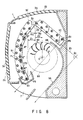
- FIG. 3 shows an indoor unit comprising a heat exchanger 5A according to a second embodiment of the present invention.
- Each of heat radiating fins 12A constituting the heat exchanger 5A has a curved portion above a cut 16.
- the heat radiating fin 12A is bent at the cut 16, so as to form a front side heat exchanger 5c and a rear side heat exchanger 5d, which constitute an inverted V-shaped heat exchanger 5A.
- the heat exchanging area is increased as compared to the straight rear side heat exchanger 5b as described above.
- all the drain water generated in the rear side heat exchanger 5d drops in the rear drain pan 6b, i.e., none of the drain water drops on the cross flow fan 8.
- the heat radiating fin 12A is in the same conditions as in the above embodiment shown in FIG. 1, i.e., the front side heat exchanger 5c, which is formed in advance by a press-punching process, is curved in a U-shaped; the lower end portion Da of the front side heat exchanger 5c is located under the cross flow fan 8 in the plane S of projection; and the line I connecting the lower end portion Da of the front side heat exchanger and the lower end portion Aa of the rear side heat exchanger 5d is located outward in respect of the central axis O of the cross flow fan 8. Therefore, the same advantages as in the above embodiment can be obtained.
- FIG. 4 shows an indoor unit comprising a heat exchanger 5B according to a third embodiment of the present invention.
- each of heat radiating fins 12B constituting the heat exchanger 5B end faces forming an inverted V shape are connected to each other, i.e., a space due to the cut 16 as described with reference to FIGS. 1 and 3 is not formed.
- An upper portion Az is first connected to the heat radiating fin 12B via a connect portion A0, left between two cuts formed at an acute angle on both edge portions, as indicated by a two-dot-and-dash line shown in FIG. 4.
- the heat exchanger is in the same conditions as in the above embodiments, except that the front side heat exchanger 5e, which is formed in advance by a press-punching process, is curved in a U-shaped. Therefore, the same advantages as in the above embodiments can be obtained.
- FIGS. 5, 6A and 6B show a fourth embodiment of the present invention.
- FIG. 5 shows an indoor unit comprising a heat exchanger 5C according to the fourth embodiment.
- the structure of the indoor unit is basically the same as that of the above embodiment, except for the heat exchanger 5C (described below), although there is a slight structural difference therebetween. That is, the indoor unit comprises an unit body 1, an air filter 4, a front drain pan 6a, a rear drain pan 6b, an air outlet port 7, a cross flow fan 8, i.e., an air blowing fan of an indoor air blowing device, a fan casing 9, a heat insulating material 10 and a hole 11.
- the air inlet port is constituted by a front inlet port 2a and a rear inlet port 2b, in which grills 3a and 3b are fitted, respectively.
- Each of heat radiating fins 12C constituting the heat exchanger 5C has a cut 20 on an air introducing side of its upper portion A.
- the heat radiating fin 12C is bent at the cut 20, thereby forming an inverted V-shaped heat exchanger 5C consisting of a front side heat exchanger 5g and a rear side heat exchanger 5h.
- a number of notch portions 21 are formed below the cut 20 at predetermined intervals therebetween in its longitudinal direction, from one side edge to the other.
- the heat radiating fin 12 is bent at the notch portions 21, thereby forming a front side heat exchanger 5g which is bent in a number of stages and substantially U-shaped.
- FIG. 6A shows a heat radiating fin 12C, which has not yet been bent.
- the heat radiating fin 12C is very narrow and long.
- the heat radiating fin 12C has a number of attachment holes 22 through which heat exchanging pipes are inserted.
- the attachment holes 22 are arranged in two columns in a staggered fashion.
- Raised slits 23 are formed in the heat radiating fin 12C, as will be described later.
- a zigzag cut 20 extends from the left side edge of the fin to a portion immediately before the right side edge thereof in FIG. 6A, i.e., from the air inlet side of the fin to a position in close proximity to the air outlet side thereof.
- the notch portions 21 are formed at predetermined intervals below the cut 20 over a lower portion C. They extend from the right side edge of the fin to a portion immediately before the left side edge thereof in FIG. 6A, i.e., from the air outlet side of the fin to a position in close proximity to the air inlet side thereof. Upper and lower edges of each notch portion are shaped zigzag at different angles.
- FIG. 6B is an enlarged view showing the notch portion 21 and its periphery.
- the raised slits 23 are formed between the attachment holes 22 and along the upper end lower edges of the notch portion 21. Each slit is cut and raised from both surfaces of the fin and the raised portion is parallel to the fin surface.
- the shape of the raised slits 23 formed between the notch portions 21 and between the attachment holes 22 is referred to as an A pattern; the shape of the raised slits formed along the lower edges of the notch portions 21 is referred to as a B pattern; and the shape of the raised slits formed along the upper edges of the notch portions is referred to as a C pattern.
- the height of the air conditioner can be reduced.
- the distance between the front side heat exchanger 5g and the cross flow fan 8 can be uniform, thereby improving the heat exchanging efficiency.
- the relationship between the heat exchanger 5C and the cross flow fan 8 is the same as in the aforementioned embodiments, i.e., the lower end portion Da of the front side heat exchanger 5g is located under the cross flow fan 8 in the plane S of projection; and the line I connecting the lower end portion Da of the front side heat exchanger 5g and the lower end portion Aa of the rear side heat exchanger 5h is located outward in respect of the central axis O of the cross flow fan 8. Therefore, the same advantages as in the above embodiments can be obtained.
- the cut 20 formed in the upper portion of the heat radiating fin 12C is bent; however, a notch portion can be provided instead of the cut to bend the fin. Further, the notch portions 21 can be replaced by cuts to form a substantially U-shaped portion of the fin.
- FIGS. 7A, 7B and 7C It is possible to use a heat radiating fin 12D as shown in FIGS. 7A, 7B and 7C.
- the overall shape, the cut 20, the notch portions 21 and the attachment holes 22 are the same as those shown in FIGS. 6A and 6B.
- Raised slits 24 are formed in every other space between adjacent upper and lower attachment holes 22 in an upper portion A above the cut 20 and in every space between adjacent upper and lower attachment holes between the notch portions.
- Each slit is constituted by a pair of cut pieces raised from both sides of the fin 12D. The faces of the cut pieces are parallel to the fin surface.
- An inverted V-shaped portion is formed by bending the aforementioned fin 12D at the cut 20 as shown in FIG. 5.
- a substantially U-shaped portion is formed by bending the notch portions 21.
- the distance between the heat exchanging pipes on both sides of a bent portion is smaller than that between the heat exchanging pipes in an unbent portion.
- the difference in distance results in a difference in ventilation resistance with respect to air flowing through the heat exchanger. It is natural that the shorter the distance, the greater the ventilation resistance. The shorter distance portions correspond to the bent portions.
- the ventilation resistance in the bent portions is substantially the same as that in the portions in which the raised slits 24 are formed.
- the heat exchanging efficiency can be uniform.
- FIG. 8 shows an indoor unit of the air conditioning machine according to a fifth embodiment of the present invention.
- a unit body 1 has a front inlet port 2a, in which a grill 3a is fitted, and an upper inlet port 2b, in which a grill 3b is fitted.
- An air outlet port 7 is formed in a region from a front portion of the unit body 1 to the bottom thereof.
- An air filter (not shown) is formed opposing to the front and upper inlet ports 2a and 2b above the air outlet port 7.
- a heat exchanger 5E and a cross flow fan 8A are arranged inside the filter.
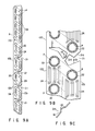
- the heat exchanger 5E is made up of heat radiating fins 12E as shown in FIGS. 9A and 9B.
- Each of the heat radiating fins 12E is very narrow and long.
- the heat radiating fins 12E are arranged in a direction perpendicular to the drawing at small intervals.
- Each fin has a plurality of attachment holes 22 arranged in two columns in a staggered fashion in the drawing.
- the heat exchanging pipes P are inserted through the attachment holes and engaged with them.
- the heat radiating fin 12E is formed in advance by a press-punching process. It has a cut 20 extending horizontally in a region between one edge 12a and in a middle portion and V-shaped from the middle portion to a portion immediately before the other edge 12b.
- a plurality of notch portions 21 are formed below the cut 20 at intervals.
- Each of the notch portions 21 is defined by an upper edge 21 a and a lower edge 21 b.
- Each of the edges has zigzag sides bent in different directions.
- the top end of the notch 21 is ranging to a portion immediately before the edge 12a.
- a bridge 21 c is formed integral with the fin 12E in a middle portion of each notch portion 21.
- the bridge 21 c is a narrow arm connecting middle portions of the upper and lower edges 21 a and 21 b and forms predetermined angles with respect to the edges 12a and 12b.
- a middle portion of the bridge 21 c is bent to project in one direction so as to form a triangular cross section, and folds 18 are formed at top and base portions of the triangle.
- raised slits 24 are formed between adjacent upper and lower attachment holes 22, except for the space between the attachment holes 22 on the upper and lower sides of the cut 20 and the space between the attachment holes 22 on the upper and lower sides of each of the notch portions 21.
- Each of the raised slits 24, extending in the longitudinal direction of the fin 12E, is formed of raised pieces cut from the fin and raised from both surfaces thereof.
- the raised slits 24 can thus be efficiently brought into contact with air to be heat-exchanged, which is flowing along the both surfaces of the fin.
- a U-shaped heat exchanging pipe P is inserted through adjacent attachment holes 22 on the right and left columns formed in the heat radiating fins 12E and engaged with them by pipe-expanding means.
- the U-shaped heat exchanging pipe P is inserted through adjacent attachment holes on the right and left columns in the region between the upper end of the heat radiating fin 12E and the cut 20, the region between the cut 20 and the uppermost notch portion 21, the region between adjacent notch portions and the region between the lower most notch portion and the lower end of the heat radiating fin 12E.
- the U-shaped heat exchanging pipe is never laid over the cut 20 or the notch portion 21.
- the heat radiating fin 12E is bent inward at the cut and the notch portions by applying force in a direction from the edge 12a toward the other edge 12b of the heat radiating fin 12E.
- the heat radiating fin 12E is bent backward at the cut 20 at an acute angle, thereby forming an inverted V-shaped heat exchanger 5E having a front side heat exchanger 5i and a rear side heat exchanger 5j.
- the front side heat exchanger is bent at the aforementioned notch portions 21, so that the upper and lower edges 21 a and 21 b of each notch portion 21 are brought into contact with each other.
- the heat exchanging sections above and below each notch portion 21 are bent inward.
- the bridges 21 formed in the notch portions 21 are folded along the folds 18 so as to project in one direction, thereby maintaining the rigidity around the notch portions 21.
- U bends 17 are provided on the left column and U bends 18 are provided on the right column in FIG. 10.
- the adjacent U bends 17 and 18 are parallel to each other.
- the left side U bends 17 are located on the air introducing side and the right side U bends 18 are located on the air discharging side of the front side heat exchanger 5i.
- the left side U bends 17 for connecting adjacent upper and lower openings of the heat exchanging pipes P are regular type U bends, which have conventionally been used, since the distance between the openings remains unchanged before and after the process of bending the heat exchanger.
- the right side U bends 18 (hatched in FIGS. 10A and 10B) for connecting adjacent upper and lower openings of the heat exchanging pipes P are formed in accordance with the distance between the openings of the heat exchanging pipes in the state where the cut portions 21 have been bent, and connect the openings.
- Each of the U bends 18 is laid across the bent notch portion 21. If the bend angle 0 is determined, the distance between the openings of the heat exchanging pipes P on both sides of the notch portion 21 can also be determined. In other words, the U bends 18 on the right column are formed in accordance with the bend angle 0 and connected with the heat exchanging pipes P.
- the U bend 19, provided on the right column, is also formed in accordance with the bend angle 0 and connected with the heat exchanging pipes P.
- the U bends 17 in the rear side heat exchanger 5j are conventional regular type U bends, since the distance between the openings of the heat exchanging pipes P remains unchanged, due to its structure, before and after the process of bending the heat exchanger.
- the overall heat exchanger 5E is inverted V-shaped.
- the front side heat exchanger 5i is bent in stages at the same angle of 0, with the edge 12b being directed inward, to form a curve.
- the rear side heat exchanger 5j is straight and rectangular.
- the ratio of the area of the front side heat exchanger 5i to that of the rear side heat exchanger 5j should be at least 2:1. It is preferable that the area of the front side heat exchanger 5i is twice or greater than that of the rear side heat exchanger 5j.
- An angle 8a formed between the right edge of the uppermost portion of the front side heat exchanger 5i and a vertical line to passing through a connect portion 25 between the front and rear side heat exchangers 5i and 5j is more acute than an angle l a formed between the left edge of the rear side heat exchanger 5j and the vertical line to.
- the uppermost portion of the front side heat exchanger 5i is inclined steep and the rear side heat exchanger 5j is inclined gently.
- the lower end of the front side heat exchanger 5i is located 1 1 forward in respect of the connect portion 25.
- End plates (not shown) is attached to both ends of the heat exchanger 5E.
- the heat exchanger 5E is arranged in a predetermined portion of the unit body 1 by means of the end plates.
- a front drain pan 6a is formed under the lower end of the front side heat exchanger 5i and a rear drain pan 6b is formed under the lower end of the rear side heat exchanger 5j.
- the drain pans 6a and 6b communicate with each other through a passage (not shown), so that drainage collected in the rear drain pan 6b flows to the front drain pan 6b through the passage.
- a cross flow fan 8A i.e., an air blowing fan of an indoor air blowing device, is arranged at the rear of the heat exchanger 5i.
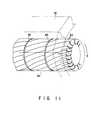
- the cross flow fan 8A has a number of blades 80 arranged in a circumferential direction and its cross section is circular.
- the blades 80 are provided between partitioning plates 8b arranged at intervals in the axial direction of the cross flow fan 8A.
- the cross flow fan is a skew type fan in which the blades 80 are twisted so as to have an angle of sweepforward with respect to a direction of rotation.
- the cross flow fan 8A is located at the rear of the front side heat exchanger 5i and part of the circumferential surface thereof is surrounded by the front side heat exchanger with a gap therebetween.
- the distance between the circumferential surface and the rear surface of the front side heat exchanger gradually increases and decreases. The variance in distance is much smaller than that in the conventional apparatus (e.g., the apparatus disclosed in Jpn. UM Appln. KOKAI Publication No. 4-57073).
- the connect portion 25 between the front side heat exchanger 5i and the rear side heat exchanger 5j is located 1 2 forward in respect of the central axis O of the cross flow fan 8A.
- a line l a connecting the lowermost heat exchanging pipe Pa of the front side heat exchanger 5i and the lowermost heat exchanging pipe Pb of the rear side heat exchanger 5j is located outward in respect of the central axis O of the cross flow fan 8A.
- the line l a crosses a prolongation l b b of the rear side heat exchanger 5j at right angles.
- a fan casing 9A is formed, ranging from the bottom portion of the rear drain pan 6b through the side of the cross flow fan 8A to an air outlet port 7.
- a tangent line l c in contact with a lower portion of the air outlet port 7 of the casing 9A crosses the extension line 1 b of the rear side heat exchanger 5j at right angles.
- the tangent line l c in contact with the lower portion of the air outlet port 7 of the casing 9A is parallel with the line 1 connecting the lowermost heat exchanging pipe Pa of the front side heat exchanger 5i and the lowermost heat exchanging pipe Pb of the rear side heat exchanger 5j.
- the front and rear side heat exchangers 5i and 5j in the heat exchanger 5E form an inverted V shape, the heights of the heat exchanger 5 and the unit body 1 can be reduced. This contributes to the reduction of the space required for the air conditioner.
- the heat exchanger 5i Since the front side heat exchanger 5i is bent at a plurality of portions, the heat exchanger 5i surrounds part of the circumferential surface of the cross flow fan 8A, so that the difference between the maximum and minimum distances between the heat exchanger 5i and the cross flow fan 8A can be very small.
- the front side heat exchanger 5i allows passage of a greater amount of air as compared to the rear side heat exchanger 5j. Therefore, since the pressure and amount of air to be heat-exchanged, taken in by the heat exchanger 5E as a whole, are quite constant, the sound of blowing air is reduced and the heat-exchanging efficiency is improved.
- the notch portions 21 of the front side heat exchanger 5i have the same shape and bend at the same angle 0, the ventilation resistances of the air to be heat-exchanged, passing through the bent portions, are the same, and the pressure and amount of air to be heat-exchanged are constant. Thus, the sound of blowing air is much reduced and the heat exchanging efficiency is further improved.
- the amount of air passing through the front inlet port 2a is greater than that of air passing through the upper inlet port 2b, on account of their areas and positions.
- the heat exchanging performance of the front and rear side heat exchangers 5i and 5j respectively opposing to the inlet ports 2a and 2b
- the heat exchanging performance of the front side heat exchanger 5i is greater than that of the rear side heat exchanger 5j, on account of their structure and the amount of air passed through the heat exchangers.
- the amount of drainage produced in the front side heat exchanger 5i during a cooling operation is greater than that in the rear side heat exchanger 5j.
- the drainage does not drop from a middle portion of the front side heat exchanger 5i, due to the steep angle of the front side heat exchanger 5i, it does not wet the interior of the unit body 1 or discharged into the room along with air blown by the cross flow fan.
- Drainage is also generated in the rear side heat exchanger 5j, but the amount thereof is very little, due to the amount of the air introduced thereto and the area of the heat exchanger 5j.
- the ratio of the area of the front side heat exchanger 5i to that of the rear side heat exchanger 5j is set to at least 2:1, a greater amount of drainage is generated in the front side heat exchanger 5i having the greater area. It is preferable that the area of the front side heat exchanger 5i be twice or greater than that of the rear side heat exchanger 5j, so that a more remarkable effect can be obtained.
- the ventilation resistance of air through the bent portion is set equal to that of the adjacent raised slit 24, the ventilation resistances in all the portions of the front side heat exchanger 5i can be the same. Therefore, the sound of blowing air is much reduced and the heat exchanging efficiency is further improved.
- the bend angles of the bent portions of the front side heat exchanger are the same angle of 0, all the bent portions can be formed with the same jig in a process of producing a heat exchanger. Thus, the manufacturing efficiency is improved.
- the U bends 18 connecting over the bent notch portions 21 are compatible with each other and not limited to a specific position in a designated column.
- the U bends 17 used in the other portion are also compatible with each other and not limited to a specific position in the other column.
- the U bends 17 and 18 are respectively manufactured by common parts and the manufacturing cost is not increased.
- the connecting positions of the U bends 17 to 19 are definitive: the U bends 17 are positioned in the air inlet side of the heat exchanger; the U bends 18 are positioned in the air outlet side thereof; and the U bend 19 is connected over the bent cut portion 20.
- the notch portions 21 of the heat radiating fin 12E are bent.
- the present invention is not limited to this embodiment.
- a plurality of cut portions can be bent at the same angle.
- the cut portion and the notch portions 21 can be formed from the one edge 12a toward the other edge 12b, unlike in the above embodiment.
- the bent front side heat exchanger has a greater air inlet side and a smaller air outlet side.
- a triangular space is formed.
- the same advantages as in the aforementioned embodiment can be obtained: the sound of blowing air due to air current turbulence can be reduced; the U bends can be used in common; and the manufacturing efficiency and the workability can be improved.
- the front and rear side heat exchangers 5i and 5j are bent from a single heat radiating fin 12E.
- the front and rear side heat exchangers 5i and 5j can be formed independently and arranged to form an inverted V shape.
- the front side heat exchanger 5i is bent in a number of stages to form a substantially circular arc, so that a portion opposing to the central axis O of the cross flow fan 8A most projects toward the front inlet port 2a.
- the lowermost heat exchanging pipe Pa is located forward by a distance 1, in respect of the connect portion 25.
- the line î is parallel with the tangent line t c .
- the central axis line l b crosses the tangent line 1, at right angles.
- a filter (not shown) can be easily inserted in or drawn out from the space.
- an air outlet port 7 having a greater open area can be formed, resulting in that the amount of blown air can be increased and the air blowing efficiency can be improved, since the front drain pan 6a also serves as the nose of the air outlet port 7.
- the rear side heat exchanger 5j introducing a smaller amount of air as compared to the front side heat exchanger 5i, is straight and does not have a bent portion, an efficient heat exchange can be performed without air current turbulence.
- the flow rate of air to be heat exchanged flows through the front side heat exchanger 5i varies as indicated by the dot-and-dash line on account of the structure of the heat exchangers.
- the dot-and-dash line is close to the front side heat exchanger 5i where the flow rate is low (slow) and away from the heat exchanger where the flow rate is high (fast).
- the ventilation resistance is great in the bent portions (the bent notch portions 21), the flow rate of air is low. In the other portions, since the ventilation resistance is relatively small, the flow rate of air is higher. Thus, a high flow rate portion and a low flow rate portion appear alternately, resulting in turbulence of air.
- bent portions of the front side heat exchanger 5i are formed along the axial direction of the cross flow fan 8A, the turbulence of air passing through these portions are introduced into the cross flow fan 8A in the same phase.
- the cross flow fan is of a skew type in which the blades 80 are twisted so as to have an angle of sweepforward with respect to a direction of rotation, the blades 80 are phase-shifted with respect to the turbulence of air introduced in the same phase.
- the phase shift of the blades 80 disperses the sound of blowing air due to the turbulence of blowing air to be heat-exchanged, performing a function of suppressing the sound of blowing air and achieving a silent operation.
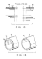
- a front side heat exchanger 5m and a rear side heat exchanger 5n as shown in FIG. 13 can be used.
- FIG. 13 shows heat radiating fins 12m constituting the front side heat exchanger 5m, a fin pitch Fpa of the fins 12m, heat radiating fins 12n constituting the rear side heat exchanger 5n and a fin pitch Fpb of the fins 12n.
- the fin pitch Fpa of the heat radiating fins 12m of the front side heat exchanger 5m is set at a narrow pitch 110 as in the above embodiment, whereas the fin pitch Fpb of the heat radiating fins 12n of the rear side heat exchanger 5n is set at a broad pitch t20.
- the fin pitch Fpb of the rear side heat exchanger 5n be an integer number of times that of the fin pitch FPa of the front side heat exchanger 5m.
- a necessary number of heat radiating fins 12E as described above are prepared and upper portions above the cut portions 20 of heat radiating fins, of the number corresponding to the ratio of the fin pitch in the rear side heat exchanger 5n to the fin pitch in the front side heat exchanger 5m, are cut off in advance.
- the cut-off portions of the fins are disposed of, and the remaining lower portions of the fins are arranged at intervals 120 corresponding to the fin pitch Fpb of the front side heat exchanger 5m.
- the heat radiating fins with the upper portions are arranged at intervals corresponding to the fin pitch Fpb of the rear side heat exchanger 5n.
- the heat radiating fins of a single type be prepared and the necessary number of fins, corresponding to the ratio of fin pitch of the rear side heat exchanger 5n to that the front side heat exchanger 5m, be additionally processed (cut). Therefore, the influence to the cost is suppressed.
- air introduced through the grill 3a fitted in the front inlet port 2a flows mainly to the front side heat exchanger 5n and air introduced through the grill 3b fitted in the upper inlet port 2b flows mainly to the rear side heat exchanger 5m.
- the fin pitch Fpa of the heat radiating fins 12m of the front side heat exchanger 5m is set at a narrow pitch î 1 as in the above embodiment, whereas the fin pitch Fpb of the heat radiating fins 12n of the rear side heat exchanger 5n is set at a broad pitch 120. Therefore, the heat exchanging efficiency of the front side heat exchanger 5n is high and that of the rear side heat exchanger 5m is low.
- the efficiency of heat transfer in the rear side heat exchanger 5m is reduced as compared to that in the front side heat exchanger 5n by increasing the fin pitch Fpb of the rear side heat exchanger 5m.
- the refrigerant evaporating temperature in a cooling operation is lowered, thereby improving the dehumidifying performance.
- the cooling performance is improved by means of the inverted V-shaped heat exchanger, while the dehumidifying performance can also improved due to the fin pitches as mentioned above.
- the refrigerant In a heating operation, the refrigerant is condensed and radiates heat of condensation. At this time also, since the fin pitch Fpb is set broad, the refrigerant condensing temperature is high.
- the fin pitch Fpb of the rear side heat exchanger 5n is set broader than that in the front side heat exchanger 5m in order to lower the efficiency of heat transfer in the rear side heat exchanger 5n.
- the following means may be employed for the same purpose.
- the heat radiating fin 12E as described above is used without being processed.
- a grooved tube so-called a ripple tube, in which minute grooves 30 are formed integral with the tube as shown in FIG. 14, is used as a heat exchanging pipe Po of a front side heat exchanger 5p.
- a heat exchanging pipe P of a rear side heat exchanger 5j is a normal pipe having no groove in an inner or outer surface.
- the efficiency of heat transfer of the front side heat exchanger 5p is increased, although that of the rear side heat exchanger 5j remains unchanged. Therefore, the dehumidifying performance of the rear side heat exchanger 5j in a cooling operation is improved, the drainage is collected without dropping, and the heat exchanging efficiency of the overall heat exchanger is also improved.
- raised slits (cut and raised slits) 24 are formed in a heat radiating fin 12E constituting a front side heat exchanger 5i.
- a heat radiating fin 12q constituting a rear side heat exchanger 5i does not have any raised slit but is flat.
Landscapes
- Engineering & Computer Science (AREA)
- Chemical & Material Sciences (AREA)
- Combustion & Propulsion (AREA)
- Mechanical Engineering (AREA)
- General Engineering & Computer Science (AREA)
- Physics & Mathematics (AREA)
- Thermal Sciences (AREA)
- Air Filters, Heat-Exchange Apparatuses, And Housings Of Air-Conditioning Units (AREA)
Abstract
Description
- The present invention relates to an air conditioning machine having indoor and outdoor units, and more particularly to an improvement of the heat exchangers provided in the indoor and outdoor units.
- An air conditioner in general comprises an indoor unit positioned in a room to be air-conditioned and an outdoor unit positioned outdoors, which are connected to each other via refrigerant tubes and electrical wires.
- Since users' demands for a decrease in the size and space required for these units has been increasing, manufacturers must increase the heat exchanging performance of an air conditioner, while satisfying the user's demand.
- For this purpose, for example, a middle portion of the heat exchanger in the vertical direction of an indoor unit is bent at an obtuse angle and protruded outward, so that the heat exchange area is maintained, while the height of the heat exchanger is reduced, thereby reducing the height of the unit body.
- The indoor unit comprises an air blowing fan for taking air in the room into the unit body, causing the air to flow through the heat exchanger, subjecting the air to heat exchange, and blowing the heat-exchanged air back into the room. A cross flow fan is selected as the air blowing fan in view of its property.
- The length of the cross flow fan in its axial direction is substantially the same as the width of the heat exchanger. The cross flow fan comprises circular end plates, partitioning plates arranged at intervals, and a number of blades arranged along the circumferential end portions of the partitioning plates. The cross section of the cross flow fan is substantially circular.
- In order to suppress the size of the unit body to as small as possible, the diameter of the cross flow fan is set to as small a size as possible, while still being capable of providing the necessary amount of air.
- In the above heat exchanger, the cross flow fan is arranged at the back of the bent portion. Depending on the position of the bent portion, at least one of the upper and lower ends of the heat exchanger is spaced apart far from the cross flow fan.
- The heat-exchanged air is not sufficiently introduced to portions apart from the heat exchanger, resulting in inconsistencies in heat exchange efficiency in different portions.
- Jpn. UM Appln. KOKAI Publication No. 4-68921 discloses a heat exchanger having an improved structure to overcome the above problem.
- As shown in FIG. 16, a heat exchanger H is divided into three parts, so that an upper portion forms an acute angle (an inverted V shape), and a front portion is bent at an obtuse angle and protruded outward. A fan F is arranged in the heat exchanger H.
- With this heat exchanger H, the height thereof can be reduced as compared with a heat exchanger in which only the middle portion is bent. In addition, since the upper and lower end portions of the heat exchanger can be positioned near the fan F, the heat exchange efficiency can be improved.
- However, in a front portion Ha of the heat exchanger H corresponding to a front inlet port a, through which the greatest amount of air is introduced, since the middle portion of the heat exchanger is bent at an obtuse angle and protruded outward as in the conventional heat exchanger described above, the distances (La to Ld) between the back surface of the front portion Ha and the circumferential surface of the fan F differ greatly from each other.
- As a result, in that portion of the heat exchanger H corresponding to a front inlet port a, through which the greatest amount of air is introduced, the air inlet pressure is liable to vary, resulting in a lack of uniformity in the amount of inlet air.
- In addition, since the fan F generates a rustling sound when blowing air, a silent operation cannot be achieved. Moreover, since the amount of inlet air is not uniform, the heat exchange efficiency improves very little. Further improvement of the heat exchanger is required.
- An object of the present invention is to provide an air conditioning machine, in which the shape and structure of heat radiating fins constituting a heat exchanger are optimized to reduce the height of the heat exchanger, thereby reducing the size of the heat exchanger and the unit body; the distance between the heat exchanger and the circumferential surface of the air blowing fan is uniform, so that the inlet air pressure and the amount of inlet air can be uniform; the air blowing sound can be reduced; and the heat exchange efficiency can be improved.
- The air conditioner of the present invention comprises:
- an air conditioning main body having an inlet port and an outlet port;
- an air blowing fan, provided in the air conditioning main body, for introducing air in a room into the air conditioning main body through the inlet port and blowing the air into the room through the outlet port, the air blowing fan having a circular cross section; and
- a heat exchanger provided in an indoor air introducing side of the air blowing fan, bent at a portion along a longitudinal direction of the heat exchanger at an acute angle, and having a front side heat exchanger located on a front side of the air conditioning machine and curved along the circular cross section of the air blowing fan and a rear side heat exchanger located on a rear side thereof.
- This invention can be more fully understood from the following detailed description when taken in conjunction with the accompanying drawings, in which:
- FIGS. 1, 2A and 2B show an indoor unit of an air conditioning machine according to a first embodiment of the present invention, in which
- FIG. 1 is a longitudinal cross-sectional view of the indoor unit;
- FIG. 2A is a longitudinal cross-sectional view of a heat exchanger of the indoor unit;
- FIG. 2B is a perspective view of part of a heat radiating fin of the indoor unit;
- FIG. 3 is a longitudinal cross-sectional view of an indoor unit according to a second embodiment of the present invention;
- FIG. 4 is a longitudinal cross-sectional view of an indoor unit according to a third embodiment of the present invention;
- FIGS. 5, 6A and 6B show a further embodiment of the present invention, in which
- FIG. 5 is a longitudinal cross-sectional view of an indoor unit;
- FIG. 6A is a front view of a heat exchanger of the indoor unit shown in FIG. 5;
- FIG. 6B is an enlarged view of part of a heat radiating fin of the indoor unit shown in FIG. 5;
- FIG. 7A is a front view of another heat radiating fin;
- FIG. 7B is an enlarged view of part of the heat radiating fin;
- FIG. 7C is a perspective view of the heat radiating fin;
- FIGS. 8 to 12 show a fifth embodiment of the present invention, in which
- FIG. 8 is a longitudinal cross-sectional view of an indoor unit;
- FIG. 9A is a front view of a fin used in a heat exchanger of the indoor unit shown in FIG. 8;
- FIG. 9B is an enlarged view of part of a heat radiating fin of the indoor unit shown in FIG. 8;
- FIG. 9C is a side view of a bridge section of the heat radiating fin;
- FIG. 10A is a cross-sectional view of the heat exchanger of the indoor unit shown in FIG. 8;
- FIG. 10B is a perspective view of part of the heat exchanger of the indoor unit shown in FIG. 8;
- FIG. 11 is a perspective view of part of a cross-flow fan of the indoor unit shown in FIG. 8;
- FIG. 12 is a diagram for explaining a function of the cross-flow fan shown in FIG. 11 with respect to a heat exchanger;
- FIG. 13 is a diagram showing pitches of heat radiating fins according to another embodiment of the present invention;
- FIG. 14 is a diagram for explaining an internal structure of a heat exchanging pipe according to another embodiment of the present invention;
- FIG. 15 is a longitudinal cross-sectional view of a heat exchanger according to another embodiment of the present invention; and
- FIG. 16 is a longitudinal cross-sectional view of a conventional indoor unit.
- A first embodiment of the present invention will be described with reference to FIGS. 1, 2A and 2B.
- An indoor unit of an air conditioning machine is constructed as shown in FIG. 1.
- An
air inlet port 2 opens in a front portion of aunit body 1 and part of an upper portion thereof and agrill 3 is fitted in theair inlet port 2. - An
air filter 4 and a heat exchanger 5 (described below) are provided, opposing to theair inlet port 2. - A front drain pan 6a is formed below a front lower portion of the
heat exchanger 5 and arear drain pan 6b is formed at the rear of theheat exchanger 5. The drain pans 6a and 6b communicate with each other through a passage (not shown). The outer bottom surface of the front drain pan 6a also serves as the nose of anair outlet port 7, which opens on a lower front portion of theunit body 1. - A
cross flow fan 8, i.e., an air blowing fan of an indoor air blowing device, is arranged at the rear of theheat exchanger 5. Afan casing 9 is formed, ranging from an upper end portion of theheat exchanger 5 through the side of thecross flow fan 8 to theair outlet port 7. - A space between the
fan casing 9 and the inner wall of theunit body 1 is filled with aheat insulating material 10. Ahole 11, through which an auxiliary pipe, a drain hose and lead lines are to be inserted, is formed in part of theheat insulating material 10. - The
heat exchanger 5 will now be described in detail. - As shown in FIG. 2A, the
heat exchanger 5 comprisesheat radiating fins 12 and heat exchanging pipes P which are inserted through theheat radiating fins 12 and engaged with them. - The
heat radiating fins 12 are arranged in a direction perpendicular to the drawing at small intervals therebetween. The heat exchanging pipes P are inserted through attachment holes 13 formed in theheat radiating fins 12 and engaged with them by pipe-expanding means. - Each of the heat exchanging pipes P is bent like a U-shape. One end of the pipe, projecting through the heat radiating fin, is bent like a U-shape, and the other end projecting through the heat radiating fin is opened.
- The opened ends of two adjacent heat exchanging pipes P are connected with a U bend (not shown). In this manner, all the heat exchanging pipes P of the
heat exchanger 5 are connected one another, thereby forming one flow passage. - The
heat radiating fin 12 is formed in advance by a press-punching process, and has a straight upper end portion inclined at an angle in FIG. 1 and a U-shaped curved portion extending under the upper end portion. - Side edges 12a and 12b of the
heat radiating fin 12 are straight and parallel with each other in a region between an upper portion A and a central portion B. However, in a region between the central portion B and a lower portion C, a curvature R1 of one side edge 12a is different from a curvature R2 of theother side edge 12b. - Thus, that region between the central portion B and the lower portion C is curved and substantially U-shaped.
- A
cut 16, extending from one side edge 12a to the proximity of theother side edge 12b, is formed in a predetermined portion of the upper portion A. - When the
heat exchanger 5 is to be assembled, a portion above thecut 16 is rotated clockwise, i.e., from the position indicated by the two-dot-and-dash line shown in FIG. 2A to the position indicated by the solid line. Thus, part of theheat exchanger 5 is bent backward at an acute angle, i.e., in an inverted V-shape. - Since the bent portion A, located above the
cut 16, is positioned in the rear side of theunit body 1, it is referred to as a rearside heat exchanger 5b. The portion under thecut 16, located in the front side of theunit body 1, is referred to as a front side heat exchanger 5a. - Most part of the front side heat exchanger 5a is curved in a U-shape, while the upper portion thereof is straight.
- A number of raised
slits 15 are formed in theheat radiating fin 12. As shown in FIG. 2B, parallel cuts are formed in theheat radiating fin 12 and portions between two adjacent cuts are raised so as to project forward and backward. - The raised slits 15 are set perpendicular to the flow of the heat-exchanged air, as indicated by the two-dot-and-dash line in FIG. 2B.
- The
heat exchanger 5 thus constructed is arranged at a predetermined position of theunit body 1, as shown in FIG. 1. The lower end of the front side heat exchanger 5a is positioned on the front drain pan 6a and the lower end of the rearside heat exchanger 5b is positioned on therear drain pan 6b. - The aforementioned inverted V-shaped portion formed by the upper portions of the front and rear
side heat exchangers 5a and 5b is located above a central axis O of thecross flow fan 8, so that these heat exchangers lie over thecross flow fan 8. - Further, since the
cross flow fan 8 is located at the rear of the substantially U-shaped front side heat exchanger 5a, the front side heat exchanger 5a surrounds part of the circumferential surface of thecross flow fan 8. - The distance between the circumferential surface of the
cross flow fan 8 and therear side edge 12b of the front side heat exchanger 5a gradually increases and decreases. The variance in distance is much smaller than that in the conventional apparatus (e.g., the apparatus disclosed in Jpn. UM Appln. KOKAI Publication No. 4-68921 shown in FIG. 16). - A lower end portion Da of the front side heat exchanger 5a, bending along the
cross flow fan 8, is located under thecross flow fan 8 in a plane S of projection indicated by a two-dot-and-dash line shown in FIG. 1. - Further, as shown in FIG. 1, a line I connecting the lower end portion Da of the front side heat exchanger 5a and a lower end portion Aa of the rear
side heat exchanger 5b is located outward in respect of the central axis O of thecross flow fan 8. In other words, theoverall heat exchanger 5 has a shape which sufficiently bends around the circumferential surface of thecross flow fan 8. - The indoor unit thus constructed performs, for example, a heating operation.
- In a heating operation, a compressor of an outdoor unit (not shown) is driven to perform a refrigerating cycle operation. In the indoor unit, the
cross flow fan 8 is driven. A refrigerant at a high temperature and a high pressure, discharged from the compressor, is introduced to theheat exchanger 5 serving as a condenser. - Air to be heat-exchanged, i.e., air in the room to be air-conditioned, is introduced through the
inlet port 2 and supplied to theheat exchanger 5 through theair filter 4. - The air is caused to flow from side edges 12a of the
heat radiating fin 12 through the gap between theheat radiating fins 12, brought into contact with theheat radiating fins 12 and the heat exchanging pipe P, and then, discharged through theother side edges 12b. - The refrigerant introduced to the
heat exchanger 5 radiates heat of condensation, while passing through the heat exchanging pipes P. The heat of condensation is transferred to theheat radiating fins 12. - The air to be heat-exchanged, flowing through the
heat radiating fins 12, performs a heat exchanging operation, in which the air to be heat-exchanged absorbs the heat, and the heated air is discharged from theheat exchanger 5 and blown out to the room through thecross flow fan 8. The room is thus heated. - Since the front and rear
side heat exchangers 5a and 5b in theheat exchanger 5 form an inverted V shape, the heights of theheat exchanger 5 and theunit body 1 can be reduced. This contributes to the reduction of the space required for the air conditioner. - In addition, since the front side heat exchanger 5a is substantially U-shaped so as to surround part of the circumferential surface of the
cross flow 8, the distance between the heat exchanger 5a and the circumferential surface of thecross flow fan 8 varies very little. - Hence, the pressure and amount of inlet air to be heat-exchanged are constant, thereby reducing the sound of blowing air and improving the heat-exchanging efficiency.
- Furthermore, the lower end portion Da of the front side heat exchanger 5a is located under the
cross flow fan 8 in the plane S of projection, and the line I connecting the lower end portion Da and the lower end portion Aa of the rearside heat exchanger 5b is located outward in respect of the central axis O of thecross flow fan 8. Since theoverall heat exchanger 5 thus sufficiently bends around the circumferential surface of thecross flow fan 8, the distance between theheat exchanger 5 and the circumferential surface of thecross flow fan 8 varies very little. Accordingly, non-uniformity in heat exchanging efficiency of theheat exchanger 5 is prevented. - Since each of the
heat radiating fins 12 is formed in advance by a press-punching process, the front side heat exchanger 5a, which is particularly complex, can be easily obtained without an additional artificial process, such as cutting or notching. Moreover, since cut and notch scraps resulting from the artificial process are not produced, the process of manufacturing theheat exchanger 5 of this embodiment is economically advantageous. FIG. 3 shows an indoor unit comprising aheat exchanger 5A according to a second embodiment of the present invention. - In this case, since the structure of the indoor unit is completely the same as that of the first embodiment, except for a
heat exchanger 5A (described below), the same elements as in the first embodiment are identified with the same reference numerals and descriptions thereof are omitted. - Each of
heat radiating fins 12A constituting theheat exchanger 5A has a curved portion above acut 16. Theheat radiating fin 12A is bent at thecut 16, so as to form a front side heat exchanger 5c and a rearside heat exchanger 5d, which constitute an inverted V-shapedheat exchanger 5A. - Since the rear
side heat exchanger 5d is curved, the heat exchanging area is increased as compared to the straight rearside heat exchanger 5b as described above. In addition, all the drain water generated in the rearside heat exchanger 5d drops in therear drain pan 6b, i.e., none of the drain water drops on thecross flow fan 8. - The
heat radiating fin 12A is in the same conditions as in the above embodiment shown in FIG. 1, i.e., the front side heat exchanger 5c, which is formed in advance by a press-punching process, is curved in a U-shaped; the lower end portion Da of the front side heat exchanger 5c is located under thecross flow fan 8 in the plane S of projection; and the line I connecting the lower end portion Da of the front side heat exchanger and the lower end portion Aa of the rearside heat exchanger 5d is located outward in respect of the central axis O of thecross flow fan 8. Therefore, the same advantages as in the above embodiment can be obtained. - FIG. 4 shows an indoor unit comprising a heat exchanger 5B according to a third embodiment of the present invention.
- In this case, since the structure of the indoor unit is completely the same as that of the above embodiments, except for the heat exchanger 5B (described below), the same elements as in the above embodiments are identified with the same reference numerals and descriptions thereof are omitted.
- In each of heat radiating fins 12B constituting the heat exchanger 5B, end faces forming an inverted V shape are connected to each other, i.e., a space due to the
cut 16 as described with reference to FIGS. 1 and 3 is not formed. - An upper portion Az is first connected to the heat radiating fin 12B via a connect portion A0, left between two cuts formed at an acute angle on both edge portions, as indicated by a two-dot-and-dash line shown in FIG. 4.
- In this state, when the upper portion Az is bent so that end faces are brought into contact with each other, an inverted V-shaped heat exchanger 5B, consisting of a front
side heat exchanger 5e and a rearside heat exchanger 5f with no space interposed therebetween, is obtained. - Since the heat exchanging area of the heat exchanger 5B is increased, air introduced to this heat exchanger is subjected to sufficient heat exchange, thus improving the heat exchanging efficiency.
- The heat exchanger is in the same conditions as in the above embodiments, except that the front
side heat exchanger 5e, which is formed in advance by a press-punching process, is curved in a U-shaped. Therefore, the same advantages as in the above embodiments can be obtained. - FIGS. 5, 6A and 6B show a fourth embodiment of the present invention.
- FIG. 5 shows an indoor unit comprising a
heat exchanger 5C according to the fourth embodiment. - The structure of the indoor unit is basically the same as that of the above embodiment, except for the
heat exchanger 5C (described below), although there is a slight structural difference therebetween. That is, the indoor unit comprises anunit body 1, anair filter 4, a front drain pan 6a, arear drain pan 6b, anair outlet port 7, across flow fan 8, i.e., an air blowing fan of an indoor air blowing device, afan casing 9, aheat insulating material 10 and ahole 11. The air inlet port is constituted by a front inlet port 2a and arear inlet port 2b, in which grills 3a and 3b are fitted, respectively. - Each of
heat radiating fins 12C constituting theheat exchanger 5C has acut 20 on an air introducing side of its upper portion A. - The
heat radiating fin 12C is bent at thecut 20, thereby forming an inverted V-shapedheat exchanger 5C consisting of a front side heat exchanger 5g and a rearside heat exchanger 5h. - A number of
notch portions 21 are formed below thecut 20 at predetermined intervals therebetween in its longitudinal direction, from one side edge to the other. - The
heat radiating fin 12 is bent at thenotch portions 21, thereby forming a front side heat exchanger 5g which is bent in a number of stages and substantially U-shaped. - FIG. 6A shows a
heat radiating fin 12C, which has not yet been bent. - The
heat radiating fin 12C is very narrow and long. - The
heat radiating fin 12C has a number of attachment holes 22 through which heat exchanging pipes are inserted. The attachment holes 22 are arranged in two columns in a staggered fashion. Raised slits 23 are formed in theheat radiating fin 12C, as will be described later. - In an upper portion A of the
heat radiating fin 12C, a zigzag cut 20 extends from the left side edge of the fin to a portion immediately before the right side edge thereof in FIG. 6A, i.e., from the air inlet side of the fin to a position in close proximity to the air outlet side thereof. - The
notch portions 21 are formed at predetermined intervals below thecut 20 over a lower portion C. They extend from the right side edge of the fin to a portion immediately before the left side edge thereof in FIG. 6A, i.e., from the air outlet side of the fin to a position in close proximity to the air inlet side thereof. Upper and lower edges of each notch portion are shaped zigzag at different angles. - FIG. 6B is an enlarged view showing the
notch portion 21 and its periphery. - The raised slits 23 are formed between the attachment holes 22 and along the upper end lower edges of the
notch portion 21. Each slit is cut and raised from both surfaces of the fin and the raised portion is parallel to the fin surface. - The shape of the raised slits 23 formed between the
notch portions 21 and between the attachment holes 22 is referred to as an A pattern; the shape of the raised slits formed along the lower edges of thenotch portions 21 is referred to as a B pattern; and the shape of the raised slits formed along the upper edges of the notch portions is referred to as a C pattern. - The raised slits 23 of the above three patterns, formed in the
heat radiating fin 12C, perform an efficient heat exchange with respect to air flowing through the slits. - Referring to FIG. 5 again, with the
heat exchanger 5C having theheat radiating fin 12C as described above, the height of the air conditioner can be reduced. In addition, the distance between the front side heat exchanger 5g and thecross flow fan 8 can be uniform, thereby improving the heat exchanging efficiency. - The relationship between the
heat exchanger 5C and thecross flow fan 8 is the same as in the aforementioned embodiments, i.e., the lower end portion Da of the front side heat exchanger 5g is located under thecross flow fan 8 in the plane S of projection; and the line I connecting the lower end portion Da of the front side heat exchanger 5g and the lower end portion Aa of the rearside heat exchanger 5h is located outward in respect of the central axis O of thecross flow fan 8. Therefore, the same advantages as in the above embodiments can be obtained. - In the above embodiment, the
cut 20 formed in the upper portion of theheat radiating fin 12C is bent; however, a notch portion can be provided instead of the cut to bend the fin. Further, thenotch portions 21 can be replaced by cuts to form a substantially U-shaped portion of the fin. - It is possible to use a heat radiating fin 12D as shown in FIGS. 7A, 7B and 7C. The overall shape, the
cut 20, thenotch portions 21 and the attachment holes 22 are the same as those shown in FIGS. 6A and 6B. - Raised slits 24 are formed in every other space between adjacent upper and lower attachment holes 22 in an upper portion A above the
cut 20 and in every space between adjacent upper and lower attachment holes between the notch portions. - Three
slits 24, arranged side by side in the width direction of the fin 12D, constitute a set. Each slit is constituted by a pair of cut pieces raised from both sides of the fin 12D. The faces of the cut pieces are parallel to the fin surface. - An inverted V-shaped portion is formed by bending the aforementioned fin 12D at the
cut 20 as shown in FIG. 5. A substantially U-shaped portion is formed by bending thenotch portions 21. - Further, in this heat radiating fin 12D, since raised slits are not formed on both the upper and lower sides of the
cut 20 and both the upper and lower sides of eachnotch portion 21, the rigidity of thefin 12 near the cut and notch portions can be maintained. - Since the fin 12D is bent at the
cut 20 and thenotch portions 21, the distance between the heat exchanging pipes on both sides of a bent portion is smaller than that between the heat exchanging pipes in an unbent portion. - The difference in distance results in a difference in ventilation resistance with respect to air flowing through the heat exchanger. It is natural that the shorter the distance, the greater the ventilation resistance. The shorter distance portions correspond to the bent portions.
- However, since raised slits are not formed in the bent portions, the ventilation resistance in the bent portions is substantially the same as that in the portions in which the raised slits 24 are formed. Thus, the heat exchanging efficiency can be uniform.
- FIG. 8 shows an indoor unit of the air conditioning machine according to a fifth embodiment of the present invention.
- A
unit body 1 has a front inlet port 2a, in which a grill 3a is fitted, and anupper inlet port 2b, in which agrill 3b is fitted. - An
air outlet port 7 is formed in a region from a front portion of theunit body 1 to the bottom thereof. An air filter (not shown) is formed opposing to the front andupper inlet ports 2a and 2b above theair outlet port 7. Aheat exchanger 5E and across flow fan 8A are arranged inside the filter. - The
heat exchanger 5E is made up ofheat radiating fins 12E as shown in FIGS. 9A and 9B. - Each of the
heat radiating fins 12E is very narrow and long. Theheat radiating fins 12E are arranged in a direction perpendicular to the drawing at small intervals. Each fin has a plurality of attachment holes 22 arranged in two columns in a staggered fashion in the drawing. The heat exchanging pipes P are inserted through the attachment holes and engaged with them. - The
heat radiating fin 12E is formed in advance by a press-punching process. It has acut 20 extending horizontally in a region between one edge 12a and in a middle portion and V-shaped from the middle portion to a portion immediately before theother edge 12b. - A plurality of
notch portions 21 are formed below thecut 20 at intervals. - Each of the
notch portions 21 is defined by an upper edge 21 a and a lower edge 21 b. Each of the edges has zigzag sides bent in different directions. The top end of thenotch 21 is ranging to a portion immediately before the edge 12a. - A bridge 21 c is formed integral with the
fin 12E in a middle portion of eachnotch portion 21. The bridge 21 c is a narrow arm connecting middle portions of the upper and lower edges 21 a and 21 b and forms predetermined angles with respect to theedges 12a and 12b. - As shown in FIG. 9C, a middle portion of the bridge 21 c is bent to project in one direction so as to form a triangular cross section, and folds 18 are formed at top and base portions of the triangle.
- Referring to FIGS. 9A and 9B again, raised
slits 24 are formed between adjacent upper and lower attachment holes 22, except for the space between the attachment holes 22 on the upper and lower sides of thecut 20 and the space between the attachment holes 22 on the upper and lower sides of each of thenotch portions 21. - Each of the raised slits 24, extending in the longitudinal direction of the
fin 12E, is formed of raised pieces cut from the fin and raised from both surfaces thereof. The raised slits 24 can thus be efficiently brought into contact with air to be heat-exchanged, which is flowing along the both surfaces of the fin. - A U-shaped heat exchanging pipe P is inserted through adjacent attachment holes 22 on the right and left columns formed in the
heat radiating fins 12E and engaged with them by pipe-expanding means. - More specifically, as indicated by a two-dot-and-dash line in FIG. 9A, the U-shaped heat exchanging pipe P is inserted through adjacent attachment holes on the right and left columns in the region between the upper end of the
heat radiating fin 12E and thecut 20, the region between thecut 20 and theuppermost notch portion 21, the region between adjacent notch portions and the region between the lower most notch portion and the lower end of theheat radiating fin 12E. In other words, the U-shaped heat exchanging pipe is never laid over thecut 20 or thenotch portion 21. - In this state, a straight plate-like heat exchanger is formed, and thereafter it is bent at the
cut 20 and thenotch portions 21. - The
heat radiating fin 12E is bent inward at the cut and the notch portions by applying force in a direction from the edge 12a toward theother edge 12b of theheat radiating fin 12E. - As shown in FIGS. 10A and 10B, the
heat radiating fin 12E is bent backward at thecut 20 at an acute angle, thereby forming an inverted V-shapedheat exchanger 5E having a frontside heat exchanger 5i and a rearside heat exchanger 5j. - Further, the front side heat exchanger is bent at the
aforementioned notch portions 21, so that the upper and lower edges 21 a and 21 b of eachnotch portion 21 are brought into contact with each other. The heat exchanging sections above and below eachnotch portion 21 are bent inward. - In this state, the
bridges 21 formed in thenotch portions 21 are folded along thefolds 18 so as to project in one direction, thereby maintaining the rigidity around thenotch portions 21. - With the above structure, all the
notch portions 21 of the frontside heat exchanger 5i are bent at the same angle of 0. - Finally, the openings of adjacent heat exchanging pipes P are connected by U bends 17 to 19 (to be described below).
- In the front
side heat exchanger 5i, U bends 17 are provided on the left column and U bends 18 are provided on the right column in FIG. 10. The adjacent U bends 17 and 18 are parallel to each other. - The left side U bends 17 are located on the air introducing side and the right side U bends 18 are located on the air discharging side of the front
side heat exchanger 5i. - The left side U bends 17 for connecting adjacent upper and lower openings of the heat exchanging pipes P are regular type U bends, which have conventionally been used, since the distance between the openings remains unchanged before and after the process of bending the heat exchanger.
- The right side U bends 18 (hatched in FIGS. 10A and 10B) for connecting adjacent upper and lower openings of the heat exchanging pipes P are formed in accordance with the distance between the openings of the heat exchanging pipes in the state where the
cut portions 21 have been bent, and connect the openings. - Each of the U bends 18 is laid across the
bent notch portion 21. If thebend angle 0 is determined, the distance between the openings of the heat exchanging pipes P on both sides of thenotch portion 21 can also be determined. In other words, the U bends 18 on the right column are formed in accordance with thebend angle 0 and connected with the heat exchanging pipes P. - The
U bend 19, provided on the right column, is also formed in accordance with thebend angle 0 and connected with the heat exchanging pipes P. - The U bends 17 in the rear
side heat exchanger 5j are conventional regular type U bends, since the distance between the openings of the heat exchanging pipes P remains unchanged, due to its structure, before and after the process of bending the heat exchanger. - In this manner, a single passage is constituted by the heat exchanging pipes P the U bends 17 to 19 through the inverted V-shaped
heat exchanger 5E. - Referring to FIG. 8 again, the
overall heat exchanger 5E is inverted V-shaped. The frontside heat exchanger 5i is bent in stages at the same angle of 0, with theedge 12b being directed inward, to form a curve. In contrast, the rearside heat exchanger 5j is straight and rectangular. - The ratio of the area of the front
side heat exchanger 5i to that of the rearside heat exchanger 5j should be at least 2:1. It is preferable that the area of the frontside heat exchanger 5i is twice or greater than that of the rearside heat exchanger 5j. - An angle 8a formed between the right edge of the uppermost portion of the front
side heat exchanger 5i and a vertical line to passing through aconnect portion 25 between the front and rearside heat exchangers side heat exchanger 5j and the vertical line to. - In other words, the uppermost portion of the front
side heat exchanger 5i is inclined steep and the rearside heat exchanger 5j is inclined gently. - The lower end of the front
side heat exchanger 5i is located 11 forward in respect of theconnect portion 25. - End plates (not shown) is attached to both ends of the
heat exchanger 5E. Theheat exchanger 5E is arranged in a predetermined portion of theunit body 1 by means of the end plates. A front drain pan 6a is formed under the lower end of the frontside heat exchanger 5i and arear drain pan 6b is formed under the lower end of the rearside heat exchanger 5j. - The drain pans 6a and 6b communicate with each other through a passage (not shown), so that drainage collected in the
rear drain pan 6b flows to thefront drain pan 6b through the passage. - A
cross flow fan 8A, i.e., an air blowing fan of an indoor air blowing device, is arranged at the rear of theheat exchanger 5i. Thecross flow fan 8A has a number ofblades 80 arranged in a circumferential direction and its cross section is circular. - As shown in FIG. 11, the
blades 80 are provided betweenpartitioning plates 8b arranged at intervals in the axial direction of thecross flow fan 8A. - The cross flow fan is a skew type fan in which the
blades 80 are twisted so as to have an angle of sweepforward with respect to a direction of rotation. - Referring to FIG. 8 again, the
cross flow fan 8A is located at the rear of the frontside heat exchanger 5i and part of the circumferential surface thereof is surrounded by the front side heat exchanger with a gap therebetween. The distance between the circumferential surface and the rear surface of the front side heat exchanger gradually increases and decreases. The variance in distance is much smaller than that in the conventional apparatus (e.g., the apparatus disclosed in Jpn. UM Appln. KOKAI Publication No. 4-57073). - The
connect portion 25 between the frontside heat exchanger 5i and the rearside heat exchanger 5j is located 12 forward in respect of the central axis O of thecross flow fan 8A. - A line ℓa connecting the lowermost heat exchanging pipe Pa of the front
side heat exchanger 5i and the lowermost heat exchanging pipe Pb of the rearside heat exchanger 5j is located outward in respect of the central axis O of thecross flow fan 8A. The line ℓa crosses a prolongation ℓb b of the rearside heat exchanger 5j at right angles. - A
fan casing 9A is formed, ranging from the bottom portion of therear drain pan 6b through the side of thecross flow fan 8A to anair outlet port 7. A tangent line ℓc in contact with a lower portion of theair outlet port 7 of thecasing 9A crosses the extension line 1 b of the rearside heat exchanger 5j at right angles. The tangent line ℓc in contact with the lower portion of theair outlet port 7 of thecasing 9A is parallel with theline 1 connecting the lowermost heat exchanging pipe Pa of the frontside heat exchanger 5i and the lowermost heat exchanging pipe Pb of the rearside heat exchanger 5j. - With the above indoor unit, since the front and rear
side heat exchangers heat exchanger 5E form an inverted V shape, the heights of theheat exchanger 5 and theunit body 1 can be reduced. This contributes to the reduction of the space required for the air conditioner. - Since the front
side heat exchanger 5i is bent at a plurality of portions, theheat exchanger 5i surrounds part of the circumferential surface of thecross flow fan 8A, so that the difference between the maximum and minimum distances between theheat exchanger 5i and thecross flow fan 8A can be very small. - The front
side heat exchanger 5i allows passage of a greater amount of air as compared to the rearside heat exchanger 5j. Therefore, since the pressure and amount of air to be heat-exchanged, taken in by theheat exchanger 5E as a whole, are quite constant, the sound of blowing air is reduced and the heat-exchanging efficiency is improved. - Further, since the
notch portions 21 of the frontside heat exchanger 5i have the same shape and bend at thesame angle 0, the ventilation resistances of the air to be heat-exchanged, passing through the bent portions, are the same, and the pressure and amount of air to be heat-exchanged are constant. Thus, the sound of blowing air is much reduced and the heat exchanging efficiency is further improved. - The amount of air passing through the front inlet port 2a is greater than that of air passing through the
upper inlet port 2b, on account of their areas and positions. - As regards the heat exchanging performances of the front and rear
side heat exchangers inlet ports 2a and 2b, the heat exchanging performance of the frontside heat exchanger 5i is greater than that of the rearside heat exchanger 5j, on account of their structure and the amount of air passed through the heat exchangers. - Therefore, the amount of drainage produced in the front
side heat exchanger 5i during a cooling operation is greater than that in the rearside heat exchanger 5j. - Since the inclination angle 8a of the front side heat exchanger is steep, the produced drainage immediately flows down along the steeply inclined plane and collects in the front drain pan 6a.
- In other words, the drainage does not drop from a middle portion of the front
side heat exchanger 5i, due to the steep angle of the frontside heat exchanger 5i, it does not wet the interior of theunit body 1 or discharged into the room along with air blown by the cross flow fan. - Drainage is also generated in the rear
side heat exchanger 5j, but the amount thereof is very little, due to the amount of the air introduced thereto and the area of theheat exchanger 5j. - Therefore, although the inclination angle 6b is relatively gentle, all the drainage is collected in the
rear drain pan 6b without a drop from the middle portion thereof. - Thus, a sufficient space for the
cross flow fan 8A is maintained between the frontside heat exchanger 5i and the rearside heat exchanger 5j, the inclination angles of which are set to ensure that the drainage is collected without dropping. This contributes to reduce the height of theunit body 1. - Further, since the ratio of the area of the front
side heat exchanger 5i to that of the rearside heat exchanger 5j is set to at least 2:1, a greater amount of drainage is generated in the frontside heat exchanger 5i having the greater area. It is preferable that the area of the frontside heat exchanger 5i be twice or greater than that of the rearside heat exchanger 5j, so that a more remarkable effect can be obtained. - Furthermore, if the ventilation resistance of air through the bent portion is set equal to that of the adjacent raised slit 24, the ventilation resistances in all the portions of the front
side heat exchanger 5i can be the same. Therefore, the sound of blowing air is much reduced and the heat exchanging efficiency is further improved. - Since the bend angles of the bent portions of the front side heat exchanger are the same angle of 0, all the bent portions can be formed with the same jig in a process of producing a heat exchanger. Thus, the manufacturing efficiency is improved.
- Since the
bend angle 0 is the same in all the bent portions, the U bends 18 connecting over thebent notch portions 21 are compatible with each other and not limited to a specific position in a designated column. - The U bends 17 used in the other portion are also compatible with each other and not limited to a specific position in the other column.
- Thus, the U bends 17 and 18 are respectively manufactured by common parts and the manufacturing cost is not increased.
- In the front
side heat exchanger 5i, the connecting positions of the U bends 17 to 19 are definitive: the U bends 17 are positioned in the air inlet side of the heat exchanger; the U bends 18 are positioned in the air outlet side thereof; and theU bend 19 is connected over thebent cut portion 20. - Therefore, it is easy to confirm the positions where the U bends 17 to 19 are to be connected, without an error, so that the workability is improved.
- In the above embodiment, the
notch portions 21 of theheat radiating fin 12E are bent. However, the present invention is not limited to this embodiment. A plurality of cut portions can be bent at the same angle. - The cut portion and the
notch portions 21 can be formed from the one edge 12a toward theother edge 12b, unlike in the above embodiment. In this case, the bent front side heat exchanger has a greater air inlet side and a smaller air outlet side. - In a side view, a triangular space is formed. However, the same advantages as in the aforementioned embodiment can be obtained: the sound of blowing air due to air current turbulence can be reduced; the U bends can be used in common; and the manufacturing efficiency and the workability can be improved.
- In the above embodiments, the front and rear
side heat exchangers heat radiating fin 12E. However, the front and rearside heat exchangers - The front
side heat exchanger 5i is bent in a number of stages to form a substantially circular arc, so that a portion opposing to the central axis O of thecross flow fan 8A most projects toward the front inlet port 2a. - Further, the lowermost heat exchanging pipe Pa is located forward by a
distance 1, in respect of theconnect portion 25. The line î is parallel with the tangent line tc. The central axis line lb crosses thetangent line 1, at right angles. - Therefore, a sufficient space is formed between the front
side heat exchanger 5i and the front surface of theunit body 1 in a lowermost portion of the frontside heat exchanger 5i. A filter (not shown) can be easily inserted in or drawn out from the space. - At the same time, an
air outlet port 7 having a greater open area can be formed, resulting in that the amount of blown air can be increased and the air blowing efficiency can be improved, since the front drain pan 6a also serves as the nose of theair outlet port 7. - Since a side portion of the
rear drain pan 6b forms a back nose, air passing through this portion flows smoothly without turbulence. Therefore, the sound of blowing air can be reduced. - The rear
side heat exchanger 5j, introducing a smaller amount of air as compared to the frontside heat exchanger 5i, is straight and does not have a bent portion, an efficient heat exchange can be performed without air current turbulence. - As shown in FIG. 12, the flow rate of air to be heat exchanged flows through the front
side heat exchanger 5i varies as indicated by the dot-and-dash line on account of the structure of the heat exchangers. The dot-and-dash line is close to the frontside heat exchanger 5i where the flow rate is low (slow) and away from the heat exchanger where the flow rate is high (fast). - More specifically, since the ventilation resistance is great in the bent portions (the bent notch portions 21), the flow rate of air is low. In the other portions, since the ventilation resistance is relatively small, the flow rate of air is higher. Thus, a high flow rate portion and a low flow rate portion appear alternately, resulting in turbulence of air.
- Since the bent portions of the front
side heat exchanger 5i are formed along the axial direction of thecross flow fan 8A, the turbulence of air passing through these portions are introduced into thecross flow fan 8A in the same phase. - However, since the cross flow fan is of a skew type in which the
blades 80 are twisted so as to have an angle of sweepforward with respect to a direction of rotation, theblades 80 are phase-shifted with respect to the turbulence of air introduced in the same phase. - Therefore, even if the turbulence of air to be heat-exchanged is introduced along the axial direction with respect to the
cross flow fan 8A, the phase shift of theblades 80 disperses the sound of blowing air due to the turbulence of blowing air to be heat-exchanged, performing a function of suppressing the sound of blowing air and achieving a silent operation. - Further, a front
side heat exchanger 5m and a rearside heat exchanger 5n as shown in FIG. 13 can be used. - FIG. 13 shows heat radiating
fins 12m constituting the frontside heat exchanger 5m, a fin pitch Fpa of thefins 12m,heat radiating fins 12n constituting the rearside heat exchanger 5n and a fin pitch Fpb of thefins 12n. - In this embodiment, the fin pitch Fpa of the
heat radiating fins 12m of the frontside heat exchanger 5m is set at a narrow pitch 110 as in the above embodiment, whereas the fin pitch Fpb of theheat radiating fins 12n of the rearside heat exchanger 5n is set at a broad pitch t20. - It is preferable that the fin pitch Fpb of the rear
side heat exchanger 5n be an integer number of times that of the fin pitch FPa of the frontside heat exchanger 5m. - More specifically, a necessary number of
heat radiating fins 12E as described above are prepared and upper portions above thecut portions 20 of heat radiating fins, of the number corresponding to the ratio of the fin pitch in the rearside heat exchanger 5n to the fin pitch in the frontside heat exchanger 5m, are cut off in advance. - The cut-off portions of the fins are disposed of, and the remaining lower portions of the fins are arranged at
intervals 120 corresponding to the fin pitch Fpb of the frontside heat exchanger 5m. - The heat radiating fins with the upper portions are arranged at intervals corresponding to the fin pitch Fpb of the rear
side heat exchanger 5n. - As described above, it is only necessary that the heat radiating fins of a single type be prepared and the necessary number of fins, corresponding to the ratio of fin pitch of the rear
side heat exchanger 5n to that the frontside heat exchanger 5m, be additionally processed (cut). Therefore, the influence to the cost is suppressed. - In an actual operation, air introduced through the grill 3a fitted in the front inlet port 2a flows mainly to the front
side heat exchanger 5n and air introduced through thegrill 3b fitted in theupper inlet port 2b flows mainly to the rearside heat exchanger 5m. - The fin pitch Fpa of the
heat radiating fins 12m of the frontside heat exchanger 5m is set at a narrow pitch î 1 as in the above embodiment, whereas the fin pitch Fpb of theheat radiating fins 12n of the rearside heat exchanger 5n is set at abroad pitch 120. Therefore, the heat exchanging efficiency of the frontside heat exchanger 5n is high and that of the rearside heat exchanger 5m is low. - In other words, the efficiency of heat transfer in the rear
side heat exchanger 5m is reduced as compared to that in the frontside heat exchanger 5n by increasing the fin pitch Fpb of the rearside heat exchanger 5m. As a result, the refrigerant evaporating temperature in a cooling operation is lowered, thereby improving the dehumidifying performance. - Thus, the cooling performance is improved by means of the inverted V-shaped heat exchanger, while the dehumidifying performance can also improved due to the fin pitches as mentioned above.
- Thus, a great amount of drainage is generated and adhered to the rear
side heat exchanger 5n having the improved dehumidifying performance. However, since the fin pitch Fpb is set broad, the drainage easily flows down and does not remain in thefin 12n. Hence, a satisfactory heat exchanging operation is maintained without disturbing a flow of air to be heat-exchanged. - In a heating operation, the refrigerant is condensed and radiates heat of condensation. At this time also, since the fin pitch Fpb is set broad, the refrigerant condensing temperature is high.
- Since the difference in temperature between the rear
side heat exchanger 5n and the air flowing there-through can be sufficiently great, hot air of a much higher temperature can be blown out of the heat exchanger. The heating efficiency is thus improved. - In the above embodiment, the fin pitch Fpb of the rear
side heat exchanger 5n is set broader than that in the frontside heat exchanger 5m in order to lower the efficiency of heat transfer in the rearside heat exchanger 5n. However, the following means may be employed for the same purpose. - In this case, the
heat radiating fin 12E as described above is used without being processed. - In addition, a grooved tube, so-called a ripple tube, in which
minute grooves 30 are formed integral with the tube as shown in FIG. 14, is used as a heat exchanging pipe Po of a frontside heat exchanger 5p. - A heat exchanging pipe P of a rear
side heat exchanger 5j is a normal pipe having no groove in an inner or outer surface. - With this structure, the heat exchanging efficiency of the heat exchanging pipe Po in the front
side heat exchanger 5p is increased, while that of the heat exchanging pipe P in the rearside heat exchanger 5j remains unchanged. - As a result, as in the embodiment as described above, the efficiency of heat transfer of the front
side heat exchanger 5p is increased, although that of the rearside heat exchanger 5j remains unchanged. Therefore, the dehumidifying performance of the rearside heat exchanger 5j in a cooling operation is improved, the drainage is collected without dropping, and the heat exchanging efficiency of the overall heat exchanger is also improved. - In a heating operation, since the condensation temperature of the rear
side heat exchanger 5j is kept high and the difference in temperature between the rear side heat exchanger and the air flowing therethrough can be sufficiently great, hot air of a much higher temperature can be blown out of the heat exchanger. The heating efficiency is thus improved. - Further, as shown in FIG. 15, raised slits (cut and raised slits) 24 are formed in a
heat radiating fin 12E constituting a frontside heat exchanger 5i. - A heat radiating fin 12q constituting a rear
side heat exchanger 5i does not have any raised slit but is flat. - With this structure, the heat exchanging efficiency of the
heat radiating fin 12E in the frontside heat exchanger 5i is increased, while that of the heat radiating fin 12q in the rear side heat exchanger 5q remains unchanged. - As a result, as in the embodiment described above, the efficiency of heat transfer of the rear side heat exchanger 5q is lower than that of the front
side heat exchanger 5i. Therefore, the same effects as in the above embodiment are obtained. In any of the above embodiments, a comfortably- conditioned air is always obtained with a low running cost.
Claims (30)
Applications Claiming Priority (15)
| Application Number | Priority Date | Filing Date | Title |
|---|---|---|---|
| JP02274294A JP3308375B2 (en) | 1994-02-21 | 1994-02-21 | Air conditioner |
| JP22742/94 | 1994-02-21 | ||
| JP2274294 | 1994-02-21 | ||
| JP48048/94 | 1994-03-18 | ||
| JP48047/94 | 1994-03-18 | ||
| JP4804794 | 1994-03-18 | ||
| JP48049/94 | 1994-03-18 | ||
| JP4804894 | 1994-03-18 | ||
| JP4804994 | 1994-03-18 | ||
| JP04804794A JP3170546B2 (en) | 1994-03-18 | 1994-03-18 | Air conditioner |
| JP04804894A JP3170547B2 (en) | 1994-03-18 | 1994-03-18 | Air conditioner |
| JP48046/94 | 1994-03-18 | ||
| JP4804694 | 1994-03-18 | ||
| JP04804994A JP3170548B2 (en) | 1994-03-18 | 1994-03-18 | Air conditioner |
| JP04804694A JP3170545B2 (en) | 1994-03-18 | 1994-03-18 | Air conditioner |
Publications (3)
| Publication Number | Publication Date |
|---|---|
| EP0668473A2 true EP0668473A2 (en) | 1995-08-23 |
| EP0668473A3 EP0668473A3 (en) | 1997-03-12 |
| EP0668473B1 EP0668473B1 (en) | 2001-04-04 |
Family
ID=27520480
Family Applications (1)
| Application Number | Title | Priority Date | Filing Date |
|---|---|---|---|
| EP94114449A Expired - Lifetime EP0668473B1 (en) | 1994-02-21 | 1994-09-14 | Air conditioning machine |
Country Status (4)
| Country | Link |
|---|---|
| US (1) | US5573059A (en) |
| EP (1) | EP0668473B1 (en) |
| KR (1) | KR0144439B1 (en) |
| CN (1) | CN1064123C (en) |
Cited By (7)
| Publication number | Priority date | Publication date | Assignee | Title |
|---|---|---|---|---|
| EP0911587A1 (en) * | 1997-10-28 | 1999-04-28 | Tze-Li Chen | Air conditioner |
| EP0789197A3 (en) * | 1996-02-09 | 2000-11-08 | SANYO ELECTRIC Co., Ltd. | Heat exchange unit for an air conditioning system |
| EP2048465A4 (en) * | 2006-07-18 | 2013-11-20 | Daikin Ind Ltd | THERMAL EXCHANGER AND MANUFACTURING METHOD THEREOF, AIR CONDITIONER |
| CN107192116A (en) * | 2017-07-04 | 2017-09-22 | 珠海格力电器股份有限公司 | Heat exchanger unit's casing, heat exchanger unit and air conditioner |
| WO2017203230A1 (en) * | 2016-05-25 | 2017-11-30 | Power Fin Technologies Limited | Heat exchanger unit, heat exchanger assembly and method of assembling a heat exchanger |
| CN108361812A (en) * | 2017-01-25 | 2018-08-03 | 珠海格力电器股份有限公司 | Indoor unit of air conditioner |
| CN109539459A (en) * | 2018-11-01 | 2019-03-29 | 海信(山东)空调有限公司 | A kind of air supply method and air-conditioning of air-conditioning |
Families Citing this family (29)
| Publication number | Priority date | Publication date | Assignee | Title |
|---|---|---|---|---|
| AU719205B2 (en) * | 1996-08-23 | 2000-05-04 | Mitsubishi Denki Kabushiki Kaisha | Air conditioner indoor unit |
| KR100214639B1 (en) * | 1996-12-21 | 1999-08-02 | 구자홍 | Top suction cross flow type indoor unit of air conditioner |
| US5896921A (en) * | 1997-05-27 | 1999-04-27 | Daewoo Electronics Co., Ltd. | Indoor unit of an air conditioner |
| KR100315518B1 (en) | 1999-09-10 | 2001-11-30 | 윤종용 | Crossflow fan for an air conditioner |
| US6360817B1 (en) * | 1999-12-22 | 2002-03-26 | Visteon Global Technologies, Inc. | Single heat exchanger |
| KR100463521B1 (en) * | 2002-04-16 | 2004-12-29 | 엘지전자 주식회사 | uneven pitch crossflow fan |
| KR100459179B1 (en) * | 2002-04-16 | 2004-12-03 | 엘지전자 주식회사 | cross-flow fan |
| JP2004163016A (en) * | 2002-11-14 | 2004-06-10 | Daikin Ind Ltd | Indoor units for heat exchangers and air conditioners |
| JP4196346B2 (en) * | 2004-03-25 | 2008-12-17 | 三菱電機株式会社 | Air conditioner |
| US7685833B2 (en) * | 2004-06-15 | 2010-03-30 | Lg Electronics Inc. | Air conditioner |
| WO2006001563A2 (en) * | 2004-06-29 | 2006-01-05 | Lg Electronics Inc. | Indoor device of separable air conditioner |
| CN100526762C (en) * | 2006-03-28 | 2009-08-12 | 海尔集团公司 | Continuous arc evaporator of wall hung air conditioner indoor unit |
| CN201628426U (en) * | 2010-04-20 | 2010-11-10 | 珠海格力电器股份有限公司 | Three-folding evaporator and wall-mounted air conditioner with same |
| JP5409544B2 (en) * | 2010-08-04 | 2014-02-05 | 三菱電機株式会社 | Air conditioner indoor unit and air conditioner |
| CN102478299A (en) * | 2010-11-30 | 2012-05-30 | 乐金电子(天津)电器有限公司 | Motor fan assembly of indoor unit of split wall-mounted air conditioner |
| US20130248144A1 (en) * | 2012-03-26 | 2013-09-26 | Bor-Haw Chang | Fan module |
| CN104838210B (en) * | 2012-12-12 | 2017-07-18 | 三菱电机株式会社 | Outdoor unit of air conditioner |
| JP5997115B2 (en) * | 2013-09-02 | 2016-09-28 | ジョンソンコントロールズ ヒタチ エア コンディショニング テクノロジー(ホンコン)リミテッド | Air conditioner |
| WO2015040746A1 (en) * | 2013-09-20 | 2015-03-26 | 三菱電機株式会社 | Heat exchanger, air conditioner device using said heat exchanger, and method for producing said heat exchanger |
| US20150211807A1 (en) * | 2014-01-29 | 2015-07-30 | Trane International Inc. | Heat Exchanger with Fluted Fin |
| WO2016067408A1 (en) * | 2014-10-30 | 2016-05-06 | 三菱電機株式会社 | Air conditioner |
| WO2018096666A1 (en) * | 2016-11-28 | 2018-05-31 | 三菱電機株式会社 | Heat exchanger, refrigeration cycle device, and method for manufacturing heat exchanger |
| CN107631354A (en) * | 2017-09-07 | 2018-01-26 | 青岛海尔空调器有限总公司 | Wall-mounted air conditioner indoor unit and control method thereof |
| JP6843721B2 (en) * | 2017-09-27 | 2021-03-17 | ダイキン工業株式会社 | Air conditioner |
| CA3057237C (en) * | 2019-02-03 | 2021-06-08 | Gd Midea Air-Conditioning Equipment Co., Ltd. | Window air conditioner |
| CN216620016U (en) | 2021-06-01 | 2022-05-27 | 广东美的暖通设备有限公司 | Wall Mounted Air Conditioner |
| CN115435388A (en) * | 2021-06-01 | 2022-12-06 | 广东美的暖通设备有限公司 | wall mounted air conditioner |
| CN115435387A (en) * | 2021-06-01 | 2022-12-06 | 广东美的暖通设备有限公司 | wall mounted air conditioner |
| US11953215B2 (en) * | 2022-02-03 | 2024-04-09 | Tyco Fire & Security Gmbh | Panel arrangement for HVAC system |
Family Cites Families (19)
| Publication number | Priority date | Publication date | Assignee | Title |
|---|---|---|---|---|
| US1143365A (en) * | 1907-12-16 | 1915-06-15 | American Blower Co | Centrifugal fan and pump. |
| US2980990A (en) * | 1957-01-22 | 1961-04-25 | Vernco Corp | Spiral blower wheel |
| US4313493A (en) * | 1976-12-13 | 1982-02-02 | Tokyo Gas Co. Ltd. | Forced air unit |
| JPS61128038A (en) * | 1984-11-28 | 1986-06-16 | Matsushita Electric Ind Co Ltd | Air conditioner |
| US5279360A (en) * | 1985-10-02 | 1994-01-18 | Modine Manufacturing Co. | Evaporator or evaporator/condenser |
| US4670537A (en) * | 1986-01-14 | 1987-06-02 | General Electric Company | Polyphenylene ether containing amino-alkyl substituted end groups reacted with N--H compound |
| US4906219A (en) * | 1988-08-15 | 1990-03-06 | J. I. Case Company | Cleaning system for a combine |
| JPH0730926B2 (en) * | 1988-10-14 | 1995-04-10 | 松下電器産業株式会社 | Air conditioner |
| JPH0468921A (en) * | 1990-07-09 | 1992-03-04 | Mitsubishi Electric Corp | Error correction method for drawing data |
| US5211219A (en) * | 1990-07-31 | 1993-05-18 | Daikin Industries, Ltd. | Air conditioner |
| JP2940100B2 (en) * | 1990-08-10 | 1999-08-25 | カシオ計算機株式会社 | Optical element |
| JPH04103512A (en) * | 1990-08-21 | 1992-04-06 | Kao Corp | Water-based manicure cosmetic |
| JPH04177092A (en) * | 1990-11-08 | 1992-06-24 | Toshiba Corp | Heat exchanger and manufacture thereof |
| JPH04270892A (en) * | 1991-02-04 | 1992-09-28 | Mitsubishi Electric Corp | Heat exchanger |
| JPH04288420A (en) * | 1991-03-15 | 1992-10-13 | Toshiba Corp | Heat exchanger for air conditioner |
| JPH04350426A (en) * | 1991-05-27 | 1992-12-04 | Toshiba Corp | Heat exchanger for air conditioner |
| JPH058316A (en) * | 1991-07-05 | 1993-01-19 | Mitsubishi Heavy Ind Ltd | Method for manufacturing composite structure |
| JPH05164348A (en) * | 1991-12-16 | 1993-06-29 | Hitachi Ltd | Air conditioner |
| US5341650A (en) * | 1992-03-13 | 1994-08-30 | Kabushiki Kaisha Toshiba | Air conditioning apparatus having a plurality of inlets for taking in indoor air at a plurality of portions of main body thereof |
-
1994
- 1994-09-14 EP EP94114449A patent/EP0668473B1/en not_active Expired - Lifetime
- 1994-09-15 US US08/305,942 patent/US5573059A/en not_active Expired - Lifetime
- 1994-09-16 KR KR1019940023486A patent/KR0144439B1/en not_active Expired - Fee Related
- 1994-09-24 CN CN94116493A patent/CN1064123C/en not_active Expired - Lifetime
Cited By (10)
| Publication number | Priority date | Publication date | Assignee | Title |
|---|---|---|---|---|
| EP0789197A3 (en) * | 1996-02-09 | 2000-11-08 | SANYO ELECTRIC Co., Ltd. | Heat exchange unit for an air conditioning system |
| EP0911587A1 (en) * | 1997-10-28 | 1999-04-28 | Tze-Li Chen | Air conditioner |
| EP2048465A4 (en) * | 2006-07-18 | 2013-11-20 | Daikin Ind Ltd | THERMAL EXCHANGER AND MANUFACTURING METHOD THEREOF, AIR CONDITIONER |
| WO2017203230A1 (en) * | 2016-05-25 | 2017-11-30 | Power Fin Technologies Limited | Heat exchanger unit, heat exchanger assembly and method of assembling a heat exchanger |
| CN108361812A (en) * | 2017-01-25 | 2018-08-03 | 珠海格力电器股份有限公司 | Indoor unit of air conditioner |
| US11655986B2 (en) | 2017-01-25 | 2023-05-23 | Gree Electric Appliances, Inc. Of Zhuhai | Air conditioner indoor unit |
| CN107192116A (en) * | 2017-07-04 | 2017-09-22 | 珠海格力电器股份有限公司 | Heat exchanger unit's casing, heat exchanger unit and air conditioner |
| CN107192116B (en) * | 2017-07-04 | 2023-12-08 | 珠海格力电器股份有限公司 | Shell of heat exchange unit, heat exchange unit and air conditioner |
| CN109539459A (en) * | 2018-11-01 | 2019-03-29 | 海信(山东)空调有限公司 | A kind of air supply method and air-conditioning of air-conditioning |
| CN109539459B (en) * | 2018-11-01 | 2021-04-30 | 海信(山东)空调有限公司 | Air supply method of air conditioner and air conditioner |
Also Published As
| Publication number | Publication date |
|---|---|
| US5573059A (en) | 1996-11-12 |
| KR950025361A (en) | 1995-09-15 |
| CN1064123C (en) | 2001-04-04 |
| EP0668473B1 (en) | 2001-04-04 |
| EP0668473A3 (en) | 1997-03-12 |
| CN1106123A (en) | 1995-08-02 |
| KR0144439B1 (en) | 1998-08-01 |
Similar Documents
| Publication | Publication Date | Title |
|---|---|---|
| US5573059A (en) | Air conditioning machine | |
| EP0469563B1 (en) | Air conditioner | |
| JP3043051B2 (en) | Heat exchange equipment | |
| JP5417718B2 (en) | Heat exchanger | |
| AU2011200171A1 (en) | Heat exchanger, air conditioning apparatus and method for manufacturing heat exchanger | |
| JPH0791873A (en) | Fin and tube heat exchanger | |
| JP3091830B2 (en) | Air conditioner | |
| JP2011043251A (en) | Finned heat exchanger | |
| JP3048614B2 (en) | Heat exchanger | |
| AU2020476620B2 (en) | Indoor heat exchanger and indoor unit of air-conditioning apparatus | |
| JP2001355981A (en) | Heat exchanger | |
| JP3233551B2 (en) | Air conditioner | |
| JP3170548B2 (en) | Air conditioner | |
| JP2001066083A (en) | Heat exchanger | |
| JP3170545B2 (en) | Air conditioner | |
| JP2008121950A (en) | Finned heat exchanger | |
| JPH086931B2 (en) | Air conditioner | |
| JP3304536B2 (en) | Air conditioner | |
| JP3308375B2 (en) | Air conditioner | |
| JP2002054840A (en) | Air conditioner | |
| JP3257743B2 (en) | Air conditioner | |
| JP3242784B2 (en) | Heat exchanger | |
| JP7401802B2 (en) | Heat exchanger and indoor unit | |
| JPH10132372A (en) | Air conditioner | |
| JP3170546B2 (en) | Air conditioner |
Legal Events
| Date | Code | Title | Description |
|---|---|---|---|
| PUAI | Public reference made under article 153(3) epc to a published international application that has entered the european phase |
Free format text: ORIGINAL CODE: 0009012 |
|
| 17P | Request for examination filed |
Effective date: 19941011 |
|
| AK | Designated contracting states |
Kind code of ref document: A2 Designated state(s): FR GB IT |
|
| PUAL | Search report despatched |
Free format text: ORIGINAL CODE: 0009013 |
|
| AK | Designated contracting states |
Kind code of ref document: A3 Designated state(s): FR GB IT |
|
| 17Q | First examination report despatched |
Effective date: 19981120 |
|
| GRAG | Despatch of communication of intention to grant |
Free format text: ORIGINAL CODE: EPIDOS AGRA |
|
| GRAG | Despatch of communication of intention to grant |
Free format text: ORIGINAL CODE: EPIDOS AGRA |
|
| GRAH | Despatch of communication of intention to grant a patent |
Free format text: ORIGINAL CODE: EPIDOS IGRA |
|
| GRAH | Despatch of communication of intention to grant a patent |
Free format text: ORIGINAL CODE: EPIDOS IGRA |
|
| GRAA | (expected) grant |
Free format text: ORIGINAL CODE: 0009210 |
|
| AK | Designated contracting states |
Kind code of ref document: B1 Designated state(s): FR GB IT |
|
| ITF | It: translation for a ep patent filed | ||
| ET | Fr: translation filed | ||
| REG | Reference to a national code |
Ref country code: GB Ref legal event code: IF02 |
|
| PLBE | No opposition filed within time limit |
Free format text: ORIGINAL CODE: 0009261 |
|
| STAA | Information on the status of an ep patent application or granted ep patent |
Free format text: STATUS: NO OPPOSITION FILED WITHIN TIME LIMIT |
|
| 26N | No opposition filed | ||
| PGFP | Annual fee paid to national office [announced via postgrant information from national office to epo] |
Ref country code: GB Payment date: 20120912 Year of fee payment: 19 |
|
| PGFP | Annual fee paid to national office [announced via postgrant information from national office to epo] |
Ref country code: IT Payment date: 20120915 Year of fee payment: 19 Ref country code: FR Payment date: 20120926 Year of fee payment: 19 |
|
| GBPC | Gb: european patent ceased through non-payment of renewal fee |
Effective date: 20130914 |
|
| REG | Reference to a national code |
Ref country code: FR Ref legal event code: ST Effective date: 20140530 |
|
| PG25 | Lapsed in a contracting state [announced via postgrant information from national office to epo] |
Ref country code: GB Free format text: LAPSE BECAUSE OF NON-PAYMENT OF DUE FEES Effective date: 20130914 |
|
| PG25 | Lapsed in a contracting state [announced via postgrant information from national office to epo] |
Ref country code: IT Free format text: LAPSE BECAUSE OF NON-PAYMENT OF DUE FEES Effective date: 20130914 Ref country code: FR Free format text: LAPSE BECAUSE OF NON-PAYMENT OF DUE FEES Effective date: 20130930 |