EP0668459A2 - Verbessertes Kugelgelenk einer Einwellenschaltvorrichtung - Google Patents
Verbessertes Kugelgelenk einer Einwellenschaltvorrichtung Download PDFInfo
- Publication number
- EP0668459A2 EP0668459A2 EP95300887A EP95300887A EP0668459A2 EP 0668459 A2 EP0668459 A2 EP 0668459A2 EP 95300887 A EP95300887 A EP 95300887A EP 95300887 A EP95300887 A EP 95300887A EP 0668459 A2 EP0668459 A2 EP 0668459A2
- Authority
- EP
- European Patent Office
- Prior art keywords
- single shaft
- ball
- movement
- rotation
- socket
- Prior art date
- Legal status (The legal status is an assumption and is not a legal conclusion. Google has not performed a legal analysis and makes no representation as to the accuracy of the status listed.)
- Withdrawn
Links
Images


Classifications
-
- F—MECHANICAL ENGINEERING; LIGHTING; HEATING; WEAPONS; BLASTING
- F16—ENGINEERING ELEMENTS AND UNITS; GENERAL MEASURES FOR PRODUCING AND MAINTAINING EFFECTIVE FUNCTIONING OF MACHINES OR INSTALLATIONS; THERMAL INSULATION IN GENERAL
- F16H—GEARING
- F16H59/00—Control inputs to control units of change-speed-, or reversing-gearings for conveying rotary motion
-
- F—MECHANICAL ENGINEERING; LIGHTING; HEATING; WEAPONS; BLASTING
- F16—ENGINEERING ELEMENTS AND UNITS; GENERAL MEASURES FOR PRODUCING AND MAINTAINING EFFECTIVE FUNCTIONING OF MACHINES OR INSTALLATIONS; THERMAL INSULATION IN GENERAL
- F16H—GEARING
- F16H63/00—Control outputs from the control unit to change-speed- or reversing-gearings for conveying rotary motion or to other devices than the final output mechanism
- F16H63/02—Final output mechanisms therefor; Actuating means for the final output mechanisms
- F16H63/30—Constructional features of the final output mechanisms
-
- F—MECHANICAL ENGINEERING; LIGHTING; HEATING; WEAPONS; BLASTING
- F16—ENGINEERING ELEMENTS AND UNITS; GENERAL MEASURES FOR PRODUCING AND MAINTAINING EFFECTIVE FUNCTIONING OF MACHINES OR INSTALLATIONS; THERMAL INSULATION IN GENERAL
- F16H—GEARING
- F16H61/00—Control functions within control units of change-speed- or reversing-gearings for conveying rotary motion ; Control of exclusively fluid gearing, friction gearing, gearings with endless flexible members or other particular types of gearing
- F16H61/26—Generation or transmission of movements for final actuating mechanisms
-
- F—MECHANICAL ENGINEERING; LIGHTING; HEATING; WEAPONS; BLASTING
- F16—ENGINEERING ELEMENTS AND UNITS; GENERAL MEASURES FOR PRODUCING AND MAINTAINING EFFECTIVE FUNCTIONING OF MACHINES OR INSTALLATIONS; THERMAL INSULATION IN GENERAL
- F16H—GEARING
- F16H63/00—Control outputs from the control unit to change-speed- or reversing-gearings for conveying rotary motion or to other devices than the final output mechanism
- F16H63/40—Control outputs from the control unit to change-speed- or reversing-gearings for conveying rotary motion or to other devices than the final output mechanism comprising signals other than signals for actuating the final output mechanisms
- F16H63/44—Signals to the control unit of auxiliary gearing
Definitions
- Both of the disadvantages relate to the extreme rotational positions of the single shaft, i.e., those which are at plus and minus 40° from the centered position in the subject embodiment.
- the ball and socket connection has a tendency to bind, actually making it difficult in some cases to achieve the two extreme rotational positions.
- the total amount of input shift lever movement is excessive, creating somewhat of a "space" problem in the cab.
- FIG. 7 is a somewhat schematic view, including the shift pattern, illustrating the geometry of the ball and socket connection of the present invention.
- the mechanism 41 includes a single shaft 43 mounted in the housing 17 for rotation about, and axial movement along, its axis of rotation R.
- the single shaft 43 supports the three shift forks 35, 37 and 39 each of which is provided with a through bore, through which the single shaft 43 extends.
- the shift forks 35, 37 and 39 move axially with the single shaft 43 in the manner set forth in above-incorporated U.S. Patent No. 4,920, 815.
- pivot axis a will be defined as the instantaneous axis of rotation of the ball 55 within the socket 53.
- the pivot axis a is illustrated in FIG. 3 as oriented parallel to the axis of rotation R of the single shaft 43, because the present invention is concerned primarily with rotational displacement of the single shaft 43 about its axis R.
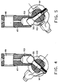
- FIGS. 4 and 5 there is illustrated a pair of rotationally displaced positions of the single shaft 43, with FIG. 4 illustrating the single shaft 43 fully rotationally displaced in the clockwise direction from the centered position of FIG. 3, and FIG. 5 representing the single shaft 43 fully rotationally displaced in the counter-clockwise direction from the centered position of FIG. 3.
- FIG. 4 illustrating the single shaft 43 fully rotationally displaced in the clockwise direction from the centered position of FIG. 3
- FIG. 5 representing the single shaft 43 fully rotationally displaced in the counter-clockwise direction from the centered position of FIG. 3.
- the actual movement of the input shift lever in the cab is opposite the movement of the "shift lever" in the single shaft shifting mechanism.
- it will be assumed hereinafter that movement within the shift pattern corresponds to movement of the block member 47.
- FIGS. 4 and 5 illustrate the extreme rotational positions of the single shaft 43, and of the ball and socket connection
- FIGS. 6 and 7 analyze the geometry of the extreme position shown in FIG. 4. It will also be understood by those skilled in the art that the analysis of FIGS. 6 and 7 applies equally to the extreme position shown in FIG. 5. As was mentioned in the BACKGROUND OF THE DISCLOSURE, it is at the extreme rotational positions of the single shaft 43 that problems have occurred with the conventional ball and socket connection between the shift lever and the single shaft.
- references hereinafter to a "ball” and “socket” clearly do not require that the ball comprise a complete, perfect sphere, or that the socket comprise a hemisphere.
- the socket of the present invention is cylindrical, as was mentioned previously, as a result of which it is possible for the ball 55 to move "vertically" relative to the socket 53, as the ball and socket pivot from the aligned, centered position of FIG. 3 toward either of the extreme positions of FIGS. 4 and 5.
- any connection or coupling which permits the movements illustrated and described herein is within the scope of the term "ball and socket”. It is essential only that the ball and socket be able to achieve the rotational motion of the single shaft 43 between the positions shown in FIGS.
- the ball and socket also facilitate the axial movement of the single shaft 43, in response to the rotation of the remote linkage member 45, and pivotal movement of the block member 47 about the axis r.
- the ball and socket should preferably permit relative pivotal movement therebetween in two planes.
- FIGS. 6 and 7 the geometry of the prior art ball and socket will be compared to the geometry of the ball and socket of the present invention.
- the shift pattern is the same for both the prior art and the invention, as far as the arrangement of the various gears, but that the pattern in FIG. 7 is more condensed or compact, for reasons which will become apparent subsequently.
- FIGS. 6 and 7 it should be noted that a comparison is being made between the centered position of the ball, and the extreme position of the ball (corresponding, for the invention, to FIG. 4).
- the comparison represents rotation of the single shaft from the centered position by an amount of rotation equal to an angle A, to the intermediate position (ninth through twelfth gears) then further rotational motion of the single shaft to the extreme position, through a further angle A.
- the angle of displacement illustrated in both FIGS. 6 and 7 is an angle 2A, while the transverse movement of the input (block member 47, shift lever, etc.) to achieve the rotational displacement through the angle 2A is represented as a linear movement of 2X.
Landscapes
- Engineering & Computer Science (AREA)
- General Engineering & Computer Science (AREA)
- Mechanical Engineering (AREA)
- Gear-Shifting Mechanisms (AREA)
- Arrangement Or Mounting Of Control Devices For Change-Speed Gearing (AREA)
- Control Of Transmission Device (AREA)
Applications Claiming Priority (2)
| Application Number | Priority Date | Filing Date | Title |
|---|---|---|---|
| US19819294A | 1994-02-17 | 1994-02-17 | |
| US198192 | 1994-02-17 |
Publications (1)
| Publication Number | Publication Date |
|---|---|
| EP0668459A2 true EP0668459A2 (de) | 1995-08-23 |
Family
ID=22732376
Family Applications (1)
| Application Number | Title | Priority Date | Filing Date |
|---|---|---|---|
| EP95300887A Withdrawn EP0668459A2 (de) | 1994-02-17 | 1995-02-13 | Verbessertes Kugelgelenk einer Einwellenschaltvorrichtung |
Country Status (6)
| Country | Link |
|---|---|
| EP (1) | EP0668459A2 (de) |
| JP (1) | JPH07310822A (de) |
| KR (1) | KR950033192A (de) |
| CN (1) | CN1117564A (de) |
| BR (1) | BR9500596A (de) |
| CA (1) | CA2142479A1 (de) |
Cited By (2)
| Publication number | Priority date | Publication date | Assignee | Title |
|---|---|---|---|---|
| WO2009153117A1 (de) * | 2008-06-19 | 2009-12-23 | Schaeffler Kg | Schaltvorrichtung |
| CN103527764A (zh) * | 2013-11-04 | 2014-01-22 | 重庆青山工业有限责任公司 | 汽车换档器定位装置 |
Families Citing this family (2)
| Publication number | Priority date | Publication date | Assignee | Title |
|---|---|---|---|---|
| DE102004006682A1 (de) * | 2004-02-11 | 2005-09-15 | Zf Friedrichshafen Ag | Einstangenschaltvorrichtung an einem Schaltgetriebe |
| DE102019214109A1 (de) * | 2019-09-17 | 2021-03-18 | Zf Friedrichshafen Ag | Bedienvorrichtung, insbesondere für eine Vorrichtung eines Kraftfahrzeugs |
-
1995
- 1995-02-13 EP EP95300887A patent/EP0668459A2/de not_active Withdrawn
- 1995-02-14 CA CA002142479A patent/CA2142479A1/en not_active Abandoned
- 1995-02-16 JP JP7051694A patent/JPH07310822A/ja active Pending
- 1995-02-17 KR KR1019950003037A patent/KR950033192A/ko not_active Application Discontinuation
- 1995-02-17 BR BR9500596A patent/BR9500596A/pt not_active Application Discontinuation
- 1995-02-17 CN CN95103225A patent/CN1117564A/zh active Pending
Cited By (3)
| Publication number | Priority date | Publication date | Assignee | Title |
|---|---|---|---|---|
| WO2009153117A1 (de) * | 2008-06-19 | 2009-12-23 | Schaeffler Kg | Schaltvorrichtung |
| CN103527764A (zh) * | 2013-11-04 | 2014-01-22 | 重庆青山工业有限责任公司 | 汽车换档器定位装置 |
| CN103527764B (zh) * | 2013-11-04 | 2016-02-03 | 重庆青山工业有限责任公司 | 汽车换档器定位装置 |
Also Published As
| Publication number | Publication date |
|---|---|
| BR9500596A (pt) | 1995-10-24 |
| JPH07310822A (ja) | 1995-11-28 |
| CA2142479A1 (en) | 1995-08-18 |
| CN1117564A (zh) | 1996-02-28 |
| KR950033192A (ko) | 1995-12-22 |
Similar Documents
| Publication | Publication Date | Title |
|---|---|---|
| EP0301724B1 (de) | Fahrzeuggetriebe | |
| DE4324333B4 (de) | Schaltungs-Steuerungssystem für ein automatisches Fahrzeuggetriebe | |
| US5357822A (en) | Transmission shifting mechanism and force attenuator therefor | |
| DE60307971T2 (de) | Schaltstellungsanzeige für ein Getriebe | |
| EP0117341A2 (de) | Getriebeschaltvorrichtung | |
| US5492209A (en) | Shift control mechanism for a multi-speed countershaft transmission | |
| US6286380B1 (en) | Automatic speed-change apparatus for a gear transmission | |
| JPH0366978A (ja) | 一軸形シフト装置 | |
| CA1146048A (en) | Transmission shift control | |
| CA1151056A (en) | Shift mechanism | |
| EP0513026B1 (de) | Getriebegangfühler | |
| CN103827554A (zh) | 用于档位段触发器的变速器超速档拨叉位置传感器 | |
| US5186070A (en) | Gear-change device for the transmission of a motor vehicle | |
| US5325739A (en) | Transmission for automotive vehicle | |
| EP0668459A2 (de) | Verbessertes Kugelgelenk einer Einwellenschaltvorrichtung | |
| US4337673A (en) | Control apparatus for a vehicle power transmission | |
| JPH0238828B2 (de) | ||
| CA1298171C (en) | Park position shift selector mechanism and method | |
| CA1092390A (en) | Double oscillating motion - single linear motion cam | |
| US5704252A (en) | Compact shift assembly with interlock | |
| GB1583901A (en) | Gearwheel changespeed gear comprising a main gearbox and a two-range auxiliary gearbox | |
| US4648283A (en) | Gear shift control mechanism | |
| US4546664A (en) | Transmission control assembly | |
| US5546825A (en) | Change gear transmission and shift rod interlock therefor | |
| US5819590A (en) | Manual transmission gear shift mechanism |
Legal Events
| Date | Code | Title | Description |
|---|---|---|---|
| PUAI | Public reference made under article 153(3) epc to a published international application that has entered the european phase |
Free format text: ORIGINAL CODE: 0009012 |
|
| STAA | Information on the status of an ep patent application or granted ep patent |
Free format text: STATUS: THE APPLICATION HAS BEEN WITHDRAWN |
|
| AK | Designated contracting states |
Kind code of ref document: A2 Designated state(s): AT DE ES FR GB IT SE |
|
| 18W | Application withdrawn |
Withdrawal date: 19950726 |