EP0667997B1 - A hierarchical synchronization method and a telecommunications system employing message-based synchronization - Google Patents
A hierarchical synchronization method and a telecommunications system employing message-based synchronization Download PDFInfo
- Publication number
- EP0667997B1 EP0667997B1 EP93924624A EP93924624A EP0667997B1 EP 0667997 B1 EP0667997 B1 EP 0667997B1 EP 93924624 A EP93924624 A EP 93924624A EP 93924624 A EP93924624 A EP 93924624A EP 0667997 B1 EP0667997 B1 EP 0667997B1
- Authority
- EP
- European Patent Office
- Prior art keywords
- synchronization
- line
- node
- message
- nodes
- Prior art date
- Legal status (The legal status is an assumption and is not a legal conclusion. Google has not performed a legal analysis and makes no representation as to the accuracy of the status listed.)
- Expired - Lifetime
Links
Images


Classifications
-
- H—ELECTRICITY
- H04—ELECTRIC COMMUNICATION TECHNIQUE
- H04J—MULTIPLEX COMMUNICATION
- H04J3/00—Time-division multiplex systems
- H04J3/02—Details
- H04J3/06—Synchronising arrangements
- H04J3/0635—Clock or time synchronisation in a network
- H04J3/0679—Clock or time synchronisation in a network by determining clock distribution path in a network
Definitions
- the invention relates to a hierarchical synchronization method for a telecommunications system employing message-based synchronization and comprising a plurality of nodes interconnected by transmission lines, wherein the nodes interchange signals containing synchronization messages with information on the priority of the respective signal in the internal synchronization hierarchy of the system.
- the invention also relates to a telecommunications system employing message-based synchronization and comprising a plurality of nodes interconnected by transmission lines and interchanging signals containing synchronization messages with information on the priority of the respective signal in the internal synchronization hierarchy of the system.
- node refers to a junction point between transmission lines in a system.
- a node may be any device or equipment capable of affecting clock synchronization, such as a branching or cross-connection means.
- Nodes in a system utilizing message-based synchronization are interconnected by transmission lines which the nodes use for data transmission. These lines also forward the clock frequency of the transmitting party to the receiving party.
- Each node selects the frequency of a signal from a neighbouring node or the frequency of its own internal clock source as the source of its own clock frequency.
- a master source In order that all nodes in the system would operate at the same clock frequency, one usually attempts to make the system to synchronize itself with a single clock source called a master source. All system nodes connected directly to the selected master source are thus synchronized with the master source while nodes connected to the nodes adjacent to the master source but not directly connected to the master source are synchronized with these adjacent nodes. Accordingly, each node at a greater distance from the master source synchronizes itself with a node one node spacing closer to the master source.
- the system nodes In order that the above-described synchronization hierarchy could be established within the system, the system nodes interchange synchronization messages. These messages contain information by means of which individual nodes are able to select a timing source. The system nodes are prioritised and the system tends to synchronize itself with the clock frequency of a node having the highest level of priority. Normally each priority level is assigned to a single system node. Synchronization messages normally contain information about the origin of the clock frequency of the node transmitting the message and the priority of the node as well as a value describing the quality of the clock signal. Accordingly, a neighbouring node clock frequency which originates from a desired node and which is of the highest quality can be selected by an individual node as the source of its own clock frequency.
- each node selects its own internal clock source as the source of its clock frequency as it has not yet processed any incoming synchronization messages. After the node has processed the first incoming synchronization messages, it selects the clock frequency of a neighbouring node having the highest level of priority as the source of its clock frequency. After all messages have been distributed over the system and the system has achieved a stable state as far as synchronization is concerned, the system has been synchronized hierarchically with the clock frequency of the master source.
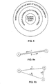
- Figure 1 shows a system utilizing message-based synchronization in a stable situation.
- Priorities assigned to the nodes are indicated by numbers within the circles representing the nodes. The smaller the number, the higher the priority of the node.
- the distribution of the clock frequency from the master clock (node 1) to the other system nodes is illustrated by solid lines. Internodal connections drawn by broken lines are not used in a normal situation for system synchronization, but they are available in change situations.
- message based synchronization is based on a simple principle that the user defined the synchronization hierarchy of the nodes by assigning each node a dedicated signature indicating the hierarchical level of the node, and the system synchronizes itself with the defined master clock independently by utilizing, if required, all existing internodal connections (cf. Figure 1). If the connection to the master clock fails, and no alternative connection exists, or if the master clock fails, the system synchronizes itself with a node of the next highest level of hierarchy.
- Figure 2 shows a situation when the master clock in the system shown in Figure 1 fails. Response to a change in synchronization takes place by message interchange between nodes.
- the synchronization hierarchy is reestablished beginning from the point of break (away from the master device of the system). This takes place e.g. in such a manner that the node that detects the break first enters into a state of internal timing for a preset time period and then forwards information about the change.
- the nest node detects the changed situation, it also enters into a state of internal timing for a preset time period and forwards information about the change, etc.
- the reestablishment of the synchronization hierarchy starts.
- the resulting hierarchy is usually similar to the original hierarchical structure where the failed connection is replaced with an operative one while the structure otherwise remains nearly unchanged.
- a network utilizing message-based synchronization is described e.g. in US Patents 2,986,723 and 4,837,850. Both patents disclose methods in which time periods depending on the size and configuration of the system are used in the case of system failures. During the time periods the nodes are forced into another state in order to prevent inappropriate synchronization in failure situations. Information about of the failure is forwarded in failure situations by using the messages of the system. After information about the changed situation has been distributed throughout the system or over a sufficiently large area, the synchronization is reestablished around the point of change or possibly also at a greater distance, if required. The time periods ensure that information about the change will be distributed over a sufficiently large area.
- the node On detecting a change/failure, the node forwards information about it and starts its own timer and proceeds in a predetermined manner (enters into a predetermined state). After the preset time has expired, the node again starts its normal procedures for obtaining timing, and the system begins to be resynchronized within portions affected by the change/failure.
- the preset time periods are dependent on the system size and configuration, they are difficult to set. In larger systems the time periods easily become too long, which impedes the maintenance of required quality in timing. When the system is expanded, the time periods have to be reset and each node has to be informed of the new time periods.
- EP-A0242117 shows a distributed timing control for a communication system having a plurality of nodes interchanging synchronization messages with information about the priority of a respective signal.
- EP-A-0435395 discloses a bidirectional synchronization method. According to the method, lines are monitored and when a link or synchronization signal on a link fails, a message indicating this is produced. If the link is used for synchronization, this node starts to search for a new reference source.
- the object of the present invention is to provide a system which avoids the time periods to be shortened without any risk of losing synchronization.
- Hierarchical synchronization method for a telecommunications system employing message-based synchronization and comprising a plurality of nodes interconnected by transmission lines (A, B), wherein the nodes interchange signals containing synchronization messages with information on the priority of the respective signal in the internal synchronization hierarchy of the system, characterized in that a transmission line between two nodes is monitored to verify its bidirectionality, and as soon as the bidirectionality of the line cannot be verified, the use of the line for synchronization is prohibited.
- a telecommunications system employing message-based synchronization and comprising a plurality of nodes interconnected by transmission lines (A, B) and interchanging signals containing synchronization messages with information on the priority of the respective signal in the internal synchronization hierarchy of the system, characterized in that the system node comprises interface-specific monitoring means for determining whether each line is uni- or bidirectional, and a synchronization decision means concealed to said monitoring means for prohibiting the use of the respective line for synchronization in response to determination that the line is uni-directional.
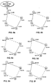
- Figure 3 illustrates a system employing self-organizing master-slave synchronization (SOMS), a prior art message-based synchronization method.
- the system comprises five nodes (or devices) which are assigned SOMS addresses according to their level of hierarchy, the addresses being indicated by the reference numerals 1...5.
- the master node of the system has the smallest SOMS address.
- the nodes interchange messages containing such SOMS addresses. In this way they are able to identify each other by means of the address numbers and establish a synchronization hierarchy so that the whole network can synchronize itself with the master node.
- a synchronization message contains three different parts: a frame structure, signature and check sum.
- the SOMS signature is the most important part of the SOMS message. It comprises three consecutive numbers D1 to D3:
- Each node compares continuously incoming SOMS signatures with each other and selects the smallest amongst them.
- the different parts D1, D2 and D3 are combined into a single number by placing them in succession (D1D2D3) (for the sake of clarity, a dash will be inserted between the different parts in the text below as follows: D1-D2-D3).
- the SOMS address (D3) of the node transmitting the SOMS message is used for the selection if the incoming signals cannot be distinguished from each other in any other way.
- the new SOMS signature can be derived from the selected smallest SOMS signature as follows: the first part (D1) is left intact; the second part (D2) is incremented by one, and the third part (D3) is replaced with the node's own SOMS address.
- Each node also has its own internal SOMS signature X-O-X, where X is the SOMS address of the node. If none of the incoming SOMS messages contains a signature smaller than the internal signature, the node uses its own internal oscillator or possibly a separate synchronization input as the source of clock frequency. Of course, the outgoing SOMS message thereby employs the internal SOMS signature.
- the nodes transmit continuously SOMS messages in all directions in order that any changed data in the SOMS signatures would be distributed as rapidly as possible and that they would know the current operating condition of neighbouring nodes.
- the SOMS signatures cannot be compared with each other until the incoming SONS messages have been accepted and the SOMS signatures have been extracted from the messages.
- the SOMS signature contained therein is accepted immediately for comparison if the message is faultless.
- the incoming transmission line has an accepted SOMS signature and faultless messages containing the same, signature are received continuously, the situation remains unchanged. If the SOMS message is found to be faulty, the current SOMS signature is retained until three successive faulty SOMS messages have been received. At this stage the old SOMS signature is no longer accepted for comparison. Waiting for three successive SOMS messages aims at eliminating temporary disturbances.
- the current SOMS signature is rejected only after a period of time corresponding to three successive SOMS messages. If the line fails totally, the SOMS signature is rejected immediately. If no appropriate SOMS signature is available for comparison due to disturbances in the incoming signal, the SOMS signature of the transmission line is rejected.
- a constant-value signature where all parts (D1, D2, D3) have their maximum value (MAX-MAX-MAX) is thereby used in the comparison as the SOMS signature of this incoming transmission line.
- each node employs its own internal synchronization source, and transmits its own internal SOMS signature X-O-X to the other nodes. This signature is also compared with incoming SOMS signatures. If none of the incoming signatures is smaller than the internal signature, the node continues to use its own internal timing.
- the SOMS network is shown in an initial state when none of the nodes (or devices) has yet processed any one of the incoming SOMS messages. In all nodes, the highest priority is assigned to the internal SOMS signature of the node as no other signatures have yet been processed.
- the SOMS signatures are indicated beside each node to which they are transmitted, and the selected signature is framed (in the initial situation shown in Figure 3 all nodes employ their internal timing source). Lines used in synchronization are drawn by a continuous line and standby lines are drawn by a broken line (in the initial situation shown in Figure 3, all lines are standby lines).
- node 1 When the nodes start to process the incoming SOMS messages, node 1 retains the use of the internal timing, nodes 2 and 4 synchronize themselves with node 1 on the basis of the signature 1-0-1, node 3 is synchronized with node 2 (2-0-2), and node 5 with node 3 (3-0-3). At the same time the nodes generate their own new SOMS signatures as described above and provide their outgoing SOMS message with the new signature.
- the network in a stable situation is shown in Figure 3. All nodes have synchronized with the master node 1 over the shortest possible path.
- Faulty synchronization signatures may remain circulating in the system portion that has no connection to the master node of the system after a change/failure, which causes e.g. unstable oscillation in synchronization.
- Figures 6a to 6f show a case in which the above-described situation occurs in a SOMS system. Nodes in the forced state of internal timing at a specific time are indicated by underlining the respective number. A line between nodes 17 and 20 is unidirectional (from node 20 to node 17, as shown by the arrow); the other lines are bidirectional. At the first stage ( Figure 6a), node 17 loses its connection to the rest of the system. On detecting that the connection has failed, node 17 is forced into the state of internal timing ( Figure 6b), and starts to transmit its internal synchronization signature 17-0-17. Due to the unidirectionality of the line, node 20, however, will not yet be informed of the failure.
- node 18 detects the change and is forced into the state of internal timing. Thereafter ( Figure 6d), node 19 is forced into the state of internal timing, and node 17 reverts to the normal state, and so it accepts the synchronization message received from node 20, being thus synchronized with node 20. It is not until after this ( Figure 6e) that the wave of forced timing reaches node 20; however, the outdated synchronization signature has already caused the loss of synchronization in the system portion shown in the figures. At the same stage node 18 has reverted to the normal state and accepted the signature from node 17. Thereafter (Figure 6f) the vicious circle continues after node 19 has reverted to the normal state, and node 17 has been forced into the state of internal timing.
- each node in its turn is forced into the state of internal state for a preset period, whereas they are otherwise synchronized with each other in accordance with their numbering.
- This vicious circle continues until the synchronization distance counter (D2) exceeds its greatest allowable value, so that the synchronization signature is found to be faulty. Before this stage, however, the synchronization has already been lost.
- the system disclosed in US Patent 4,837,850 referred to above may also result in a situation described above if the time period of the system has not been determined properly. This kind of situation may be encountered e.g. when the system is expanded, or as a result of failure when the system configuration changes. For instance, it is thereby possible that a message paging the master node has not yet been distributed over the entire system before the expiry of the time period assigned to the node that transmitted the message. In such a case, the node that transmitted the paging message may receive an outdated synchronization signature over a unidirectional line, as a result of which it will not be synchronized properly.
- the solution according to the invention enables the time periods of the system to be shortened without any risk of the loss of synchronization as a result of situations described above.
- nodes In order that the unidirectionality of an internodal line could be detected, communication is required between the nodes. In practice, such communication may vary from transmission of one bit to a handshaking procedure performed by messages.
- the prior art devices nodes
- the prior art devices have to be provided with means for determining whether the line is unidirectional or bidirectional, and means for prohibiting the use of the line for synchronization whenever the bidirectionality of the line has not been verified.
- These means are incorporated in interface-specific message processing means in the node, and depending on the implementation, possibly in the synchronization decision means of the node, which selects the synchronization signature to be applied.
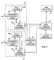
- Figure 7 shows means provided in a node for monitoring the uni/bidirectionality of a line and for selecting the timing source.
- the figure shows two lines A and B between a system node and neighbouring nodes.
- the bi- or unidirectionality of the line is determined in interface-specific transmission and reception blocks 11a and 11b.
- the transmission link of each line is connected to a signal transmission and reception means 13a and 13b, respectively, which perform the processing of the physical signal.
- the means 13a and 13b forward the synchronization message to an associated synchronization message transmission and reception means 16a and 16b, respectively.
- the synchronization message transmission and reception means e.g.
- the signal transmission and reception means 13a and 13b also monitor the quality of the received signal and store data thereon in interface-specific fault databases 24a and 24b, respectively.
- the synchronization message transmission and reception means 16a obtains the fault data from the database 24a, and the transmission and reception means 16b from the fault database 24b. Monitoring a line for a failure/change takes place in the signal transmission and reception means in a manner known per se .
- the decision means 23 compares the messages and stores them in a memory 21 e.g. in priority order so that the selected synchronization signature has always the highest status.
- the unidirectionality of the line may be attended to in two ways.
- the synchronization message transmission and reception means 16a or 16b respectively, transmits a separate message to the decision means 23 whenever it detects that the respective line is unidirectional or becomes unidirectional. So the decision means knows that this line must not be used for synchronization (and it will not store the respective signature into the memory 21).
- the synchronization message transmission and reception means 16a or 16b transmits, on being informed of the line becoming unidirectional, a synchronization signature with the worst possible value (for instance, the value MAX-MAX-MAX in the SOMS network) to the decision means 23.
- the node's own outbound synchronization signature is stored in a memory 22 which applies it to the synchronization message transmission and reception means in each interface.
- the reception end is always informed of a failure occurring in the transmission direction; in some systems, the receiving party also transmits information about the failure to the transmitting party (such as PCM lines complying with the CCITT specification G.704).
- the transmitting party such as PCM lines complying with the CCITT specification G.704.
- the line was originally bidirectional as individual transmission directions may e.g. cross between the devices. A sudden change in the switching of the lines may also cause bidirectional lines to turn into individual unidirectional lines, which cannot always be detected by means of failure identifications normally in use.
- the easiest way to prevent the use of unidirectional lines for synchronization is to include in the synchronization message to be transmitted such information that it can be determined whether a signal received from a certain direction can be used for synchronization or not. In practice, this can be accomplished by two basic alternative ways which do not require internodal communication.
- One way, which does not require any assumptions to be made, is to include in the synchronization message a synchronization path indicating all nodes through which the synchronization has passed. Each node checks whether it is already included in the synchronization path included in the message. If so, the message must not be used for synchronization as the path cannot be the shortest connection to the master node of the system. In the example of Figures 6a to 6f, for instance, node 17 would detect at the stage of Figure 6d that it is included in the synchronization path of the message from node 20, and so it would not accept the signature 1-10-20, as it normally would do. In practice, the addition of the synchronization path to the synchronization message makes the message considerably longer. It is therefore not advisable to add the path, if such information is not utilized otherwise in the synchronization.
- Unidirectional lines can be eliminated with a considerably smaller increase in the message length though it is thereby necessary to assume that an individual node is able to couple a certain incoming direction with a certain outgoing transmission direction (e.g. the device has a port having both an incoming and outgoing transmission direction). If a further assumption can be made that both transmission directions of the port are connected to the same neighbouring node, a single bit need to be added to the message to be transmitted. This bit indicates whether the port receives any identifiable messages containing a synchronization signature and whether the signal is of adequate quality. If the device obtains the above-mentioned marking bit with the incoming line of the port, it knows that the other end also obtains the message, and so the line is bidirectional and can be used for synchronization.
- each message to be transmitted has to be provided with information indicating from which node the incoming message of the port originates.
- this information is derived from the last part (D3) of the synchronization signature.
- the information possibly has to be added to the message (if it does not already exist in the message). If the incoming message of the node contains information indicating that the neighbouring node receives a message from this node at the same port from which it transmitted the message to this node, the port can be used for synchronization. This is illustrated in Figures 8a and 8b.
- the bidirectionality of the line can be detected as both nodes (1 and 2) get back their own address from the other communicating party.
- none of the nodes (4, 6 or 9) gets back its own address as none of the lines is bidirectional.
- the length of the synchronization message need not be increased needlessly when the use of unidirectional lines for synchronization is prevented by a handshaking procedure in two directions.
- a line When a line is switched on, both communicating parties shake hands to verify the bidirectionality of the line before any actual synchronization messages are transmitted.
- the handshaking is repeated after each break, and it is realized in the synchronization message.
- transmission and reception means cf. Figure 7).
- a break refers to any state in which the signal cannot be used as a source of timing. The break may thus be either a total break in communication or only a failure.
- the input signal contains an AIS (Alarm Indication Signal), the input signal has no frame alignment or CRC multiframe alignment, the error ratio in the frame alignment word of the input signal is too high, or the input signal contains a far end alarm.
- AIS Alarm Indication Signal
- Handshaking is based on the principle that one communicating party transmits its own unambiguous identity to the other party, which then has to return the received identity. When the device's own identity is returned, it has been verified that the line is bidirectional.
- Figure 9 shows a simplified example of the realization of handshaking between nodes x and y.
- Three different message types are used: message type I performs requesting, and contains the identity of the transmitting party; message type II performs both responding and requesting, and contains both identities; and message type III. performs responding, and contains the received identity.
- message type I performs requesting, and contains the identity of the transmitting party
- message type II performs both responding and requesting, and contains both identities
- message type III performs responding, and contains the received identity.
- node x detects that the line is again operative after a failure, it transmits message I, which contains a line identity (X) of the transmitting party.
- the line identity identifies the transmitting node and its port unambiguously.
- the identity consists of the node's synchronization address and the port number.
- message II contains the line identities (X and Y) of both nodes.
- node x that initiated the handshaking gets back its own identity within the message, it knows that the line is bidirectional and may return the line identity (Y) of the other communicating party by transmitting message III as an acknowledgement. Then the transmission of normal synchronization messages is started (node y transmits its own synchronization signature d1-d2-d3).
- the addresses of the parties transmitting synchronization messages may be monitored during normal synchronization communication.
- information concerning the transmitting party of the message is indicated by the last part D3 of the signature; in other methods it may be necessary to add this information to the synchronization message.
- the party transmitting the synchronization message must all the time remain the same as the transmitting party obtained as a result of the handshaking. Comparison between these addresses is performed in the synchronization message transmission and reception means ( Figure 7). If a false response or a message of the wrong type is obtained from the handshaking procedure, the received synchronization signature is rejected. In such a case the line must not be used for synchronization.
- the handshaking is restarted. If either one of the nodes suspects that there occur difficulties over the internodal line as far as bidirectionality is concerned, it may start the handshaking procedure at any time by transmitting message I.
- FIG 10 A state machine realizing the handshaking procedure described above is shown in Figure 10, in which the condition for each state transition is stated in connection with the respective transition, and a required procedure is indicated below the condition and separated from it by a dash.
- the most linear case shown in Figure 9 is indicated in Figure 10 by broken lines.
- line operative there are several alternative paths leading to the block "line operative". For instance, message II is not necessarily received after the transmission of message I (as in the linear alternative), but message I, for instance, may be received if the other end has detected that the line is again operative substantially at the same time and starts the handshaking procedure substantially simultaneously.
- the state machine shown in the figure operates on the principle that a certain message is never awaited from the other party, but the handshaking is speeded up by always taking into account the message received from the other party. For instance, if message I is received after the transmission of message I, the transmission of message II is started immediately.
Abstract
Description
Claims (9)
- Hierarchical synchronization method for a telecommunications system employing message-based synchronization and comprising a plurality of nodes interconnected by transmission lines (A, B), wherein the nodes interchange signals containing synchronization messages with information on the priority of the respective signal in the internal synchronization hierarchy of the system, characterized in that a transmission line between two nodes is monitored to verify its bidirectionality, and as soon as the bidirectionality of the line cannot be verified, the use of the line for synchronization is prohibited.
- Method according to claim 1, characterized in that the bidirectionality of the line is verified by performing a handshaking procedure in two directions between the nodes at least when the line is switched on and after a failure of the line is eliminated.
- Method according to claim 2, characterized in that an address of a party transmitting a synchronization message received at a node over a line is monitored during normal synchronization, and if the address of the transmitting party obtained as a result of the handshaking procedure is not equal to the monitored address, the use of the line for synchronization is prohibited.
- Method according to claim 3, characterized in that if the address of the transmitting party obtained as a result of the handshaking procedure is not equal to the monitored address, the handshaking procedure is restarted after a predetermined time.
- Method according to claim 1, characterized in that each synchronization message transmitted from a port in a node is provided with information indicating from which node the message entering the port originates if this information is not included in the message used in the system.
- Method according to claim 1, characterized in that the prohibition is carried out by assigning a signature corresponding to the lowest possible priority to said line.
- Telecommunications system employing message-based synchronization and comprising a plurality of nodes interconnected by transmission lines (A, B) and interchanging signals containing synchronization messages with information on the priority of the respective signal in the internal synchronization hierarchy of the system, characterized in that the system node comprises interface-specific monitoring means (11a, 11b) for determining whether each line is uni- or bidirectional, and a synchronization decision means connected to said monitoring means for prohibiting the use of the respective line for synchronization in response to determination that the line is uni-directional.
- Telecommunications system according to claim 7, characterized in that the interface-specific monitoring means (11a, 11b) comprise means (13a, 16a, 13b, 16b) for transmitting and receiving handshaking messages.
- Telecommunications system according to claim 8, characterized in that the interface-specific monitoring means further comprise means (16a; 16b) for comparing an address of the transmitting party received over the line during normal synchronization with an address of the transmitting party obtained as a result of the handshaking procedure.
Applications Claiming Priority (3)
| Application Number | Priority Date | Filing Date | Title |
|---|---|---|---|
| FI925072A FI91689C (en) | 1992-11-09 | 1992-11-09 | Hierarchical synchronization method and communication system using message-based synchronization |
| FI925072 | 1992-11-09 | ||
| PCT/FI1993/000459 WO1994011966A1 (en) | 1992-11-09 | 1993-11-08 | A hierarchical synchronization method and a telecommunications system employing message-based synchronization |
Publications (2)
| Publication Number | Publication Date |
|---|---|
| EP0667997A1 EP0667997A1 (en) | 1995-08-23 |
| EP0667997B1 true EP0667997B1 (en) | 2000-08-23 |
Family
ID=8536180
Family Applications (1)
| Application Number | Title | Priority Date | Filing Date |
|---|---|---|---|
| EP93924624A Expired - Lifetime EP0667997B1 (en) | 1992-11-09 | 1993-11-08 | A hierarchical synchronization method and a telecommunications system employing message-based synchronization |
Country Status (7)
| Country | Link |
|---|---|
| US (1) | US5734687A (en) |
| EP (1) | EP0667997B1 (en) |
| AU (1) | AU5422394A (en) |
| DE (1) | DE69329294T2 (en) |
| DK (1) | DK0667997T3 (en) |
| FI (1) | FI91689C (en) |
| WO (1) | WO1994011966A1 (en) |
Families Citing this family (23)
| Publication number | Priority date | Publication date | Assignee | Title |
|---|---|---|---|---|
| FI95978C (en) * | 1994-03-01 | 1996-04-10 | Nokia Telecommunications Oy | Hierarchical synchronization method |
| GB2301991B (en) * | 1995-06-06 | 1999-06-30 | Plessey Telecomm | SDH Network |
| FI98582C (en) * | 1995-06-28 | 1997-07-10 | Nokia Telecommunications Oy | Realization of a secure bus in a data communication network |
| FI98583C (en) * | 1995-06-28 | 1997-07-10 | Nokia Telecommunications Oy | Implementation of a certified bus in a telecommunication network |
| JP3420898B2 (en) * | 1996-10-04 | 2003-06-30 | 富士通株式会社 | Synchronization message reception processing device |
| FI103307B (en) * | 1997-02-11 | 1999-05-31 | Nokia Telecommunications Oy | Communication network synchronization |
| WO1998041041A1 (en) | 1997-03-12 | 1998-09-17 | Alcatel Network Systems, Inc. | Telecommunications network distributed restoration method and system |
| US6496476B1 (en) | 1997-03-12 | 2002-12-17 | Worldcom, Inc. | System and method for restricted reuse of intact portions of failed paths |
| US6411598B1 (en) | 1997-03-12 | 2002-06-25 | Mci Communications Corporation | Signal conversion for fault isolation |
| US6044064A (en) * | 1997-03-28 | 2000-03-28 | Mci Communications Corporation | Method and system therefor of confining path verification signals within a distributed restoration network |
| US6044084A (en) * | 1997-10-06 | 2000-03-28 | Hughes Electronics Corporation | Collision detection for packet-switched multiple-path communication system |
| US6294991B1 (en) | 1998-09-08 | 2001-09-25 | Mci Communications Corporation | Method and system therefor for ensuring a true activation of distributed restoration in a telecommunications network |
| US6418117B1 (en) | 1998-09-08 | 2002-07-09 | Mci Worldcom, Inc. | Out of band messaging in a DRA network |
| US6337846B1 (en) | 1998-09-08 | 2002-01-08 | Mci Worldcom, Inc. | Quantification of the quality of spare links in a telecommunications network |
| US6404733B1 (en) | 1998-09-08 | 2002-06-11 | Mci Worldcom, Inc. | Method of exercising a distributed restoration process in an operational telecommunications network |
| US6714563B1 (en) * | 1999-04-26 | 2004-03-30 | Cisco Technology, Inc. | Network clock synchronization scheme |
| US6813240B1 (en) | 1999-06-11 | 2004-11-02 | Mci, Inc. | Method of identifying low quality links in a telecommunications network |
| IL137086A (en) * | 2000-06-29 | 2004-06-20 | Enavis Networks Ltd | Method and system for fast synchronization of multiframe structures using periodic signatures |
| US20040003007A1 (en) * | 2002-06-28 | 2004-01-01 | Prall John M. | Windows management instrument synchronized repository provider |
| CN100369426C (en) * | 2002-11-22 | 2008-02-13 | 中兴通讯股份有限公司 | Method for judging clock source ring in sychronous digital transmission network |
| US7656804B2 (en) * | 2004-08-16 | 2010-02-02 | Motorola, Inc. | Method and apparatus for operating an AD-HOC communication system |
| US7912094B2 (en) * | 2006-12-13 | 2011-03-22 | Honeywell International Inc. | Self-checking pair-based master/follower clock synchronization |
| US8717894B2 (en) * | 2008-07-03 | 2014-05-06 | Zte Corporation | Synchronization, scheduling, network management and frequency assignment method of a layered wireless access system |
Family Cites Families (8)
| Publication number | Priority date | Publication date | Assignee | Title |
|---|---|---|---|---|
| US2986723A (en) * | 1960-02-26 | 1961-05-30 | Bell Telephone Labor Inc | Synchronization in a system of interconnected units |
| US4347490A (en) * | 1981-03-06 | 1982-08-31 | Prem Magnetics, Inc. | Low profile transformer |
| US4701756A (en) * | 1985-09-10 | 1987-10-20 | Burr William E | Fault-tolerant hierarchical network |
| US4736393A (en) * | 1986-04-16 | 1988-04-05 | American Telephone And Telegraph Co., At&T Information Systems, Inc. | Distributed timing control for a distributed digital communication system |
| DE3629931A1 (en) * | 1986-09-03 | 1988-03-10 | Philips Patentverwaltung | HIERARCHICAL SYNCHRONIZATION METHOD AND CIRCUIT ARRANGEMENT FOR SWITCHING CENTERS OF A INTERMEDIATED TELECOMMUNICATION NETWORK |
| DE3833940A1 (en) * | 1988-09-22 | 1990-04-05 | Siemens Ag | METHOD FOR RE-SYNCHRONIZING A SWITCH CENTER IN A TELECOMMUNICATION NETWORK |
| DE3943052A1 (en) * | 1989-12-28 | 1991-07-04 | Philips Patentverwaltung | HIERARCHICAL SYNCHRONIZATION METHOD FOR SWITCHING CENTERS OF A TELECOMMUNICATION NETWORK |
| JPH0575635A (en) * | 1991-09-12 | 1993-03-26 | Hitachi Ltd | Network synchronization management system and management system |
-
1992
- 1992-11-09 FI FI925072A patent/FI91689C/en not_active IP Right Cessation
-
1993
- 1993-11-08 US US08/448,355 patent/US5734687A/en not_active Expired - Lifetime
- 1993-11-08 AU AU54223/94A patent/AU5422394A/en not_active Abandoned
- 1993-11-08 WO PCT/FI1993/000459 patent/WO1994011966A1/en active IP Right Grant
- 1993-11-08 DK DK93924624T patent/DK0667997T3/en active
- 1993-11-08 EP EP93924624A patent/EP0667997B1/en not_active Expired - Lifetime
- 1993-11-08 DE DE69329294T patent/DE69329294T2/en not_active Expired - Fee Related
Also Published As
| Publication number | Publication date |
|---|---|
| WO1994011966A1 (en) | 1994-05-26 |
| FI925072A0 (en) | 1992-11-09 |
| DE69329294D1 (en) | 2000-09-28 |
| FI91689C (en) | 1994-07-25 |
| AU5422394A (en) | 1994-06-08 |
| US5734687A (en) | 1998-03-31 |
| EP0667997A1 (en) | 1995-08-23 |
| DK0667997T3 (en) | 2000-09-18 |
| FI91689B (en) | 1994-04-15 |
| DE69329294T2 (en) | 2001-02-22 |
Similar Documents
| Publication | Publication Date | Title |
|---|---|---|
| EP0667997B1 (en) | A hierarchical synchronization method and a telecommunications system employing message-based synchronization | |
| US5878095A (en) | Hierarchical synchronization method | |
| EP0748547B1 (en) | Hierarchical synchronization method | |
| US5706291A (en) | Method and apparatus for connecting two messaging systems having differing synchronizations one of which is message-based | |
| US5796793A (en) | Hierarchical synchronization method | |
| EP0667996B1 (en) | Network arrangement | |
| FI95975B (en) | Hierarchical synchronization method | |
| EP0746919A1 (en) | Network arrangement | |
| FI102442B (en) | Synchronization of a data communication network | |
| WO1994011965A1 (en) | A hierarchical synchronization method and a telecommunications system employing message-based synchronization | |
| EP0932950A1 (en) | Hierarchical synchronization system | |
| EP0872083B1 (en) | Implementing a fault-tolerant bus in a telecommunications network | |
| WO1994011964A1 (en) | Hierarchical synchronization method | |
| WO1994011963A1 (en) | A hierarchical synchronization method and a telecommunications system employing message-based synchronization |
Legal Events
| Date | Code | Title | Description |
|---|---|---|---|
| PUAI | Public reference made under article 153(3) epc to a published international application that has entered the european phase |
Free format text: ORIGINAL CODE: 0009012 |
|
| 17P | Request for examination filed |
Effective date: 19950509 |
|
| AK | Designated contracting states |
Kind code of ref document: A1 Designated state(s): DE DK FR GB IT NL SE |
|
| RAP1 | Party data changed (applicant data changed or rights of an application transferred) |
Owner name: NOKIA TELECOMMUNICATIONS OY |
|
| 17Q | First examination report despatched |
Effective date: 19980810 |
|
| GRAG | Despatch of communication of intention to grant |
Free format text: ORIGINAL CODE: EPIDOS AGRA |
|
| RAP1 | Party data changed (applicant data changed or rights of an application transferred) |
Owner name: NOKIA NETWORKS OY |
|
| GRAG | Despatch of communication of intention to grant |
Free format text: ORIGINAL CODE: EPIDOS AGRA |
|
| GRAH | Despatch of communication of intention to grant a patent |
Free format text: ORIGINAL CODE: EPIDOS IGRA |
|
| GRAH | Despatch of communication of intention to grant a patent |
Free format text: ORIGINAL CODE: EPIDOS IGRA |
|
| GRAA | (expected) grant |
Free format text: ORIGINAL CODE: 0009210 |
|
| AK | Designated contracting states |
Kind code of ref document: B1 Designated state(s): DE DK FR GB IT NL SE |
|
| REG | Reference to a national code |
Ref country code: DK Ref legal event code: T3 |
|
| REF | Corresponds to: |
Ref document number: 69329294 Country of ref document: DE Date of ref document: 20000928 |
|
| ET | Fr: translation filed | ||
| ITF | It: translation for a ep patent filed |
Owner name: BARZANO' E ZANARDO S.P.A. |
|
| PLBE | No opposition filed within time limit |
Free format text: ORIGINAL CODE: 0009261 |
|
| STAA | Information on the status of an ep patent application or granted ep patent |
Free format text: STATUS: NO OPPOSITION FILED WITHIN TIME LIMIT |
|
| 26N | No opposition filed | ||
| REG | Reference to a national code |
Ref country code: GB Ref legal event code: IF02 |
|
| PGFP | Annual fee paid to national office [announced via postgrant information from national office to epo] |
Ref country code: SE Payment date: 20031105 Year of fee payment: 11 Ref country code: NL Payment date: 20031105 Year of fee payment: 11 Ref country code: GB Payment date: 20031105 Year of fee payment: 11 |
|
| PGFP | Annual fee paid to national office [announced via postgrant information from national office to epo] |
Ref country code: FR Payment date: 20031110 Year of fee payment: 11 |
|
| PGFP | Annual fee paid to national office [announced via postgrant information from national office to epo] |
Ref country code: DK Payment date: 20031114 Year of fee payment: 11 |
|
| PGFP | Annual fee paid to national office [announced via postgrant information from national office to epo] |
Ref country code: DE Payment date: 20031120 Year of fee payment: 11 |
|
| PG25 | Lapsed in a contracting state [announced via postgrant information from national office to epo] |
Ref country code: GB Free format text: LAPSE BECAUSE OF NON-PAYMENT OF DUE FEES Effective date: 20041108 |
|
| PG25 | Lapsed in a contracting state [announced via postgrant information from national office to epo] |
Ref country code: SE Free format text: LAPSE BECAUSE OF NON-PAYMENT OF DUE FEES Effective date: 20041109 |
|
| PG25 | Lapsed in a contracting state [announced via postgrant information from national office to epo] |
Ref country code: DK Free format text: LAPSE BECAUSE OF NON-PAYMENT OF DUE FEES Effective date: 20041130 |
|
| PG25 | Lapsed in a contracting state [announced via postgrant information from national office to epo] |
Ref country code: NL Free format text: LAPSE BECAUSE OF NON-PAYMENT OF DUE FEES Effective date: 20050601 Ref country code: DE Free format text: LAPSE BECAUSE OF NON-PAYMENT OF DUE FEES Effective date: 20050601 |
|
| REG | Reference to a national code |
Ref country code: DK Ref legal event code: EBP |
|
| GBPC | Gb: european patent ceased through non-payment of renewal fee |
Effective date: 20041108 |
|
| EUG | Se: european patent has lapsed | ||
| PG25 | Lapsed in a contracting state [announced via postgrant information from national office to epo] |
Ref country code: FR Free format text: LAPSE BECAUSE OF NON-PAYMENT OF DUE FEES Effective date: 20050729 |
|
| NLV4 | Nl: lapsed or anulled due to non-payment of the annual fee |
Effective date: 20050601 |
|
| REG | Reference to a national code |
Ref country code: FR Ref legal event code: ST |
|
| PG25 | Lapsed in a contracting state [announced via postgrant information from national office to epo] |
Ref country code: IT Free format text: LAPSE BECAUSE OF NON-PAYMENT OF DUE FEES;WARNING: LAPSES OF ITALIAN PATENTS WITH EFFECTIVE DATE BEFORE 2007 MAY HAVE OCCURRED AT ANY TIME BEFORE 2007. THE CORRECT EFFECTIVE DATE MAY BE DIFFERENT FROM THE ONE RECORDED. Effective date: 20051108 |