EP0667262A1 - Two-piece clockspring with lock and wire harness assembly - Google Patents
Two-piece clockspring with lock and wire harness assembly Download PDFInfo
- Publication number
- EP0667262A1 EP0667262A1 EP95300844A EP95300844A EP0667262A1 EP 0667262 A1 EP0667262 A1 EP 0667262A1 EP 95300844 A EP95300844 A EP 95300844A EP 95300844 A EP95300844 A EP 95300844A EP 0667262 A1 EP0667262 A1 EP 0667262A1
- Authority
- EP
- European Patent Office
- Prior art keywords
- clockspring
- rotor cover
- housing
- backbone
- flat cable
- Prior art date
- Legal status (The legal status is an assumption and is not a legal conclusion. Google has not performed a legal analysis and makes no representation as to the accuracy of the status listed.)
- Granted
Links
Images


Classifications
-
- B—PERFORMING OPERATIONS; TRANSPORTING
- B60—VEHICLES IN GENERAL
- B60R—VEHICLES, VEHICLE FITTINGS, OR VEHICLE PARTS, NOT OTHERWISE PROVIDED FOR
- B60R16/00—Electric or fluid circuits specially adapted for vehicles and not otherwise provided for; Arrangement of elements of electric or fluid circuits specially adapted for vehicles and not otherwise provided for
- B60R16/02—Electric or fluid circuits specially adapted for vehicles and not otherwise provided for; Arrangement of elements of electric or fluid circuits specially adapted for vehicles and not otherwise provided for electric constitutive elements
- B60R16/023—Electric or fluid circuits specially adapted for vehicles and not otherwise provided for; Arrangement of elements of electric or fluid circuits specially adapted for vehicles and not otherwise provided for electric constitutive elements for transmission of signals between vehicle parts or subsystems
- B60R16/027—Electric or fluid circuits specially adapted for vehicles and not otherwise provided for; Arrangement of elements of electric or fluid circuits specially adapted for vehicles and not otherwise provided for electric constitutive elements for transmission of signals between vehicle parts or subsystems between relatively movable parts of the vehicle, e.g. between steering wheel and column
-
- H—ELECTRICITY
- H01—ELECTRIC ELEMENTS
- H01R—ELECTRICALLY-CONDUCTIVE CONNECTIONS; STRUCTURAL ASSOCIATIONS OF A PLURALITY OF MUTUALLY-INSULATED ELECTRICAL CONNECTING ELEMENTS; COUPLING DEVICES; CURRENT COLLECTORS
- H01R35/00—Flexible or turnable line connectors, i.e. the rotation angle being limited
- H01R35/04—Turnable line connectors with limited rotation angle with frictional contact members
-
- H—ELECTRICITY
- H01—ELECTRIC ELEMENTS
- H01R—ELECTRICALLY-CONDUCTIVE CONNECTIONS; STRUCTURAL ASSOCIATIONS OF A PLURALITY OF MUTUALLY-INSULATED ELECTRICAL CONNECTING ELEMENTS; COUPLING DEVICES; CURRENT COLLECTORS
- H01R35/00—Flexible or turnable line connectors, i.e. the rotation angle being limited
- H01R35/02—Flexible line connectors without frictional contact members
- H01R35/025—Flexible line connectors without frictional contact members having a flexible conductor wound around a rotation axis
Definitions
- the invention pertains to a clockspring interconnector for enclosing an electrical conductor cable, the clockspring interconnector electrically connecting a rotatable electric device with a stationary electric device.
- An increasing number of automobiles have air bag crash systems.
- An air bag is typically located on the steering wheel facing the driver.
- the air bag must be in continuous electrical connection with sensors in the car body.
- the sensors provide an electrical signal to the air bag crash assembly which instantly inflates the air bag in the event of a crash.
- a clockspring interconnector comprising an outer housing, a rotor member and multiple intermediate housing members for enclosing and connecting the members; the housing and rotor member rotatably associated with one another at a plurality of bearing surfaces.
- a "clockspring” is located inside the interconnector.
- the clockspring is a flat conductor cable and has two ends conductively attached to conductor wires which pass out of the interconnector to unite the air bag to the sensing device.
- the interconnector is mounted on the steering column, and the steering wheel may be rotated in either direction while a continuous, positive electrical connection is provided between air bag sensors via the clockspring interconnector.
- U.S. Patent No. 5,171,157 describes a clockspring interconnector including spring-loaded locking pegs integral to the internal hub of the rotor.
- This patent describes locking pegs which may be depressed only upon engagement from above, providing direct vertical force onto the locking pegs.
- Such a design requires that a column being inserted through the center of such a clockspring have protruding portions which will project perpendicular to the path of insertion of the column into the clockspring and provide surfaces which will engage the locking pegs in a vertical direction.
- Such a system is disadvantageous because the hub being inserted into such a clockspring must be specially designed so that the protruding portions of the hub engage the locking pegs while still allowing complete mating insertion of the column through the clockspring and with the steering assembly. Accordingly, it is desired to have a locking means which may be engaged without the need of a specially design column.
- U.S. Patent No. 5,059,134 describes a connection location where the electrical conductors of the flat ribbon cable are serially connected to a connection conductor wires via the engagement of the uninsulated end portions of conductor wires against a clamping body which is surrounded by a protective sheath injection molded about the clamping body.
- This arrangement is both difficult and costly to assemble.
- In order to position the clamping body against the conductor wires and then injection mold the protective sheath about the clamping body requires that this operation be done separately from the assembly of the flat cable within the clockspring housing. Accordingly, an improved structure is desired which allows for the simple, inexpensive and quick attachment of external conductor wires to the electrical conductors of the flat cable so that all assembly of the clockspring may occur prior to the attachment of the external cables.
- clocksprings have been known to have been assembled having at least three components.
- U.S. Patent No. 4,607,898 describes a clockspring having a first half and a second half which is a assembled by a face plate.
- the assembly of the clockspring having three or more parts is disadvantageous due to the need to manufacture and then assemble the multiple parts which is costly and time-consuming and the increased number of bearing surfaces which create noise. Accordingly, there is desired a clockspring which has only two parts and a single bearing surface and may be assembled together quickly and easily.
- Such an assembly including all of the above described advantages is possible by incorporating the structures of the present invention either in a single clockspring assembly or as individual components of separate clockspring assemblies.
- a clockspring interconnector comprising a housing defining a chamber extending therethrough and a rotor cover attached to the housing.
- a coiled flat cable carried within the chamber surrounding the rotor cover. The flat cable having a first end attached to a first connector location of the rotor cover and a second end attached to a second connector location of the housing.
- the rotor cover defines a central aperture having a top opening and a bottom opening.
- the external diameter of the aperture having integral flanges extending from the rotor cover adjacent to the bottom opening.
- the housing having a center hole having a rim at its external diameter.
- the flanges having angled surfaces to slide past the rim and a protruding surface to engage the rim of the housing and secure the rotor cover thereto.
- the first and second end of the flat cable including a backbone to receive the end of the flat cable.
- the backbone protrudes from the rotor cover at a first connection location.
- the backbone protrudes from the housing at a second connection location.
- the backbone including parallel channels for positioning the conductors of the flat cable.
- the channels of the backbone are separated by ribs and positioning ribs.
- the ribs are adjacent to the conductors of the flat ribbon cable.
- the positioning ribs receive insulated wires having uninsulated end portions. The positioning ribs engaging the wires at an insulated portion. The wires being press fit between the positioning ribs and aligned with the conductors of the flat cable.
- the positioning ribs are heat staked sufficiently to deform the positioning ribs to trap the wire within the channels.
- the uninsulated end portion of the wire is welded to the conductors of the flat cable.
- a backbone cover is attached to the backbone.
- the backbone includes a gap running transverse to the channels.
- the backbone cover includes a rib. Upon attachment of the backbone cover to the backbone having the insulated wire inserted therein, the rib engages the insulated portion of the wire, pushing the wire into the gap.
- the backbone cover is secured to the backbone by placement of a rivet through the backbone cover and the backbone.
- An automatic unlocking means is included in the rotor cover.
- the unlocking means includes a depressed or unlocked position and an undepressed or locked position.
- the locking device includes a compression spring which urges the locking assembly having a detente to engage a recess along the rim of the housing. Upon assembly of the clockspring onto a steering column, the unlocking means is depressed, disengaging the detente of the locking means from the recess of the housing allowing the rotor cover to rotate.
- a locking means having a latching body seated within a channel of the housing.
- a stop head protrudes from the latching body.
- the stop head engages a stop wing of the rotor top.
- the stop wing includes a neck portion.
- a narrow neck portion of the stop wing allows for rotation of the rotor cover in 350° and upon abutment of the stop head against the neck portion of the stop wing, the rotor cover is prohibited from making a full rotation.
- a pull tab is connected to the latching body and protrudes perpendicular to the sidewall of the housing.
- the pull tab includes an arm of sufficient length to allow for the pull tab to protrude sufficiently to be gripped subsequent to the assembly of the clockspring within a steering wheel housing and steering column housing. Pulling on the pull tab with sufficient force disengages the latching body from the channel of the housing and removes the stop head from its position, allowing the free rotation of the stop wing and rotor cover.
- a further embodiment of the present invention includes a nonreplaceable locking means preventing the rotation of the rotor cover more than 180°.
- the nonreplaceable locking means having a securement tab which remains within a slot of the clockspring after removal of the nonreplaceable locking means.
- the nonreplaceable locking means attached to the rotor cover.
- the clockspring interconnector comprising a lip protruding from the housing. A projection protruding from the housing a specified distance from the lip. A stop tab attached to the nonreplaceable locking means which will abut the lip when rotated in a first direction and the projection when rotated in a second direction.
- the clockspring interconnector includes a gripping member attached to the nonreplaceable locking means.
- the gripping member, the stop tab and the securement tab are integrally connected.
- the securement tab includes a means for separation of the securement tab from the nonreplaceable locking means.
- the means for separating the securement tab includes a bite for allowing the ripping separation of the nonreplaceable locking means from the securement tab. Removal of the nonreplaceable locking means allows the rotor cover to rotate more than 180°.
- the clockspring interconnector of this invention is better understood by references to FIGS. 1-14 which shows various aspects of a presently preferred clockspring interconnector.
- the clockspring 10 includes a housing 12 having a sidewall 14. Enclosing the top of the housing 12 is the rotor cover 16.
- the rotor cover 16 combines the separate prior art components of a rotor and a cover into a single integral component.
- the rotor cover 16 includes flanges (not shown) which allow the rotor cover 16 to snap-fit onto the housing 12.
- the main components of the clockspring 10 are only the rotor cover and the housing 12. There are no other members needed to enclose the chamber 18 of the housing 12 and no other parts needed to hold the clockspring 10 together.
- the unique design minimizes costs by having only the two parts and the two components are quickly and easily assembled, saving in labor, storage and tooling costs.
- the unique design also includes a single bearing surface at the attachment means of the flanges because the top 17 of the rotor cover 16 is separated from the housing 12 by a gap 15 and does not bear together in this area.
- the rotor cover 16 includes an aperture 20 having a top opening 21 and a bottom opening 22.
- the aperture includes an inner wall 24.
- an automatic unlocking means 30 to provide for the unlocking of the rotor cover 16 allowing it to rotate freely on the housing 12.
- the automatic unlocking means 30 includes a button 35 having a sliding surface 31 and is received in cell 32.
- the button 35 is shown in its undepressed, locked position prior to assembly of the clockspring 10 to a steering assembly. Upon assembly to a steering assembly and insertion of section of steering wheel through aperture 20 of the rotor cover 16, the steering wheel will engage sliding surface 31 and force the button 35 to move in the direction of arrow 33, transverse to the direction of insertion of the steering wheel.
- Movement of the button 35 in direction of arrow 33 causes the button 35 to recede into the cell 32 causing the front surface 34 to become flush with the inner wall 24 of aperture 20.
- the movement of the button 35 in direction of arrow 33 also causes a detente (not shown) of button 35 to disengage from a recess of the housing 12 and allow for the rotor cover 16 to rotate freely from the housing 12.
- This arrangement of the automatic unlocking means 30 allows for the shipping of the clockspring while it is in its locked position and prohibits the flat cable in the chamber 18 of the housing 12 from unwinding during shipping and causing the disalignment of the rotor cover 16 from the housing 12.
- the clockspring In the assembled state of the clockspring with a steering mechanism, it is essential that the clockspring have at least two and a half turns in each direction. Thus, it is necessary that when the clockspring is assembled to the steering mechanism that it be centered. This ensures that there be enough turns necessary for the proper functioning of the clockspring. Failure to provide the assembly of a properly centered clockspring may cause the locking of the rotor cover or rupture of the flat cable of the clockspring when turned too far in one direction.
- the unlocking means 30 slidably engages and disengages in a direction transverse to the direction of the insertion of the steering wheel assembly.
- the unlocking means 30 also allows for the removal of the clockspring from the steering assembly for repairs while prohibiting the unwinding or uncentering of the rotor cover 16 in relation to the housing 12.
- a repair worker may simply remove the clockspring 10 from the steering assembly which will cause the button 35 to disengage from cell 32 and its detente will engage the recess of the housing 12.
- This automatic unlocking means 30 ensures the rotor cover 16 is centered on the housing 12 at all times when the clockspring 10 is disassembled.
- the locking means 40 includes a latching body 41 which is seated within a channel 42 which is formed along the outer wall 14 of the housing 12. The locking means 40 is seated within the channel 42 by frictional engagement of a base portion 43 of the latching body to engage a sill 44 of the channel 42.
- a stop head 45 Integral with the latching body 41 is a stop head 45 which protrudes above the plane of the rotor cover 16.
- the stop head 45 is oriented to engage a stop wing 48 integral with the rotor cover 16.
- the stop wing 48 includes a neck portion 49.
- the rotor cover 16 may also be rotated in the clockwise direction. However, the rotor cover 16 will be prohibited from making a full rotation in that the neck portion 49 of the stop wing 48 will abut the other side of the stop head 45 and inhibit further rotation.
- the neck portion 49 is sufficiently wide so that rotation is limited to 350°.
- the enlargement of the widths of the neck portion 49 decreases the amount of rotation that is allowed by the rotor cover 16.
- the decreasing of neck portion 49 of the stop wing 48 will increase the degree of rotation that is allowed by the rotor cover 16.
- another embodiment of this invention could provide a neck portion 49 which protrudes around 180° of the rotor cover 16.
- the rotor cover would only be allowed to rotate 180° before abutting the neck portion 49 of stop wing 48.
- the clockspring 10 is assembled onto a steering assembly in which the rotor cover 16 is enclosed in a steering wheel housing and the lower portion of the housing 12 is enclosed in a steering column housing.
- This assembly may require rotation of the steering column and in turn, the steering wheel assembly.
- large degrees of rotation may be required for the easy assembly thereof.
- the clockspring 10 includes an automatic unlocking means 30, as discussed above, the assembly of the clockspring will unlock the automatic locking means and allow full rotation of the rotor cover 16 upon the housing 12. In such a case, upon conclusion of the assembly and at operation of the steering wheel, it is likely that a turn in one direction will break the flat cable, while turning in the other direction would allow rotation well beyond two and a half turns.
- the engagement of a the stop head 45 against the neck portion 49 of the stop wing 48 while prohibiting rotation of the rotor cover 16 beyond 360°, does allow for limited motion of the clockspring and steering assembly to which it is attached for the proper assembly of the steering column. Following such assembly and returning of the steering wheel to its centered position, the locking means 40 may then be removed.
- the above advantages are realized for the locking means 40 of a clockspring having both a locking means 40 and an automatic unlocking means 30 only where the steering mechanism is assembled after the clockspring is assembled to the steering column.
- Pull tab 46 is provided which protrudes perpendicular from the side wall 14 of the housing 12.
- the pull tab 46 is positioned vertically on the side wall 14 so that it protrudes from a gap which exists when a steering wheel housing is assembled above it and a steering column housing is assembled below it.
- the length of the arm 47 of the pull tab 46 is dependent upon the overhang that the steering wheel housing and the steering column housing protrude from the clockspring 10.
- the pull tab 46 includes gripping portion 78 which allows for easy pulling of the pull tab 46 and removal of the locking means 40 from the channel 42. While finger 49 maintains the latching body 41 of the locking means 40 within the channel 42, upon pulling on the pull tab 46, the base portion 43 of the latching body will ride over the finger 49 and allow removal from the channel 42.
- the stop head 45 Upon pulling of the pull tab 46, the stop head 45 will slide down the side wall 14 of the housing and follow the pull tab out and from between the gap created between the steering wheel housing and the steering column housing. Having removed the locking means 40, the clockspring 10 will be able to rotate freely. Once the locking means 40 is disengaged, it cannot be replaced within channel 42 and only provides a temporary locking feature.
- the housing 12 defines chamber 18 which houses the flat cable.
- the flat cable is wound around the inner wall 24 of the rotor cover 16.
- the flat cable has a first end and a second end.
- the first end is connected to the rotor cover 16 at a first connection location 50.
- the first connection location 50 includes a backbone 51 which is inserted through passage 58 and protrudes beyond the top surface of the rotor cover 16.
- the first connection location 50 secures the conductors of the flat cable in an accessible orientation on the backbone 51.
- external cables 60,61 may be attached quickly and easily to the backbone 51.
- the external cables 60,61 may attach to controls in the steering wheel or to a squib connector 62 which connects to an igniter which activates the air bag.
- the second end of the flat cable is terminated at a second connection location 55 having a similar construction to the first connection location and having external wires 63 attached thereto which may attach to a sensing device or power source within the engine compartment of an automobile.
- FIG. 2 a side elevation of the clockspring 10 of FIG. 1 is shown.
- the top rotor cover 16 is shown attached to the housing 12. It can be seen that there is a gap 15 which is present between the housing 12 and the rotor cover 16. Assembly of the clockspring 10 having the gap 15 allows for rotation of the rotor cover 16 on the housing 12 without having a surface for rubbing which may cause excessive noise or friction.
- the gap 15 reduces greatly the amount of bearing surfaces and provides for a much easier rotation of the clockspring 10.
- First connection location 50 is shown having backbone 51 enclosed by backbone cover 52 and having wires 53 leaving therefrom.
- a lip 54 is shown which is formed integral with the rotor cover 16 and provides for a surface for the backbone cover 52 to slide into for securement around the backbone 51.
- Locking means 40 is shown having latching body 41 and stop head 45. Second connection location 55 is shown where the second end of the flat cable is terminated. Integrally formed with the housing 12 are snap legs 11 which provide for the snap mounting of the housing to a steering column housing. Locator pegs 13 also help mount the housing 12 to a steering column housing.
- Rotor cover 16 includes aperture 20.
- the rotor cover 16 has formed thereon the first connection location 50 and the automatic unlocking means 30.
- Locking means 40 is shown attached to housing 12.
- the stop wing 48 is integrally formed with the rotor cover 16 to engage stop head 45.
- FIG. 4 a cut-away, side elevation view of FIG. 3 taken at line A-A is shown.
- rotor cover 16 is assembled directly to the housing 12.
- the housing defines a chamber 18 in which the flat cable (not shown) is housed.
- the rotor cover 16 forms an aperture 20.
- the aperture 20 includes a top opening 21 and a bottom opening 22.
- the rotor cover 16 includes a top 17 and integral thereto an inner wall 24.
- the inner wall 24 at its exterior surface defines the aperture 20 and on its interior surface provides the rotor which the clockspring is wound about. Integral to the inner wall 24 are flanges 25.
- the housing 12 includes a center hole 26 into which the inner wall 24 and aperture 20 of the rotor cover 16 is inserted. Protruding from the center hole 26 of the housing 12 is a rim 27. The engagement of the flanges 25 of the rotor cover 16 with the rim 27 of the housing 12 provides for the attachment of the rotor cover to the housing 12.
- the flanges 25 include angled surfaces 28 and protruding surfaces 29.
- the rotor cover 16 is formed of a polymer material which is hard but flexible. Upon insertion of the flanges into center hole 26 of the housing, the angled surface 28 of the flanges 25 of the rotor cover 16 abut the upper surface of the rim 27.
- the flanges are stressed inwardly and slide past the rim 27. Upon full insertion of the flanges into the center hole of the housing 12, the flanges snap outwardly engaging protruding surface 29 under rim 27.
- eight flanges are present around the bottom opening 22 of the rotor cover 16 providing engagement points at each 45° position around the rim 27 of the housing 12.
- Such an assembly provides for the permanent connecting of the rotor cover 16 to the housing 12 and also allows for the smooth rotation of the rotor cover 16 on the housing 12.
- shoulders 31 of the rotor cover 16 provide for a tight fit and eliminate any wobbling upon mating of the rotor cover 16 with the housing 12.
- the shoulder 31 of the rotor cover 16 and rim 27 of the housing 12 are the only bearing surfaces of the present invention providing for low noise upon rotation of the rotor cover 16 against the housing 12.
- the insulating material 70 provides for a surface of the flat cable to rub against. Upon rotation of the rotor cover 16 and movement of the flat cable, the rubbing and noise created by the rotation of the flat cable will be reduced.
- the insulating material is a mat finished vinyl foam tape (Great Lakes Tape & Label, Inc.) having a cellular, flexible polyvinyl chloride (CH2-CHCL) n foam composition.
- the vinyl foam tape includes an acrylic adhesive on one side so that it may easily be attached to the housing. Such insulation may also be attached to the underside 71 of the rotor cover 16. The sound dampening that the insulating material provides is partly due to the rough surface of the insulating material 70 which the flat cable rubs against. Also, first connection location 50 and second connection location 55 are shown.
- FIG. 5 discloses a bottom view of the clockspring of FIG. 1.
- Housing 12 is shown having center hole 26.
- Second connection location 55 is shown.
- FIG. 6 a cut-away, side elevation view of the second connection location taken at line B-B of FIG. 5 is shown.
- FIGS. 6-11 all show a preferred embodiment of a wire harness connector which terminates the end of the flat ribbon cable and allows for easy and quick attachment of external cables at the connection locations.
- the discussion of FIGS. 6-11 and the second connection location 55 also equally apply to the structure of the first connection location 50 and such structure can be interchanged at both locations.
- Second connection location 55 is located at the base of housing 12 adjacent to sidewall 14.
- the top 17 of rotor cover 16 is shown above the housing 12.
- the housing 12 forms a chamber 18 in which the flat conductor cable is wound around the inner wall of the rotor cover 16.
- the flat cable includes a first end terminating at the first connection location at the rotor cover and a second end terminating at the second connection location at the housing 12.
- the second connection location 55 consists of a backbone 51.
- the backbone 51 includes a first side 63 and a second side 64.
- the second end portion of the flat ribbon cable 65 is received at the first side 63 of the backbone 51.
- the end portion 65 of the flat ribbon cable approaches the backbone 51 from a transverse direction. It meets the backbone 51 at the first side 63 and is then folded around the backbone 51 onto the second side 64 of the backbone 51.
- the flat cable 56 is then folded down at an angle to form a change in the longitudinal direction of the flat cable 56 of approximately 90° so that the end portion 56 of the flat cable is travelling parallel to the direction of the backbone 51.
- Extending from the end portion 56 of the flat ribbon cable are electrical conductors 57 which are uninsulated and extend from the latex coating of the end portion of the flat cable 56.
- the conductors 57 are carried within channels of the backbone 51.
- the backbone includes pins to retain and hold the flat cable in place.
- the steps of securement of the flat ribbon cable to the backbone in order to terminate the flat ribbon cable are all that occur during the assembly of the clockspring 10.
- the simple and quick procedure of terminating the flat cable to the backbone as described above and inserting the backbone into the passage 58 of the housing are all the assembly required.
- the further assembly of the clockspring may occur without having to attach exterior cables to the clockspring.
- the clockspring 10 may be handled easily and quickly without having the excess and cumbersome external wires and harnesses inhibiting the quick handling of the clockspring 10 on an assembly line.
- the harness assembly is also a complicated and timely process, it is helpful to be able to complete such an assembly separate from the clockspring and also have the advantages of completing these assemblies without having the clockspring attached thereto, causing the cumbersome and timely handling.
- Simply by terminating the flat cable to the backbone 51 and having the backbone protrude from the housing exposing the conductors 57 for future attachment of exterior cables is a great cost saving measure.
- the exterior cables may then be attached.
- the exposed conductors 57 of the flat cable are attached quickly and easily to external cables by feeding the insulated wires 53 into the channels of the backbone 51. Ribs between the channels guide the insulated portions of the wires 53 into the channels.
- the uninsulated wires 62 are placed adjacent to the conductors 57.
- the wires 53 are then secured to the backbone 51 and the uninsulated wires 62 are soldered to the conductor 57 as will be described in more detail below.
- a backbone cover 52 is attached to the backbone 51 to protect the terminated conductor and attached wires 53.
- the backbone cover 52 also includes a rib 66 which engages the insulated wires 53 at point 81.
- the rib 66 forces the insulated wires 53 into gap 76 and deforms the insulated wires 53 with four bends of 90°.
- the engagement of the rib 66 with the insulated wire provides a strain relief means to inhibit the insulated wires 53 from being pulled from the backbone 51.
- FIG. 7 the backbone cover 52 is shown having rib 66.
- the backbone cover 52 slides over the backbone and the rib 66 abuts and compresses the insulated wires to provide a strain relief mechanism.
- FIG. 8 is a side elevation view of the backbone cover 52 having rib 66.
- the backbone 51 is shown having its second side 64 exposed.
- An end portion 65 of the flat ribbon cable is inserted at a first side 63 of the backbone 51.
- the flat ribbon cable is placed onto the backbone 51 at the first side 63 at an angle transverse to the length of the backbone 51.
- the flat cable 65 is folded around the backbone 51 onto the second side 65 at a first fold 67.
- a second fold 68 is made at an angle in which the end portion 56 of the flat cable is folded over on itself and redirects the flat ribbon cable in a 90° turn so that the end portion 56 is then directed parallel to the length of the backbone 51.
- Channels 71 are integrally molded into the second side 64 of the backbone 51.
- the conductors 57 of the flat cable 56 are inserted into the channels 71.
- the flat cable is retained on the backbone 51 via pins 73 which protrude from the sides of the backbone and under which the flat cable 56,65 is positioned.
- the flat cable becomes securedly attached to the backbone 51.
- This assembly of the flat cable terminated onto the backbone is all that is required for the assembly of the clockspring itself.
- the assembled backbone may then be inserted into the passage 58 of the housing 12.
- the use of the backbone 51 allows for the simple termination of the flat cable 56,65 without the need to immediately attach exterior cables to the flat cable.
- the present invention allows for the subassembly of the rotor cover, housing, inside diameter connector, outside diameter connector and flat cable separate from the harnesses to be attached at a final operation.
- the clockspring 10 may then continue to be assembled without having to attach cumbersome exterior cables and harnesses.
- the backbone 51 includes channels 71 which are separated by ribs 75.
- a groove 76 is also integrally molded into the backbone 51 and provides for an area into which the insulated wires may be depressed upon attachment of the backbone cover.
- Positioning ribs 77 are located at the end of the backbone 51 and are of a sufficient width so that an insulated wire (not shown) may be press fit between the positioning ribs 77. These positioning ribs 77 will also be melted by contact with a heat stake to secure the inserted wires in the channels 71.
- FIG. 10 is an end view of a completely assembled backbone 51 having conductors 57 attached to uninsulated wires 62.
- FIG. 11 a top view of a completely assembled backbone 51 is shown having a flat cable 56 with uninsulated conductors 57 protruding from the flat cable 56 into channels 71.
- the external harness 60 will be attached to the clockspring by aligning the individual insulated wires 53 in the channels 71.
- the insulated wires 53 are inserted between the ribs 75 and positioning ribs 77 and the uninsulated wires 80 are aligned with the conductors 57 of the flat cable 56.
- the insulated wires are press fit between the positioning ribs 77 and are held in place to the backbone 51 therein.
- the positioning ribs 77 are then melted by contact with a heat stake which forms a homogeneous layer above the insulated wires 53, closing the opening above the insulated wires 53 adjacent the positioning ribs 77 and securing the wires within the channels 71.
- the uninsulated wires 80 are ultrasonically welded to the conductors 57.
- a backbone cover 52 is then slid over the backbone 51 to protect the terminated and connected ends of the conductors and wires.
- the backbone cover 52 includes a rib 66 which abuts the insulated wires 53 at area 81 and compresses the wire into groove 76 causing the insulated wire 53 to deform as shown in FIG. 6. Because the engagement of the rib 66 against the wires 53 occurs at the insulated area of the wire 53, a strain relief function is created.
- the backbone cover 52 is secured to the backbone 51 by any means. In a preferred embodiment, a rivet is used to secure the backbone cover. It is anticipated by this invention that the specific termination means and method described herein is only by way of an example and other specific components and methods are also covered.
- FIG. 12 a side elevation cut-away view taken at line D-D of FIG. 3 is shown.
- the clockspring 10 includes the rotor cover 16 and housing 12.
- the locking means 40 is shown protruding from a clockspring 10 assembled within a steering wheel housing 85 and a steering column housing 86.
- the locking means 40 has pull tab 46 protruding perpendicularly from the housing 12 at a point 87 along the sidewall 14 of the housing 12 which is specifically oriented to be below the steering wheel housing 85 and above the steering column housing 86.
- a gap 90 is formed through which the pull tab 46 protrudes.
- the pull tab 46 is integrally connected to the latching body 41 which is seated within channel 42.
- a stop head 45 is integral to the latching body 41 protrudes beyond the plane of the rotor cover 16.
- a stop wing 48 engages the stop head 45 and limits the rotor cover 16 from rotating beyond 350°.
- FIG. 13 the automatic unlocking means 30 is shown.
- the unlocking means 30 is shown in its undepressed locked position.
- the drawing shows a cut-away, side elevation view of FIG. 3 taken at line C-C.
- a button 35 includes a sliding surface 31 and a detente 36.
- the button 35 is positioned adjacent to the bottom opening 22 of the rotor cover 16 and within cell 32.
- U-shaped spring member 38 forces the button 35 towards the center 39 of the clockspring 10.
- the spring member 38 abuts tab 91 which retains the spring member 38 and button 35 within cell 32.
- the detente 36 is forced into a recess 37 of the housing 12.
- the detente 36 engages the inner walls of the recess 37 and prevent the rotation of the rotor cover 16 in association with the housing 12.
- the detente 36 includes beveled edges engaging correspondingly tapered walls of the recess 37. The beveled edges ensure that the detente 36 will not disengage from the recess 37. Further, the recess is widely spaced allowing gaps on either side of the detente 36 so that even upon engagement of the detente 36 within recess 37, minor rotation of 10° (5° in each direction) of the rotor cover 16 is allowed.
- the button 35 is shown in its depressed and unlocked position.
- a steering wheel section (not shown) will be inserted into the top opening 21 of the rotor cover 16 in the direction of arrow 90 and it will abut the sliding surface 31 of the button 35.
- the further insertion of the steering wheel within the clockspring 10 will cause the button 35 to move away from the center 39 and the steering wheel section will slide along the front surface 34 of the button 35, depressing the spring member 38 and moving the button into cell 32 and detente 36 out of recess 37 of the housing 12.
- the removal of detente 36 from recess 37 allows the rotor cover 16 to rotate freely about the housing 12.
- the assembly of the clockspring to a steering assembly engages the automatic unlocking means 31 allowing it to rotate freely.
- Rotor cover 116 includes aperture 120 and has formed thereon a first connector location 150.
- An additional feature of a nonreplaceable lock 100 includes gripping member 101, securement tab 102 and stop tab 103.
- the nonreplaceable lock 100 is comprised of a polymer material such as minlon or hytrel.
- Securement tab 102 is inserted into insertion slot 105 which is formed as part of the rotor cover 116.
- This alternative embodiment of a clockspring includes a housing cover 120 which is stationary.
- the housing cover 120 includes lip 121 and projection 122.
- the nonreplaceable lock 100 is attached to the rotor cover 116 and rotates with the rotor cover 116.
- Rotation in a first direction or the counter-clockwise direction approximately 90° from the position shown in FIG. 15 causes stop tab 103 to abut lip 121 of housing cover 120.
- This abutment prohibits the rotor cover 116 from rotating any further in the counter-clockwise direction.
- Rotation of the rotor cover 116 in a second direction or the clockwise direction approximately 90° from its position as shown in FIG. 15, causes stop tab 103 to abut projection 122.
- the abutment of stop tab 103 against projection 122 prohibits the rotor cover 116 from rotating any further in the clockwise direction.
- the nonreplaceable lock 100 provides a temporary locking means which allows limited rotation of the rotor cover 116 to allow for necessary movement of the clockspring for final installation to a steering assembly while preventing the clockspring from becoming uncentered.
- the lip 121 and projection 122 are oriented so that approximately 180° of rotation of the rotor cover 116 is allowed so that final assembly of the clockspring to a steering column may be easily accomplished while insuring that the clockspring will remain centered.
- other locks may be present which prohibit rotation of the clockspring prior to initial assembly but are deactivated upon attachment of the clockspring to the steering column (see U.S. Patent No.
- the nonreplaceable lock 100 can be easily removed from the clockspring by grasping gripping member 101 and removing the nonreplaceble lock 100. The gripping member 101 will become separated from the securement tab 102 and cannot be replaced thereto.
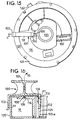
- FIG. 16 a cut-away view of FIG. 15 taken at line E-E is shown.
- the nonreplaceable lock 100 is mounted on rotor cover 116.
- Securement tab 102 is inserted in slot 105 and is retained therein via a friction fit.
- Slot 105 includes angled wall 105a which causes the securement tab 102 to compress as it is fully inserted within the slot 105.
- Stop tab 103 protrudes from the nonreplaceable lock 100 at the opposite side from the securement tab 102.
- the stop tab 103 is parallel to sidewall 114 of housing 120.
- the housing 120 and the rotor cover 116 form chamber 118 in which the conductor cable of the clockspring resides.
- the channel 105 is integrally molded with the rotor cover 116 and includes a ramp 106.
- the ramp allows for easy insertion of the insertion tab 102 into the slot 105.
- the nonreplaceable lock 100 also includes knob 108 which is frictionally fit in a crevice 109 of the rotor cover 116.
- the knob 108 provides for a second point of attachment of the nonreplaceable lock 100 so that it does not flap around or rock back and forth on the axis of the securement tab 102. It should be noted, however, that the friction fit of the securement tab 102 in slot 105 is much greater than the friction fit of the nub 108 in crevice 109.
- the clockspring may be assembled to a steering assembly. Such final assembly may require rotation of the rotor housing 116. As discussed above, in a preferred embodiment 180° of rotation is allowed by the nonreplaceable lock 100. During this rotation, the housing 120 is stationary while the rotor cover 116 rotates. This rotation is also transferred to the nonreplaceable lock 100 and the stop tab 103 will move along wall 114 in the direction of the rotation. The stop tab 103 will abut lip 121 at one limit of rotation and protrusion 122 at the other limit of rotation. Once the clockspring is completely assembled to the steering assembly, the nonreplaceable lock 100 may then be removed.
- the nonreplaceable lock 100 By grasping the gripping member 101 of the nonreplaceable lock 100, the nonreplaceable lock 100 may be rotated upwardly and toward the center of the clockspring in direction of arrow 110. This is caused by removing nub 108 from crevice 109.
- the securement tab 102 has a bite 111 which forms a pivot point 113.
- the nonreplaceable lock 100 will pivot at pivot point 113 and be rocked towards aperture 120 of the clockspring so that the gripping member 101 is moved 90° from its initial position shown in FIG. 16 so that it is perpendicular to the top of the rotor cover 116.
- the nonreplaceable lock 100 may be removed from the clockspring by tearing the polymer material at pivot point 113, leaving the base portion of securement member 102 in the slot 105. As the securement tab 102 has been separated into two sections, the nonreplaceable lock 100 can not be replaced on the clockspring. This method of having the nonreplaceable lock 100 on the top surface of the clockspring easily allows an inspector to see that the nonreplaceable lock 100 has been removed. This should signal that the assembly of the clockspring to the steering assembly has been completed. Removal of the nonreplaceable lock 100 before initial assembly of the clockspring to a steering column will alert inspectors that the clockspring may be uncentered and should be discarded.
Landscapes
- Engineering & Computer Science (AREA)
- Mechanical Engineering (AREA)
- Steering Controls (AREA)
- Coupling Device And Connection With Printed Circuit (AREA)
- Rotary Switch, Piano Key Switch, And Lever Switch (AREA)
- Lock And Its Accessories (AREA)
- Installation Of Indoor Wiring (AREA)
- Electric Cable Arrangement Between Relatively Moving Parts (AREA)
Abstract
Description
- The invention pertains to a clockspring interconnector for enclosing an electrical conductor cable, the clockspring interconnector electrically connecting a rotatable electric device with a stationary electric device.
- An increasing number of automobiles have air bag crash systems. An air bag is typically located on the steering wheel facing the driver. The air bag must be in continuous electrical connection with sensors in the car body. The sensors provide an electrical signal to the air bag crash assembly which instantly inflates the air bag in the event of a crash.
- Accordingly, there is a need for an electrical connection between the rotatable portion of the air bag assembly which is mounted to the steering wheel, and the remaining portion of the assembly, which is in a stationary position in the car body. Electrical connections between rotatable and stationary parts are well known. Typically, an electrical brush rests upon a conductive ring, with one of the parts being rotatable to provide such rotatable electrical connection. However, there is a risk, particularly during the impact of an accident, of a transient failure of electrical connection with a brush and ring system, which would result in failure of the entire air bag system crash assembly.
- Accordingly, a clockspring interconnector has been previously developed, comprising an outer housing, a rotor member and multiple intermediate housing members for enclosing and connecting the members; the housing and rotor member rotatably associated with one another at a plurality of bearing surfaces. A "clockspring" is located inside the interconnector. The clockspring is a flat conductor cable and has two ends conductively attached to conductor wires which pass out of the interconnector to unite the air bag to the sensing device. The interconnector is mounted on the steering column, and the steering wheel may be rotated in either direction while a continuous, positive electrical connection is provided between air bag sensors via the clockspring interconnector.
- While prior art clockspring interconnectors are effective to provide the necessary continuous electrical connection between an air bag or other device on a rotating column and a stationary portion of a circuit, the prior art systems were sometimes wound completely tight before the device was installed making the installed device useless. This problem was partially solved by providing a clockspring assembly with a device that kept the clockspring interconnector from rotating prior to installation.
- Such a locking mechanism was described in U.S. Patent No. 4,722,690. That patent describes a clockspring interconnector which includes a projection which engages a noncircular aperture of the rotor member to prevent the rotor member from rotating. This projection was removable by hand by reaching into the center aperture of the clockspring. This design is disadvantageous in that it requires a center aperture which is noncircular and also requires exposure of the center aperture on the clockspring so that an operator may grasp the projection for removal. In certain assembly operations of the clockspring to the steering wheel and steering column, it is sometimes impossible to remove such a locking projection which may become enclosed by a steering wheel housing or steering column housing. Thus, there is a need for a removable external locking means which may be exposed after assembly of the clockspring with a steering wheel housing and steering column housing. Such prior art locking mechanisms also required an additional locking mechanism to lock the steering column assembly prior to assembly of the clockspring assembly. Such an improved external locking means providing exposure after assembly could also eliminate the extra part for the steering column locking mechanism.
- U.S. Patent No. 5,171,157, describes a clockspring interconnector including spring-loaded locking pegs integral to the internal hub of the rotor. This patent describes locking pegs which may be depressed only upon engagement from above, providing direct vertical force onto the locking pegs. Such a design requires that a column being inserted through the center of such a clockspring have protruding portions which will project perpendicular to the path of insertion of the column into the clockspring and provide surfaces which will engage the locking pegs in a vertical direction. Such a system is disadvantageous because the hub being inserted into such a clockspring must be specially designed so that the protruding portions of the hub engage the locking pegs while still allowing complete mating insertion of the column through the clockspring and with the steering assembly. Accordingly, it is desired to have a locking means which may be engaged without the need of a specially design column.
- U.S. Patent No. 5,059,134, describes a connection location where the electrical conductors of the flat ribbon cable are serially connected to a connection conductor wires via the engagement of the uninsulated end portions of conductor wires against a clamping body which is surrounded by a protective sheath injection molded about the clamping body. This arrangement is both difficult and costly to assemble. In order to position the clamping body against the conductor wires and then injection mold the protective sheath about the clamping body, requires that this operation be done separately from the assembly of the flat cable within the clockspring housing. Accordingly, an improved structure is desired which allows for the simple, inexpensive and quick attachment of external conductor wires to the electrical conductors of the flat cable so that all assembly of the clockspring may occur prior to the attachment of the external cables.
- Generally, clocksprings have been known to have been assembled having at least three components. U.S. Patent No. 4,607,898, describes a clockspring having a first half and a second half which is a assembled by a face plate. The assembly of the clockspring having three or more parts is disadvantageous due to the need to manufacture and then assemble the multiple parts which is costly and time-consuming and the increased number of bearing surfaces which create noise. Accordingly, there is desired a clockspring which has only two parts and a single bearing surface and may be assembled together quickly and easily. Such an assembly including all of the above described advantages is possible by incorporating the structures of the present invention either in a single clockspring assembly or as individual components of separate clockspring assemblies.
- It is an object of the present invention to overcome all of the disadvantages of the prior art clocksprings by incorporating a clockspring structure which provides a design which is quickly and inexpensively assembled.
- It is another object of the present invention to provide a clockspring assembly which is immobile until it is attached to a standard steering column.
- It is a further object of this invention to provide a clockspring assembly that becomes immobile once it is disengaged from a standard steering column shaft.
- It is yet another object of this invention to provide a clockspring assembly which remains immobile after assembly to a steering column but after adjustments to the steering column are made and without disassembling the clockspring from within a steering housing and steering wheel, the clockspring may be mobilized.
- It is a further object of the present invention to provide a two-piece clockspring which may be assembled quickly and easily.
- It is another object of the present invention to provide a clockspring structure which allows for the complete assembly of the clockspring prior to attachment of external cables.
- It is yet another object of the present invention to provide for a clockspring assembly which allows for the quick and easy attachment of external cables at the conclusion of the assembly of the clockspring itself.
- The above objects and advantages are provided by a clockspring interconnector comprising a housing defining a chamber extending therethrough and a rotor cover attached to the housing. A coiled flat cable carried within the chamber surrounding the rotor cover. The flat cable having a first end attached to a first connector location of the rotor cover and a second end attached to a second connector location of the housing.
- The rotor cover defines a central aperture having a top opening and a bottom opening. The external diameter of the aperture having integral flanges extending from the rotor cover adjacent to the bottom opening. The housing having a center hole having a rim at its external diameter. The flanges having angled surfaces to slide past the rim and a protruding surface to engage the rim of the housing and secure the rotor cover thereto.
- The first and second end of the flat cable including a backbone to receive the end of the flat cable. The backbone protrudes from the rotor cover at a first connection location. The backbone protrudes from the housing at a second connection location. The backbone including parallel channels for positioning the conductors of the flat cable. The channels of the backbone are separated by ribs and positioning ribs. The ribs are adjacent to the conductors of the flat ribbon cable. The positioning ribs receive insulated wires having uninsulated end portions. The positioning ribs engaging the wires at an insulated portion. The wires being press fit between the positioning ribs and aligned with the conductors of the flat cable. The positioning ribs are heat staked sufficiently to deform the positioning ribs to trap the wire within the channels. The uninsulated end portion of the wire is welded to the conductors of the flat cable. A backbone cover is attached to the backbone. The backbone includes a gap running transverse to the channels. The backbone cover includes a rib. Upon attachment of the backbone cover to the backbone having the insulated wire inserted therein, the rib engages the insulated portion of the wire, pushing the wire into the gap. The backbone cover is secured to the backbone by placement of a rivet through the backbone cover and the backbone.
- An automatic unlocking means is included in the rotor cover. The unlocking means includes a depressed or unlocked position and an undepressed or locked position. The locking device includes a compression spring which urges the locking assembly having a detente to engage a recess along the rim of the housing. Upon assembly of the clockspring onto a steering column, the unlocking means is depressed, disengaging the detente of the locking means from the recess of the housing allowing the rotor cover to rotate.
- A locking means is provided having a latching body seated within a channel of the housing. A stop head protrudes from the latching body. The stop head engages a stop wing of the rotor top. The stop wing includes a neck portion. A narrow neck portion of the stop wing allows for rotation of the rotor cover in 350° and upon abutment of the stop head against the neck portion of the stop wing, the rotor cover is prohibited from making a full rotation. A pull tab is connected to the latching body and protrudes perpendicular to the sidewall of the housing. The pull tab includes an arm of sufficient length to allow for the pull tab to protrude sufficiently to be gripped subsequent to the assembly of the clockspring within a steering wheel housing and steering column housing. Pulling on the pull tab with sufficient force disengages the latching body from the channel of the housing and removes the stop head from its position, allowing the free rotation of the stop wing and rotor cover.
- A further embodiment of the present invention includes a nonreplaceable locking means preventing the rotation of the rotor cover more than 180°. The nonreplaceable locking means having a securement tab which remains within a slot of the clockspring after removal of the nonreplaceable locking means. The nonreplaceable locking means attached to the rotor cover. The clockspring interconnector comprising a lip protruding from the housing. A projection protruding from the housing a specified distance from the lip. A stop tab attached to the nonreplaceable locking means which will abut the lip when rotated in a first direction and the projection when rotated in a second direction. The clockspring interconnector includes a gripping member attached to the nonreplaceable locking means. The gripping member, the stop tab and the securement tab are integrally connected. The securement tab includes a means for separation of the securement tab from the nonreplaceable locking means. The means for separating the securement tab includes a bite for allowing the ripping separation of the nonreplaceable locking means from the securement tab. Removal of the nonreplaceable locking means allows the rotor cover to rotate more than 180°.
- These and other features of the invention are set forth below in the following detailed description of the presently preferred embodiments.
-
- FIG. 1 is a perspective view of a clockspring;
- FIG. 2 is a side view of FIG. 1;
- FIG. 3 is a top view of FIG. 1;
- FIG. 4 is a cut-away, side elevation view of FIG. 3 taken at line A-A;
- FIG. 5 is a bottom view of FIG. 1;
- FIG. 6 is a cut-away, side elevation view of FIG. 5 taken at line B-B;
- FIG. 7 is an end view of a backbone cover;
- FIG. 8 is a side elevation view of a backbone cover;
- FIG. 9 is a top view of a backbone;
- FIG. 10 is an end view of an assembled backbone;
- FIG. 11 is an enlarged top view of an assembled backbone;
- FIG. 12 is a cut-away, side elevation of FIG. 3 taken at line D-D;
- FIG. 13 is a cut-away, side elevation view of FIG. 3 taken at line C-C;
- FIG. 14 is a cut-away, side elevation cut-away view of FIG. 3 taken at line C-C;
- FIG. 15 is a top view of an alternative embodiment of a clockspring; and
- FIG. 16 is an enlarged cut-away side elevation view of FIG. 15 taken at line E-E.
- The clockspring interconnector of this invention is better understood by references to FIGS. 1-14 which shows various aspects of a presently preferred clockspring interconnector. Turning to FIG. 1, the clockspring 10 includes a
housing 12 having asidewall 14. Enclosing the top of thehousing 12 is therotor cover 16. Therotor cover 16 combines the separate prior art components of a rotor and a cover into a single integral component. Therotor cover 16 includes flanges (not shown) which allow therotor cover 16 to snap-fit onto thehousing 12. Thus, the main components of the clockspring 10 are only the rotor cover and thehousing 12. There are no other members needed to enclose thechamber 18 of thehousing 12 and no other parts needed to hold the clockspring 10 together. This two-piece design minimizes costs by having only the two parts and the two components are quickly and easily assembled, saving in labor, storage and tooling costs. The unique design also includes a single bearing surface at the attachment means of the flanges because the top 17 of therotor cover 16 is separated from thehousing 12 by agap 15 and does not bear together in this area. - The
rotor cover 16 includes anaperture 20 having atop opening 21 and abottom opening 22. The aperture includes aninner wall 24. Along the circumference of theinner wall 24 of therotor cover 16 resides an automatic unlocking means 30 to provide for the unlocking of therotor cover 16 allowing it to rotate freely on thehousing 12. The automatic unlockingmeans 30 includes abutton 35 having a slidingsurface 31 and is received incell 32. Thebutton 35 is shown in its undepressed, locked position prior to assembly of the clockspring 10 to a steering assembly. Upon assembly to a steering assembly and insertion of section of steering wheel throughaperture 20 of therotor cover 16, the steering wheel will engage slidingsurface 31 and force thebutton 35 to move in the direction ofarrow 33, transverse to the direction of insertion of the steering wheel. Movement of thebutton 35 in direction ofarrow 33 causes thebutton 35 to recede into thecell 32 causing thefront surface 34 to become flush with theinner wall 24 ofaperture 20. The movement of thebutton 35 in direction ofarrow 33 also causes a detente (not shown) ofbutton 35 to disengage from a recess of thehousing 12 and allow for therotor cover 16 to rotate freely from thehousing 12. - This arrangement of the automatic unlocking
means 30 allows for the shipping of the clockspring while it is in its locked position and prohibits the flat cable in thechamber 18 of thehousing 12 from unwinding during shipping and causing the disalignment of therotor cover 16 from thehousing 12. In the assembled state of the clockspring with a steering mechanism, it is essential that the clockspring have at least two and a half turns in each direction. Thus, it is necessary that when the clockspring is assembled to the steering mechanism that it be centered. This ensures that there be enough turns necessary for the proper functioning of the clockspring. Failure to provide the assembly of a properly centered clockspring may cause the locking of the rotor cover or rupture of the flat cable of the clockspring when turned too far in one direction. In a preferred embodiment, the unlocking means 30 slidably engages and disengages in a direction transverse to the direction of the insertion of the steering wheel assembly. The unlocking means 30 also allows for the removal of the clockspring from the steering assembly for repairs while prohibiting the unwinding or uncentering of therotor cover 16 in relation to thehousing 12. Thus a repair worker may simply remove the clockspring 10 from the steering assembly which will cause thebutton 35 to disengage fromcell 32 and its detente will engage the recess of thehousing 12. This automatic unlockingmeans 30 ensures therotor cover 16 is centered on thehousing 12 at all times when the clockspring 10 is disassembled. - While the automatic unlocking
means 30 provides for a means of preventing rotation throughout the life of the clockspring, a more temporary mechanism is the locking means 40. This locking means 40 must be manually removed and provides for locking of the clockspring 10 even after assembly to a steering assembly, when the unlockingmeans 30 is depressed and unlocked. However, this locking means 40 will be discussed in a separate context from the automatic unlocking means 30 in that it will be assumed that they will function independently of the other unless stated otherwise. The locking means 40 includes a latchingbody 41 which is seated within achannel 42 which is formed along theouter wall 14 of thehousing 12. The locking means 40 is seated within thechannel 42 by frictional engagement of abase portion 43 of the latching body to engage asill 44 of thechannel 42. Integral with the latchingbody 41 is astop head 45 which protrudes above the plane of therotor cover 16. Thestop head 45 is oriented to engage astop wing 48 integral with therotor cover 16. Thestop wing 48 includes aneck portion 49. Upon rotation of therotor cover 16 in a counterclockwise direction, theneck portion 49 of thestop wing 48 will abut thestop head 45 of the locking means 40. Therotor cover 16 may also be rotated in the clockwise direction. However, therotor cover 16 will be prohibited from making a full rotation in that theneck portion 49 of thestop wing 48 will abut the other side of thestop head 45 and inhibit further rotation. In a preferred embodiment of the invention, theneck portion 49 is sufficiently wide so that rotation is limited to 350°. The enlargement of the widths of theneck portion 49 decreases the amount of rotation that is allowed by therotor cover 16. Inversely, the decreasing ofneck portion 49 of thestop wing 48 will increase the degree of rotation that is allowed by therotor cover 16. For example, another embodiment of this invention could provide aneck portion 49 which protrudes around 180° of therotor cover 16. Thus, the rotor cover would only be allowed to rotate 180° before abutting theneck portion 49 ofstop wing 48. - The amount of rotation necessary depends upon the assembly procedures required. In a preferred embodiment, the clockspring 10 is assembled onto a steering assembly in which the
rotor cover 16 is enclosed in a steering wheel housing and the lower portion of thehousing 12 is enclosed in a steering column housing. However, even after assembly of the clockspring 10 to a steering assembly, further assembly is required in some circumstances of the steering column to the drive mechanism. This assembly may require rotation of the steering column and in turn, the steering wheel assembly. In order to assemble a number of parts of the steering column, large degrees of rotation may be required for the easy assembly thereof. However, during this assembly, it is still essential that the clockspring remain centered. During such assembly of the steering column, it is possible that without a proper locking mechanism that the clockspring will become uncentered and be turned too far in one direction so that when the steering column mechanism is finally and completely attached, the clockspring will be out of alignment. As well, if the clockspring 10 includes an automatic unlockingmeans 30, as discussed above, the assembly of the clockspring will unlock the automatic locking means and allow full rotation of therotor cover 16 upon thehousing 12. In such a case, upon conclusion of the assembly and at operation of the steering wheel, it is likely that a turn in one direction will break the flat cable, while turning in the other direction would allow rotation well beyond two and a half turns. Thus, the engagement of a thestop head 45 against theneck portion 49 of thestop wing 48 while prohibiting rotation of therotor cover 16 beyond 360°, does allow for limited motion of the clockspring and steering assembly to which it is attached for the proper assembly of the steering column. Following such assembly and returning of the steering wheel to its centered position, the locking means 40 may then be removed. The above advantages are realized for the locking means 40 of a clockspring having both a locking means 40 and an automatic unlockingmeans 30 only where the steering mechanism is assembled after the clockspring is assembled to the steering column. -
Pull tab 46 is provided which protrudes perpendicular from theside wall 14 of thehousing 12. Thepull tab 46 is positioned vertically on theside wall 14 so that it protrudes from a gap which exists when a steering wheel housing is assembled above it and a steering column housing is assembled below it. The length of thearm 47 of thepull tab 46 is dependent upon the overhang that the steering wheel housing and the steering column housing protrude from the clockspring 10. Thepull tab 46 includes grippingportion 78 which allows for easy pulling of thepull tab 46 and removal of the locking means 40 from thechannel 42. Whilefinger 49 maintains the latchingbody 41 of the locking means 40 within thechannel 42, upon pulling on thepull tab 46, thebase portion 43 of the latching body will ride over thefinger 49 and allow removal from thechannel 42. Upon pulling of thepull tab 46, thestop head 45 will slide down theside wall 14 of the housing and follow the pull tab out and from between the gap created between the steering wheel housing and the steering column housing. Having removed the locking means 40, the clockspring 10 will be able to rotate freely. Once the locking means 40 is disengaged, it cannot be replaced withinchannel 42 and only provides a temporary locking feature. - The
housing 12 defineschamber 18 which houses the flat cable. The flat cable is wound around theinner wall 24 of therotor cover 16. The flat cable has a first end and a second end. In a preferred embodiment, the first end is connected to therotor cover 16 at afirst connection location 50. Thefirst connection location 50 includes abackbone 51 which is inserted throughpassage 58 and protrudes beyond the top surface of therotor cover 16. Thefirst connection location 50 secures the conductors of the flat cable in an accessible orientation on thebackbone 51. Upon complete assembly of the clockspring 10,external cables backbone 51. Theexternal cables squib connector 62 which connects to an igniter which activates the air bag.The second end of the flat cable is terminated at asecond connection location 55 having a similar construction to the first connection location and havingexternal wires 63 attached thereto which may attach to a sensing device or power source within the engine compartment of an automobile. - Turning to FIG. 2, a side elevation of the clockspring 10 of FIG. 1 is shown. The
top rotor cover 16 is shown attached to thehousing 12. It can be seen that there is agap 15 which is present between thehousing 12 and therotor cover 16. Assembly of the clockspring 10 having thegap 15 allows for rotation of therotor cover 16 on thehousing 12 without having a surface for rubbing which may cause excessive noise or friction. Thegap 15 reduces greatly the amount of bearing surfaces and provides for a much easier rotation of the clockspring 10.First connection location 50 is shown havingbackbone 51 enclosed bybackbone cover 52 and havingwires 53 leaving therefrom. Alip 54 is shown which is formed integral with therotor cover 16 and provides for a surface for thebackbone cover 52 to slide into for securement around thebackbone 51. Locking means 40 is shown having latchingbody 41 and stophead 45.Second connection location 55 is shown where the second end of the flat cable is terminated. Integrally formed with thehousing 12 are snap legs 11 which provide for the snap mounting of the housing to a steering column housing. Locator pegs 13 also help mount thehousing 12 to a steering column housing. - Turning to FIG. 3, a top view of a clockspring 10 is shown.
Rotor cover 16 includesaperture 20. Therotor cover 16 has formed thereon thefirst connection location 50 and the automatic unlockingmeans 30. Locking means 40 is shown attached tohousing 12. Thestop wing 48 is integrally formed with therotor cover 16 to engagestop head 45. - Turning to FIG. 4 a cut-away, side elevation view of FIG. 3 taken at line A-A is shown. In a preferred embodiment,
rotor cover 16 is assembled directly to thehousing 12. The housing defines achamber 18 in which the flat cable (not shown) is housed. The rotor cover 16 forms anaperture 20. Theaperture 20 includes atop opening 21 and abottom opening 22. Therotor cover 16 includes a top 17 and integral thereto aninner wall 24. Theinner wall 24 at its exterior surface defines theaperture 20 and on its interior surface provides the rotor which the clockspring is wound about. Integral to theinner wall 24 areflanges 25. - The
housing 12 includes acenter hole 26 into which theinner wall 24 andaperture 20 of therotor cover 16 is inserted. Protruding from thecenter hole 26 of thehousing 12 is arim 27. The engagement of theflanges 25 of therotor cover 16 with therim 27 of thehousing 12 provides for the attachment of the rotor cover to thehousing 12. Theflanges 25 includeangled surfaces 28 and protruding surfaces 29. Therotor cover 16 is formed of a polymer material which is hard but flexible. Upon insertion of the flanges intocenter hole 26 of the housing, theangled surface 28 of theflanges 25 of therotor cover 16 abut the upper surface of therim 27. The flanges are stressed inwardly and slide past therim 27. Upon full insertion of the flanges into the center hole of thehousing 12, the flanges snap outwardly engaging protruding surface 29 underrim 27. In a preferred embodiment, eight flanges are present around the bottom opening 22 of therotor cover 16 providing engagement points at each 45° position around therim 27 of thehousing 12. Such an assembly provides for the permanent connecting of therotor cover 16 to thehousing 12 and also allows for the smooth rotation of therotor cover 16 on thehousing 12. However, as few as four flanges may provide such functions as well.Shoulders 31 of therotor cover 16 provide for a tight fit and eliminate any wobbling upon mating of therotor cover 16 with thehousing 12. Theshoulder 31 of therotor cover 16 and rim 27 of thehousing 12 are the only bearing surfaces of the present invention providing for low noise upon rotation of therotor cover 16 against thehousing 12. - Within the
chamber 18 of thehousing 12 are included insulatingmaterial 70. This insulatingmaterial 70 provides for a surface of the flat cable to rub against. Upon rotation of therotor cover 16 and movement of the flat cable, the rubbing and noise created by the rotation of the flat cable will be reduced. In a preferred embodiment, the insulating material is a mat finished vinyl foam tape (Great Lakes Tape & Label, Inc.) having a cellular, flexible polyvinyl chloride (CH₂-CHCL)n foam composition. The vinyl foam tape includes an acrylic adhesive on one side so that it may easily be attached to the housing. Such insulation may also be attached to theunderside 71 of therotor cover 16. The sound dampening that the insulating material provides is partly due to the rough surface of the insulatingmaterial 70 which the flat cable rubs against. Also,first connection location 50 andsecond connection location 55 are shown. - FIG. 5 discloses a bottom view of the clockspring of FIG. 1.
Housing 12 is shown havingcenter hole 26. Thebottom opening 22 of theaperture 20 of the rotor cover havingintegral flanges 25 snapped over therim 27 of thehousing 12.Second connection location 55 is shown. - Turning to FIG. 6, a cut-away, side elevation view of the second connection location taken at line B-B of FIG. 5 is shown. FIGS. 6-11 all show a preferred embodiment of a wire harness connector which terminates the end of the flat ribbon cable and allows for easy and quick attachment of external cables at the connection locations. The discussion of FIGS. 6-11 and the
second connection location 55 also equally apply to the structure of thefirst connection location 50 and such structure can be interchanged at both locations.Second connection location 55 is located at the base ofhousing 12 adjacent to sidewall 14. The top 17 ofrotor cover 16 is shown above thehousing 12. Thehousing 12 forms achamber 18 in which the flat conductor cable is wound around the inner wall of therotor cover 16. The flat cable includes a first end terminating at the first connection location at the rotor cover and a second end terminating at the second connection location at thehousing 12. - The
second connection location 55 consists of abackbone 51. In a preferred embodiment, thebackbone 51 includes afirst side 63 and asecond side 64. The second end portion of theflat ribbon cable 65 is received at thefirst side 63 of thebackbone 51. Theend portion 65 of the flat ribbon cable approaches thebackbone 51 from a transverse direction. It meets thebackbone 51 at thefirst side 63 and is then folded around thebackbone 51 onto thesecond side 64 of thebackbone 51. Theflat cable 56 is then folded down at an angle to form a change in the longitudinal direction of theflat cable 56 of approximately 90° so that theend portion 56 of the flat cable is travelling parallel to the direction of thebackbone 51. - Extending from the
end portion 56 of the flat ribbon cable areelectrical conductors 57 which are uninsulated and extend from the latex coating of the end portion of theflat cable 56. Theconductors 57 are carried within channels of thebackbone 51. The backbone includes pins to retain and hold the flat cable in place. The steps of securement of the flat ribbon cable to the backbone in order to terminate the flat ribbon cable are all that occur during the assembly of the clockspring 10. The simple and quick procedure of terminating the flat cable to the backbone as described above and inserting the backbone into thepassage 58 of the housing are all the assembly required. The further assembly of the clockspring may occur without having to attach exterior cables to the clockspring. Thus, the clockspring 10 may be handled easily and quickly without having the excess and cumbersome external wires and harnesses inhibiting the quick handling of the clockspring 10 on an assembly line. As the harness assembly is also a complicated and timely process, it is helpful to be able to complete such an assembly separate from the clockspring and also have the advantages of completing these assemblies without having the clockspring attached thereto, causing the cumbersome and timely handling. Simply by terminating the flat cable to thebackbone 51 and having the backbone protrude from the housing exposing theconductors 57 for future attachment of exterior cables is a great cost saving measure. - Upon complete assembly of the clockspring 10 and assembly of the
rotor cover 16 to thehousing 12, the exterior cables may then be attached. The exposedconductors 57 of the flat cable are attached quickly and easily to external cables by feeding theinsulated wires 53 into the channels of thebackbone 51. Ribs between the channels guide the insulated portions of thewires 53 into the channels. Theuninsulated wires 62 are placed adjacent to theconductors 57. Thewires 53 are then secured to thebackbone 51 and theuninsulated wires 62 are soldered to theconductor 57 as will be described in more detail below. Abackbone cover 52 is attached to thebackbone 51 to protect the terminated conductor and attachedwires 53. The backbone cover 52 also includes arib 66 which engages theinsulated wires 53 atpoint 81. Therib 66 forces theinsulated wires 53 intogap 76 and deforms theinsulated wires 53 with four bends of 90°. The engagement of therib 66 with the insulated wire provides a strain relief means to inhibit theinsulated wires 53 from being pulled from thebackbone 51. - Turning to FIG. 7, the
backbone cover 52 is shown havingrib 66. The backbone cover 52 slides over the backbone and therib 66 abuts and compresses the insulated wires to provide a strain relief mechanism. FIG. 8 is a side elevation view of thebackbone cover 52 havingrib 66. - Turning to FIG. 9, the
backbone 51 is shown having itssecond side 64 exposed. Anend portion 65 of the flat ribbon cable is inserted at afirst side 63 of thebackbone 51. The flat ribbon cable is placed onto thebackbone 51 at thefirst side 63 at an angle transverse to the length of thebackbone 51. Theflat cable 65 is folded around thebackbone 51 onto thesecond side 65 at afirst fold 67. Asecond fold 68 is made at an angle in which theend portion 56 of the flat cable is folded over on itself and redirects the flat ribbon cable in a 90° turn so that theend portion 56 is then directed parallel to the length of thebackbone 51. -
Channels 71 are integrally molded into thesecond side 64 of thebackbone 51. Theconductors 57 of theflat cable 56 are inserted into thechannels 71. The flat cable is retained on thebackbone 51 viapins 73 which protrude from the sides of the backbone and under which theflat cable flat cable pins 73 of thebackbone 51 and the folding of the flat cable atfirst fold 67 andsecond fold 68, the flat cable becomes securedly attached to thebackbone 51. This assembly of the flat cable terminated onto the backbone is all that is required for the assembly of the clockspring itself. The assembled backbone may then be inserted into thepassage 58 of thehousing 12. The use of thebackbone 51 allows for the simple termination of theflat cable - The
backbone 51 includeschannels 71 which are separated byribs 75. Agroove 76 is also integrally molded into thebackbone 51 and provides for an area into which the insulated wires may be depressed upon attachment of the backbone cover. Positioningribs 77 are located at the end of thebackbone 51 and are of a sufficient width so that an insulated wire (not shown) may be press fit between thepositioning ribs 77. Thesepositioning ribs 77 will also be melted by contact with a heat stake to secure the inserted wires in thechannels 71. - FIG. 10 is an end view of a completely assembled
backbone 51 havingconductors 57 attached touninsulated wires 62. Turning to FIG. 11, a top view of a completely assembledbackbone 51 is shown having aflat cable 56 withuninsulated conductors 57 protruding from theflat cable 56 intochannels 71. After a clockspring is completely assembled, theexternal harness 60 will be attached to the clockspring by aligning the individualinsulated wires 53 in thechannels 71. Theinsulated wires 53 are inserted between theribs 75 andpositioning ribs 77 and theuninsulated wires 80 are aligned with theconductors 57 of theflat cable 56. The insulated wires are press fit between thepositioning ribs 77 and are held in place to thebackbone 51 therein. Thepositioning ribs 77 are then melted by contact with a heat stake which forms a homogeneous layer above theinsulated wires 53, closing the opening above theinsulated wires 53 adjacent thepositioning ribs 77 and securing the wires within thechannels 71. - In a preferred method of attaching the
wires 53 to theconductors 57 of theflat cable 56, theuninsulated wires 80 are ultrasonically welded to theconductors 57. Abackbone cover 52 is then slid over thebackbone 51 to protect the terminated and connected ends of the conductors and wires. Thebackbone cover 52 includes arib 66 which abuts theinsulated wires 53 atarea 81 and compresses the wire intogroove 76 causing theinsulated wire 53 to deform as shown in FIG. 6. Because the engagement of therib 66 against thewires 53 occurs at the insulated area of thewire 53, a strain relief function is created. Thebackbone cover 52 is secured to thebackbone 51 by any means. In a preferred embodiment, a rivet is used to secure the backbone cover. It is anticipated by this invention that the specific termination means and method described herein is only by way of an example and other specific components and methods are also covered. - Turning to FIG. 12, a side elevation cut-away view taken at line D-D of FIG. 3 is shown. The clockspring 10 includes the
rotor cover 16 andhousing 12. The locking means 40 is shown protruding from a clockspring 10 assembled within asteering wheel housing 85 and asteering column housing 86. The locking means 40 haspull tab 46 protruding perpendicularly from thehousing 12 at apoint 87 along thesidewall 14 of thehousing 12 which is specifically oriented to be below thesteering wheel housing 85 and above thesteering column housing 86. Upon assembly of the clockspring within thesehousings gap 90 is formed through which thepull tab 46 protrudes. Thepull tab 46 is integrally connected to the latchingbody 41 which is seated withinchannel 42. Astop head 45 is integral to the latchingbody 41 protrudes beyond the plane of therotor cover 16. Astop wing 48 engages thestop head 45 and limits therotor cover 16 from rotating beyond 350°. - Turning to FIG. 13, the automatic unlocking
means 30 is shown. The unlocking means 30 is shown in its undepressed locked position. The drawing shows a cut-away, side elevation view of FIG. 3 taken at line C-C. Abutton 35 includes a slidingsurface 31 and adetente 36. Thebutton 35 is positioned adjacent to thebottom opening 22 of therotor cover 16 and withincell 32.U-shaped spring member 38 forces thebutton 35 towards thecenter 39 of the clockspring 10. Thespring member 38 abuts tab 91 which retains thespring member 38 andbutton 35 withincell 32. In its locked position, thedetente 36 is forced into arecess 37 of thehousing 12. The sides of thedetente 36 engage the inner walls of therecess 37 and prevent the rotation of therotor cover 16 in association with thehousing 12. In a preferred embodiment, thedetente 36 includes beveled edges engaging correspondingly tapered walls of therecess 37. The beveled edges ensure that thedetente 36 will not disengage from therecess 37. Further, the recess is widely spaced allowing gaps on either side of thedetente 36 so that even upon engagement of thedetente 36 withinrecess 37, minor rotation of 10° (5° in each direction) of therotor cover 16 is allowed. - Turning to FIG. 14, the
button 35 is shown in its depressed and unlocked position. Upon assembly of the clockspring 10 into a steering assembly, a steering wheel section (not shown) will be inserted into thetop opening 21 of therotor cover 16 in the direction ofarrow 90 and it will abut the slidingsurface 31 of thebutton 35. The further insertion of the steering wheel within the clockspring 10 will cause thebutton 35 to move away from thecenter 39 and the steering wheel section will slide along thefront surface 34 of thebutton 35, depressing thespring member 38 and moving the button intocell 32 anddetente 36 out ofrecess 37 of thehousing 12. The removal ofdetente 36 fromrecess 37 allows therotor cover 16 to rotate freely about thehousing 12. Thus, the assembly of the clockspring to a steering assembly engages the automatic unlockingmeans 31 allowing it to rotate freely. - Turning to FIG. 15, a top view of an alternative embodiment of the present invention is shown.
Rotor cover 116 includesaperture 120 and has formed thereon afirst connector location 150. An additional feature of anonreplaceable lock 100 includes grippingmember 101,securement tab 102 and stoptab 103. In a preferred embodiment, thenonreplaceable lock 100 is comprised of a polymer material such as minlon or hytrel.Securement tab 102 is inserted intoinsertion slot 105 which is formed as part of therotor cover 116. This alternative embodiment of a clockspring includes ahousing cover 120 which is stationary. Thehousing cover 120 includeslip 121 andprojection 122. Upon rotation of therotor cover 116, thenonreplaceable lock 100 is attached to therotor cover 116 and rotates with therotor cover 116. Rotation in a first direction or the counter-clockwise direction approximately 90° from the position shown in FIG. 15 causes stoptab 103 toabut lip 121 ofhousing cover 120. This abutment prohibits therotor cover 116 from rotating any further in the counter-clockwise direction. Rotation of therotor cover 116 in a second direction or the clockwise direction, approximately 90° from its position as shown in FIG. 15, causes stoptab 103 toabut projection 122. The abutment ofstop tab 103 againstprojection 122 prohibits therotor cover 116 from rotating any further in the clockwise direction. - Similar to the locking means 40, as shown in FIG. 12, the
nonreplaceable lock 100 provides a temporary locking means which allows limited rotation of therotor cover 116 to allow for necessary movement of the clockspring for final installation to a steering assembly while preventing the clockspring from becoming uncentered. In a preferred embodiment, thelip 121 andprojection 122 are oriented so that approximately 180° of rotation of therotor cover 116 is allowed so that final assembly of the clockspring to a steering column may be easily accomplished while insuring that the clockspring will remain centered. In a preferred embodiment, other locks may be present which prohibit rotation of the clockspring prior to initial assembly but are deactivated upon attachment of the clockspring to the steering column (see U.S. Patent No. 5,171,157), leaving the nonreplaceable lock to limit rotation following attachment of the clockspring to the steering column, but allowing for additional adjustments to the steering column during final assembly of the steering assembly. After final assembly of the clockspring to a steering assembly, thenonreplaceable lock 100 can be easily removed from the clockspring by grasping grippingmember 101 and removing thenonreplaceble lock 100. The grippingmember 101 will become separated from thesecurement tab 102 and cannot be replaced thereto. - Turning to FIG. 16, a cut-away view of FIG. 15 taken at line E-E is shown. The
nonreplaceable lock 100 is mounted onrotor cover 116.Securement tab 102 is inserted inslot 105 and is retained therein via a friction fit.Slot 105 includes angled wall 105a which causes thesecurement tab 102 to compress as it is fully inserted within theslot 105.Stop tab 103 protrudes from thenonreplaceable lock 100 at the opposite side from thesecurement tab 102. Thestop tab 103 is parallel to sidewall 114 ofhousing 120. Thehousing 120 and therotor cover 116 form chamber 118 in which the conductor cable of the clockspring resides. - The
channel 105 is integrally molded with therotor cover 116 and includes aramp 106. The ramp allows for easy insertion of theinsertion tab 102 into theslot 105. Thenonreplaceable lock 100 also includesknob 108 which is frictionally fit in acrevice 109 of therotor cover 116. Theknob 108 provides for a second point of attachment of thenonreplaceable lock 100 so that it does not flap around or rock back and forth on the axis of thesecurement tab 102. It should be noted, however, that the friction fit of thesecurement tab 102 inslot 105 is much greater than the friction fit of thenub 108 increvice 109. - Upon delivery of a clockspring having the
nonreplaceable lock 100 mounted thereon, the clockspring may be assembled to a steering assembly. Such final assembly may require rotation of therotor housing 116. As discussed above, in a preferred embodiment 180° of rotation is allowed by thenonreplaceable lock 100. During this rotation, thehousing 120 is stationary while therotor cover 116 rotates. This rotation is also transferred to thenonreplaceable lock 100 and thestop tab 103 will move along wall 114 in the direction of the rotation. Thestop tab 103 will abutlip 121 at one limit of rotation andprotrusion 122 at the other limit of rotation. Once the clockspring is completely assembled to the steering assembly, thenonreplaceable lock 100 may then be removed. By grasping the grippingmember 101 of thenonreplaceable lock 100, thenonreplaceable lock 100 may be rotated upwardly and toward the center of the clockspring in direction ofarrow 110. This is caused by removingnub 108 fromcrevice 109. Thesecurement tab 102 has abite 111 which forms apivot point 113. Thenonreplaceable lock 100 will pivot atpivot point 113 and be rocked towardsaperture 120 of the clockspring so that the grippingmember 101 is moved 90° from its initial position shown in FIG. 16 so that it is perpendicular to the top of therotor cover 116. Once rotated in this position, thenonreplaceable lock 100 may be removed from the clockspring by tearing the polymer material atpivot point 113, leaving the base portion ofsecurement member 102 in theslot 105. As thesecurement tab 102 has been separated into two sections, thenonreplaceable lock 100 can not be replaced on the clockspring. This method of having thenonreplaceable lock 100 on the top surface of the clockspring easily allows an inspector to see that thenonreplaceable lock 100 has been removed. This should signal that the assembly of the clockspring to the steering assembly has been completed. Removal of thenonreplaceable lock 100 before initial assembly of the clockspring to a steering column will alert inspectors that the clockspring may be uncentered and should be discarded. - From the foregoing, it will be observed that numerous variations and modifications may be effected without departing from the spirit and scope of the novel concept of the invention. It is to be understood that no limitation with respect to the specific apparatus illustrated herein is intended or should be inferred. It is, of course, intended to cover by the appended claims all such modifications as fall within the scope of the claims.
Claims (28)
- A clockspring interconnector comprising:
a housing defining a chamber;
a rotor cover attached to said housing;
a flat conductor cable coiled within said chamber having a first end and a second end;
said first end attached to said rotor cover;
said second end attached to said housing;
an aperture at the center of said rotor cover having a bottom opening; and
attachment means integral to said rotor cover adjacent to said bottom opening; and
attaching said rotor cover to said housing via a snap-fit of said attachment means over a rim of said housing. - The clockspring interconnector of Claim 1 wherein:
said attachment means includes flanges;
a rim adjacent said bottom opening; and
said flanges engaging said rim to attach said rotor cover to said housing. - The clockspring interconnector of Claim 1 wherein said chamber having on at least one surface an insulating material of vinyl foam tape.
- The clockspring interconnector of Claim 3 wherein said insulating material includes a cellular, flexible polyvinyl chloride foam composition.
- The clockspring interconnector of Claim 1 including:
uninsulated conductors extending from said flat cable; and
a connection location having said flat conductor cable attached thereto wherein said conductors of said flat cable are exposed beyond a plane of said rotor cover. - The clockspring interconnector of Claim 5 including:
a first connection location of said rotor cover having said first end of said flat cable attached thereto and a second connection location having said second end of said flat cable attached thereto. - The clockspring interconnector of Claim 5 wherein said connection location includes:
a backbone; and
said backbone having channels for receiving respective ones of said conductors and pins for mounting said flat cable thereto. - The clockspring interconnector of Claim 7 wherein said connection location includes a backbone cover having a strain relief means.
- The clockspring interconnector of Claim 1 wherein an automatic unlocking means provides the free rotation of said rotor cover upon insertion of a steering wheel assembly providing movement of said unlocking means transverse to the path of insertion of the steering wheel assembly.
- The clockspring interconnector of Claim 9 wherein said unlocking means includes a button having a depressed, unlocked position and an undepressed, locked position.
- The clockspring interconnector of Claim 10 including:
an inner wall of said rotor cover defining an aperture;
said button having a U-shaped spring member therein and a detente engaging a recess of said housing; and
said button slidable transversely to said inner wall. - The clockspring interconnector of Claim 1 including:
a locking means preventing the rotation of the rotor cover relative to the housing more than 350°, having a pull tab which is exposed following assembly of the clockspring to a steering assembly. - The clockspring interconnector of Claim 10 wherein:
said locking means includes a latching body seated within a channel of said housing;
a pull tab protruding perpendicular to said latching body;
a stop head protruding beyond the plane of the rotor cover and engaging a stop wing of the rotor cover; and
a gripping portion. - The clockspring interconnector of Claim 13 wherein said latching body, pull tab and stop head are integrally connected.
- The clockspring interconnector of Claim 14 wherein removal of said latching body by pulling on said pull tab allows said rotor cover to rotate beyond a single turn.
- The clockspring interconnector of Claim 1 wherein said attachment means is the only bearing surface between said rotor cover and said housing.
- A clockspring interconnector comprising a housing defining a chamber containing a coiled flat cable conductor having an end terminated by the method comprising the steps of:
inserting conductors of said flat cable in channels of a backbone;
inserting said backbone within a passage of said clockspring so that said backbone protrudes beyond the plane of said clockspring;
inserting insulated wires of external cables into said channels so that uninsulated end portions of said insulated wires are aligned with said conductors;
welding said uninsulated wires with said conductors;
covering said protruding portion of said backbone; and
securing said cover to said backbone. - The method of terminating a flat cable of Claim 17 including the step of melting retaining pegs over said insulated wires.
- The method of Claim 18 wherein said cover includes a rib to engage said insulated wire to provide strain relief through the wire upon attachment of said cover to said backbone.
- A clockspring connector comprising:
a housing defining a chamber;
a rotor cover attached to said housing;
a flat conductor cable coiled within said chamber having a first and a second end;
said first end attached to said first rotor cover;
said second end attached to said housing;
an aperture at the center of said rotor cover having a bottom opening;
an attachment means integral to said rotor cover adjacent to said bottom opening attaching said rotor cover to said housing;
uninsulated conductors extending from said flat cable;
a connection location having said flat conductor cable attached thereto wherein conductors of said flat cable are exposed beyond the plane of said rotor cover;
said connection location includes:
a backbone; and
said backbone having channels for receiving said conductors and pins for mounting said flat cable thereto. - A clockspring connector comprising:
a housing defining a chamber;
a rotor cover attached to said housing;
a flat conductor cable coiled within said chamber having a first and a second end;
said first end attached to said first rotor cover;
said second end attached to said housing; and
a nonreplaceable locking means preventing the rotation of the rotor cover more than 180°, having a securement tab which remains within a slot of the clockspring after removal of the nonreplaceable locking means. - The clockspring interconnector of Claim 21 wherein:
said nonreplaceable locking means is attached to said rotor cover. - The clockspring interconnector of Claim 22 comprising:
a lip protruding from said housing;
a projection protruding from said housing a specified distance from said lip; and
a stop tab attached to said nonreplaceable locking means which will abut said lip when rotated in a first direction and said projection when rotated in a second direction. - The clockpspring interconnector of Claim 23 comprising:
a gripping member attached to said nonreplaceable locking means. - The clockspring interconnector of Claim 24 wherein said gripping member, said stop tab and said securement tab are integrally connected.
- The clockspring interconnector of Claim 21 wherein said securement tab includes a means for separation of said securement tab from said nonreplaceable locking means.
- The clockspring interconnector of Claim 26 wherein said means for separating includes a bite for allowing the ripping separation of the nonreplaceable locking means from said securement tab.
- The clockspring interconnector of Claim 21 wherein removal of said nonreplaceable locking means allows said rotor cover to rotate more than 180°.
Applications Claiming Priority (4)
| Application Number | Priority Date | Filing Date | Title |
|---|---|---|---|
| US08/196,311 US5460535A (en) | 1994-02-14 | 1994-02-14 | Two-piece clockspring with lock and wire harness assembly |
| US196311 | 1994-02-14 | ||
| US08/285,021 US5429517A (en) | 1994-02-14 | 1994-08-02 | Two-piece clockspring with lock and wire harness assembly |
| US285021 | 1994-08-02 |
Publications (2)
| Publication Number | Publication Date |
|---|---|
| EP0667262A1 true EP0667262A1 (en) | 1995-08-16 |
| EP0667262B1 EP0667262B1 (en) | 1998-11-11 |
Family
ID=26891812
Family Applications (1)
| Application Number | Title | Priority Date | Filing Date |
|---|---|---|---|
| EP95300844A Expired - Lifetime EP0667262B1 (en) | 1994-02-14 | 1995-02-10 | Two-piece clockspring with lock and wire harness assembly |
Country Status (9)
| Country | Link |
|---|---|
| US (1) | US5429517A (en) |
| EP (1) | EP0667262B1 (en) |
| JP (1) | JP3558719B2 (en) |
| KR (1) | KR100352542B1 (en) |
| CN (1) | CN1045695C (en) |
| AT (1) | ATE173211T1 (en) |
| CA (1) | CA2142051C (en) |
| DE (1) | DE69505861T2 (en) |
| ES (1) | ES2123906T3 (en) |
Cited By (2)
| Publication number | Priority date | Publication date | Assignee | Title |
|---|---|---|---|---|
| EP2078647A2 (en) | 2008-01-10 | 2009-07-15 | Vola Plast Werner Hoppach KG | Washing assembly for screens and/or headlamps of a vehicle |
| WO2017093313A1 (en) * | 2015-12-02 | 2017-06-08 | Trw Automotive Safety Systems Gmbh | Cable conduit device for connection cables of an airbag module, wiring system, airbag module, and steering wheel or vehicle comprising a cable conduit device of said type |
Families Citing this family (38)
| Publication number | Priority date | Publication date | Assignee | Title |
|---|---|---|---|---|
| FR2710597B1 (en) * | 1993-10-01 | 1995-11-24 | Valeo Electronique | Rotating switch for motor vehicle. |
| KR0140588B1 (en) * | 1994-03-09 | 1998-07-01 | 가다오까 마사다까 | Rotating Connector |
| US6095836A (en) * | 1994-07-19 | 2000-08-01 | Methode Electronics, Inc. | Clockspring connector with carrier member |
| US6213797B1 (en) | 1994-07-19 | 2001-04-10 | Methode Electronics, Inc. | Clockspring having non-compliant and compliant roller members |
| US6012935A (en) * | 1994-07-19 | 2000-01-11 | Methode Electronics, Inc. | Clockspring connector with carrier member |
| US5601437A (en) * | 1994-10-17 | 1997-02-11 | Methode Electronics, Inc. | Clockspring with centering display device |
| JP3373966B2 (en) * | 1995-02-10 | 2003-02-04 | アルプス電気株式会社 | Rotating connector |
| US5810606A (en) * | 1995-06-07 | 1998-09-22 | Methode Electronics, Inc. | Articulating connector transmission system for signal data and power |
| JP3637120B2 (en) * | 1995-11-01 | 2005-04-13 | ナイルス株式会社 | Combination switch device with rotating connector |
| JP3273540B2 (en) * | 1996-02-07 | 2002-04-08 | アルプス電気株式会社 | Rotating connector mounting structure |
| US6841735B1 (en) * | 1996-04-03 | 2005-01-11 | Methode Electronics, Inc. | Flat cable and modular rotary anvil to make same |
| US5749744A (en) * | 1996-06-26 | 1998-05-12 | Henderson; Brent E. | Electrical connector with EMI/RFI shielding |
| JP3378194B2 (en) * | 1998-05-12 | 2003-02-17 | 矢崎総業株式会社 | Connector for flat cable |
| US6126461A (en) * | 1999-03-18 | 2000-10-03 | Methode Electronics, Inc. | Sound dampening spring fingers to reduce hub/rotor vibration noise |
| JP3700484B2 (en) * | 1999-08-18 | 2005-09-28 | 松下電器産業株式会社 | Rotating connector |
| US6253131B1 (en) | 1999-09-08 | 2001-06-26 | Paccar Inc | Steering wheel electronic interface |
| US6217355B1 (en) | 1999-12-07 | 2001-04-17 | Methode Electronics, Inc. | Compressed air clockspring |
| JP2001167858A (en) * | 1999-12-13 | 2001-06-22 | Niles Parts Co Ltd | Rotation connector device |
| JP2001326050A (en) * | 2000-05-17 | 2001-11-22 | Sumitomo Wiring Syst Ltd | Cable reel |
| JP2001338741A (en) | 2000-05-30 | 2001-12-07 | Alps Electric Co Ltd | Rotating connector |
| DE10162127A1 (en) * | 2001-12-18 | 2003-07-03 | Nexans, Paris | Electrical connector between two end points |
| US7452224B1 (en) | 2007-07-06 | 2008-11-18 | Bourns, Inc. | Clockspring sensor with locking clip and centering mechanism |
| KR101338207B1 (en) * | 2007-11-13 | 2013-12-06 | 기아자동차주식회사 | The rib to prevent inserting chips into the clock spring unit |
| DE102008057588A1 (en) * | 2008-11-15 | 2010-05-20 | Leopold Kostal Gmbh & Co. Kg | Electric device |
| EP2555344B1 (en) * | 2010-03-30 | 2019-04-10 | Furukawa Electric Co., Ltd. | Rotatable connector device |
| CN102790335A (en) * | 2011-05-18 | 2012-11-21 | 上海盈智汽车电子有限公司 | Steering wheel rotary connector for wheel carrier mechanism with three buffer pivots |
| US9627832B2 (en) * | 2014-08-04 | 2017-04-18 | American Furukawa, Inc. | Lock member for a rotary connector device |
| US10614328B2 (en) * | 2014-12-30 | 2020-04-07 | Joyson Safety Acquisition LLC | Occupant monitoring systems and methods |
| US9557192B2 (en) * | 2015-01-16 | 2017-01-31 | Alps Electric Co., Ltd. | Electronic centering indicator for clockspring assembly |
| DE102015118543A1 (en) * | 2015-10-29 | 2017-05-04 | Valeo Schalter Und Sensoren Gmbh | Protective cover for a coil spring housing, clock spring housing assembly and vehicle having such a clock spring housing assembly |
| CN105416218B (en) * | 2015-12-11 | 2018-03-13 | 山西中航锦恒科技有限公司 | A kind of floated clock spring and its adjustment method |
| JP6622105B2 (en) * | 2016-02-10 | 2019-12-18 | スピードファム株式会社 | Surface polishing equipment |
| CN106168642B (en) * | 2016-07-27 | 2023-03-14 | 国网山东省电力公司青岛供电公司 | Short-circuit wire expansion piece for electrical test of high-voltage power equipment |
| CN112753141A (en) | 2018-10-05 | 2021-05-04 | 古河电气工业株式会社 | Rotary connector device |
| EP3863129B1 (en) | 2018-10-17 | 2023-12-13 | Furukawa Electric Co., Ltd. | Rotary connector device |
| CN111169562A (en) * | 2018-11-12 | 2020-05-19 | 爱驰汽车有限公司 | Logistics trailer |
| ES2766923B2 (en) * | 2018-12-13 | 2021-10-01 | Sedal S L U | CARTRIDGE FOR TAP WITH CABLE ROUTING FOR MANUAL MOBILE OPERATION CONTROL AND TAP WITH ELECTRONIC CONTROL THAT CONTAINS IT |
| CN112092748B (en) * | 2020-09-25 | 2021-09-21 | 东风汽车股份有限公司 | Exempt from helical cable self-locking mechanism of centering |
Citations (5)
| Publication number | Priority date | Publication date | Assignee | Title |
|---|---|---|---|---|
| US4797109A (en) * | 1988-02-25 | 1989-01-10 | Methode Electronics, Inc. | Coiled wire interconnector |
| EP0520503A2 (en) * | 1991-06-28 | 1992-12-30 | The Furukawa Electric Co., Ltd. | Brushless electric signal transmission apparatus |
| US5226830A (en) * | 1991-06-04 | 1993-07-13 | The Furukawa Electric Co., Ltd. | Connector device |
| US5246377A (en) * | 1991-07-09 | 1993-09-21 | The Furukawa Electric Co., Ltd. | Apparatus for electrically connecting a rotary connector and a wiring harness |
| EP0579188A1 (en) * | 1992-07-15 | 1994-01-19 | Jürgen Klier | Box for spiral cable cable |
Family Cites Families (11)
| Publication number | Priority date | Publication date | Assignee | Title |
|---|---|---|---|---|
| US4722690A (en) * | 1987-03-17 | 1988-02-02 | Methode Electronics, Inc. | Clock spring interconnector |
| JPH0412354Y2 (en) * | 1987-12-28 | 1992-03-25 | ||
| JPH082947Y2 (en) * | 1988-04-18 | 1996-01-29 | アルプス電気株式会社 | Cable reel |
| JPH0714304Y2 (en) * | 1988-12-21 | 1995-04-05 | アルプス電気株式会社 | Cable reel |
| US4886460A (en) * | 1989-02-27 | 1989-12-12 | General Motors Corporation | Electrical connector assembly for a steering wheel occupant cushion restraint system |
| US5171157A (en) * | 1990-10-04 | 1992-12-15 | Methode Electronics, Inc. | Clock spring interconnector with reusable locking means |
| JP2524419Y2 (en) * | 1991-02-26 | 1997-01-29 | アルプス電気株式会社 | Cable reel |
| JP2524420Y2 (en) * | 1991-03-18 | 1997-01-29 | アルプス電気株式会社 | Cable reel |
| JP2550413Y2 (en) * | 1991-11-26 | 1997-10-15 | 古河電気工業株式会社 | Rotating connector |
| US5328378A (en) * | 1992-03-30 | 1994-07-12 | Kabelmetal Electro Gmbh | Device for transferring a signal between two end points which are movable relative to each other |
| DE4216526A1 (en) * | 1992-05-19 | 1993-11-25 | Kabelmetal Electro Gmbh | Signal transmitting device for cassette line in vehicle air-bag system - has spring element mounted on rotor which fixes cassette onto stator in assembly position |
-
1994
- 1994-08-02 US US08/285,021 patent/US5429517A/en not_active Expired - Lifetime
-
1995
- 1995-02-08 CA CA002142051A patent/CA2142051C/en not_active Expired - Fee Related
- 1995-02-10 EP EP95300844A patent/EP0667262B1/en not_active Expired - Lifetime
- 1995-02-10 AT AT95300844T patent/ATE173211T1/en not_active IP Right Cessation
- 1995-02-10 DE DE69505861T patent/DE69505861T2/en not_active Expired - Fee Related
- 1995-02-10 KR KR1019950002447A patent/KR100352542B1/en not_active IP Right Cessation
- 1995-02-10 ES ES95300844T patent/ES2123906T3/en not_active Expired - Lifetime
- 1995-02-13 CN CN95101506A patent/CN1045695C/en not_active Expired - Fee Related
- 1995-02-14 JP JP02567295A patent/JP3558719B2/en not_active Expired - Fee Related
Patent Citations (5)
| Publication number | Priority date | Publication date | Assignee | Title |
|---|---|---|---|---|
| US4797109A (en) * | 1988-02-25 | 1989-01-10 | Methode Electronics, Inc. | Coiled wire interconnector |
| US5226830A (en) * | 1991-06-04 | 1993-07-13 | The Furukawa Electric Co., Ltd. | Connector device |
| EP0520503A2 (en) * | 1991-06-28 | 1992-12-30 | The Furukawa Electric Co., Ltd. | Brushless electric signal transmission apparatus |
| US5246377A (en) * | 1991-07-09 | 1993-09-21 | The Furukawa Electric Co., Ltd. | Apparatus for electrically connecting a rotary connector and a wiring harness |
| EP0579188A1 (en) * | 1992-07-15 | 1994-01-19 | Jürgen Klier | Box for spiral cable cable |
Cited By (2)
| Publication number | Priority date | Publication date | Assignee | Title |
|---|---|---|---|---|
| EP2078647A2 (en) | 2008-01-10 | 2009-07-15 | Vola Plast Werner Hoppach KG | Washing assembly for screens and/or headlamps of a vehicle |
| WO2017093313A1 (en) * | 2015-12-02 | 2017-06-08 | Trw Automotive Safety Systems Gmbh | Cable conduit device for connection cables of an airbag module, wiring system, airbag module, and steering wheel or vehicle comprising a cable conduit device of said type |
Also Published As
| Publication number | Publication date |
|---|---|
| US5429517A (en) | 1995-07-04 |
| JPH07263103A (en) | 1995-10-13 |
| JP3558719B2 (en) | 2004-08-25 |
| CN1045695C (en) | 1999-10-13 |
| CN1113042A (en) | 1995-12-06 |
| KR100352542B1 (en) | 2002-10-31 |
| KR950031678A (en) | 1995-12-20 |
| CA2142051C (en) | 2008-01-08 |
| DE69505861T2 (en) | 1999-05-12 |
| EP0667262B1 (en) | 1998-11-11 |
| DE69505861D1 (en) | 1998-12-17 |
| ATE173211T1 (en) | 1998-11-15 |
| CA2142051A1 (en) | 1995-08-15 |
| ES2123906T3 (en) | 1999-01-16 |
Similar Documents
| Publication | Publication Date | Title |
|---|---|---|
| CA2142051C (en) | Two-piece clockspring with lock and wire harness assembly | |
| US5460535A (en) | Two-piece clockspring with lock and wire harness assembly | |
| US7077677B2 (en) | Circular connector assembly | |
| US6933439B2 (en) | Waterproof grommet | |
| JP3492773B2 (en) | Panel mounting connector assembly | |
| JP3451180B2 (en) | Connector assembly | |
| JP3863739B2 (en) | Waterproof low insertion force connector | |
| US5169338A (en) | Battery connector cover | |
| US7498531B2 (en) | Housing and a conducting rail for disconnecting a battery | |
| US5246377A (en) | Apparatus for electrically connecting a rotary connector and a wiring harness | |
| US8907215B2 (en) | Corrugated tube protector | |
| US4904205A (en) | Retractable booster cables | |
| EP0812733A2 (en) | A wiring harness arranging construction | |
| US6217388B1 (en) | Low profile SIR connector and terminal | |
| WO2003033309A1 (en) | Fixing device for wire harness | |
| JPH05146031A (en) | Connector for conductive cable | |
| EP2905846B1 (en) | Terminal spacer | |
| JP3606365B2 (en) | Battery terminal protective cover | |
| JP2001028286A (en) | Rotating connector device | |
| US20210178994A1 (en) | Holder and wire harness | |
| JP4540778B2 (en) | Rotating connector device | |
| JP3018962B2 (en) | Wiring harness mounting structure to protector | |
| JP3378168B2 (en) | Relay device between relative rotating members | |
| KR102057060B1 (en) | Charging connector unlocking apparatus for electric vehicle | |
| JP3258810B2 (en) | Rotating connector |
Legal Events
| Date | Code | Title | Description |
|---|---|---|---|
| PUAI | Public reference made under article 153(3) epc to a published international application that has entered the european phase |
Free format text: ORIGINAL CODE: 0009012 |
|
| AK | Designated contracting states |
Kind code of ref document: A1 Designated state(s): AT DE ES FR GB NL SE |
|
| 17P | Request for examination filed |
Effective date: 19960205 |
|
| 17Q | First examination report despatched |
Effective date: 19970123 |
|
| GRAG | Despatch of communication of intention to grant |
Free format text: ORIGINAL CODE: EPIDOS AGRA |
|
| GRAG | Despatch of communication of intention to grant |
Free format text: ORIGINAL CODE: EPIDOS AGRA |
|
| GRAH | Despatch of communication of intention to grant a patent |
Free format text: ORIGINAL CODE: EPIDOS IGRA |
|
| GRAH | Despatch of communication of intention to grant a patent |
Free format text: ORIGINAL CODE: EPIDOS IGRA |
|
| GRAA | (expected) grant |
Free format text: ORIGINAL CODE: 0009210 |
|
| AK | Designated contracting states |
Kind code of ref document: B1 Designated state(s): AT DE ES FR GB NL SE |
|
| REF | Corresponds to: |
Ref document number: 173211 Country of ref document: AT Date of ref document: 19981115 Kind code of ref document: T |
|
| REF | Corresponds to: |
Ref document number: 69505861 Country of ref document: DE Date of ref document: 19981217 |
|
| REG | Reference to a national code |
Ref country code: ES Ref legal event code: FG2A Ref document number: 2123906 Country of ref document: ES Kind code of ref document: T3 |
|
| ET | Fr: translation filed | ||
| PGFP | Annual fee paid to national office [announced via postgrant information from national office to epo] |
Ref country code: DE Payment date: 19990222 Year of fee payment: 5 |
|
| PLBE | No opposition filed within time limit |
Free format text: ORIGINAL CODE: 0009261 |
|
| STAA | Information on the status of an ep patent application or granted ep patent |
Free format text: STATUS: NO OPPOSITION FILED WITHIN TIME LIMIT |
|
| 26N | No opposition filed | ||
| PG25 | Lapsed in a contracting state [announced via postgrant information from national office to epo] |
Ref country code: DE Free format text: LAPSE BECAUSE OF NON-PAYMENT OF DUE FEES Effective date: 20001101 |
|
| REG | Reference to a national code |
Ref country code: GB Ref legal event code: IF02 |
|
| PGFP | Annual fee paid to national office [announced via postgrant information from national office to epo] |
Ref country code: NL Payment date: 20020226 Year of fee payment: 8 Ref country code: AT Payment date: 20020226 Year of fee payment: 8 |
|
| PGFP | Annual fee paid to national office [announced via postgrant information from national office to epo] |
Ref country code: ES Payment date: 20020313 Year of fee payment: 8 |
|
| PG25 | Lapsed in a contracting state [announced via postgrant information from national office to epo] |
Ref country code: AT Free format text: LAPSE BECAUSE OF NON-PAYMENT OF DUE FEES Effective date: 20030210 |
|
| PG25 | Lapsed in a contracting state [announced via postgrant information from national office to epo] |
Ref country code: ES Free format text: LAPSE BECAUSE OF NON-PAYMENT OF DUE FEES Effective date: 20030211 |
|
| PG25 | Lapsed in a contracting state [announced via postgrant information from national office to epo] |
Ref country code: NL Free format text: LAPSE BECAUSE OF NON-PAYMENT OF DUE FEES Effective date: 20030901 |
|
| NLV4 | Nl: lapsed or anulled due to non-payment of the annual fee |
Effective date: 20030901 |
|
| REG | Reference to a national code |
Ref country code: ES Ref legal event code: FD2A Effective date: 20030211 |
|
| PGFP | Annual fee paid to national office [announced via postgrant information from national office to epo] |
Ref country code: GB Payment date: 20090122 Year of fee payment: 15 |
|
| PGFP | Annual fee paid to national office [announced via postgrant information from national office to epo] |
Ref country code: SE Payment date: 20090123 Year of fee payment: 15 |
|
| PGFP | Annual fee paid to national office [announced via postgrant information from national office to epo] |
Ref country code: FR Payment date: 20090122 Year of fee payment: 15 |
|
| EUG | Se: european patent has lapsed | ||
| GBPC | Gb: european patent ceased through non-payment of renewal fee |
Effective date: 20100210 |
|
| REG | Reference to a national code |
Ref country code: FR Ref legal event code: ST Effective date: 20101029 |
|
| PG25 | Lapsed in a contracting state [announced via postgrant information from national office to epo] |
Ref country code: FR Free format text: LAPSE BECAUSE OF NON-PAYMENT OF DUE FEES Effective date: 20100301 |
|
| PG25 | Lapsed in a contracting state [announced via postgrant information from national office to epo] |
Ref country code: GB Free format text: LAPSE BECAUSE OF NON-PAYMENT OF DUE FEES Effective date: 20100210 |
|
| PG25 | Lapsed in a contracting state [announced via postgrant information from national office to epo] |
Ref country code: SE Free format text: LAPSE BECAUSE OF NON-PAYMENT OF DUE FEES Effective date: 20100211 |