EP0667257A2 - Closure for a seat trim cover - Google Patents
Closure for a seat trim cover Download PDFInfo
- Publication number
- EP0667257A2 EP0667257A2 EP95100748A EP95100748A EP0667257A2 EP 0667257 A2 EP0667257 A2 EP 0667257A2 EP 95100748 A EP95100748 A EP 95100748A EP 95100748 A EP95100748 A EP 95100748A EP 0667257 A2 EP0667257 A2 EP 0667257A2
- Authority
- EP
- European Patent Office
- Prior art keywords
- attaching
- cover
- clip
- seat back
- receiving pocket
- Prior art date
- Legal status (The legal status is an assumption and is not a legal conclusion. Google has not performed a legal analysis and makes no representation as to the accuracy of the status listed.)
- Granted
Links
Images

Classifications
-
- B—PERFORMING OPERATIONS; TRANSPORTING
- B60—VEHICLES IN GENERAL
- B60N—SEATS SPECIALLY ADAPTED FOR VEHICLES; VEHICLE PASSENGER ACCOMMODATION NOT OTHERWISE PROVIDED FOR
- B60N2/00—Seats specially adapted for vehicles; Arrangement or mounting of seats in vehicles
- B60N2/58—Seat coverings
- B60N2/5816—Seat coverings attachments thereof
- B60N2/5825—Seat coverings attachments thereof by hooks, staples, clips, snap fasteners or the like
-
- A—HUMAN NECESSITIES
- A47—FURNITURE; DOMESTIC ARTICLES OR APPLIANCES; COFFEE MILLS; SPICE MILLS; SUCTION CLEANERS IN GENERAL
- A47C—CHAIRS; SOFAS; BEDS
- A47C31/00—Details or accessories for chairs, beds, or the like, not provided for in other groups of this subclass, e.g. upholstery fasteners, mattress protectors, stretching devices for mattress nets
- A47C31/02—Upholstery attaching means
- A47C31/023—Upholstery attaching means connecting upholstery to frames, e.g. by hooks, clips, snap fasteners, clamping means or the like
-
- B—PERFORMING OPERATIONS; TRANSPORTING
- B60—VEHICLES IN GENERAL
- B60N—SEATS SPECIALLY ADAPTED FOR VEHICLES; VEHICLE PASSENGER ACCOMMODATION NOT OTHERWISE PROVIDED FOR
- B60N2/00—Seats specially adapted for vehicles; Arrangement or mounting of seats in vehicles
- B60N2/58—Seat coverings
- B60N2/5816—Seat coverings attachments thereof
-
- B—PERFORMING OPERATIONS; TRANSPORTING
- B60—VEHICLES IN GENERAL
- B60N—SEATS SPECIALLY ADAPTED FOR VEHICLES; VEHICLE PASSENGER ACCOMMODATION NOT OTHERWISE PROVIDED FOR
- B60N2/00—Seats specially adapted for vehicles; Arrangement or mounting of seats in vehicles
- B60N2/80—Head-rests
- B60N2/803—Head-rests fixed
Definitions
- the present invention relates to a closure for a seat trim cover and in particular to a closure especially suited for closing a seat trim cover around a halo opening in a seat back.
- a closure for a seat trim cover and in particular to a closure especially suited for closing a seat trim cover around a halo opening in a seat back.
- the ring member includes a flange portion which engages the trim cover on one side of the seat back and has another flange with a reversely bent edge channel.
- a brake-over strip affixed to the other trim covers fits within the channel formed by the bent flange and is retained therein to complete the trimming of a seat back hole.
- the use of a rigid ring member in a halo opening is undesirable and a softer appearance, such as that formed with a trim-to-trim attachment, is preferred.
- the front and rear trim covers are sewn together about their peripheries, forming an envelope having an open end for insertion of the seat back into the envelope.
- the front and rear trim covers have openings for alignment with the hole in the seat back.
- Fastening clips are attached to the front and rear trim covers around the edges of the trim cover openings.
- the clips couple to one another to attach the front trim cover to the rear trim cover around the hole in the seat back.
- the attaching clip fastened to one trim cover has a projecting barb while the clip fastened to the other trim cover has a pocket for receiving the projecting barb.
- the pocket includes inwardly extending flanges which engage the barb and prevent its removal from the receiving pocket.
- the attaching clip forming the pocket may also include a mounting hook to attach the clip to a supporting structure within the seat back, such as a seat back frame or a support wire mounted to the frame.
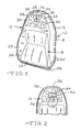
- a seat back having a halo opening and a trim cover closed around the opening by the closure of the present invention is shown in Figures 1 and 2 and designated generally at 10.
- the seat back 10 includes a frame 76, shown in Figure 3, covered by upholstery which includes a foam pad 78 and a trim cover 12 over the foam pad.
- the trim cover 12 includes a front trim cover 14 and a back trim cover 16 which are joined together by a side trim cover 18.
- the front, rear and side trim covers are joined together by a plurality of sewn seams 20 and may each be constructed of several pieces of a sheet material joined together by seams.
- the front trim cover 14 is formed in part by pieces 22 and 23 joined together by seam 24.
- the seat back 10 is of the so-called "halo" type which has a large hole 26 through the upper portion of the seat back.
- the hole 26 is generally rectangular in shape.
- the front trim cover 14, surrounding the hole 26, is made of four pieces 28 joined together by diagonal seams 30 which radiate from the corners of the hole 26.
- the front trim cover includes an opening formed by the edges 32 of the pieces 28. These edges 32 are attached to edges 34 of corresponding pieces 36 of the rear trim cover 16 shown in Figure 2 by the closure of the present invention.
- the trim cover 12 is constructed by sewing the front, rear and side trim covers together, forming an envelope having an open lower end 38.
- the trim cover envelope is then installed over the seat back frame and foam pad by inserting the frame and pad into the envelope, through the open end 38.
- the front and rear trim covers are attached to one another around the hole 26.
- the closure of the present invention is shown in Figure 3 and consists of a pair of attaching clips 40 and 42.
- the attaching clips 40 and 42 are elongated plastic extrusions which are attached to the edges 32 and 34 of the front and rear trim cover pieces 28 and 36 respectively.
- the attaching clip 40 has a flat joining portion 44 which is sewn to the trim cover edge 32 by a pair of seams 46.
- the clip 42 has a flat joining portion 48 which is sewn to the trim cover edge 36 by a pair of seams 50.
- the attaching clip 42 has a pair of spaced legs 52 and 54 which form a receiving pocket 56 having an open end 58.
- the flat portion 48 of the clip 42 forms the distal end of the leg 52 which extends beyond the open end 58 of the receiving pocket.
- the legs 52 and 54 have inwardly directed flanges 60 having ramped surfaces 62 and forming shoulders 64 facing the interior of the receiving pocket 56.
- the attaching clip 40 includes an arrow shaped barb 66 along one edge of the flat portion 44 which is sized so as to fit within the receiving pocket 56 by deflection of the legs 52 and 54 away from one another.
- the barb 66 has shoulders 68 which catch on the shoulders 64 of the flanges 60 to retain the barb within the receiving pocket.
- the trim cover 28 extends from the attaching clip 40 to the right as shown in Figure 3 and overlies the trim cover 36 which also extends to the right from attaching clip 42. The result is a finished appearance of the trim cover 28 overlying the trim cover 36. There is no exposed attaching hardware, thus resulting in a soft trim-to-trim appearance in the seat back hole 26.
- the attaching clip 42 has an extension 70 from the closed end 72 of the receiving pocket which has a reverse bent end 74 forming a hook 75 for mounting the attaching clip 42 to the frame 76 or other structure in the seat back 10.
- the closure may be constructed with two clips that fasten to one another without being attached to the frame or a supporting structure of the seat back.
- the attaching clip 42 would not have the extension 70 forming the hook 75.
- the trim cover around the hole 26 in seat back 10 is closed by four pairs of attaching clips 40 and 42.
- the four edges 32 of the trim cover pieces 28 will each have a clip 42 sewn thereto.
- the edges 34 of trim cover pieces 36 will each have a clip 40 sewn thereto.
- the clips are elongated plastic extrusions and extend along most of the length of edges 32 and 34. To facilitate assembly, the clips are shorter than the edges and do not extend completely to the corners of the hole 26 formed by seams 30.
- the closure of the present invention provides an easily assembled closure of the front and rear trim covers around a halo opening in a seat back.
- the closure results in a trim-to-trim finish without the rigid ring shown in the prior art.
- the trim cover is closed around the halo opening after assembly of the cover over the seat back. This allows the cover to be assembled around its periphery into an envelope before it is installed on the seat back. This avoids the need for difficult and time consuming sewing of the trim cover after being wrapped around the seat back frame and cushion.
- the closure of the present invention has its greatest utility around a seat back halo opening, the closure can also be used in other locations where the seat cover must be closed after assembly and a trim-to-trim appearance is desired.
Landscapes
- Engineering & Computer Science (AREA)
- Aviation & Aerospace Engineering (AREA)
- Transportation (AREA)
- Mechanical Engineering (AREA)
- Seats For Vehicles (AREA)
Abstract
Description
- The present invention relates to a closure for a seat trim cover and in particular to a closure especially suited for closing a seat trim cover around a halo opening in a seat back. In trimming automotive seat assemblies with soft trim, a neat appearance and ease of manufacture are extremely important. Today's motor vehicle purchasers demand interior trim having clean and neat lines with raw material edges hidden from view. In order to reduce seat manufacturing cost, it is desirable to employ processes which employ low cycle times and which can be carried out with a high degree of accuracy.
- The trimming of motor vehicle seat assemblies becomes particularly difficult when the seat is of the so-called "halo" type which has a large hole through the upper portion of the seat back. The front and rear sections of the trim cover must be connected around the peripheral edge of the seat back and further they must be joined within the hole through the seat back. One approach toward connecting the cover sections in the hole area is to sew them together in that region. This approach however, requires the front or rear trim cover to be fed through the hole and then spread out over the respective seat back portion before the front and rear trim covers are connected together around the periphery of the seat back. This operation is highly labor intensive and accordingly imposes cost penalties.
- Another approach toward connecting the trim covers in the hole area is the use of a ridged ring member that is installed within the seat back hole. The ring member includes a flange portion which engages the trim cover on one side of the seat back and has another flange with a reversely bent edge channel. A brake-over strip affixed to the other trim covers fits within the channel formed by the bent flange and is retained therein to complete the trimming of a seat back hole. However, in some instances, the use of a rigid ring member in a halo opening is undesirable and a softer appearance, such as that formed with a trim-to-trim attachment, is preferred.
- Accordingly, it is an objective of the present invention to provide a closure for joining the front and rear trim covers together in the hole of a halo seat back after the trim cover has been applied to the seat back. This eliminates the labor intensive and costly process of sewing the front and rear trim covers together around the periphery of the seat back after the cover has been installed on the seat back.
- With the closure of the present invention, the front and rear trim covers are sewn together about their peripheries, forming an envelope having an open end for insertion of the seat back into the envelope. The front and rear trim covers have openings for alignment with the hole in the seat back. Fastening clips are attached to the front and rear trim covers around the edges of the trim cover openings. The clips couple to one another to attach the front trim cover to the rear trim cover around the hole in the seat back. The attaching clip fastened to one trim cover has a projecting barb while the clip fastened to the other trim cover has a pocket for receiving the projecting barb. The pocket includes inwardly extending flanges which engage the barb and prevent its removal from the receiving pocket. Additionally, the attaching clip forming the pocket may also include a mounting hook to attach the clip to a supporting structure within the seat back, such as a seat back frame or a support wire mounted to the frame.
- Further objects, features and advantages of the invention will become apparent from a consideration of the following description and the appended claims when taken in connection with the accompanying drawings.
-
- Figure 1 is a front view of the seat back having the closure of the present invention;
- Figure 2 is a rear view of the seat back shown in Figure 1; and
- Figure 3 is a sectional view showing the trim covers closed around the halo opening with the closure of the present invention as seen from substantially the line 3-3 of Figure 2.
- A seat back having a halo opening and a trim cover closed around the opening by the closure of the present invention is shown in Figures 1 and 2 and designated generally at 10. The
seat back 10 includes aframe 76, shown in Figure 3, covered by upholstery which includes afoam pad 78 and atrim cover 12 over the foam pad. Thetrim cover 12 includes afront trim cover 14 and aback trim cover 16 which are joined together by aside trim cover 18. The front, rear and side trim covers are joined together by a plurality ofsewn seams 20 and may each be constructed of several pieces of a sheet material joined together by seams. For example, thefront trim cover 14 is formed in part bypieces seam 24. - The
seat back 10 is of the so-called "halo" type which has a large hole 26 through the upper portion of the seat back. In the seat back shown in Figure 1, the hole 26 is generally rectangular in shape. Thefront trim cover 14, surrounding the hole 26, is made of fourpieces 28 joined together bydiagonal seams 30 which radiate from the corners of the hole 26. The front trim cover includes an opening formed by theedges 32 of thepieces 28. Theseedges 32 are attached toedges 34 ofcorresponding pieces 36 of therear trim cover 16 shown in Figure 2 by the closure of the present invention. - The
trim cover 12 is constructed by sewing the front, rear and side trim covers together, forming an envelope having an openlower end 38. The trim cover envelope is then installed over the seat back frame and foam pad by inserting the frame and pad into the envelope, through theopen end 38. Once the frame is covered by thetrim cover 12, the front and rear trim covers are attached to one another around the hole 26. - The closure of the present invention is shown in Figure 3 and consists of a pair of attaching
clips 40 and 42. The attachingclips 40 and 42 are elongated plastic extrusions which are attached to theedges trim cover pieces trim cover edge 32 by a pair of seams 46. Likewise, theclip 42 has a flat joiningportion 48 which is sewn to thetrim cover edge 36 by a pair of seams 50. - The attaching
clip 42 has a pair ofspaced legs 52 and 54 which form a receivingpocket 56 having an open end 58. Theflat portion 48 of theclip 42 forms the distal end of theleg 52 which extends beyond the open end 58 of the receiving pocket. At the open end 58, thelegs 52 and 54 have inwardly directed flanges 60 having rampedsurfaces 62 and formingshoulders 64 facing the interior of the receivingpocket 56. - The attaching clip 40 includes an arrow shaped
barb 66 along one edge of the flat portion 44 which is sized so as to fit within the receivingpocket 56 by deflection of thelegs 52 and 54 away from one another. Thebarb 66 hasshoulders 68 which catch on theshoulders 64 of the flanges 60 to retain the barb within the receiving pocket. - The
trim cover 28 extends from the attaching clip 40 to the right as shown in Figure 3 and overlies thetrim cover 36 which also extends to the right from attachingclip 42. The result is a finished appearance of thetrim cover 28 overlying thetrim cover 36. There is no exposed attaching hardware, thus resulting in a soft trim-to-trim appearance in the seat back hole 26. - The attaching
clip 42 has anextension 70 from the closed end 72 of the receiving pocket which has areverse bent end 74 forming ahook 75 for mounting the attachingclip 42 to theframe 76 or other structure in the seat back 10. Once theclip 42 is installed on the frame, compression of thefoam pad 78 by the trim cover causes the attachingclip 42 to be urged to the right in Figure 3, seating thehook 75 onto theframe 76. - It may be possible to construct the closure with two clips that fasten to one another without being attached to the frame or a supporting structure of the seat back. In such a case, the attaching
clip 42 would not have theextension 70 forming thehook 75. - The trim cover around the hole 26 in
seat back 10 is closed by four pairs of attachingclips 40 and 42. The fouredges 32 of thetrim cover pieces 28 will each have aclip 42 sewn thereto. Theedges 34 oftrim cover pieces 36 will each have a clip 40 sewn thereto. The clips are elongated plastic extrusions and extend along most of the length ofedges seams 30. - The closure of the present invention provides an easily assembled closure of the front and rear trim covers around a halo opening in a seat back. The closure results in a trim-to-trim finish without the rigid ring shown in the prior art. In addition, the trim cover is closed around the halo opening after assembly of the cover over the seat back. This allows the cover to be assembled around its periphery into an envelope before it is installed on the seat back. This avoids the need for difficult and time consuming sewing of the trim cover after being wrapped around the seat back frame and cushion. While the closure of the present invention has its greatest utility around a seat back halo opening, the closure can also be used in other locations where the seat cover must be closed after assembly and a trim-to-trim appearance is desired.
- It is to be understood that the invention is not limited to the exact construction illustrated and described above, but that various changes and modifications may be made without departing from the spirit and scope of the invention as defined in the following claims.
Claims (14)
Applications Claiming Priority (2)
| Application Number | Priority Date | Filing Date | Title |
|---|---|---|---|
| US194216 | 1994-02-09 | ||
| US08/194,216 US5401075A (en) | 1994-02-09 | 1994-02-09 | Closure for a seat trim cover |
Publications (3)
| Publication Number | Publication Date |
|---|---|
| EP0667257A2 true EP0667257A2 (en) | 1995-08-16 |
| EP0667257A3 EP0667257A3 (en) | 1996-02-28 |
| EP0667257B1 EP0667257B1 (en) | 1998-07-08 |
Family
ID=22716755
Family Applications (1)
| Application Number | Title | Priority Date | Filing Date |
|---|---|---|---|
| EP95100748A Expired - Lifetime EP0667257B1 (en) | 1994-02-09 | 1995-01-20 | Closure for a seat trim cover |
Country Status (3)
| Country | Link |
|---|---|
| US (1) | US5401075A (en) |
| EP (1) | EP0667257B1 (en) |
| DE (1) | DE69503270T2 (en) |
Cited By (1)
| Publication number | Priority date | Publication date | Assignee | Title |
|---|---|---|---|---|
| CN108372817A (en) * | 2016-10-13 | 2018-08-07 | 李尔公司 | Seat-assembly with bolster sub-component |
Families Citing this family (32)
| Publication number | Priority date | Publication date | Assignee | Title |
|---|---|---|---|---|
| US5586807A (en) * | 1995-02-10 | 1996-12-24 | Atoma International Of America, Inc. | Vehicle seat trim cover retainer |
| US5658046A (en) * | 1996-01-16 | 1997-08-19 | Lear Corporation | Vehicle seat trim cover attachment strip |
| WO1998017139A1 (en) * | 1996-10-24 | 1998-04-30 | Mattel, Inc. | Soft goods fastener |
| US5733001A (en) * | 1996-11-19 | 1998-03-31 | Roberts; Clifford D. | Seat cover retainer apparatus and method of using same |
| US5971478A (en) * | 1997-08-13 | 1999-10-26 | Lear Corporation | J-strip with hook-and-loop attachment for trim cover |
| US5826939A (en) * | 1997-08-13 | 1998-10-27 | Lear Corporation | Method and apparatus for attaching a trim cover to a seat frame |
| US6220661B1 (en) | 1999-04-19 | 2001-04-24 | Steelcase Development Inc. | Chair back and method of assembly |
| US6406093B1 (en) | 2000-03-29 | 2002-06-18 | Lear Corporation | Attachment for seat assembly |
| US6857699B2 (en) * | 2002-08-22 | 2005-02-22 | Eagle Ottawa, Llc | Head restraint assembly and method for its manufacturing |
| JP4086616B2 (en) * | 2002-10-16 | 2008-05-14 | 株式会社デルタツーリング | Sheet structure |
| US7021718B2 (en) | 2002-12-02 | 2006-04-04 | Dahti, Inc. | Method and apparatus for attaching accessories to load-bearing fabric |
| US20050194829A1 (en) * | 2004-03-08 | 2005-09-08 | Chad Aerts | Fabric attachment device |
| US7195277B2 (en) * | 2004-12-01 | 2007-03-27 | Lear Corporation | Vehicle seat assembly |
| DE102005028569B4 (en) * | 2005-06-21 | 2008-11-13 | Johnson Controls Gmbh | Profile and arrangement for fixing a cover to a support body, in particular a headrest of a motor vehicle and a headrest equipped therewith |
| US7487575B2 (en) * | 2005-07-13 | 2009-02-10 | Lyle J Smith | System for attaching trim covers to a flexible substrate |
| US7585025B2 (en) * | 2006-12-10 | 2009-09-08 | Lear Corporation | Ergonomic closeout |
| US8091184B2 (en) * | 2007-04-19 | 2012-01-10 | Hope Global, Division Of Nfa Corp. | Festooned trim clip system and method for attaching festooned clips to a substrate |
| US8099837B2 (en) * | 2007-09-07 | 2012-01-24 | Hope Global, Division Of Nfa Corporation | Low-profile upholstery clip for attaching a bead to a foam substrate |
| DE102007059454B4 (en) * | 2007-12-10 | 2012-01-19 | himolla Polstermöbel GmbH | Device for joining furniture covers |
| JP5644688B2 (en) * | 2011-06-14 | 2014-12-24 | トヨタ紡織株式会社 | Vehicle seat |
| JP5876255B2 (en) * | 2011-09-08 | 2016-03-02 | 株式会社イレブンインターナショナル | Seat cover and cover fitting |
| JP5831745B2 (en) * | 2011-09-17 | 2015-12-09 | スズキ株式会社 | Seat skin mounting structure |
| JP5922234B2 (en) * | 2012-06-29 | 2016-05-24 | 株式会社タチエス | Vehicle seat |
| US9661930B2 (en) | 2012-09-21 | 2017-05-30 | Steelcase Inc. | Chair construction |
| US9027994B2 (en) * | 2012-12-31 | 2015-05-12 | Ts Tech Co., Ltd. | Locking structure for skin terminals of vehicle seat and vehicle seat provided with locking structure |
| WO2014129087A1 (en) * | 2013-02-22 | 2014-08-28 | 株式会社タチエス | Trim cover affixation structure for vehicle seat, and vehicle seat |
| JP6355201B2 (en) * | 2014-11-18 | 2018-07-11 | 株式会社タチエス | Skin fixing structure and armrest |
| US9706846B2 (en) | 2015-06-09 | 2017-07-18 | Exemplis Corporation | Chair back assembly |
| US9834431B2 (en) | 2015-08-28 | 2017-12-05 | Hope Global, Division Of Nfa Corp. | Listing bead for upholstery clips |
| DE102016205472A1 (en) * | 2016-04-01 | 2017-10-05 | Ford Global Technologies, Llc | Upholstery element for a vehicle seat |
| US10604040B2 (en) * | 2017-05-24 | 2020-03-31 | Lear Corporation | Seat for a vehicle |
| US10473136B2 (en) * | 2017-05-25 | 2019-11-12 | Ford Global Technologies, Llc | Vehicle seating cushion with snap-fit fasteners to interconnect with snap-fit receivers on a structural support |
Citations (5)
| Publication number | Priority date | Publication date | Assignee | Title |
|---|---|---|---|---|
| DE2826356A1 (en) * | 1978-06-16 | 1980-01-03 | Daimler Benz Ag | Flexible covering material for vehicle seat headrest - has fastener which consists of elastic grooved section with catch fitted |
| US4723816A (en) * | 1986-09-22 | 1988-02-09 | Johnson Service Company | Snap-on clip mounting system for load bearing fabric seat members |
| US4786103A (en) * | 1988-03-21 | 1988-11-22 | Hoover Universal, Inc. | Vehicle seat trim assembly |
| US5187843A (en) * | 1991-01-17 | 1993-02-23 | Lynch James P | Releasable fastener assembly |
| FR2686553A1 (en) * | 1992-01-24 | 1993-07-30 | Faure Bertrand Automobile | Improvements to the devices for fastening the edges of seat cushion covers to the frameworks of these cushions |
Family Cites Families (2)
| Publication number | Priority date | Publication date | Assignee | Title |
|---|---|---|---|---|
| US2100557A (en) * | 1933-07-27 | 1937-11-30 | Hookless Fastener Co | Separable fastener |
| JPH07100041B2 (en) * | 1989-02-20 | 1995-11-01 | ワイケイケイ株式会社 | Manufacturing method of slide fastener with decorative teeth |
-
1994
- 1994-02-09 US US08/194,216 patent/US5401075A/en not_active Expired - Fee Related
-
1995
- 1995-01-20 EP EP95100748A patent/EP0667257B1/en not_active Expired - Lifetime
- 1995-01-20 DE DE69503270T patent/DE69503270T2/en not_active Expired - Fee Related
Patent Citations (5)
| Publication number | Priority date | Publication date | Assignee | Title |
|---|---|---|---|---|
| DE2826356A1 (en) * | 1978-06-16 | 1980-01-03 | Daimler Benz Ag | Flexible covering material for vehicle seat headrest - has fastener which consists of elastic grooved section with catch fitted |
| US4723816A (en) * | 1986-09-22 | 1988-02-09 | Johnson Service Company | Snap-on clip mounting system for load bearing fabric seat members |
| US4786103A (en) * | 1988-03-21 | 1988-11-22 | Hoover Universal, Inc. | Vehicle seat trim assembly |
| US5187843A (en) * | 1991-01-17 | 1993-02-23 | Lynch James P | Releasable fastener assembly |
| FR2686553A1 (en) * | 1992-01-24 | 1993-07-30 | Faure Bertrand Automobile | Improvements to the devices for fastening the edges of seat cushion covers to the frameworks of these cushions |
Cited By (2)
| Publication number | Priority date | Publication date | Assignee | Title |
|---|---|---|---|---|
| CN108372817A (en) * | 2016-10-13 | 2018-08-07 | 李尔公司 | Seat-assembly with bolster sub-component |
| CN108372817B (en) * | 2016-10-13 | 2021-01-15 | 李尔公司 | Seat assembly with pillow subassembly |
Also Published As
| Publication number | Publication date |
|---|---|
| DE69503270T2 (en) | 1999-03-04 |
| DE69503270D1 (en) | 1998-08-13 |
| US5401075A (en) | 1995-03-28 |
| EP0667257A3 (en) | 1996-02-28 |
| EP0667257B1 (en) | 1998-07-08 |
Similar Documents
| Publication | Publication Date | Title |
|---|---|---|
| EP0667257B1 (en) | Closure for a seat trim cover | |
| US7222915B2 (en) | Backrest of an automobile vehicle seat | |
| JPH032222Y2 (en) | ||
| US5658046A (en) | Vehicle seat trim cover attachment strip | |
| US4865383A (en) | Fastening assembly for vehicle seat upholstery | |
| US5529373A (en) | Apparatus and method for covering a chair form with fabric | |
| US5326151A (en) | Seat cover member with cable tie closure | |
| US5879051A (en) | Device and method for fixing a seat covering and the seat obtained | |
| EP1996443A2 (en) | Stroller soft goods attachment | |
| US4872724A (en) | Fixing device for a covering, especially a covering of a seat | |
| KR970701513A (en) | Car Seat Cover Cover Retainer | |
| US4786103A (en) | Vehicle seat trim assembly | |
| US5168615A (en) | Method of assembling a foam cushion | |
| US4352524A (en) | Improvement in upholstered furniture | |
| US4637650A (en) | Top cover member fixing arrangement in a vehicle seat | |
| CN114096436A (en) | Chair | |
| JP4731753B2 (en) | Upholstery mounting structure for chairs | |
| US2876971A (en) | Means for securing ceiling panels in automobiles | |
| JPH11342278A (en) | Structure of sheet terminal treatment | |
| JPH06304353A (en) | Drawing part structure of skin material of sheet for vehicle | |
| JPH08323073A (en) | Seat back of seat for automobile | |
| JPH0575025U (en) | Belt hole structure of seat belt in seat cushion | |
| JPS6322931Y2 (en) | ||
| JPH0226363Y2 (en) | ||
| GB2318508A (en) | Attaching covers to seats |
Legal Events
| Date | Code | Title | Description |
|---|---|---|---|
| PUAI | Public reference made under article 153(3) epc to a published international application that has entered the european phase |
Free format text: ORIGINAL CODE: 0009012 |
|
| AK | Designated contracting states |
Kind code of ref document: A2 Designated state(s): DE ES FR GB IT |
|
| PUAL | Search report despatched |
Free format text: ORIGINAL CODE: 0009013 |
|
| AK | Designated contracting states |
Kind code of ref document: A3 Designated state(s): DE ES FR GB IT |
|
| 17P | Request for examination filed |
Effective date: 19960827 |
|
| 17Q | First examination report despatched |
Effective date: 19961202 |
|
| GRAG | Despatch of communication of intention to grant |
Free format text: ORIGINAL CODE: EPIDOS AGRA |
|
| GRAG | Despatch of communication of intention to grant |
Free format text: ORIGINAL CODE: EPIDOS AGRA |
|
| GRAH | Despatch of communication of intention to grant a patent |
Free format text: ORIGINAL CODE: EPIDOS IGRA |
|
| GRAH | Despatch of communication of intention to grant a patent |
Free format text: ORIGINAL CODE: EPIDOS IGRA |
|
| GRAA | (expected) grant |
Free format text: ORIGINAL CODE: 0009210 |
|
| AK | Designated contracting states |
Kind code of ref document: B1 Designated state(s): DE ES FR GB IT |
|
| PG25 | Lapsed in a contracting state [announced via postgrant information from national office to epo] |
Ref country code: IT Free format text: LAPSE BECAUSE OF FAILURE TO SUBMIT A TRANSLATION OF THE DESCRIPTION OR TO PAY THE FEE WITHIN THE PRESCRIBED TIME-LIMIT;WARNING: LAPSES OF ITALIAN PATENTS WITH EFFECTIVE DATE BEFORE 2007 MAY HAVE OCCURRED AT ANY TIME BEFORE 2007. THE CORRECT EFFECTIVE DATE MAY BE DIFFERENT FROM THE ONE RECORDED. Effective date: 19980708 Ref country code: ES Free format text: THE PATENT HAS BEEN ANNULLED BY A DECISION OF A NATIONAL AUTHORITY Effective date: 19980708 |
|
| REF | Corresponds to: |
Ref document number: 69503270 Country of ref document: DE Date of ref document: 19980813 |
|
| ET | Fr: translation filed | ||
| PLBE | No opposition filed within time limit |
Free format text: ORIGINAL CODE: 0009261 |
|
| STAA | Information on the status of an ep patent application or granted ep patent |
Free format text: STATUS: NO OPPOSITION FILED WITHIN TIME LIMIT |
|
| 26N | No opposition filed | ||
| REG | Reference to a national code |
Ref country code: GB Ref legal event code: IF02 |
|
| PGFP | Annual fee paid to national office [announced via postgrant information from national office to epo] |
Ref country code: FR Payment date: 20051208 Year of fee payment: 12 |
|
| PGFP | Annual fee paid to national office [announced via postgrant information from national office to epo] |
Ref country code: GB Payment date: 20051213 Year of fee payment: 12 |
|
| PGFP | Annual fee paid to national office [announced via postgrant information from national office to epo] |
Ref country code: DE Payment date: 20060131 Year of fee payment: 12 |
|
| PG25 | Lapsed in a contracting state [announced via postgrant information from national office to epo] |
Ref country code: DE Free format text: LAPSE BECAUSE OF NON-PAYMENT OF DUE FEES Effective date: 20070801 |
|
| GBPC | Gb: european patent ceased through non-payment of renewal fee |
Effective date: 20070120 |
|
| REG | Reference to a national code |
Ref country code: FR Ref legal event code: ST Effective date: 20070930 |
|
| PG25 | Lapsed in a contracting state [announced via postgrant information from national office to epo] |
Ref country code: GB Free format text: LAPSE BECAUSE OF NON-PAYMENT OF DUE FEES Effective date: 20070120 |
|
| PG25 | Lapsed in a contracting state [announced via postgrant information from national office to epo] |
Ref country code: FR Free format text: LAPSE BECAUSE OF NON-PAYMENT OF DUE FEES Effective date: 20070131 |