EP0667173B1 - Destruction of contaminants using a low-energy electron beam - Google Patents
Destruction of contaminants using a low-energy electron beam Download PDFInfo
- Publication number
- EP0667173B1 EP0667173B1 EP95101750A EP95101750A EP0667173B1 EP 0667173 B1 EP0667173 B1 EP 0667173B1 EP 95101750 A EP95101750 A EP 95101750A EP 95101750 A EP95101750 A EP 95101750A EP 0667173 B1 EP0667173 B1 EP 0667173B1
- Authority
- EP
- European Patent Office
- Prior art keywords
- electrons
- fluid
- electron
- electron beam
- thousand
- Prior art date
- Legal status (The legal status is an assumption and is not a legal conclusion. Google has not performed a legal analysis and makes no representation as to the accuracy of the status listed.)
- Expired - Lifetime
Links
Images

Classifications
-
- C—CHEMISTRY; METALLURGY
- C02—TREATMENT OF WATER, WASTE WATER, SEWAGE, OR SLUDGE
- C02F—TREATMENT OF WATER, WASTE WATER, SEWAGE, OR SLUDGE
- C02F1/00—Treatment of water, waste water, or sewage
- C02F1/30—Treatment of water, waste water, or sewage by irradiation
-
- B—PERFORMING OPERATIONS; TRANSPORTING
- B01—PHYSICAL OR CHEMICAL PROCESSES OR APPARATUS IN GENERAL
- B01D—SEPARATION
- B01D53/00—Separation of gases or vapours; Recovering vapours of volatile solvents from gases; Chemical or biological purification of waste gases, e.g. engine exhaust gases, smoke, fumes, flue gases, aerosols
- B01D53/007—Separation of gases or vapours; Recovering vapours of volatile solvents from gases; Chemical or biological purification of waste gases, e.g. engine exhaust gases, smoke, fumes, flue gases, aerosols by irradiation
-
- B—PERFORMING OPERATIONS; TRANSPORTING
- B01—PHYSICAL OR CHEMICAL PROCESSES OR APPARATUS IN GENERAL
- B01D—SEPARATION
- B01D53/00—Separation of gases or vapours; Recovering vapours of volatile solvents from gases; Chemical or biological purification of waste gases, e.g. engine exhaust gases, smoke, fumes, flue gases, aerosols
- B01D53/32—Separation of gases or vapours; Recovering vapours of volatile solvents from gases; Chemical or biological purification of waste gases, e.g. engine exhaust gases, smoke, fumes, flue gases, aerosols by electrical effects other than those provided for in group B01D61/00
-
- B—PERFORMING OPERATIONS; TRANSPORTING
- B01—PHYSICAL OR CHEMICAL PROCESSES OR APPARATUS IN GENERAL
- B01J—CHEMICAL OR PHYSICAL PROCESSES, e.g. CATALYSIS OR COLLOID CHEMISTRY; THEIR RELEVANT APPARATUS
- B01J19/00—Chemical, physical or physico-chemical processes in general; Their relevant apparatus
- B01J19/08—Processes employing the direct application of electric or wave energy, or particle radiation; Apparatus therefor
- B01J19/081—Processes employing the direct application of electric or wave energy, or particle radiation; Apparatus therefor employing particle radiation or gamma-radiation
- B01J19/085—Electron beams only
-
- C—CHEMISTRY; METALLURGY
- C02—TREATMENT OF WATER, WASTE WATER, SEWAGE, OR SLUDGE
- C02F—TREATMENT OF WATER, WASTE WATER, SEWAGE, OR SLUDGE
- C02F1/00—Treatment of water, waste water, or sewage
- C02F1/30—Treatment of water, waste water, or sewage by irradiation
- C02F1/305—Treatment of water, waste water, or sewage by irradiation with electrons
-
- B—PERFORMING OPERATIONS; TRANSPORTING
- B01—PHYSICAL OR CHEMICAL PROCESSES OR APPARATUS IN GENERAL
- B01D—SEPARATION
- B01D2257/00—Components to be removed
- B01D2257/20—Halogens or halogen compounds
- B01D2257/206—Organic halogen compounds
-
- B—PERFORMING OPERATIONS; TRANSPORTING
- B01—PHYSICAL OR CHEMICAL PROCESSES OR APPARATUS IN GENERAL
- B01D—SEPARATION
- B01D2257/00—Components to be removed
- B01D2257/20—Halogens or halogen compounds
- B01D2257/206—Organic halogen compounds
- B01D2257/2064—Chlorine
-
- B—PERFORMING OPERATIONS; TRANSPORTING
- B01—PHYSICAL OR CHEMICAL PROCESSES OR APPARATUS IN GENERAL
- B01D—SEPARATION
- B01D2259/00—Type of treatment
- B01D2259/80—Employing electric, magnetic, electromagnetic or wave energy, or particle radiation
- B01D2259/812—Electrons
Definitions
- the invention relates to a method for reducing contaminants in a fluid, including the steps of:
- the invention further relates to an apparatus for reducing contaminants in a fluid, comprising:
- a method and an apparatus of the afore-mentioned kind is known from FR-A-2 575 938.
- a fluid in the sense of the present invention may be a gas or a liquid.
- the present inventors have observed that the use of such high-energy electron beams has the significant drawback that extensive shielding of any decontamination apparatus is required.
- the high-energy electron beam is injurious to life, as are the Bremsstrahlung and X-radiation that may be produced in such an apparatus. Consequently, such an apparatus must be large and bulky, because extensive shielding is required.
- the shielding also adds significantly to the cost of the apparatus, and limits its use in some situations of interest.
- FR-A-2 575 938 discloses a method and an apparatus for reducing contaminants in fluids by irradiating the fluid with electrons which are generated with primary electron energies of from about 100 to 200 thousand volts and pass through a window which is configured such that the electrons of the beam have secondary energies of the same range when entering the fluid.
- GB-A-2 173 799 discloses an apparatus for the desulphurization and denitration of exhaust gases by electron irradiation of the exhaust gases to which ammonia has been added before irradiation, the apparatus consisting essentially of an exhaust gas channel and at least one low energy electron beam source with an electron beam potential in the region of 150-300 thousand volts, i.e. the electrons of the beam are accelerated to a primary electron energy of 150-300 thousand electron volts.
- DE 36 25 232 A1 discloses a method and an apparatus for the reduction of noxious carbon hydrides in liquids by irradiation with electrons which have been accelerated by voltages between 150 and 350 thousand volts, preferably 250 and 300 thousand volts.
- this object is achieved in that the electrons of the beam have an average injected energy of from 45 thousand to 55 thousand electron volts upon entering the fluid.
- this object is achieved in that the material and the thicknes of the window is selected such that the electrons of the beam have an average injected energy of from 45 thousand to 55 thousand electron volts upon entering the fluid.
- the present invention provides a method and apparatus for reducing the contaminant levels in gases and liquids.
- the approach of the invention is operable to destroy various types of organic and inorganic contaminants.
- the apparatus is relatively compact, is relatively inexpensive, and does not require an excessive energy use. Further, it requires only minimal shielding for the safety of users.
- a method for reducing contaminants in a fluid comprises the steps of providing a fluid containing a contaminant compound, and producing a beam of electrons.
- the method further includes directing the beam of electrons through the fluid, preferably after passing through a thin window from the electron beam source into the fluid, to reduce the concentration of the contaminant in the fluid.
- the electrons of the beam have an average injected energy of from 45 to 55 thousand electron volts (kev) upon entering the fluid after passing through the window.
- the energy distribution of the electrons transmitted through the window and entering the fluid is a poisson-like distribution which depends on the window material and its thickness, and the primary electron energy.
- the peak of the distribution is near 45-50 kev with a tail tending toward zero.
- a method for reducing contaminants in a fluid comprises the steps of providing an apparatus comprising an electron beam source of a beam of electrons with the electrons having a primary energy of from 90 to 110 thousand electron volts, a contaminant-reduction cell, and an electron-beam transmissive window between the electron beam source and the cell.
- the window is selected such that the average energy of the electrons is from 45 to 55 thousand electron volts after passing through the window, depending upon the material and thickness of the window.
- the method further includes producing an electron beam with the apparatus, introducing a fluid containing a contaminant compound into the cell, and passing the electron beam from the source, through the window, and through the cell containing the contaminant compound.
- the electron beam reduces the concentration of the contaminant compounds in the cell.
- the approach of the invention utilizes a low-energy electron beam that requires only limited shielding.
- the low-energy electron beam source and its associated cell are less expensive and more compact than a high-energy system.
- the apparatus is therefore more suitable for utilization near persons, in a mobile form, and otherwise.
- the present invention provides an advance in the art of contaminant/pollutant reduction in fluids such as air and water, for a variety of types of such contaminants.
- Figure 1 depicts the steps of a preferred approach to practicing the invention.
- a contaminated fluid such as air or water is provided, numeral 20.
- Organic contaminants of air that may be removed by destruction include, for example, VOCs (volatile organic compounds), benzene, trichloroethane, acetone, toluene, perchloroethylene, and other compounds.
- VOCs volatile organic compounds
- benzene trichloroethane
- acetone toluene
- perchloroethylene perchloroethylene
- organic is interpreted broadly herein to include a broad range of compounds containing hydrogen, carbon, and other elements.
- Organic specifically includes, but is not limited to, modified hydrocarbons having simple and complex substituents such as, for example, chlorine.
- the concentrations of the contaminants are typically at least about 100 parts per million of the air.
- the electron beam contains electrons having a primary energy (that is, the energy when produced) of from 90 thousand electron volts ("keV") to 110 thousand electron volts.
- keV electron volts
- Such a beam is typically produced by generating free electrons and accelerating the electrons through a potential of the indicated voltage.
- the electron energy bounds are defined on the lower end by the energy needed to traverse the vacuum interface foil (to be discussed subsequently in relation to Figure 2) and on the higher end by the techniques and equipment used to produce the electron beam and by the required shielding. On the lower end, approximately one-half of the electrons with about one-half of their original energy pass through the foil, resulting in an average injected energy of from 45 to 55 kev.
- the percentage of the beam lost in the foil increases dramatically as the energy is lowered.
- a minimum primary beam of energy of 90 keV is required for satisfactory commercial operation, although positive results can be obtained with somewhat lower energy.
- the average injected energy should not be less than 45 kev for satisfactory commercial results, as less energetic beams generally cannot achieve sufficient contaminant reduction.
- the electron beam can be either pulsed or continuous wave (CW). Generally, the beam is pulsed for reasons of practicality.
- the electron gun operates at a relatively low pressure, as for example about 2Pa (15 mTorr), and must be separated from the outside atmospheric pressure by a solid barrier or foil window.
- the electron gun may operate at elevated temperatures and at high vacuums, as well.
- the electrons must pass through the foil window as they leave the electron gun. As the electrons traverse the foil window, they lose some of their energy, which is dissipated as heat in the foil. This energy must be conducted away by either the support structure or the fluid medium outside the foil.
- the pulse width is set so that the rate of energy deposition in the foil window is lower than that required to cause window failure from excessive heating. Improved windows, window support cooling, or increased fluid medium cooling can increase the pulse length capabilities, which in turn would increase the allowed flow rate of contaminated fluid through the system.
- the electron beam is pulsed from a fully off-state to a fully on-state in a succession of pulses.
- each pulse it is preferred that each pulse last from 5 to 50 microseconds.
- the pulse duration and repetition rate are determined by the particular foil material, the foil support structure, and any cooling which may be present.
- the electron beam is directed through the fluid, numeral 24.
- the electron beam is usually produced in a vacuum or a plasma, and is passed through a window to the fluid.
- FIG. 2 illustrates an apparatus 30 operable to accomplish the method of the invention.
- the apparatus includes an electron beam source 32 that produces an electron beam with electrons having energy in the range of from 90 keV to 110 keV.
- Such electron beam sources 32 are well known in the art for use in other applications. A description of such a source is found in S. Liao, "Microwave Electron Tube Devices", Prentice-Hall, 1988, page 42, which description is incorporated herein by reference.
- the cost of such a low-energy electron beam source is less than 10 percent of the cost of a high-energy electron beam source in the 0.3 to 8.0 million electron volt (MeV) range of comparable beam current.
- the electron beam is produced in a partial vacuum, and the beam passes out of the source 32 through an electron-transmissive window 34.
- An operable window 34 is a piece of titanium foil about 13 micrometers thick.
- the cell 36 comprises a chamber with a fluid inlet 38 and a fluid outlet 40. Contaminated fluid flows into the cell through the inlet 38, and decontaminated fluid flows out of the cell through the outlet 40.
- the cell 36 may be operated either in a continuous flow fashion or a batch fashion. In the latter case, only a single inlet/outlet would be required.
- the electron beam reacts with the contaminants in the fluid, causing their destruction and a resulting reduction in the contaminant level of the fluid.
- the operability of the invention has been demonstrated, and its operability does not depend upon any particular mode of reaction. However, by way of a possible explanation it is believed that the energetic electrons of the electron beam break the chemical bonds of the contaminants, which have chemical binding energies of less than 10 electron volts. The bonds of the resulting fragments are further broken, until eventually the resulting fragments are no longer injurious.
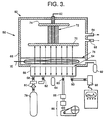
- the apparatus 50 includes an electron beam source 52, a window 54, a contaminant-reduction cell 56, an inlet 58 to the cell 56, an outlet 60 from the cell 56, about 32mm (1/8") of lead shielding or its equivalent (not shown in Figure 3) around the electron beam source, window, and cell, a power lead 62 to the electron beam source 52, and a vacuum line 64 to the electron beam source 52.
- the accelerated electrons pass through the window 54, which is preferably a titanium sheet about 13 micrometers thick, and enter the cell 56.
- the electrons interact with the contaminated fluid admitted through the inlet 58. Decontaminated fluid is removed from the outlet 60.
- the apparatus 50 of Figure 3 was used to determine the operability of the invention.
- the electron beam source was operated at a primary voltage of about 100 keV in pulses of 1 ampere current through the window and 25 microsecond pulse duration.
- the average energy of the injected electron beam energy after passing through the foil was about 45 keV.
- contaminated air with an initial contaminant concentration of 118 parts per million was introduced into the cell 56. This concentration is representative of the concentration found in the stack gases of fossil-fired power plants.
- the cell was operated in a batch fashion. That is, the cell was not operated in a continuous flowing mode, but with the contents sealed into the chamber so that the effect of the electron beam pulses could be assessed.
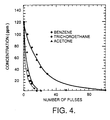
- the contaminants in the three experiments were, respectively, benzene, acetone, and 1,1,1 trichloroethane.
- the experiments were conducted by applying a number of electron beam pulses to the contaminated air in the cell, then discontinuing the electron irradiation so that the concentration of contaminant could be measured by the mass analyzer 92. After the contaminant content was measured, pulsed irradiation was resumed.
- Figure 4 shows the change in concentration of the contaminants as a function of the number of pulses.
- the contaminant contents are reduced below the limit of detection, about 5 ppm, in from 15 to 100 pulses, depending upon the contaminant.
- This result demonstrates the operability of the invention, and also suggests that a continuous flow process would be operable as long as the mean residence time of the contaminated gas within the apparatus permits each volume of gas to receive the required number of pulses.
Landscapes
- Chemical & Material Sciences (AREA)
- Engineering & Computer Science (AREA)
- Health & Medical Sciences (AREA)
- Toxicology (AREA)
- Chemical Kinetics & Catalysis (AREA)
- Organic Chemistry (AREA)
- Oil, Petroleum & Natural Gas (AREA)
- Analytical Chemistry (AREA)
- General Chemical & Material Sciences (AREA)
- Hydrology & Water Resources (AREA)
- General Health & Medical Sciences (AREA)
- Environmental & Geological Engineering (AREA)
- Water Supply & Treatment (AREA)
- Life Sciences & Earth Sciences (AREA)
- Plasma & Fusion (AREA)
- Physics & Mathematics (AREA)
- Physical Or Chemical Processes And Apparatus (AREA)
- Physical Water Treatments (AREA)
- Removal Of Specific Substances (AREA)
- Treating Waste Gases (AREA)
Description
- providing a fluid containing a contaminant compound;
- producing a beam of electrons; and
- directing the beam of electrons through the fluid to reduce the concentration of the contaminant compound in the fluid.
- an electron beam source of a beam of electrons with the electrons having an average primary engergy of from 90 thousand to 110 thousand electron volts;
- an electron-beam transmissive window through which the electron beam passes; and
- means for directing the beam of electrons through the fluid after passing through the window.
Claims (10)
- A method for reducing contaminants in a fluid, including the steps of:providing (20) a fluid containing a contaminant compound;producing (22) a beam of electrons; anddirecting (24) the beam of electrons through the fluid to reduce the concentration of the contaminant compound in the fluid,
characterized in that the electrons of the beam have an average injected energy of from 45 thousand to 55 thousand electron volts upon entering the fluid. - The method of claim 1, characterized in that the step of producing (22) a beam of electrons includes the step of producing a beam of electrons having an average energy of from 90 thousand to 110 thousand electron volts.
- The method of claim 1 or 2, characterized by the further steps of:passing the beam of electrons through an electron transmissive window (34; 54); anddirecting (24) the beam of electrons through the fluid after passing through the window (34; 54).
- The method of any of claims 1 - 3, characterized in that the step (20) of providing a fluid comprises the step of providing air containing a contaminant compound.
- The method of claim 4, characterized in that the contaminant compound is selected from the group consisting of a hydrocarbon, NOx, and SOx.
- The method of any of claims 1 - 5, characterized in that the step (20) of providing a fluid comprises the step of providing water containing a contaminant compound.
- The method of claim 6, characterized in that the contaminant compound is selected from the group consisting of polychlorinated biphenyl compounds, halogenated organic compounds, and mixtures thereof.
- The method of any of claims 1 - 7, characterized in that the step (22) of producing a beam of electrons comprises the step of pulsing an electron beam between an off-state and an on-state.
- The method of claim 8, characterized in that the electron beam is pulsed with a pulse duration of from 5 microseconds to 50 microseconds.
- An apparatus for reducing contaminants in a fluid, comprising:an electron beam source (32; 52) of a beam of electrons with the electrons having an average primary engergy of from 90 thousand to 110 thousand electron volts;an electron-beam transmissive window (34; 54) through which the electron beam passes; andmeans for directing (24) the beam of electrons through the fluid after passing through the window (34; 54),
characterized in that the material and the thickness of the window (34; 54) is selected such that the electrons of the beam have an average injected energy of from 45 thousand to 55 thousand electron volts upon entering the fluid.
Applications Claiming Priority (2)
| Application Number | Priority Date | Filing Date | Title |
|---|---|---|---|
| US08/195,663 US5561298A (en) | 1994-02-09 | 1994-02-09 | Destruction of contaminants using a low-energy electron beam |
| US195663 | 1994-02-09 |
Publications (2)
| Publication Number | Publication Date |
|---|---|
| EP0667173A1 EP0667173A1 (en) | 1995-08-16 |
| EP0667173B1 true EP0667173B1 (en) | 1999-01-13 |
Family
ID=22722256
Family Applications (1)
| Application Number | Title | Priority Date | Filing Date |
|---|---|---|---|
| EP95101750A Expired - Lifetime EP0667173B1 (en) | 1994-02-09 | 1995-02-09 | Destruction of contaminants using a low-energy electron beam |
Country Status (5)
| Country | Link |
|---|---|
| US (1) | US5561298A (en) |
| EP (1) | EP0667173B1 (en) |
| JP (1) | JPH07251026A (en) |
| KR (1) | KR950024797A (en) |
| DE (1) | DE69507169T2 (en) |
Families Citing this family (26)
| Publication number | Priority date | Publication date | Assignee | Title |
|---|---|---|---|---|
| DE19538604C1 (en) * | 1995-10-09 | 1997-05-22 | Spezial Erden Produktion Rosem | Process for the degradation of stable organic pollutants |
| WO1997023285A1 (en) * | 1995-12-21 | 1997-07-03 | Philips Electronics N.V. | Method and device for treating an aqueous solution |
| US6407492B1 (en) | 1997-01-02 | 2002-06-18 | Advanced Electron Beams, Inc. | Electron beam accelerator |
| US5962995A (en) * | 1997-01-02 | 1999-10-05 | Applied Advanced Technologies, Inc. | Electron beam accelerator |
| DE19740401C1 (en) * | 1997-09-09 | 1999-05-20 | Nukem Gmbh | Process breaks down industrial particulate or gaseous wastes in foam |
| AT407521B (en) * | 1998-01-21 | 2001-04-25 | Oesterr Forsch Seibersdorf | TREATMENT OF WATER CONTAINED WITH GENETIC SUBSTANCES |
| US6545398B1 (en) | 1998-12-10 | 2003-04-08 | Advanced Electron Beams, Inc. | Electron accelerator having a wide electron beam that extends further out and is wider than the outer periphery of the device |
| DE19951117A1 (en) * | 1999-10-23 | 2001-04-26 | Georg Haertel | High voltage direct current corona discharge in gas parallel to liquid surface breaks down organic impurities such as textile dye in waste water |
| US20030001108A1 (en) | 1999-11-05 | 2003-01-02 | Energy Sciences, Inc. | Particle beam processing apparatus and materials treatable using the apparatus |
| US7026635B2 (en) | 1999-11-05 | 2006-04-11 | Energy Sciences | Particle beam processing apparatus and materials treatable using the apparatus |
| US6426507B1 (en) | 1999-11-05 | 2002-07-30 | Energy Sciences, Inc. | Particle beam processing apparatus |
| US7183563B2 (en) * | 2000-12-13 | 2007-02-27 | Advanced Electron Beams, Inc. | Irradiation apparatus |
| WO2002058742A1 (en) | 2000-12-13 | 2002-08-01 | Advanced Electron Beams, Inc. | Decontamination apparatus |
| US6696018B2 (en) | 2001-11-14 | 2004-02-24 | Electron Process Company, Llc | System and method for sterilization of biological connections |
| DE10163474A1 (en) * | 2001-12-21 | 2003-07-10 | Siemens Ag | Method and device for treating and / or reforming gaseous fuels and associated application |
| DE10163475C1 (en) * | 2001-12-21 | 2003-09-25 | Siemens Ag | Process and apparatus for the treatment or conversion of gaseous fuels |
| US20030226857A1 (en) * | 2002-04-12 | 2003-12-11 | Hyclone Laboratories, Inc. | Systems for forming sterile fluid connections and methods of use |
| JP2004098035A (en) * | 2002-09-13 | 2004-04-02 | Japan Atom Energy Res Inst | Decomposition method of dioxins in smoke and exhaust gas by electron beam irradiation |
| CA2475283A1 (en) * | 2003-07-17 | 2005-01-17 | Her Majesty The Queen In Right Of Canada As Represented By The Minister Of Industry Through The Communications Research Centre | Method for recovery of lost speech data |
| WO2006086645A1 (en) * | 2005-02-10 | 2006-08-17 | Northampton Community College | Method for the reduction of malodorous compounds |
| US20090096380A1 (en) * | 2007-10-12 | 2009-04-16 | Brian Scanlan | System and method for producing energetic particles by gas discharge in deuterium containing gas |
| RU2473469C1 (en) * | 2011-08-05 | 2013-01-27 | Общество с ограниченной ответственностью "Газпром трансгаз Томск" | Method of sewage water purification |
| US9289522B2 (en) | 2012-02-28 | 2016-03-22 | Life Technologies Corporation | Systems and containers for sterilizing a fluid |
| US10475626B2 (en) | 2015-03-17 | 2019-11-12 | Applied Materials, Inc. | Ion-ion plasma atomic layer etch process and reactor |
| JP7297885B2 (en) | 2018-10-24 | 2023-06-26 | コリア アトミック エナジー リサーチ インスティテュート | Air purification reactor using electron beam and air purification device including the same |
| FR3157220A1 (en) * | 2023-12-20 | 2025-06-27 | Commissariat A L'energie Atomique Et Aux Energies Alternatives | Process for purifying a gas |
Family Cites Families (20)
| Publication number | Priority date | Publication date | Assignee | Title |
|---|---|---|---|---|
| US3780308A (en) * | 1971-06-07 | 1973-12-18 | Energy Sciences Inc | Process and apparatus for surface sterilization of materials |
| JPS518636A (en) * | 1974-07-09 | 1976-01-23 | Jei Kaningamu Ronarudo | |
| JPS51119375A (en) * | 1975-04-11 | 1976-10-19 | Mitsubishi Electric Corp | An apparatus for desulfurizing and denitrating fume effluents using el ectron beam |
| US3970892A (en) * | 1975-05-19 | 1976-07-20 | Hughes Aircraft Company | Ion plasma electron gun |
| US4025818A (en) * | 1976-04-20 | 1977-05-24 | Hughes Aircraft Company | Wire ion plasma electron gun |
| JPS5388656A (en) * | 1977-01-17 | 1978-08-04 | Ebara Corp | Irradiating method for gaseous material with electron beam |
| JPS5844009B2 (en) * | 1978-12-29 | 1983-09-30 | 株式会社荏原製作所 | Electron beam irradiation treatment method for exhaust gas and its equipment |
| DE3403726A1 (en) * | 1984-02-03 | 1985-08-08 | Polymer-Physik GmbH & Co KG, 2844 Lemförde | METHOD AND DEVICE FOR DESULFURING AND DENITRATING SMOKE GASES BY ELECTRON RADIATION |
| JPS60175593A (en) * | 1984-02-21 | 1985-09-09 | Kimihiko Okanoe | Treatment of liquid |
| DE3501158A1 (en) * | 1985-01-16 | 1986-07-17 | Leybold-Heraeus GmbH, 5000 Köln | METHOD AND DEVICE FOR PURIFYING FUME GASES SULFUR AND NITROGEN |
| DE3513633C2 (en) * | 1985-04-16 | 1994-06-16 | Polymer Physik Gmbh | Device for the desulphurization and denitrification of flue gases by electron radiation |
| JPS62250933A (en) * | 1986-04-24 | 1987-10-31 | Ebara Corp | Exhaust gas treatment method and device using electron beam irradiation |
| EP0250866B1 (en) * | 1986-05-30 | 1990-01-31 | Noell GmbH | Process and device for simultaneous removal of sulfur dioxide and nitrogen oxides |
| DE3625232C2 (en) * | 1986-07-25 | 1994-06-16 | Polymer Physik Gmbh | Process and apparatus for the degradation of in-liquid polyhalogenated, preferably polychlorinated hydrocarbons, in particular of polychlorinated biphenyls contained in waste oils, by irradiation |
| FI84961C (en) * | 1989-02-02 | 1992-02-10 | Tampella Oy Ab | Method for generating high power electron curtain screens with high efficiency |
| JP2757213B2 (en) * | 1989-09-22 | 1998-05-25 | 日本原子力研究所 | Water sterilizer |
| US5256854A (en) * | 1990-12-18 | 1993-10-26 | Massachusetts Institute Of Technology | Tunable plasma method and apparatus using radio frequency heating and electron beam irradiation |
| US5378898A (en) * | 1992-09-08 | 1995-01-03 | Zapit Technology, Inc. | Electron beam system |
| US5457269A (en) * | 1992-09-08 | 1995-10-10 | Zapit Technology, Inc. | Oxidizing enhancement electron beam process and apparatus for contaminant treatment |
| WO1994017899A1 (en) * | 1993-02-05 | 1994-08-18 | Massachusetts Institute Of Technology | Tunable compact electron beam generated plasma system for the destruction of gaseous toxic compounds |
-
1994
- 1994-02-09 US US08/195,663 patent/US5561298A/en not_active Expired - Lifetime
-
1995
- 1995-02-09 EP EP95101750A patent/EP0667173B1/en not_active Expired - Lifetime
- 1995-02-09 DE DE69507169T patent/DE69507169T2/en not_active Expired - Fee Related
- 1995-02-09 KR KR1019950002304A patent/KR950024797A/en not_active Ceased
- 1995-02-09 JP JP7022078A patent/JPH07251026A/en active Pending
Also Published As
| Publication number | Publication date |
|---|---|
| US5561298A (en) | 1996-10-01 |
| DE69507169D1 (en) | 1999-02-25 |
| DE69507169T2 (en) | 1999-09-02 |
| EP0667173A1 (en) | 1995-08-16 |
| KR950024797A (en) | 1995-09-15 |
| JPH07251026A (en) | 1995-10-03 |
Similar Documents
| Publication | Publication Date | Title |
|---|---|---|
| US5561298A (en) | Destruction of contaminants using a low-energy electron beam | |
| CA2144082C (en) | Toxic remediation system and method | |
| WO1995006619A1 (en) | Oxidizing enhancement electron beam process and apparatus for contaminant treatment | |
| CA2799645C (en) | Method and system for inducing chemical reactions by x-ray irradiation | |
| Herrmann et al. | Chemical warfare agent decontamination studies in the plasma decon chamber | |
| US5756054A (en) | Ozone generator with enhanced output | |
| CA2477678A1 (en) | Portable radiant energy sterilizer | |
| IL110761A (en) | Confinement of secondary electrons in plasma ion processing | |
| CA2381070C (en) | Detector of chemical substances and concentration-measuring method of chemical substances | |
| Wen et al. | Pulsed corona discharge-induced reactions of acetophenone in water | |
| EP1394537B1 (en) | Device and method for detecting trace amounts of organic components | |
| US20020076370A1 (en) | Meta-stable radical generator with enhanced output | |
| EP1121522B1 (en) | Method and device for plasma-chemical reduction of gaseous and/or solid pollutants in exhaust gases of internal combustion engines | |
| US6080362A (en) | Porous solid remediation utilizing pulsed alternating current | |
| KR20200119828A (en) | Ion generation device for decomposing organic matter and device for decomposing organic matter | |
| Lubicki et al. | Removal of volatile organic compounds in water using low-energy electron beam | |
| Chalise et al. | Side-extraction-type secondary emission electron gun using wire ion plasma source | |
| Robertson et al. | [3+ 2] resonance enhanced multiphoton ionization of I and Br formed from the infrared multiphoton decomposition of CF3I and CF3Br | |
| Axnaes | Experimental comparison of the critical ionization velocity in atomic and molecular gases | |
| Lubicki et al. | Decomposition of chloroform and trichloroethylene in deionized water with the use of low voltage electron beam | |
| WO1994017899A1 (en) | Tunable compact electron beam generated plasma system for the destruction of gaseous toxic compounds | |
| Lubicki et al. | Removal of nitrobenzene and volatile organic compounds using electron radiation | |
| Olthoff et al. | Decomposition of sulfur hexafluoride by X-rays | |
| DE2421907C3 (en) | Device for generating an electron or ion beam | |
| Vitale et al. | An Electron Beam Generated Plasma Reactor for Decomposition of Halogenated VOCs |
Legal Events
| Date | Code | Title | Description |
|---|---|---|---|
| PUAI | Public reference made under article 153(3) epc to a published international application that has entered the european phase |
Free format text: ORIGINAL CODE: 0009012 |
|
| AK | Designated contracting states |
Kind code of ref document: A1 Designated state(s): DE FR GB |
|
| RIN1 | Information on inventor provided before grant (corrected) |
Inventor name: WILLIAMS, JOHN D. Inventor name: VAJO, JOHN J. Inventor name: MILLER, LEROY J. Inventor name: DOLEZAL, FRANKLIN A. Inventor name: WILLIAMSON, WELDON S. Inventor name: CIRLIN, EUN-HEE |
|
| 17P | Request for examination filed |
Effective date: 19960116 |
|
| 17Q | First examination report despatched |
Effective date: 19970718 |
|
| GRAG | Despatch of communication of intention to grant |
Free format text: ORIGINAL CODE: EPIDOS AGRA |
|
| GRAG | Despatch of communication of intention to grant |
Free format text: ORIGINAL CODE: EPIDOS AGRA |
|
| GRAH | Despatch of communication of intention to grant a patent |
Free format text: ORIGINAL CODE: EPIDOS IGRA |
|
| GRAH | Despatch of communication of intention to grant a patent |
Free format text: ORIGINAL CODE: EPIDOS IGRA |
|
| RAP1 | Party data changed (applicant data changed or rights of an application transferred) |
Owner name: HE HOLDINGS, INC. |
|
| RAP1 | Party data changed (applicant data changed or rights of an application transferred) |
Owner name: HUGHES ELECTRONICS CORPORATION |
|
| GRAA | (expected) grant |
Free format text: ORIGINAL CODE: 0009210 |
|
| AK | Designated contracting states |
Kind code of ref document: B1 Designated state(s): DE FR GB |
|
| ET | Fr: translation filed | ||
| REF | Corresponds to: |
Ref document number: 69507169 Country of ref document: DE Date of ref document: 19990225 |
|
| PLBE | No opposition filed within time limit |
Free format text: ORIGINAL CODE: 0009261 |
|
| STAA | Information on the status of an ep patent application or granted ep patent |
Free format text: STATUS: NO OPPOSITION FILED WITHIN TIME LIMIT |
|
| 26N | No opposition filed | ||
| REG | Reference to a national code |
Ref country code: GB Ref legal event code: IF02 |
|
| PGFP | Annual fee paid to national office [announced via postgrant information from national office to epo] |
Ref country code: FR Payment date: 20020114 Year of fee payment: 8 |
|
| PGFP | Annual fee paid to national office [announced via postgrant information from national office to epo] |
Ref country code: GB Payment date: 20020117 Year of fee payment: 8 |
|
| PGFP | Annual fee paid to national office [announced via postgrant information from national office to epo] |
Ref country code: DE Payment date: 20020121 Year of fee payment: 8 |
|
| PG25 | Lapsed in a contracting state [announced via postgrant information from national office to epo] |
Ref country code: GB Free format text: LAPSE BECAUSE OF NON-PAYMENT OF DUE FEES Effective date: 20030209 |
|
| PG25 | Lapsed in a contracting state [announced via postgrant information from national office to epo] |
Ref country code: DE Free format text: LAPSE BECAUSE OF NON-PAYMENT OF DUE FEES Effective date: 20030902 |
|
| GBPC | Gb: european patent ceased through non-payment of renewal fee | ||
| PG25 | Lapsed in a contracting state [announced via postgrant information from national office to epo] |
Ref country code: FR Free format text: LAPSE BECAUSE OF NON-PAYMENT OF DUE FEES Effective date: 20031031 |
|
| REG | Reference to a national code |
Ref country code: FR Ref legal event code: ST |