EP0667033B1 - Verfahren zur erhöhung und/oder sicherstellung des wirkungsgrads eines gyrotrons und gyrotron zur durchführung des verfahrens - Google Patents
Verfahren zur erhöhung und/oder sicherstellung des wirkungsgrads eines gyrotrons und gyrotron zur durchführung des verfahrens Download PDFInfo
- Publication number
- EP0667033B1 EP0667033B1 EP93922546A EP93922546A EP0667033B1 EP 0667033 B1 EP0667033 B1 EP 0667033B1 EP 93922546 A EP93922546 A EP 93922546A EP 93922546 A EP93922546 A EP 93922546A EP 0667033 B1 EP0667033 B1 EP 0667033B1
- Authority
- EP
- European Patent Office
- Prior art keywords
- gyrotron
- resonator
- steady
- magnetic field
- generating
- Prior art date
- Legal status (The legal status is an assumption and is not a legal conclusion. Google has not performed a legal analysis and makes no representation as to the accuracy of the status listed.)
- Expired - Lifetime
Links
Images


Classifications
-
- H—ELECTRICITY
- H01—ELECTRIC ELEMENTS
- H01J—ELECTRIC DISCHARGE TUBES OR DISCHARGE LAMPS
- H01J23/00—Details of transit-time tubes of the types covered by group H01J25/00
- H01J23/02—Electrodes; Magnetic control means; Screens
- H01J23/08—Focusing arrangements, e.g. for concentrating stream of electrons, for preventing spreading of stream
- H01J23/087—Magnetic focusing arrangements
-
- H—ELECTRICITY
- H01—ELECTRIC ELEMENTS
- H01J—ELECTRIC DISCHARGE TUBES OR DISCHARGE LAMPS
- H01J25/00—Transit-time tubes, e.g. klystrons, travelling-wave tubes, magnetrons
- H01J25/02—Tubes with electron stream modulated in velocity or density in a modulator zone and thereafter giving up energy in an inducing zone, the zones being associated with one or more resonators
- H01J25/025—Tubes with electron stream modulated in velocity or density in a modulator zone and thereafter giving up energy in an inducing zone, the zones being associated with one or more resonators with an electron stream following a helical path
-
- Y—GENERAL TAGGING OF NEW TECHNOLOGICAL DEVELOPMENTS; GENERAL TAGGING OF CROSS-SECTIONAL TECHNOLOGIES SPANNING OVER SEVERAL SECTIONS OF THE IPC; TECHNICAL SUBJECTS COVERED BY FORMER USPC CROSS-REFERENCE ART COLLECTIONS [XRACs] AND DIGESTS
- Y02—TECHNOLOGIES OR APPLICATIONS FOR MITIGATION OR ADAPTATION AGAINST CLIMATE CHANGE
- Y02E—REDUCTION OF GREENHOUSE GAS [GHG] EMISSIONS, RELATED TO ENERGY GENERATION, TRANSMISSION OR DISTRIBUTION
- Y02E30/00—Energy generation of nuclear origin
- Y02E30/10—Nuclear fusion reactors
Definitions
- the invention relates to a method for increasing the efficiency a gyrotron and a gyrotron to perform to.
- Gyrotrons are sources that generate high microwave power have been developed for the heating of fusion plasmas are needed. Typical orders of magnitude at output power and frequencies in the range of 100 GHz.
- Gyrotrons have constant or strictly monotone along the axis or just linearly changing magnetic fields currently achieved an electrical efficiency of 50%. Another Increasing the same is at least in the area of application for the Research is not that pressing at the moment. However, gyrotrons start increasingly interesting for industrial use be, so the question of higher efficiency economic Gets meaning.
- the invention has for its object the overall efficiency of gyrotrons to increase significantly, yes to close one increase and the heat generated during operation to reduce so that the gyrotron with little or no forced cooling can be operated at all.
- the object is achieved by the characterizing part of the patent claim 1 solved.
- the procedure can be achieved a high efficiency with a gyrotron according to the Carry out claim 2.
- the sub-claims 3 to 6 give advantageous designs of Gyrotrons according to the invention again. So with larger ones Resonator lengths the ripple of the constant field through one spatially wound solenoids, normal or superconducting, produce. For smaller resonator lengths there are permanent magnet layers periodically fluctuating field strength is advantageous. A combined construction of electrical and Permanent magnets advantageous for certain areas of application be.
- the efficiency of gyrotrons depends on the suitable choice the electron cyclotron frequency in relation to the resonance frequency from. Manufacturing tolerances can have a significant impact on the resonance frequency and thus on the efficiency of the Have gyrotrons.
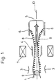
- the electrons propagate on helical paths 8, guided by a static magnetic field 12, from the cathode 1 to the resonator 4 and leave it as a “used” beam. That is, it has completely or largely released its transverse energy in resonator 4.
- the "used” beam finally hits collector 6.
- m ⁇ is the relativistic mass of the electrons with the elementary charge e.
- the detuning between the electron cyclotron frequency and the resonant circuit frequency of the resonator 4 is essential for the interaction in which, depending on the injection phase, a different amount of energy is taken from the transverse speed component.
- the microwave energy is then extracted either in the axial direction 10 of the gyrotron or perpendicular to the gyrotron axis 10.
- the ratio of the energy taken from the transverse speed component to the original energy in the transverse component is called the transverse efficiency ⁇ ⁇ .
- the gyrotron efficiency can be increased by letting the beam strike a biased collector 6.
- the level of the preload compared to the potential against which the electrons can start on average is the collector efficiency ⁇ c .
- the bias In a single-stage biased collector 6, the bias must be less than the potential that corresponds to the energy of the slowest electron.
- the spread of the energy distribution in the "used" beam is extreme strong (see Figure 4 the dashed lines). At lower efficiency levels, the scatter is somewhat weaker, which in both cases only allows low collector efficiency levels.
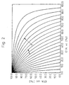
- Fig. 2 shows the family of lines for each constant overall efficiency ⁇ as a function of ⁇ c , ⁇ el .
- the overall efficiency can either be increased by a multi-stage prestressed collector 6 or, on the one hand, by generating as monoenergetic as possible a "consumed” electron beam, which increases ⁇ c . On the other hand, by increasing ⁇ ⁇ . Both a monoenergetic "used" electron beam and / or an increase in ⁇ ⁇ can be achieved if, instead of the constant magnetic field 11 previously used (see dashed lines in FIG. 3), a magnetic field 12 (see FIG. 3) with a monotonous axial dependence in the resonator 4 ) with preferably weak ripple ( ⁇ 3%) along the resonator axis 10.
- Such a magnetic field 12 for short resonator lengths is easier to generate with permanent magnets 7 than with coils (solenoids 7).
- the depth of the ripple can vary along the resonator axis 10.
- the period length is some 10% of the length of the resonator 4.
- Figure 3 shows the above. Field courses 11, 12 over the length of the Resonators 4 from the left conical area (taper 14) over the actual resonator 4 to the right conical area (Taper 15).
- the resonator 4 of the gyrotron is a longitudinal section in principle in Figure 1 and under the diagram of Figure 3 indicated. It was initially accepted for parameter studies.
- the dash-dot line shows the course of the electrical Field distribution 13 along the resonator 4.
- FIG. 4 shows the energy distribution of the electrons in the "consumed beam", ie behind the resonator 4 in the direction of the collector 6.
Landscapes
- Microwave Tubes (AREA)
Description
- Figur 1
- den grundsätzlichen Aufbau des Gyrotrons mit der erfindungsgemäßen Einrichtung zur Erzeugung des statischen, welligen Gleichfelds,
- Figur 2
- ein Schaubild der Linien konstanten Gesamtwirkungsgrads,
- Figur 3
- den Verlauf des Magnetfelds und des elektrischen Felds über der Resonatorlänge und
- Figur 4
- die Energieverteilung der Elektronen im verbrauchten Strahl.
- 1
- Kathode
- 2
- Emitterring
- 3
- Beschleunigungsanode
- 4
- Wechselwirkungsraum, Resonator
- 5
- Auskoppelleitung
- 6
- Kollektor
- 7
- Einrichtung, Solenoid, Permanentmagnet
- 8
- Wendelbewegung, Bahn
- 10
- Gyrotronachse, Resonatorachse
- 11
- konstantes Magnetfeld
- 12
- inhomogenes, welliges Magnetfeld
- 13
- elektrische Feldverteilung
- 14
- Taper
- 15
- Taper
Claims (6)
- Verfahren zur Erhöhung und/oder Sicherstellung des Wirkungsgrads eines Gyrotrons,
dadurch gekennzeichnet, daßeinem die Wendelbewegung (8) der Elektronen erzeugenden statischen Gleichmagnetfeld (11) im Resonatorbereich ein welliges Magnetfeld überlagert wird, mit dem das Verhältnis aus entnommener transversaler Bewegungsenergie zur transversalen Bewegungsenergie vor der Entnahme für die den Resonator (4) durchlaufende Elektronen gleich gehalten wird,die Amplitude der Welligkeit etwa 3 % der Gleichfeldstärke und die Periodenlänge mit einigen 10 % der gesamten Resonatorlänge gewählt wird, wodurch ein monoenergetischer Elektronenstrahl mit keiner transversalen Geschwindigkeitskomponente nach Verlassen des Resonatorraums erzeugt wird, und dadurch Fehlanpassungen von der dem Magnetfeld (11) abhängigen Elektron-Zyklotron-Frequenz an die Resonanzfrequenz des Gyrotronresonators vermieden werden,die im Strahl verbliebene Energie durch einen einstufig vorgespannten Kollektor (6) zurückgewonnen wird. - Gyrotron zur Durchführung des Verfahrens nach Anspruch 1, bestehend aus einer Kathode (1) mit Emittering (2), einer Beschleunigeranode (3), einem Wechselwirkungsraum (Resonator) (4), einer Auskoppelleitung (5) und einem Kollektor (6) sowie einer Einrichtung (7) zur Erzeugung eines solenoidalen, statischen axialen magnetischen Gleichfelds (11),
dadurch gekennzeichnet, daßdie Einrichtung (7) zur Erzeugung des solenoidalen, axialen magnetischen Gleichfelds (12), das die Wendelbewegung der Elektronen erzeugt, derart aufgebaut ist, daß im Bereich des Resonators (4) ein vorgegeben welliger Verlauf mit einer Amplitude von etwa 3 % des Gleichfelds (12) besteht und die Periodenlänge einige 10% der Resonatorlänge beträgt, wodurch alle den Resonator (4) durchlaufenden Elektronen beim Austritt aus dem Resonatorbereich (4) keine transversale Geschwindigkeitskomponente mehr haben,der koaxial zur Gyrotronachse (10) liegende Kollektor (6) derart aufgebaut ist, daß er mit mindestens einer Vorspannung beaufschlagbar ist. - Gyrotron nach Anspruch 2,
dadurch gekennzeichnet, daß die Einrichtung (7) zur Erzeugung des welligen Gleichfelds (12) ein entsprechend räumlich gewickeltes Solenoid (7) ist. - Gyrotron nach Anspruch 2,
dadurch gekennzeichnet, daß die Einrichtung (7) zur Erzeugung des welligen Gleichfelds (12) ein entsprechend geschichteter Permanentmagnet (7) ist. - Gyrotron nach Anspruch 2,
dadurch gekennzeichnet, daß die Einrichtung (7) zur Erzeugung des welligen Gleichfelds (12) ein supraleitendes Solenoid (7) ist. - Gyrotron nach Anspruch 2,
dadurch gekennzeichnet, daß die Einrichtung (7) zur Erzeugung des welligen Gleichfelds (12) ein kombiniertes System aus Permanentmagneten und supra- oder normalleitenden Solenoiden ist.
Applications Claiming Priority (3)
| Application Number | Priority Date | Filing Date | Title |
|---|---|---|---|
| DE4236149 | 1992-10-27 | ||
| DE4236149A DE4236149C2 (de) | 1992-10-27 | 1992-10-27 | Gyrotron mit einer Einrichtung zur Erhöhung des Wirkungsgrads |
| PCT/EP1993/002783 WO1994010699A1 (de) | 1992-10-27 | 1993-10-11 | Verfahren zur erhöhung und/oder sicherstellung des wirkungsgrads eines gyrotrons und gyrotron zur durchführung des verfahrens |
Publications (2)
| Publication Number | Publication Date |
|---|---|
| EP0667033A1 EP0667033A1 (de) | 1995-08-16 |
| EP0667033B1 true EP0667033B1 (de) | 1999-03-03 |
Family
ID=6471399
Family Applications (1)
| Application Number | Title | Priority Date | Filing Date |
|---|---|---|---|
| EP93922546A Expired - Lifetime EP0667033B1 (de) | 1992-10-27 | 1993-10-11 | Verfahren zur erhöhung und/oder sicherstellung des wirkungsgrads eines gyrotrons und gyrotron zur durchführung des verfahrens |
Country Status (5)
| Country | Link |
|---|---|
| US (1) | US5610482A (de) |
| EP (1) | EP0667033B1 (de) |
| JP (1) | JP2904308B2 (de) |
| DE (2) | DE4236149C2 (de) |
| WO (1) | WO1994010699A1 (de) |
Families Citing this family (6)
| Publication number | Priority date | Publication date | Assignee | Title |
|---|---|---|---|---|
| DE4424230C2 (de) * | 1994-07-09 | 1996-08-14 | Karlsruhe Forschzent | Magnetsystem für Gyrotrons |
| US6424090B1 (en) * | 1999-11-12 | 2002-07-23 | Gti | Modification of millimetric wavelength microwave beam power distribution |
| US8390200B2 (en) * | 2005-12-16 | 2013-03-05 | Shenggang Liu | Coaxial cavity gyrotron with two electron beams |
| US7764020B2 (en) * | 2006-07-20 | 2010-07-27 | Barnett Larry R | Electro-permanent magnet for power microwave tubes |
| RU2523447C2 (ru) * | 2012-06-21 | 2014-07-20 | Федеральное государственное бюджетное учреждение науки Институт прикладной физики Российской академии наук(ИПФ РАН), | Электронная пушка магнетронного типа для формирования винтовых электронных пучков с ловушкой отраженных электронов |
| RU2755826C1 (ru) * | 2021-02-04 | 2021-09-22 | Федеральное государственное бюджетное научное учреждение "Федеральный исследовательский центр Институт прикладной физики Российской академии наук" (ИПФ РАН) | Многоствольный гиротрон |
Family Cites Families (9)
| Publication number | Priority date | Publication date | Assignee | Title |
|---|---|---|---|---|
| FR2301903A1 (fr) * | 1975-02-21 | 1976-09-17 | Thomson Csf | Bobinage electrique d'electro-aimant et tube electronique comportant un tel bobinage |
| US4393332A (en) * | 1980-09-05 | 1983-07-12 | Varian Associates, Inc. | Gyrotron transverse energy equalizer |
| US4398121A (en) * | 1981-02-05 | 1983-08-09 | Varian Associates, Inc. | Mode suppression means for gyrotron cavities |
| US4533875A (en) * | 1982-06-16 | 1985-08-06 | Lau Yue Ying | Wide-band gyrotron traveling-wave amplifier |
| US4604551A (en) * | 1983-07-27 | 1986-08-05 | Ga Technologies Inc. | Cyclotron resonance maser system with microwave output window and coupling apparatus |
| US4554483A (en) * | 1983-09-29 | 1985-11-19 | The United States Of America As Represented By The Secretary Of The Navy | Active circulator gyrotron traveling-wave amplifier |
| US4621219A (en) * | 1984-07-17 | 1986-11-04 | Varian Associates, Inc. | Electron beam scrambler |
| JPS63245844A (ja) * | 1987-03-31 | 1988-10-12 | Toshiba Corp | ジヤイロトロン |
| JPH0817081B2 (ja) * | 1988-10-31 | 1996-02-21 | 株式会社東芝 | 超高周波発振管装置 |
-
1992
- 1992-10-27 DE DE4236149A patent/DE4236149C2/de not_active Expired - Fee Related
-
1993
- 1993-10-11 JP JP6510611A patent/JP2904308B2/ja not_active Expired - Lifetime
- 1993-10-11 DE DE59309418T patent/DE59309418D1/de not_active Expired - Fee Related
- 1993-10-11 WO PCT/EP1993/002783 patent/WO1994010699A1/de not_active Ceased
- 1993-10-11 EP EP93922546A patent/EP0667033B1/de not_active Expired - Lifetime
-
1995
- 1995-03-03 US US08/398,653 patent/US5610482A/en not_active Expired - Fee Related
Also Published As
| Publication number | Publication date |
|---|---|
| US5610482A (en) | 1997-03-11 |
| DE59309418D1 (de) | 1999-04-08 |
| DE4236149C2 (de) | 1995-11-02 |
| DE4236149A1 (de) | 1994-05-05 |
| WO1994010699A1 (de) | 1994-05-11 |
| JPH08500933A (ja) | 1996-01-30 |
| JP2904308B2 (ja) | 1999-06-14 |
| EP0667033A1 (de) | 1995-08-16 |
Similar Documents
| Publication | Publication Date | Title |
|---|---|---|
| DE69023602T2 (de) | Synchrotronstrahlungsgerät. | |
| US6914396B1 (en) | Multi-stage cavity cyclotron resonance accelerator | |
| EP2540143B1 (de) | Beschleuniger für geladene teilchen | |
| EP1123642A1 (de) | Plasmabeschleuniger-anordnung | |
| DE3104461A1 (de) | Verfahren zur erzeugung von stark geladenen schweren ionen, vorrichtung zur durchfuehrung des verfahrens und eine verwendung dieses verfahrens | |
| DE69029254T2 (de) | Superleitender linearbeschleuniger mit saphir-kristall | |
| DE3134582C2 (de) | ||
| DE4236149C2 (de) | Gyrotron mit einer Einrichtung zur Erhöhung des Wirkungsgrads | |
| DE68914669T2 (de) | Verfahren in einem impulsbeschleuniger zur beschleunigung eines magnetischen rotierenden plasmas. | |
| DE3525275A1 (de) | Mikrowellenroehre | |
| DE69130913T2 (de) | Quelle starkgeladener Ionen mit polarisierbarer Probe und mit Elektronzyklotronresonanz | |
| DE69737461T2 (de) | Magnetische vorrichtung, insbesondere fuer elektronzyklotronresonanzionenquellen, die die erzeugung geschlossener oberflaechen mit konstanter magnetfeldstaerke b und beliebiger groesse ermoeglichen | |
| Kester et al. | The Frankfurt MEDEBIS: A prototype of an injector for a synchrotron dedicated for cancer therapya | |
| DE69205769T2 (de) | Elektrostatischer Beschleuniger und Freielektronenlaser mit einem solchen Beschleuniger. | |
| DE19750904A1 (de) | Dualenergie-Ionenstrahlbeschleuniger | |
| DE68917081T2 (de) | Hochfrequenz-Oszillator. | |
| DE1491307B2 (de) | Elektronenstrahlerzeugersystem fuer eine laufzeitroehre | |
| DE3315689A1 (de) | Mikrowellen-diode | |
| DE69825218T2 (de) | Optimal entworfene Wanderfeldröhre zum Betrieb unterhalb ihrer Sättigung | |
| DE906707C (de) | Durch Mitnahme stabilisierter, selbstschwingender Ultrakurzwellengenerator, bei welchem eine Elektronenstroemung in einer Generatorstrecke (Leistungsstrecke) Energie an ein Schwingungsfeld abgibt | |
| Bollinger | Superconducting linacs—some recent developments | |
| DE3334520A1 (de) | Linearstrahl-elektronenroehre | |
| Bottollier-Curtet et al. | First FEL experiment in the millimeter range at CESTA The ONDINE experiment | |
| Loew | Properties of a linac-storage ring stretcher system | |
| WO2002071817A1 (en) | Multi-stage cavity cyclotron resonance accelerator |
Legal Events
| Date | Code | Title | Description |
|---|---|---|---|
| PUAI | Public reference made under article 153(3) epc to a published international application that has entered the european phase |
Free format text: ORIGINAL CODE: 0009012 |
|
| 17P | Request for examination filed |
Effective date: 19950216 |
|
| AK | Designated contracting states |
Kind code of ref document: A1 Designated state(s): CH DE FR GB LI |
|
| 17Q | First examination report despatched |
Effective date: 19960605 |
|
| GRAG | Despatch of communication of intention to grant |
Free format text: ORIGINAL CODE: EPIDOS AGRA |
|
| GRAG | Despatch of communication of intention to grant |
Free format text: ORIGINAL CODE: EPIDOS AGRA |
|
| GRAH | Despatch of communication of intention to grant a patent |
Free format text: ORIGINAL CODE: EPIDOS IGRA |
|
| GRAH | Despatch of communication of intention to grant a patent |
Free format text: ORIGINAL CODE: EPIDOS IGRA |
|
| RAP1 | Party data changed (applicant data changed or rights of an application transferred) |
Owner name: FORSCHUNGSZENTRUM KARLSRUHE GMBH |
|
| GRAA | (expected) grant |
Free format text: ORIGINAL CODE: 0009210 |
|
| AK | Designated contracting states |
Kind code of ref document: B1 Designated state(s): CH DE FR GB LI |
|
| REG | Reference to a national code |
Ref country code: CH Ref legal event code: NV Representative=s name: ROTTMANN, ZIMMERMANN + PARTNER AG Ref country code: CH Ref legal event code: EP |
|
| REF | Corresponds to: |
Ref document number: 59309418 Country of ref document: DE Date of ref document: 19990408 |
|
| ET | Fr: translation filed | ||
| GBT | Gb: translation of ep patent filed (gb section 77(6)(a)/1977) |
Effective date: 19990528 |
|
| PLBE | No opposition filed within time limit |
Free format text: ORIGINAL CODE: 0009261 |
|
| STAA | Information on the status of an ep patent application or granted ep patent |
Free format text: STATUS: NO OPPOSITION FILED WITHIN TIME LIMIT |
|
| 26N | No opposition filed | ||
| PGFP | Annual fee paid to national office [announced via postgrant information from national office to epo] |
Ref country code: GB Payment date: 20000822 Year of fee payment: 8 |
|
| PGFP | Annual fee paid to national office [announced via postgrant information from national office to epo] |
Ref country code: FR Payment date: 20001030 Year of fee payment: 8 |
|
| PGFP | Annual fee paid to national office [announced via postgrant information from national office to epo] |
Ref country code: CH Payment date: 20010430 Year of fee payment: 8 |
|
| PG25 | Lapsed in a contracting state [announced via postgrant information from national office to epo] |
Ref country code: GB Free format text: LAPSE BECAUSE OF NON-PAYMENT OF DUE FEES Effective date: 20011011 |
|
| PG25 | Lapsed in a contracting state [announced via postgrant information from national office to epo] |
Ref country code: LI Free format text: LAPSE BECAUSE OF NON-PAYMENT OF DUE FEES Effective date: 20011031 Ref country code: CH Free format text: LAPSE BECAUSE OF NON-PAYMENT OF DUE FEES Effective date: 20011031 |
|
| REG | Reference to a national code |
Ref country code: GB Ref legal event code: IF02 |
|
| GBPC | Gb: european patent ceased through non-payment of renewal fee |
Effective date: 20011011 |
|
| REG | Reference to a national code |
Ref country code: CH Ref legal event code: PL |
|
| PG25 | Lapsed in a contracting state [announced via postgrant information from national office to epo] |
Ref country code: FR Free format text: LAPSE BECAUSE OF NON-PAYMENT OF DUE FEES Effective date: 20020628 |
|
| REG | Reference to a national code |
Ref country code: FR Ref legal event code: ST |
|
| PGFP | Annual fee paid to national office [announced via postgrant information from national office to epo] |
Ref country code: DE Payment date: 20020911 Year of fee payment: 10 |
|
| PG25 | Lapsed in a contracting state [announced via postgrant information from national office to epo] |
Ref country code: DE Free format text: LAPSE BECAUSE OF NON-PAYMENT OF DUE FEES Effective date: 20040501 |