EP0666614B1 - Bimetall-Verbinder - Google Patents
Bimetall-Verbinder Download PDFInfo
- Publication number
- EP0666614B1 EP0666614B1 EP95500008A EP95500008A EP0666614B1 EP 0666614 B1 EP0666614 B1 EP 0666614B1 EP 95500008 A EP95500008 A EP 95500008A EP 95500008 A EP95500008 A EP 95500008A EP 0666614 B1 EP0666614 B1 EP 0666614B1
- Authority
- EP
- European Patent Office
- Prior art keywords
- connector
- blade
- opposite
- intermediate portion
- aluminium
- Prior art date
- Legal status (The legal status is an assumption and is not a legal conclusion. Google has not performed a legal analysis and makes no representation as to the accuracy of the status listed.)
- Expired - Lifetime
Links
Images


Classifications
-
- H—ELECTRICITY
- H01—ELECTRIC ELEMENTS
- H01R—ELECTRICALLY-CONDUCTIVE CONNECTIONS; STRUCTURAL ASSOCIATIONS OF A PLURALITY OF MUTUALLY-INSULATED ELECTRICAL CONNECTING ELEMENTS; COUPLING DEVICES; CURRENT COLLECTORS
- H01R4/00—Electrically-conductive connections between two or more conductive members in direct contact, i.e. touching one another; Means for effecting or maintaining such contact; Electrically-conductive connections having two or more spaced connecting locations for conductors and using contact members penetrating insulation
- H01R4/58—Electrically-conductive connections between two or more conductive members in direct contact, i.e. touching one another; Means for effecting or maintaining such contact; Electrically-conductive connections having two or more spaced connecting locations for conductors and using contact members penetrating insulation characterised by the form or material of the contacting members
- H01R4/62—Connections between conductors of different materials; Connections between or with aluminium or steel-core aluminium conductors
- H01R4/625—Soldered or welded connections
-
- H—ELECTRICITY
- H01—ELECTRIC ELEMENTS
- H01R—ELECTRICALLY-CONDUCTIVE CONNECTIONS; STRUCTURAL ASSOCIATIONS OF A PLURALITY OF MUTUALLY-INSULATED ELECTRICAL CONNECTING ELEMENTS; COUPLING DEVICES; CURRENT COLLECTORS
- H01R4/00—Electrically-conductive connections between two or more conductive members in direct contact, i.e. touching one another; Means for effecting or maintaining such contact; Electrically-conductive connections having two or more spaced connecting locations for conductors and using contact members penetrating insulation
- H01R4/58—Electrically-conductive connections between two or more conductive members in direct contact, i.e. touching one another; Means for effecting or maintaining such contact; Electrically-conductive connections having two or more spaced connecting locations for conductors and using contact members penetrating insulation characterised by the form or material of the contacting members
- H01R4/66—Connections with the terrestrial mass, e.g. earth plate, earth pin
Definitions
- the invention relates to a bimetallic connector, for electrical and earth connections, comprising an aluminium part and a copper part attached together by a copper-aluminium bimetallic joining system and which extend in opposite directions from the joint, which is located in an intermediate portion adapted for attachment to connector holding means.
- the aluminium part is provided with a first blade and the copper part is provided with a second blade.
- a bimetallic connector in which both the copper part and the aluminium part comprise opposite half round end portions.
- this known connector is held by a clamp applied to the intermediate portion thereof, in such a way that the curved surface of each of the end portions is adjacent the vertical surface. It is obvious, therefore, that there is no useful space between the connector and the vertical wall and consequently it is not possible to locate either a nut or the head of a screw.
- the known connector has to be provided with threaded holes capable of receiving and retaining screws which also pass through the corresponding copper and aluminium bars.
- a connector of the type described at the beginning which is characterized in that said first blade: (a) occupies a substantially axially centered wide area; (b) has two substantially parallel opposite surfaces forming a thickness smaller than that of the said intermediate portion; and (c) is provided with at least one not threaded passage extending between said opposite surfaces.
- first connector blade of the invention Since the first connector blade of the invention is centered and is thinner than the intermediate section, there is of necessity a free space behind the first blade when the connector is installed and this free space allows either the head of screw or a nut to be fitted, whereby the connection with an aluminium bar may also be made without the need for screw threads, with standardized easily obtainable items, such as screws, nuts and, as required, washers. It should be noted that a connection made with screws, nuts and washers is considered to be one of the most reliable.
- said second blade is substantially axially offset; it has two substantially flat opposite flats parallel to said opposite surfaces and is provided with at least one hole extending between said opposite flats.
- said second blade is substantially axially centered, whereby it allows other copper blades in a similar way to the aluminium blades to be used.
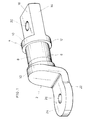
- Figure 1 is a perspective view of one embodiment of the connector of the invention.
- Figure 2 is a side elevation view on a smaller scale.
- Figure 3 is a plan view from above, also on a smaller scale.
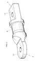
- Figure 4 is a perspective view of a second embodiment of the present connector.
- Figure 5 is a side elevation view of the latter on a smaller scale.
- Figure 6 is a plan view from above of the second connector, also on a smaller scale.
- the bimetallic connector comprises a copper part 2 and an aluminium part 4 connected together by friction welding or any other system of forming copper-aluminium bimetallic joints.
- the joint may be appreciated by the line 6, from which the two parts 2, 4 extend in opposite directions.
- the joint is located in an intermediate portion 8 which is preferably cylindrical or prismatic, whereby it defines generating lines.
- the form and thickness of the intermediate portion 8 make it suitable for attachment to holding means, preferably a standardized circular clamp, not shown.
- the intermediate portion 8 be located between two widened portions 10 which facilitate the fitting and permanent location of the said clamp and that the side surface 12 of each widened portion 10 be substantially perpendicular to the generating lines of the intermediate portion.
- the aluminium part 4 is provided with a first blade 14 for connection to a flat bar (not shown) which is generally made from aluminium, although it may be made from any other material.
- the first blade 14 has two opposite parallel surfaces 16 with the distance between them being substantially less than the thickness of the intermediate portion and, therefore, less than the diameter of the widened portions 10. Therefore, between one surface 16 and the most outwardly extending portion of the respective widened portion 10 there is a space to be referred to hereinafter.
- the first blade 14 is substantially axially centered, i.e. the two heights 18 shown in Figure 2 are substantially the same.
- the blade 14 is also provided with at least one passage 20 extending between both surfaces 16 and is suitable for receiving a screw, pin, bolt or the like.
- the copper part 2 is provided in turn with a second blade 22 for connection to a flat bar which is generally made from copper, although it may be made from any other material. This bar is not shown either.
- This second blade is also provided with two opposite substantially plane flats 24 which are substantially parallel to the surfaces 16 of the first blade 14.
- the second blade 22 is seen to be substantially axially offset, like some already known forged blades. In the embodiment described, it is provided with an orifice 26 extending between said opposite flats and which, like the passage 20, is suitable for receiving a screw, pin, bolt or the like.
- the configuration of the first blade 14 and the said space formed from each surface 16 allow a nut or the head of screw to be inserted, which greatly facilitates its use.
- the aluminium blade 4 and the centre portion 8 have a configuration substantially the same as that of the embodiment already described.
- the copper blade 22 is substantially centered, in a similar way to the aluminium blade 14. Therefore, in this case, the two heights 28 shown in Figure 5 are also substantially the same.
- the clarity of Figures 4 to 6 and the similarities with the embodiment of the first three Figures make any further description unnecessary.
- the connector of the invention may also be used as a bimetallic connection between aluminium and copper cables and busbar terminations.
Claims (6)
- Zweimetallverbinder für elektrische Erdungsanschlüsse mit einem Aluminiumteil (4) und einem Kupferteil (2), die über eine Kupfer-Aluminium-Bimetallverbindungseinheit miteinander verbunden sind und sich von der Verbindungsstelle aus in entgegengesetzte Richtungen erstrecken, wobei die Verbindungsstelle in einem Zwischenbereich (8) angeordnet ist und für das Anbringen von Verbinder-Halteeinrichtungen angepaßt ist, wobei das Aluminiumteil (4) mit einem ersten Blatt (14) und das Kupferteil (2) mit einem zweiten Blatt (22) versehen ist,
dadurch gekennzeichnet, daß
das erste Blatt (14):(a) eine im wesentlichen axial zentrierte große Fläche einnimmt,(b) zwei im wesentlichen parallele gegenüberliegende Oberflächen (16) aufweist, wobei deren Dicke kleiner ist als der Zwischenbereich (8), und(c) mit mindestens einem kein Gewinde aufweisenden Durch: gang (20) versehen ist, der sich zwischen den gegenüberliegenden Oberflächen (16) erstreckt. - Zweimetallverbinder nach Anspruch 1,
dadurch gekennzeichnet, daß
die Verbindungseinheit durch Reibschweißen erzeugt wird. - Zweimetallverbinder nach Anspruch 1 oder 2,
dadurch gekennzeichnet, daß
das zweite Blatt (22) zur Achse versetzt und mit zwei im wesentlichen flachen gegenüberliegenden Flächen (24) versehen ist, die zu den gegenüberliegenden Oberflächen (16) parallel sind und mit mindestens einer Öffnung (26) versehen sind, die sich zwischen den Ebenen (24) erstreckt. - Zweimetallverbinder nach Anspruch 1 oder 2,
dadurch gekennzeichnet, daß
das zweite Blatt (22) im wesentlichen zur Achse ausgerichtet und mit zwei im wesentlichen flachen gegenüberliegenden Ebenen (24) versehen ist, die zu den gegenüberliegenden Oberflächen (16) parallel sind und mit mindestens einer Öffnung (26) versehen sind, die sich zwischen den gegenüberliegenden Ebenen (24) erstreckt. - Zweimetallverbinder nach einem der Ansprüche 1 bis 4,
dadurch gekennzeichnet, daß
der Zwischenbereich (8) im wesentlichen zylindrisch oder prismatisch ist und zwischen zwei geweiteten Teilen (10) des Verbindungsstücks angeordnet ist. - Zweimetallverbinder nach Anspruch 5,
dadurch gekennzeichnet, daß
die Seitenflächen (12) jedes der geweiteten Teile (10) an den Zwischenbereich (8) grenzen und Ebenen beschreiben, die zu den von dem Zwischenbereich (8) erzeugten Linien im wesentlichen senkrecht stehen.
Applications Claiming Priority (2)
| Application Number | Priority Date | Filing Date | Title |
|---|---|---|---|
| ES9400210 | 1994-02-07 | ||
| ES09400210A ES2085827B1 (es) | 1994-02-07 | 1994-02-07 | Conector bimetalico. |
Publications (2)
| Publication Number | Publication Date |
|---|---|
| EP0666614A1 EP0666614A1 (de) | 1995-08-09 |
| EP0666614B1 true EP0666614B1 (de) | 1998-08-26 |
Family
ID=8285119
Family Applications (1)
| Application Number | Title | Priority Date | Filing Date |
|---|---|---|---|
| EP95500008A Expired - Lifetime EP0666614B1 (de) | 1994-02-07 | 1995-01-30 | Bimetall-Verbinder |
Country Status (4)
| Country | Link |
|---|---|
| EP (1) | EP0666614B1 (de) |
| CN (1) | CN1050704C (de) |
| DE (1) | DE69504216T2 (de) |
| ES (1) | ES2085827B1 (de) |
Families Citing this family (11)
| Publication number | Priority date | Publication date | Assignee | Title |
|---|---|---|---|---|
| DE19941429A1 (de) * | 1999-08-30 | 2001-02-08 | Sefag Ag Malters | Kopfarmatur für Hochspannungs-Kabelendverschlüsse |
| US7947904B2 (en) | 2005-04-01 | 2011-05-24 | Autonetworks Technologies, Ltd. | Conductor and wire harness |
| DE102006062850B4 (de) * | 2006-07-07 | 2013-03-28 | Auto-Kabel Managementgesellschaft Mbh | Elektrisches Kontaktelement |
| FR2925773B1 (fr) * | 2007-12-21 | 2010-03-12 | Valeo Systemes De Liaison | Assemblage comportant une batterie et un conducteur relies par un plot, notamment traversant une cloison |
| WO2010031857A2 (de) * | 2008-09-18 | 2010-03-25 | Magna Steyr Fahrzeugtechnik Ag & Co Kg | Kühleinheit |
| WO2010037799A2 (de) | 2008-09-30 | 2010-04-08 | Magna Steyr Fahrzeugtechnik Ag & Co Kg | Energiespeichereinheit |
| CN102136638B (zh) * | 2011-01-19 | 2012-11-21 | 安徽省电力公司合肥供电公司 | 电气接头 |
| CN103825111B (zh) * | 2014-03-12 | 2016-03-16 | 兴盛电器股份有限公司 | 电容补偿接触器上下连接结构 |
| DE102014011887A1 (de) * | 2014-08-13 | 2016-02-18 | Auto-Kabel Management Gmbh | Elektrisches Anschlusselement, Verfahren zur Herstellung eines elektrischen Anschlusselements sowie Verwendung eines elektrischen Anschlusselements |
| CN110492265A (zh) * | 2019-08-23 | 2019-11-22 | 上海宝冶市政工程有限公司 | 一种接地线夹 |
| DE102022109502B4 (de) | 2022-04-20 | 2023-11-09 | Auto-Kabel Management Gmbh | Bimetallischer Ladekabelsteckverbinder, Verfahren zur Herstellung eines Ladekabelsteckverbinders, Ladebuchse mit einem Ladekabelsteckverbinder sowie System mit einem Ladekabelsteckverbinder |
Family Cites Families (5)
| Publication number | Priority date | Publication date | Assignee | Title |
|---|---|---|---|---|
| DE625428C (de) * | 1934-11-15 | 1936-02-11 | Wilhelm Hofmann Fa J | Klemme zum Verbinden elektrischer Leiter aus verschiedenen Metallen |
| FR1289476A (fr) * | 1960-12-28 | 1962-04-06 | Materiel Electr Soc Ind De | Objets métalliques hétérogènes pour raccordements électriques et procédé pourles façonner |
| US3973823A (en) * | 1974-09-06 | 1976-08-10 | Square D Company | Electrical terminal connector |
| US4334122A (en) * | 1980-06-25 | 1982-06-08 | General Electric Company | Bimetallic electrical connector and method for making such connector |
| DE3539622A1 (de) * | 1985-11-08 | 1987-05-14 | Felten & Guilleaume Energie | Verbinder fuer den uebergang eines kupferleiters auf einen aluminiumleiter |
-
1994
- 1994-02-07 ES ES09400210A patent/ES2085827B1/es not_active Expired - Fee Related
-
1995
- 1995-01-30 DE DE69504216T patent/DE69504216T2/de not_active Expired - Fee Related
- 1995-01-30 EP EP95500008A patent/EP0666614B1/de not_active Expired - Lifetime
- 1995-02-07 CN CN95102917A patent/CN1050704C/zh not_active Expired - Fee Related
Also Published As
| Publication number | Publication date |
|---|---|
| ES2085827A2 (es) | 1996-06-01 |
| DE69504216T2 (de) | 1999-02-25 |
| ES2085827B1 (es) | 1998-03-01 |
| ES2085827R (de) | 1997-07-01 |
| CN1050704C (zh) | 2000-03-22 |
| CN1113039A (zh) | 1995-12-06 |
| DE69504216D1 (de) | 1998-10-01 |
| EP0666614A1 (de) | 1995-08-09 |
Similar Documents
| Publication | Publication Date | Title |
|---|---|---|
| EP0666614B1 (de) | Bimetall-Verbinder | |
| CA1234196A (en) | Electric tap connector | |
| US5620291A (en) | Quick disconnect fastener | |
| US5720567A (en) | Cable tray system | |
| US5765962A (en) | Ground rod connector | |
| US5188544A (en) | Electrical conductor terminal apparatus and method | |
| US7803001B2 (en) | Ground connector | |
| US4784621A (en) | Wire connector | |
| US10109932B2 (en) | Electrical clamps | |
| PL175306B1 (pl) | Klinowe złącze uziemiające | |
| CN1028694C (zh) | 电缆夹具 | |
| US5342224A (en) | Parallel street light tap connector | |
| US4840581A (en) | Cable jacket strain relief adapter assembly | |
| US20230003248A1 (en) | Bonding washer | |
| US4105272A (en) | High current grounding assembly having rigid interconnecting conductors | |
| CA1081337A (en) | Keyhole grounding clamp | |
| US6325678B1 (en) | Electrical clamp connector | |
| KR100361083B1 (ko) | 애자용 전선 고정장치 | |
| US20020090847A1 (en) | Ground connector | |
| JP2912942B2 (ja) | 避雷導線の鉄筋接続金具と避雷導線集結金具 | |
| JPH044808B2 (de) | ||
| KR200156698Y1 (ko) | 가공지선 지지대 | |
| US20030157822A1 (en) | Modular ground bar system | |
| KR200214341Y1 (ko) | 애자용 전선 고정장치 | |
| KR200214750Y1 (ko) | 애자용 전선 고정장치 |
Legal Events
| Date | Code | Title | Description |
|---|---|---|---|
| PUAI | Public reference made under article 153(3) epc to a published international application that has entered the european phase |
Free format text: ORIGINAL CODE: 0009012 |
|
| AK | Designated contracting states |
Kind code of ref document: A1 Designated state(s): BE DE ES FR GB IT |
|
| 17P | Request for examination filed |
Effective date: 19960125 |
|
| GRAG | Despatch of communication of intention to grant |
Free format text: ORIGINAL CODE: EPIDOS AGRA |
|
| GRAG | Despatch of communication of intention to grant |
Free format text: ORIGINAL CODE: EPIDOS AGRA |
|
| GRAH | Despatch of communication of intention to grant a patent |
Free format text: ORIGINAL CODE: EPIDOS IGRA |
|
| 17Q | First examination report despatched |
Effective date: 19980122 |
|
| GRAH | Despatch of communication of intention to grant a patent |
Free format text: ORIGINAL CODE: EPIDOS IGRA |
|
| GRAA | (expected) grant |
Free format text: ORIGINAL CODE: 0009210 |
|
| AK | Designated contracting states |
Kind code of ref document: B1 Designated state(s): BE DE ES FR GB IT |
|
| PG25 | Lapsed in a contracting state [announced via postgrant information from national office to epo] |
Ref country code: ES Free format text: THE PATENT HAS BEEN ANNULLED BY A DECISION OF A NATIONAL AUTHORITY Effective date: 19980826 |
|
| REF | Corresponds to: |
Ref document number: 69504216 Country of ref document: DE Date of ref document: 19981001 |
|
| ET | Fr: translation filed | ||
| PLBE | No opposition filed within time limit |
Free format text: ORIGINAL CODE: 0009261 |
|
| STAA | Information on the status of an ep patent application or granted ep patent |
Free format text: STATUS: NO OPPOSITION FILED WITHIN TIME LIMIT |
|
| 26N | No opposition filed | ||
| PGFP | Annual fee paid to national office [announced via postgrant information from national office to epo] |
Ref country code: FR Payment date: 20011226 Year of fee payment: 8 |
|
| REG | Reference to a national code |
Ref country code: GB Ref legal event code: IF02 |
|
| PGFP | Annual fee paid to national office [announced via postgrant information from national office to epo] |
Ref country code: BE Payment date: 20020116 Year of fee payment: 8 |
|
| PGFP | Annual fee paid to national office [announced via postgrant information from national office to epo] |
Ref country code: GB Payment date: 20020130 Year of fee payment: 8 |
|
| PGFP | Annual fee paid to national office [announced via postgrant information from national office to epo] |
Ref country code: DE Payment date: 20020328 Year of fee payment: 8 |
|
| PG25 | Lapsed in a contracting state [announced via postgrant information from national office to epo] |
Ref country code: GB Free format text: LAPSE BECAUSE OF NON-PAYMENT OF DUE FEES Effective date: 20030130 |
|
| PG25 | Lapsed in a contracting state [announced via postgrant information from national office to epo] |
Ref country code: BE Free format text: LAPSE BECAUSE OF NON-PAYMENT OF DUE FEES Effective date: 20030131 |
|
| PG25 | Lapsed in a contracting state [announced via postgrant information from national office to epo] |
Ref country code: DE Free format text: LAPSE BECAUSE OF NON-PAYMENT OF DUE FEES Effective date: 20030801 |
|
| GBPC | Gb: european patent ceased through non-payment of renewal fee | ||
| PG25 | Lapsed in a contracting state [announced via postgrant information from national office to epo] |
Ref country code: FR Free format text: LAPSE BECAUSE OF NON-PAYMENT OF DUE FEES Effective date: 20030930 |
|
| REG | Reference to a national code |
Ref country code: FR Ref legal event code: ST |
|
| PG25 | Lapsed in a contracting state [announced via postgrant information from national office to epo] |
Ref country code: IT Free format text: LAPSE BECAUSE OF NON-PAYMENT OF DUE FEES;WARNING: LAPSES OF ITALIAN PATENTS WITH EFFECTIVE DATE BEFORE 2007 MAY HAVE OCCURRED AT ANY TIME BEFORE 2007. THE CORRECT EFFECTIVE DATE MAY BE DIFFERENT FROM THE ONE RECORDED. Effective date: 20050130 |