EP0666424B1 - Fan with rotor, in particular a radial fan rotor - Google Patents
Fan with rotor, in particular a radial fan rotor Download PDFInfo
- Publication number
- EP0666424B1 EP0666424B1 EP95101408A EP95101408A EP0666424B1 EP 0666424 B1 EP0666424 B1 EP 0666424B1 EP 95101408 A EP95101408 A EP 95101408A EP 95101408 A EP95101408 A EP 95101408A EP 0666424 B1 EP0666424 B1 EP 0666424B1
- Authority
- EP
- European Patent Office
- Prior art keywords
- carrier
- fan
- fan according
- air guiding
- guiding element
- Prior art date
- Legal status (The legal status is an assumption and is not a legal conclusion. Google has not performed a legal analysis and makes no representation as to the accuracy of the status listed.)
- Expired - Lifetime
Links
Images


Classifications
-
- H—ELECTRICITY
- H02—GENERATION; CONVERSION OR DISTRIBUTION OF ELECTRIC POWER
- H02K—DYNAMO-ELECTRIC MACHINES
- H02K29/00—Motors or generators having non-mechanical commutating devices, e.g. discharge tubes or semiconductor devices
- H02K29/06—Motors or generators having non-mechanical commutating devices, e.g. discharge tubes or semiconductor devices with position sensing devices
-
- F—MECHANICAL ENGINEERING; LIGHTING; HEATING; WEAPONS; BLASTING
- F04—POSITIVE - DISPLACEMENT MACHINES FOR LIQUIDS; PUMPS FOR LIQUIDS OR ELASTIC FLUIDS
- F04D—NON-POSITIVE-DISPLACEMENT PUMPS
- F04D25/00—Pumping installations or systems
- F04D25/02—Units comprising pumps and their driving means
- F04D25/06—Units comprising pumps and their driving means the pump being electrically driven
- F04D25/0606—Units comprising pumps and their driving means the pump being electrically driven the electric motor being specially adapted for integration in the pump
- F04D25/0653—Units comprising pumps and their driving means the pump being electrically driven the electric motor being specially adapted for integration in the pump the motor having a plane air gap, e.g. disc-type
-
- F—MECHANICAL ENGINEERING; LIGHTING; HEATING; WEAPONS; BLASTING
- F04—POSITIVE - DISPLACEMENT MACHINES FOR LIQUIDS; PUMPS FOR LIQUIDS OR ELASTIC FLUIDS
- F04D—NON-POSITIVE-DISPLACEMENT PUMPS
- F04D29/00—Details, component parts, or accessories
- F04D29/26—Rotors specially for elastic fluids
- F04D29/28—Rotors specially for elastic fluids for centrifugal or helico-centrifugal pumps for radial-flow or helico-centrifugal pumps
- F04D29/281—Rotors specially for elastic fluids for centrifugal or helico-centrifugal pumps for radial-flow or helico-centrifugal pumps for fans or blowers
-
- F—MECHANICAL ENGINEERING; LIGHTING; HEATING; WEAPONS; BLASTING
- F04—POSITIVE - DISPLACEMENT MACHINES FOR LIQUIDS; PUMPS FOR LIQUIDS OR ELASTIC FLUIDS
- F04D—NON-POSITIVE-DISPLACEMENT PUMPS
- F04D29/00—Details, component parts, or accessories
- F04D29/60—Mounting; Assembling; Disassembling
- F04D29/62—Mounting; Assembling; Disassembling of radial or helico-centrifugal pumps
- F04D29/624—Mounting; Assembling; Disassembling of radial or helico-centrifugal pumps especially adapted for elastic fluid pumps
- F04D29/626—Mounting or removal of fans
-
- H—ELECTRICITY
- H02—GENERATION; CONVERSION OR DISTRIBUTION OF ELECTRIC POWER
- H02K—DYNAMO-ELECTRIC MACHINES
- H02K21/00—Synchronous motors having permanent magnets; Synchronous generators having permanent magnets
- H02K21/12—Synchronous motors having permanent magnets; Synchronous generators having permanent magnets with stationary armatures and rotating magnets
- H02K21/24—Synchronous motors having permanent magnets; Synchronous generators having permanent magnets with stationary armatures and rotating magnets with magnets axially facing the armatures, e.g. hub-type cycle dynamos
-
- H—ELECTRICITY
- H02—GENERATION; CONVERSION OR DISTRIBUTION OF ELECTRIC POWER
- H02K—DYNAMO-ELECTRIC MACHINES
- H02K3/00—Details of windings
- H02K3/46—Fastening of windings on the stator or rotor structure
- H02K3/52—Fastening salient pole windings or connections thereto
- H02K3/521—Fastening salient pole windings or connections thereto applicable to stators only
- H02K3/525—Annular coils, e.g. for cores of the claw-pole type
-
- H—ELECTRICITY
- H02—GENERATION; CONVERSION OR DISTRIBUTION OF ELECTRIC POWER
- H02K—DYNAMO-ELECTRIC MACHINES
- H02K5/00—Casings; Enclosures; Supports
- H02K5/04—Casings or enclosures characterised by the shape, form or construction thereof
- H02K5/22—Auxiliary parts of casings not covered by groups H02K5/06-H02K5/20, e.g. shaped to form connection boxes or terminal boxes
- H02K5/225—Terminal boxes or connection arrangements
-
- H—ELECTRICITY
- H02—GENERATION; CONVERSION OR DISTRIBUTION OF ELECTRIC POWER
- H02K—DYNAMO-ELECTRIC MACHINES
- H02K7/00—Arrangements for handling mechanical energy structurally associated with dynamo-electric machines, e.g. structural association with mechanical driving motors or auxiliary dynamo-electric machines
- H02K7/14—Structural association with mechanical loads, e.g. with hand-held machine tools or fans
-
- H—ELECTRICITY
- H02—GENERATION; CONVERSION OR DISTRIBUTION OF ELECTRIC POWER
- H02K—DYNAMO-ELECTRIC MACHINES
- H02K2211/00—Specific aspects not provided for in the other groups of this subclass relating to measuring or protective devices or electric components
- H02K2211/03—Machines characterised by circuit boards, e.g. pcb
-
- H—ELECTRICITY
- H02—GENERATION; CONVERSION OR DISTRIBUTION OF ELECTRIC POWER
- H02K—DYNAMO-ELECTRIC MACHINES
- H02K5/00—Casings; Enclosures; Supports
Definitions
- the invention relates to a fan with a fan wheel, which is arranged on the permanent magnetic rotor of a collectorless DC motor.
- Such a fan is known from DE-U-8 702 271.
- this fan has a relatively large number of individual parts and an excessive height.
- a fan of this type is also described in US-A-5 176 509. Although this fan has a simplified structure, it is also too high in the axial direction.
- the above-mentioned and other known fans can be used with relative can be mounted on a printed circuit board at great expense, but cannot be assembled directly on a printed circuit board like other components (resistors, transistors, capacitors, etc.) and then sent through a solder bath.
- the object of the invention is to further simplify the design of a fan of the aforementioned type and to design it in such a way that the completely assembled fan, like other components, can be fitted directly onto a printed circuit board or the like.
- a fan with a fan wheel which is designed as part of the rotor of a brushless DC motor provided with a rotor magnet, with a stator arrangement which has a carrier for a stator winding, which stator winding has at least one drive winding and one for controlling the commutation Sensor winding has, with a bearing support tube attached to the carrier for receiving a bearing arrangement for the shaft of the fan wheel, with a magnetic arrangement provided on the outside of the bearing support tube for generating a magnetic auxiliary torque in cooperation with the rotor magnet, with a ferromagnetic element provided on the carrier as a magnetic yoke for the rotor magnet, and with fastening means provided on the carrier for fastening the carrier on a printed circuit board or the like, and with electrical connections provided on the carrier for the at least a drive winding and the sensor winding for the electrical connection of these windings with drive electronics of the motor provided on the printed circuit board or the like.
- the construction according to the invention makes it possible to apply the fully assembled fan, for example, to a printed circuit board of a device or the like, for example by means of a snap or plug connection, and then to walk through the soldering bath with the printed circuit board and to close the electrical connections of the windings to the printed circuit board connect, which further simplifies assembly.
- stator carrier which is preferably designed as a plastic molding, and the electrical connections contained in the molding (for example, injected connecting pins) enable automated production, ie the winding, attaching, soldering and testing can be carried out on a machine.
- the plastic molding according to the invention can also be manufactured fully automatically without manually inserting the connecting pins and the yoke element.
- the capped design of the radial fan wheel enables not only the low overall height but also better guidance of the air flow.
- the construction of the fan according to the invention extends the application and fastening options. Further details and advantageous developments of the invention result from the exemplary embodiments described below and shown in the drawing and from the subclaims.
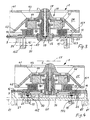
- a fan 1 is shown in a view from below.
- This view shows a carrier 12 which is designed as a plastic molding.
- Electrical connections 16, for example in the form of connecting pins, and guide pins 51; 52 are arranged in the molded part 12, preferably injected.
- These injected or inserted connecting pins 16 consist of electrically conductive material, for example of metal.
- One end 161 of the pins 16 is conductively connected to one end of the winding wires 9 and the other end 162 of the pins 16 protrudes from the carrier 12.
- These ends 162 are plugged into the openings or depressions of a printed circuit board 20 (shown in dash-dot lines) and soldered, ie connected in contacting manner with the drive electronics for the motor 10 of the fan 1.
- the connecting pins 16 are preferably formed at right angles, with one end 161 being arranged in the plane of the carrier 12, which is essentially designed as a flat part, and the end 162 protruding substantially at right angles from the carrier 12.
- the guide pins 51; 52 preferably also formed as right-angled pins made of an electrically conductive material, one end 151; 152 lie in the plane of the carrier 12 and the other ends 153; 154 protrude from the carrier 12 in substantially the same length and parallel to the other ends 162 of the connecting pins 16.
- a yoke element 17 for a rotor magnet 45 in the exemplary embodiment a ferromagnetic sheet-metal disk in the form of a circular ring, is also injected into the molded part 12.
- Fastening means 15 for example in the form of slotted snap bolts, are injection molded onto the underside of the shaped piece.
- the fastening means serve as an assembly aid or for fastening the fan 1 to a printed circuit board 20, which is indicated by dash-dotted lines in FIG. 2.
- Spacer bolts 15 are attached, preferably also molded, on the underside of the molded part 12, which are used to maintain a distance between the underside of the molded part 12 and the plate 20 or which can be used as fitting or guide bolts.
- the above-described configuration of the stator, in particular of the stator carrier 12 enables largely automated production, ie the winding, attaching and applying the winding ends to the pins 16, and soldering and testing can be carried out on an automatic machine.
- FIG. 2 shows in section along the line II-II in FIG. 1 details of the exemplary embodiment according to FIG. 1.
- a stator winding 13 is applied, which and has a sensor winding.
- the shaft 5 is supported radially in a bearing arrangement 34.
- the bearing arrangement 34 for example a double sintered bearing, is fastened in a bearing support tube 14.
- the bearing arrangement 34 can also be designed as a roller bearing.
- the bearing support tube 14 is preferably also part of the molded part 12.
- the sintered bearing 34 can also be Caulking u. Attach.
- a magnetic auxiliary arrangement 18 (ferromagnetic or permanent magnetic arrangement) is fastened in the region of the upper edge 8. To further reduce costs, this auxiliary arrangement 18 can be designed as a disk stamped from rubber-magnetic material.
- a bearing shell 6 inserted into the bearing support tube 14 forms the axial bearing of the shaft 5. The arrangement of the bearing shell 6 determines the size of the essentially flat air gap 7 between a rotor magnet 45 and a stator winding 13.
- This simple and extremely cost-effective collectorless DC motor 10 has, as already known from DE-GM 87 02 271, only one stator winding, which consists of a drive winding and a sensor winding and is preferably wound bifilar. To avoid lengths, reference is made to the content of DE-GM 87 02 271 with regard to the shape of the winding and the circuit.
- the fan wheel 11 contains essentially radially extending blades 21 which are arranged between a first guide member 41 and a second guide member 42.
- the first guide member 41 has a central air inlet opening 43 and is essentially flat.
- the first and second air guide member 41; 42 seen in the axial cross section, form an air outlet cross section which widens outward in this exemplary embodiment.
- a narrowing cross-section and various cross-sectional shapes can also be designed for other applications.
- a ferromagnetic yoke 44 is fastened in the second air guide member 42, on which the rotor magnet 45 for the motor drive of the fan wheel 11 is arranged.
- a pole-oriented magnet without a yoke can also be used.
- the electrical components (transistors, resistors, etc.) for the motor 1 are located on the printed circuit board 20.
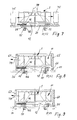
- FIG. 3 shows a second exemplary embodiment with spacer bolts 25 attached to the underside of the shaped piece, by means of which it is possible to also arrange components on the printed circuit board 20 below the fan 1.
- An axial bearing cap 56 serves like the bearing shell 6 in FIG. 1 u. 2 for the axial mounting of the shaft 5.
- a locking ring 57 engages in an annular groove 59 of the shaft 5 and thus secures an unwanted separation of the rotor from the stator.
- FIG. 4 shows a third exemplary embodiment of a fan, which essentially corresponds to that described above, but has its own printed circuit board 30 for the drive electronics of the fan motor.
- This fan is used where there is no drive electronics on a device circuit board.
- This fan together with its circuit board 30 can also be automatically equipped and soldered.
- the attachment takes place via an additional plastic cover 60 fastened by a snap connection, via fastening means 15 or resilient snap hooks 61 or side tabs 81.
- the cover 60 serves as a protective cover and at the same time as a holder for the fan 1, the fitting 12 being fixed to the cover 60 is connected, for example by means of a snap or snap connection.
- the two guide pins 51; 52 which have only a mechanical support function in the exemplary embodiments described above, are used here as connecting pins for the power supply of the fan.
- the one ends 151; 152 with the power supply to the motor 10 and the other ends 153; 154 associated with the power source.
- a stop surface 55 serves as an axial securing device for the rotor of the motor 10.
- FIG. 5 essentially corresponds to the exemplary embodiment shown and described in FIG. 2.
- a ferromagnetic disk 19 for example a steel disk, is applied here on the outer circumferential surface of the bearing support tube 14 at an axial distance from the auxiliary magnetic disk 18.
- a spacer ring 29 is arranged between the disks 18 and 19, which can simply be pressed onto the bearing support tube 14. This version is used when the fan 1 is installed "hanging".
- the outer area of the steel disk 19 protrudes at a short distance in the axial direction into the end area of the rotor magnet 45. This arrangement generates axial magnetic forces on the rotor which prevent the rotor from falling out.
- the noise caused by the rotor of the fan 1 striking the stop surface 55 for example due to high shock loads in motor vehicles
- FIG. 6 shows in principle the use of the fan 1 as a so-called sensor fan in a motor vehicle.
- a sensor 71 openings 72, e.g. in the dashboard, an air stream 79 is sucked out of the interior of the vehicle and, for example, the room temperature is regulated by means of the sensor.
- FIG. 7 shows in principle the use of the fan 1 as a so-called circuit board fan for cooling heat-generating components 75 on a circuit board 20 or the like.
- the very compact fan 1 according to the invention is mounted on the printed circuit board 20 at the point where the air flow 79 can cool the components 75 most effectively.
- Fig. 8 shows an additional air duct housing 65, which is arranged outside around the fan wheel 11 and is attached to the fitting 12 with snap hooks 66.
- An air outlet opening 67 can have different cross-sectional shapes and cross-sectional sizes depending on the intended use and thus specifically blow out the cooling air stream 79.
- FIG. 9 an additional air duct housing 68 is attached to the device circuit board 20.
- the cross section and the size of the air outlet opening 67 are designed such that the cooling air flow 79 runs as optimally as possible and in a predeterminable direction.
- FIG. 10 and FIG. 11 show, in simplified form, the horizontal fastening options of the fan 1 on the one hand directly on the printed circuit board 20 (FIG. 10) and on the other hand at a distance from the printed circuit board 20 (FIG. 11) which is reached by the bolts 25 becomes .
- FIG. 12 An angled holder 69 is shown in FIG. 12, which shows a further possibility of fastening the fan 1.
- the ends 162 of the pins 16 can be designed with little additional cost so that they protrude through the circuit board or mounting plate.
- the elongated ends 162 can thus serve as a mechanical and at the same time electrical connection and fastening.
- the extended ends 162 can also be used as soldering pins which are connected to the circuit board by means of soldering, as described above.
- the fan 1 can be used in devices subject to vibration with an arrangement according to FIG. 13.
- the fan 1 is in its fastening parts 15 in elastic bushings 78; 79 introduced.
- the sockets are simply buttoned into the holes provided.
- the connecting wires 9 of the winding 13 are designed in the manner of a helical spring in order to absorb the vibrations and to prevent the soldered connections from being loosened.
- connecting wires 9 on associated contact points 77 on the printed circuit board 20.
- the embodiment according to FIG. 15 is suitable for a particularly secure fastening of the fan 1.
- the slotted fastening parts 15 are provided with an internal thread. After insertion into the circuit board or the like. Screws 81 are screwed into the internal thread of the parts 15, as a result of which the parts spread out in the end region.
- Providing the drive electronics for the operation of the fan 1 on the device-side circuit board 20 results in a significant cost saving.
- This drive electronics is generally applied to the circuit board 20 by the user.
- the construction of a fan according to the invention is explained in this application using the example of a drive motor with electronic commutation, only one drive winding and an axial air gap, but is not restricted to this motor type.
Abstract
Description
Die Erfindung betrifft einen Lüfter mit einem Lüfterrad, welches auf dem permanentmagnetischen Rotor eines kollektorlosen Gleichstrommotors angeordnet ist.The invention relates to a fan with a fan wheel, which is arranged on the permanent magnetic rotor of a collectorless DC motor.
Ein derartiger Lüfter ist aus dem DE-U-8 702 271 bekannt. Dieser Lüfter weist aber relativ viele Einzelteile und eine zu große Bauhöhe auf.Such a fan is known from DE-U-8 702 271. However, this fan has a relatively large number of individual parts and an excessive height.
Ein Lüfter dieser Art ist auch in der US-A-5 176 509 beschrieben. Dieser Lüfter zeigt zwar einen vereinfachten Aufbau, ist aber ebenfalls in axialer Richtung zu hoch.A fan of this type is also described in US-A-5 176 509. Although this fan has a simplified structure, it is also too high in the axial direction.
Ferner kennt man aus der WO93/19510 einen Lüfter mit einem Lüfterrad, welches auf dem permanentmagnetischen Rotor eines elektronisch kommutierten Kleinmotors angeordnet ist. Zwischen diesem Rotor und der Statorwicklung befindet sich ein Kurzschlußring, der das Anlauf-Drehmoment des Motors nicht verändert, aber es ermöglicht, die Betriebsdrehzahl des Motors auf einen gewünschten Wert zu senken.Also known from WO93 / 19510 is a fan with a fan wheel which is arranged on the permanent magnetic rotor of an electronically commutated small motor. There is a short-circuit ring between this rotor and the stator winding, which does not change the starting torque of the motor, but enables the operating speed of the motor to be reduced to a desired value.
Aus der DE-A-2 718 428 kennt man einen Kompakt-Kleinstlüfter, bei dem zur Erzeugung eines magnetischen Hilfsmoments auf einem Lagertragrohr ein etwa quadratisches Weicheisenstück festgeklebt ist, und zwar innerhalb eines Rotormagnetrings, um in Zusammenwirken mit diesem ein Reluktanzmoment zu erzeugen.From DE-A-2 718 428 a compact mini fan is known in which an approximately square piece of soft iron is glued to a bearing support tube to generate a magnetic auxiliary torque, within a rotor magnet ring, in order to generate a reluctance torque in cooperation therewith.
Zur Kühlung von wärmeerzeugenden Bauteilen auf Platten, insbesondere Leiterplatten, besteht zunehmend der Bedarf, in der Nähe dieser Bauteile für eine wirksame Abfuhr der Wärme einen kompakten Lüfter anzuordnen.To cool heat-generating components on boards, in particular printed circuit boards, there is an increasing need to arrange a compact fan in the vicinity of these components for effective heat dissipation.
Die eingangs genannten und weitere bekannte Lüfter können zwar mit relativ hohem Aufwand auf einer Leiterplatte montiertwerden, lassen sich aber nicht wie sonstige Bauteile (Widerstände, Transistoren, Kondensatoren etc.) unmittelbar auf einer Leiterplatte bestücken und anschließend durch ein Lötbad schicken.The above-mentioned and other known fans can be used with relative can be mounted on a printed circuit board at great expense, but cannot be assembled directly on a printed circuit board like other components (resistors, transistors, capacitors, etc.) and then sent through a solder bath.
Aufgabe der Erfindung ist es, einen Lüfter der vorgenannten Art im Aufbau weiter zu vereinfachen und so zu gestalten, daß der komplett montierte Lüfter wie andere Bauteile unmittelbar auf einer Leiterplatte oder dergleichen bestückt werden kann.The object of the invention is to further simplify the design of a fan of the aforementioned type and to design it in such a way that the completely assembled fan, like other components, can be fitted directly onto a printed circuit board or the like.
Gelöst wird diese Aufgabe durch einen Lüfter mit einem Lüfterrad, welches als Teil des mit einem Rotormagneten versehenen Rotors eines kollektorlosen Gleichstrommotors ausgebildet ist, mit einer Statoranordnung, welche einen Träger für eine Statorwicklung aufweist, welche Statorwicklung mindestens eine Antriebswicklung und eine zur Steuerung der Kommutierung dienende Sensorwicklung aufweist, mit einem am Träger befestigten Lagertragrohr zur Aufnahme einer Lageranordnung für die Welle des Lüfterrades, mit einer auf der Außenseite des Lagertragrohres vorgesehenen magnetischen Anordnung zur Erzeugung eines magnetischen Hilfsmoments im Zusammenwirken mit dem Rotormagneten, mit einem am Träger vorgesehenen ferromagnetischen Element als magnetischer Rückschluß für den Rotormagneten, und mit am Träger vorgesehenen Befestigungsmitteln zur Befestigung des Trägers auf einer Leiterplatte oder dergleichen, und mit am Träger vorgesehenen elektrischen Anschlüssen für die mindestens eine Antriebswicklung und die Sensorwicklung zur elektrischen Verbindung dieser Wicklungen mit auf der Leiterplatte oder dergleichen vorgesehenen Antriebselektronik des Motors.This object is achieved by a fan with a fan wheel, which is designed as part of the rotor of a brushless DC motor provided with a rotor magnet, with a stator arrangement which has a carrier for a stator winding, which stator winding has at least one drive winding and one for controlling the commutation Sensor winding has, with a bearing support tube attached to the carrier for receiving a bearing arrangement for the shaft of the fan wheel, with a magnetic arrangement provided on the outside of the bearing support tube for generating a magnetic auxiliary torque in cooperation with the rotor magnet, with a ferromagnetic element provided on the carrier as a magnetic yoke for the rotor magnet, and with fastening means provided on the carrier for fastening the carrier on a printed circuit board or the like, and with electrical connections provided on the carrier for the at least a drive winding and the sensor winding for the electrical connection of these windings with drive electronics of the motor provided on the printed circuit board or the like.
Der erfindungsgemäße Aufbau ermöglicht es, den fertig montierten Lüfter beispielsweise auf einer Leiterplatte eines Gerätes oder dergleichen aufzubringen, z.B. durch eine Schnapp- oder Steckverbindung, und anschließend mit der bestückten Leiterplatte durch ein Lötbad zu gehen und dort die elektrischen Anschlüsse der Wicklungen mit der Leiterplatte zu verbinden, womit eine weitere Montagevereinfachung erreicht wird.The construction according to the invention makes it possible to apply the fully assembled fan, for example, to a printed circuit board of a device or the like, for example by means of a snap or plug connection, and then to walk through the soldering bath with the printed circuit board and to close the electrical connections of the windings to the printed circuit board connect, which further simplifies assembly.
Die erfindungsgemäße Gestaltung des Statorträgers, der vorzugsweise als Kunststoff-Formstück ausgebildet ist, und die im Formstück enthaltenen elektrischen Anschlüsse (z.B. eingespritzte Anschlußstifte) ermöglichen eine automatisierte Fertigung, d.h. das Wickeln, Anschlagen, Anlöten und Prüfen können auf einem Automaten erfolgen.The inventive design of the stator carrier, which is preferably designed as a plastic molding, and the electrical connections contained in the molding (for example, injected connecting pins) enable automated production, ie the winding, attaching, soldering and testing can be carried out on a machine.
Das Kunststoff-Formstück nach der Erfindung kann ebenfalls vollautomatisch ohne manuelles Einlegen der Anschlußstifte und des Rückschlußelementes gefertigt werden.
Die gedeckelte Ausführung des Radiallüfterrades ermöglicht neben der geringen Bauhöhe eine bessere Führung des Luftstroms.
Der Aufbau des Lüfters gemäß der Erfindung erweitert die Anwendungsund Befestigungsmöglichkeiten.
Weitere Einzelheiten und vorteilhafte Weiterbidungen der Erfindung ergeben sich aus den im folgenden beschriebenen und in der Zeichnung dargestellten Ausführungsbeispielen sowie aus den Unteransprüchen.The plastic molding according to the invention can also be manufactured fully automatically without manually inserting the connecting pins and the yoke element.
The capped design of the radial fan wheel enables not only the low overall height but also better guidance of the air flow.
The construction of the fan according to the invention extends the application and fastening options.
Further details and advantageous developments of the invention result from the exemplary embodiments described below and shown in the drawing and from the subclaims.
Es zeigen
- Fig. 1
- die Unteransicht eines ersten Ausführungsbeispiels eines erfindungsgemäßen Lüfters ;
- Fig. 2
- einen Schnitt entlang der Linie II-II in Fig. 1 ;
- Fig. 3
- ein zweites Ausführungsbeispiel eines erfindungsgemäßen Lüfters im Schnitt ;
- Fig. 4
- ein drittes Ausführungsbeispiel eines erfindungsgemäßen Lüfters im Schnitt ;
- Fig. 5
- ein viertes Ausführungsbeispiel eines erfindungsgemäßen Lüfters im Schnitt;
- Fig. 6 und 7
- Anwendungsbeispiele ;
- Fig. 8 und 9
- Lüfter gemäß der Erfindung mit zusätzlichem Luftführungsgehäuse und
- Fig. 10 bis 15
- Befestigungsbeispiele für die erfindungsgemäßen Lüfter .
- Fig. 1
- the bottom view of a first embodiment of a fan according to the invention;
- Fig. 2
- a section along the line II-II in Fig. 1;
- Fig. 3
- a second embodiment of a fan according to the invention in section;
- Fig. 4
- a third embodiment of a fan according to the invention in section;
- Fig. 5
- a fourth embodiment of a fan according to the invention in section;
- 6 and 7
- Application examples;
- 8 and 9
- Fan according to the invention with an additional air duct housing and
- 10 to 15
- Mounting examples for the fan according to the invention.
In Fig. 1 ist ein Lüfter 1 in einer Ansicht von unten dargestellt. Diese Ansicht zeigt einen Träger 12, der als Kunststoff-Formstück ausgebildet ist. Elektrische Anschlüsse 16 , beispielsweise als Anschlußstifte ausgebildet , und Führungsstifte 51;52 sind im Formstück 12 angeordnet, vorzugsweise eingespritzt. Diese eingespritzten oder eingelegten Anschlußstifte 16 bestehen aus elektrisch leiffähigem Material, beispielsweise aus Metall. Das eine Ende 161 der Stifte 16 ist leitend jeweils mit einem Ende der Wicklungsdrähte 9 verbunden und das andere Ende 162 der Stifte 16 ragt aus dem Träger 12 heraus. Diese Enden 162 werden in dafür vorgesehene Öffnungen oder Vertiefungen einer Leiterplatte 20 (strichpunktiert gezeichnet) gesteckt und verlötet , d. h. kontaktierend mit der Antriebselektronik für den Motor 10 des Lüfters 1 in Verbindung gebracht. Die Anschlußstifte 16 sind vorzugsweise rechtwinklig ausgebildet , wobei das eine Ende 161 in der Ebene des als im wesentlichen als ebenes Teil ausgebildeten Trägers 12 angeordnet ist und das Ende 162 im wesentlichen rechtwinklig aus dem Träger 12 herausragt. Ebenso sind die Führungsstifte 51; 52 vorzugsweise auch als rechtwinklige Stifte aus einem elektrisch leitfähigen Material ausgebildet , deren eine Enden 151 ; 152 in der Ebene des Trägers 12 liegen und deren andere Enden 153 ; 154 im wesentlichen in gleicher Länge und parallel zu den anderen Enden 162 der Anschlußstifte 16 aus dem Träger 12 herausragen.
Ein Rückschlußelement 17 für einen Rotormagneten 45 , im Ausführungsbeispiel eine ferromagnetische Blechscheibe in Form eines Kreisrings , ist ebenfalls im Formstück 12 mit eingespritzt. Befestigungsmittel 15, beispielsweise als geschlitzte Schnappbolzen ausgeführt , sind an der Unterseite des Formstücks angespritzt. Die Befestigungsmittel dienen als Montagehilfe bzw. zur Befestigung des Lüfters 1 an einer Leiterplatte 20 , die in Fig. 2 strichpunktiert angedeutet ist. An der Unterseite des Formstücks 12 sind Abstandsbolzen 15 angebracht , vorzugsweise auch angespritzt , die zur Einhaltung eines Abstands zwischen der Unterseite des Formstücks 12 und der Platte 20 dienen oder die als Paß- oder Führungsbolzen genutzt werden können.
Die oben beschriebene erfindungsgemäße Ausgestaltung des Stators , insbesondere des Statorträgers 12 , ermöglicht eine weitgehend automatisierte Fertigung , d.h. das Wickeln , Anschlagen und Anlegen der Wicklungsenden an die Stifte 16 , Anlöten und Prüfen können auf einem Automaten erfolgen.In Fig. 1, a
A
The above-described configuration of the stator, in particular of the
Fig. 2 zeigt im Schnitt entlang der Linie II-II in Fig. 1 Einzelheiten des Ausführungsbeispiels gemäß Fig. 1. Auf einem Spulenkörper 121 , der in diesem Ausführungsbeispiel auch Teil des Trägers 12 ist , ist eine Statorwicklung 13 aufgebracht, die eine Antriebs - und eine Sensorwicklung aufweist.
Ein Lüfterrad 11 , in diesem Fall als sog. gedeckeltes Radiallüfterrad ausgeführt, enthält eine Welle 5 , die als Rotorwelle dient. Die Welle 5 ist in einer Lageranordnung 34 radial gelagert. Die Lageranordnung 34, beispielsweise ein Sinterdoppellager, ist in einem Lagertragrohr 14 befestigt. Die Lageranordnung 34 kann je nach Verwendung auch als Wälzlagerung ausgeführt sein .Das Lagertragrohr 14 ist vorzugsweise auch Teil des gespritzten Formstücks 12. Ein oberer in axialer Richtung verlängerter und im Außendurchmesser verkleinerter Rand 8 des Lagertragrohres 14 dient in Verbindung mit einem im Außendurchmesser verkleinerten Bereich des Sinterlagers 34 zur axialen Sicherung des Lagers 34 Das Sinterlager 34 läßt sich auch durch Kleben , Verstemmen u. ä. befestigen. Im Bereich des oberen Randes 8 ist eine magnetische Hilfsanordnung 18 (ferromagnetische oder permanentmagnetische Anordnung) befestigt. Diese Hilfsanordnung 18 kann zur weiteren Kostensenkung als aus gummimagnetischem Material gestanzte Scheibe ausgeführt sein. Eine in das Lagertragrohr 14 eingelegte Lagerschale 6 bildet die axiale Lagerung der Welle 5. Die Anordnung der Lagerschale 6 bestimmt die Größe des im wesentlichen ebenen Luftspaltes 7 zwischen einem Rotormagneten 45 und einer Statorwicklung 13. Dieser einfache und äußerst kostengünstige kollektorlose Gleichstrommotor 10 weist, wie bereits aus der DE- GM 87 02 271 bekannt, nur eine Statorwicklung auf, die aus einer Antriebswicklung und einer Sensorwicklung besteht und vorzugsweise bifilar gewickelt ist. Zur Vermeidung von Längen wird bezüglich der Form der Wicklung und der Schaltung auf den Inhalt der DE-GM 87 02 271 Bezug genommen.
Das Lüfterrad 11 enthält im wesentlichen radial verlaufende Schaufeln 21 , die zwischen einem ersten Führungsglied 41 und einem zweiten Führungsglied 42 angeordnet sind. Das erste Führungsglied 41 weist eine zentrale Lufteintrittsöffnung 43 auf und ist im wesentlichen eben ausgebildet. Das erste und das zweite Luftführungsglied 41; 42 bilden im axialen Querschnitt gesehen in diesem Ausführungsbeispiel einen sich in Richtung nach außen erweiternden Luftaustrittsquerschnitt . Für andere Anwendungen können auch ein sich verengender Querschnitt und auch verschiedene Querschnittsformen konzipiert werden.
Im Bereich der Lufteintrittsöffnung 43 befindet sich ein Abschnitt 58 , in welchem die Welle 5 des Lüfterrades 11 befestigt ist. Im zweiten Luftführungsglied 42 ist eine ferromagnetische Rückschlußscheibe 44 befestigt, auf der der Rotormagnet 45 für den motorischen Antrieb des Lüfterrades 11 angeordnet ist. Es kann auch ein polorientierter Magnet ohne Rückschlußscheibe eingesetzt werden.
Die elektrischen Bauelemente (Transistoren , Widerstände usw.) für den Motor 1 befinden sich auf der Leiterplatte 20.2 shows in section along the line II-II in FIG. 1 details of the exemplary embodiment according to FIG. 1. On a coil former 121, which in this exemplary embodiment is also part of the
A
The
In the area of the air inlet opening 43 there is a
The electrical components (transistors, resistors, etc.) for the
Fig. 3 zeigt ein zweites Ausführungsbeispiel mit an der Unterseite des Formstücks angebrachten Abstandsbolzen 25 , durch die ermöglicht wird , auch unterhalb des Lüfters 1 auf der Leiterplatte 20 Bauteile anzuordnen. Eine Axiallagerkappe 56 dient wie die Lagerschale 6 in Fig. 1 u. 2 zur axialen Lagerung der Welle 5.
Ein Sicherungsring 57 greift in eine Ringnut 59 der Welle 5 und sichert so ein ungewolltes Trennen des Rotors vom Stator.FIG. 3 shows a second exemplary embodiment with
A locking
Fig. 4 zeigt ein drittes Ausführungsbeispiel eines Lüfters, der im wesentlichen den oben beschriebenen entspricht, allerdings eine eigene Leiterplatte 30 für die Antriebselektronik des Lüftermotors aufweist. Dieser Lüfter wird dort eingesetzt, wo eine Antriebselektronik auf einer Geräte-Leiterplatte nicht vorgesehen ist. Auch dieser Lüfter mitsamt seiner Leiterplatte 30 kann automatisch bestückt und angelötet werden. Die Befestigung geschieht über eine zusätzliche, durch eine Schnappverbindung befestigte Kunststoffabdeckung 60 , über Befestigungsmittel 15 oder federnde Schnapphaken 61 oder seitliche Laschen 81. Die Abdeckung 60 dient als Schutzabdeckung und gleichzeitig als Halterung für den Lüfter 1 , wobei das Formstück 12 fest mit der Abdeckung 60 verbunden ist, z.B mittels einer Schnapp- oder Rastverbindung. Die beiden Führungsstifte 51; 52 , die bei den oben beschriebenen Ausführungsbeispielen nur eine mechanische Stützfunktion haben , werden hier als Anschlußstifte für die Stromversorgung des Lüfters benutzt. Dabei werden die einen Enden 151 ; 152 mit der Stromzuführung des Motors 10 und die anderen Enden 153 ; 154 mit der Stromquelle in Verbindung gebracht. Eine Anschlagfläche 55 dient als Axialsicherung für den Rotor des Motors 10 .4 shows a third exemplary embodiment of a fan, which essentially corresponds to that described above, but has its own printed
Fig. 5 entspricht im wesentlichen dem in Fig. 2 dargestellten und beschriebenen Ausführungsbeispiel . Zusätzlich ist hier auf der äußeren Umfangsfläche des Lagertragrohrs 14 in axialem Abstand zur Hilfsmagnetscheibe 18 eine ferromagnetische Scheibe 19, beispielsweise eine Stahlscheibe, aufgebracht. Zur sicheren Befestigung ist zwischen den Scheiben 18 und 19 ein Abstandsring 29 angeordnet , der einfach auf das Lagertragrohr 14 aufgepreßt sein kann. Diese Ausführung kommt zur Anwendung,wenn der Lüfter 1 "hängend" eingebaut wird. Dabei ragt der Außenbereich der Stahlscheibe 19 mit geringem Abstand in axialer Richtung in den stirnseitigen Bereich des Rotormagneten 45. Durch diese Anordnung werden axiale Magnetkräfte auf den Rotor erzeugt, die das Herausfallen des Rotors verhindern.
Ebenso wird das Geräusch , das durch ein Anschlagen des Rotors des Lüfters 1 an die Anschlagfläche 55 verursacht wird (z.B. aufgrund hoher Stoßbelastungen in Kraftfahrzeugen) , verhindert.FIG. 5 essentially corresponds to the exemplary embodiment shown and described in FIG. 2. In addition, a
Likewise, the noise caused by the rotor of the
Fig. 6 zeigt prinzipiell die Verwendung des Lüfters 1 als sog. Sensorlüfter in einem Kraftfahrzeug. Über einen Sensor 71 wird durch Öffnungen 72 , z.B. im Armaturenbrett, ein Luftstrom 79 aus dem Innenraum des Fahrzeugs angesaugt und mittels des Sensors beispielsweise die Raumtemperatur geregelt .6 shows in principle the use of the
Fig. 7 zeigt im Prinzip die Verwendung des Lüfters 1 als sog. Leiterplattenlüfter zur Kühlung von wärmeerzeugenden Bauelementen 75 auf einer Leiterplatte 20 oder dergleichen. Der sehr kompakte erfindungsgemäße Lüfter 1 wird auf der Leiterplatte 20 an der Stelle angebracht , wo der Luftstrom 79 die Bauelemente 75 am wirksamstem kühlen kann .7 shows in principle the use of the
Fig. 8 zeigt ein zusätzliches Luftführungs-Gehäuse 65 , das außerhalb um das Lüfterrad 11 herum angeordnet und am Formstück 12 mit Schnapphaken 66 befestigt ist. Eine Luftaustrittsöffnung 67 kann dabei je nach Verwendungszweck verschiedene Querschnittsformen und Querschnittsgrößen aufweisen und so den kühlenden Luftstrom 79 gezielt ausblasen .Fig. 8 shows an additional
In Fig. 9 ist ein zusätzliches Luftführungs-Gehäuse 68 auf der Geräte-Leiterplatte 20 angebracht. In beiden Fällen (Fig.8 u. 9) wird der Querschnitt und die Größe der Luftaustrittsöffnung 67 so ausgelegt, daß der kühlende Luftstrom 79 möglichst optimal und in einer vorgebbaren Richtung verläuft.In Fig. 9, an additional
Fig. 10 und Fig. 11 zeigen , vereinfacht dargestellt , die waagerechten Befestigungsmöglichkeiten des Lüfters 1 zum einen direkt auf der Leiterplatte 20 (Fig. 10) und zum andern im Abstand zur Leiterplatte 20 (Fig. 11), der durch die Bolzen 25 erreicht wird .10 and FIG. 11 show, in simplified form, the horizontal fastening options of the
In Fig. 12 ist ein abgewinkelter Halter 69 dargestellt, der eine weitere Möglichkeit der Befestigung des Lüfters 1 zeigt. Die Enden 162 der Stifte 16 können mit geringen Mehrkosten so ausgeführt werden , daß sie durch die Leiter- oder Befestigungsplatte hindurchragen. Die verlängerten Enden 162 können so als mechanische und gleichzeitig elektrische Verbindung und Befestigung dienen. Die verlängerten Enden 162 können aber auch als Lötstifte genutzt werden , die wie oben beschrieben mit der Leiterplatte mittels Löten verbunden werden .An
Der Einsatz des Lüfters 1 kann in schwingungsbelasteten Geräten mit einer Anordnung gemäß Fig. 13 erfolgen. Der Lüfter 1 wird über seine Befestigungsteile 15 in elastische Buchsen 78 ; 79 eingebracht. Die Buchsen werden einfach in dafür vorgesehene Bohrungen eingeknöpft. Die Anschlußdrähte 9 der Wicklung 13 sind in der Art einer Schraubenfeder gestaltet, um auch hier die Schwingungen aufzufangen und eine Lösung der Lötverbindungen zu verhindern.The
In Fig. 14 ist eine besonders einfache Art der Kontaktierung der Anschlußdrähte 9 auf dazugehörigen Kontaktstellen 77 auf der Leiterplatte 20. Die als Druckfedern ausgebildeten Enden der Anschlußdrähte 9 kontaktieren unmittelbar die Kontakte 77 .14 shows a particularly simple way of contacting the connecting
Für eine besonders sichere Befestigung des Lüfters 1 ist die Ausführung gemäß Fig. 15 geeignet. Die geschlitzten Befestigungsteile 15 sind mit einem Innengewinde versehen. Nach dem Einstecken in die Leiterplatte oder dgl. werden Schrauben 81 in das Innengewinde der Teile 15 geschraubt , wodurch sich die Teile im Endbereich aufspreizen.The embodiment according to FIG. 15 is suitable for a particularly secure fastening of the
Eine wesentliche Kosteneinsparung erbringt das Vorsehen der Antriebselektronik für den Betrieb des Lüfters 1 auf der geräteseitigen Leiterplatte 20. Diese Antriebselektronik wird in der Regel vom Anwender auf der Leiterplatte 20 aufgebracht.
Der erfindungsgemäße Aufbau eines Lüfters ist in dieser Anmeldung am Beispiel eines Antriebsmotors mit elektronischer Kommutierung , nur einer Antriebswicklung und axialem Luftspalt erläutert , nicht aber auf diesen Motortyp eingeschränkt.Providing the drive electronics for the operation of the
The construction of a fan according to the invention is explained in this application using the example of a drive motor with electronic commutation, only one drive winding and an axial air gap, but is not restricted to this motor type.
Selbstverständlich sind im Rahmen der vorliegenden Erfindung noch zahlreiche weitere Abwandlungen und Modifikationen möglich , wie sich das für den Fachmann ohne weiteres ergibt.Of course, numerous other modifications and modifications are possible within the scope of the present invention, as is readily apparent to those skilled in the art.
Claims (17)
- Fan with a fan wheel (11) which is embodied as part of the rotor provided with a rotor magnet (45) of a commutatorless direct current motor (10), with a stator arrangement which exhibits a carrier (12) for a stator winding (13),which stator winding exhibits at least one driving winding and a sensor winding serving for control of commutation,with a bearing supporting tube (14) disposed on the carrier (12) for accommodation of a bearing arrangement (34) for the shaft (5) of the fan wheel (11),with a magnetic arrangement (18) provided on the outside of the bearing supporting tube (14) for generation of a magnetic auxiliary moment in collaboration with the rotor magnet (45),with a ferromagnetic element (17) provided on the carrier (12) as magnetic return for the rotor magnet (45),with fixing means (15) provided on the carrier (12) for fixture of the carrier (12) on a circuit board (20) or the like,and with electrical connections (16) provided on the carrier (12) for the at least one driving winding and the sensor winding for electrical connection of these windings with motor driving electronics provided on the circuit board (20) or the like.
- Fan according to claim 1, in which the carrier (12) is embodied as a one-piece plastic moulding which exhibits a coil former (121) on which is located the stator winding (13) which exhibits the driving and sensor windings,with connectors (16) embedded in the carrier (12) and embodied as metal pins, whereby at one end (161) of the pins the respective winding end of the winding wires (9) makes contact and the other end (162) of the pins projects out of the carrier (12) for fitment of the carrier (12) on the circuit board (20) and for electrical connection with the latter,with a bearing supporting tube (14) disposed on the carrier (12) inside the coil former (121) and in which a bearing arrangement (34) is fixed for mounting of the shaft (5),with fixing means (15) fitted to the carrier (12) for its fixture on the circuit board (20),and with spacer pins (25) fitted to the carrier (12).
- Fan according to claim 2, in which embedded angled connecting pins (16) made of electrically conducting material and embedded angled guiding pins (51, 52) are provided, whereby one end (151, 152) of the pins is disposed essentially in the plane of the carrier (12), whereas the other end (153, 154) projects out of the moulding (12) essentially with the same length and parallel to the other ends (162) of the connecting pins (16).
- Fan according to claim 2, in which the carrier (12) is embodied as an essentially flat moulding in which the electrical connections (16) for the windings (13) extend roughly in the plane of the moulding and outside the space required for winding the coil former (121).
- Fan according to one or more of the preceding claims, in which a permanently magnetic part (18), in particular a disc of rubber magnetic material, is provided on the outside of the bearing supporting tube (14), which part (18) generates an auxiliary moment depending on the rotational position in collaboration with the rotor magnet (45).
- Fan according to one or more of the preceding claims, in which a preferably plate-shaped ferromagnetic part (17) is disposed in the moulding (12) in the area outside the bearing supporting tube (14).
- Fan according to one or more of the preceding claims, in which a bearing shell (16) for axial mounting of the shaft (5) is fitted in the bearing supporting tube (14) in the area of one end of the bearing supporting tube (14).
- Fan according to one or more of the preceding claims, with a fan wheel with blades (21) which run essentially radially and are disposed between a first air guiding element (41) and a second air guiding element (42), of which the first air guiding element (41) exhibits a central air inlet opening (43) and the second air guiding element (42), together with the first air guiding element (41), viewed in axial section, forms an air passage cross-section which widens in the outward direction and in the area of the air inlet opening (43) exhibits a portion (58) in which the shaft (5) of the fan wheel (11) is fixed, further with a ferromagnetic return disc (44) fixed in the second air guiding element (42), and
with at least one permanent magnet (45) fixed in the second air guiding element (42) and disposed on the return disc (44) for the motorised drive of the fan wheel (11). - Fan according to claim 8, in which the second air guiding element (42) extends in the axial direction beyond the end of the permanent magnetic (45) remote from the fan wheel (11).
- Fan according to claim 8 or 9, in which the second air guiding element (42) is embodied with roughly the shape of a truncated cone at least in areas.
- Fan according to one of claims 8 to 10, in which the first air guiding element (41) is embodied essentially flat.
- Fan according to one or more of claims 8 to 11, in which the portion of the second air guiding element (42) in which the shaft (5) is fixed projects through the air inlet opening (43).
- Fan according to one or more of claims 8 to 12, in which the second air guiding element (42) is provided with a collar-like projection (46) which is disposed around the outside circumference of the ring-shaped permanent magnet (45).
- Fan according to one or more of claims 8 to 13, in which the first and the second air guiding elements (41, 42) exhibit essentially the same diameter.
- Fan according to one or more of claims 8 to 14, in which the ferromagnetic return disc (44) is embodied as a ring-shaped disc and is mounted by its inner edge in a portion of the second air guiding element (42).
- Fan according to one or more of the preceding claims, with a circuit board (30) which is fitted directly to the carrier (12) and carries circuit elements for the commutatorless direct current motor, and with a cover (60) which exhibits sprung snap hooks (61).
- Fan according to one or more of the preceding claims, with a ferromagnetic disc (19) which is disposed on the outer circumferential surface of the bearing supporting tube (14) and serves for generation of an essentially axial magnetic pull on the rotor magnet (45), and with a spacer ring (29) which is fixed between the magnetic disc (18) and the disc (19) on the bearing supporting tube (14), the outer area of the disc (19) projecting into the area of the rotor magnet (45).
Priority Applications (1)
| Application Number | Priority Date | Filing Date | Title |
|---|---|---|---|
| DE29521591U DE29521591U1 (en) | 1994-02-05 | 1995-02-02 | Fan with a fan wheel |
Applications Claiming Priority (2)
| Application Number | Priority Date | Filing Date | Title |
|---|---|---|---|
| DE9401909U | 1994-02-05 | ||
| DE9401909 | 1994-02-05 |
Publications (2)
| Publication Number | Publication Date |
|---|---|
| EP0666424A1 EP0666424A1 (en) | 1995-08-09 |
| EP0666424B1 true EP0666424B1 (en) | 1997-10-15 |
Family
ID=6904182
Family Applications (1)
| Application Number | Title | Priority Date | Filing Date |
|---|---|---|---|
| EP95101408A Expired - Lifetime EP0666424B1 (en) | 1994-02-05 | 1995-02-02 | Fan with rotor, in particular a radial fan rotor |
Country Status (3)
| Country | Link |
|---|---|
| EP (1) | EP0666424B1 (en) |
| AT (1) | ATE159326T1 (en) |
| DE (3) | DE59500779D1 (en) |
Cited By (2)
| Publication number | Priority date | Publication date | Assignee | Title |
|---|---|---|---|---|
| US6232687B1 (en) | 1999-03-25 | 2001-05-15 | General Electric Company | Electric motor having snap connection assembly |
| US8105011B2 (en) | 2004-10-09 | 2012-01-31 | Ebm-Papst St. Georgen Gmbh & Co. Kg | Fan comprising a fan wheel |
Families Citing this family (22)
| Publication number | Priority date | Publication date | Assignee | Title |
|---|---|---|---|---|
| JP3052304B2 (en) * | 1995-11-17 | 2000-06-12 | 日本精機株式会社 | Stepping motor |
| DE29718082U1 (en) * | 1997-10-11 | 1999-02-11 | Papst Motoren Gmbh & Co Kg | Small fan unit, especially for use as a circuit board fan |
| IT245852Y1 (en) * | 1998-06-12 | 2002-03-26 | Bitron Spa | FAN IN MOTOR-FAN PLASTIC MATERIAL FOR VEHICLE CABINET |
| DE19941438A1 (en) * | 1998-08-31 | 2000-03-09 | Wiedenmann Gmbh | Appliance for gathering grass/sweepings/leaves, etc., has a fan blower within a housing rotating at lower speeds to give lower noise levels in a smaller space without loss of suction/blowing power |
| FR2786336B1 (en) * | 1998-11-20 | 2004-12-03 | Matsushita Electric Ind Co Ltd | BRUSHLESS MOTOR AND ASSEMBLY METHOD THEREOF |
| EP1142082B1 (en) * | 1998-12-23 | 2005-02-23 | Siemens Aktiengesellschaft | Electric motor to be attached to a printed board |
| EP1104950B1 (en) | 1999-11-27 | 2004-12-08 | ebm-papst St. Georgen GmbH & Co. KG | Electronically commutated D.C. motor |
| EP1107441A3 (en) | 1999-12-01 | 2002-09-25 | Papst-Motoren GmbH & Co. KG | Electrically commutated DC-motor |
| DE50015828D1 (en) | 1999-12-08 | 2010-02-04 | Ebm Papst St Georgen Gmbh & Co | Electronically commutated DC motor |
| DE10056773B4 (en) * | 2000-11-16 | 2006-01-12 | AEG Hausgeräte GmbH | radial fans |
| DE10101348A1 (en) * | 2001-01-13 | 2002-08-01 | Bosch Gmbh Robert | Electrically powered cooling fan has conductor projecting from base with ends that are soldered onto circuit board |
| ES2236564T3 (en) | 2001-08-10 | 2005-07-16 | EBM-PAPST ST. GEORGEN GMBH & CO. KG | PROCEDURE FOR CONTROLLING THE SWITCHING OF AN ELECTRONIC SWITCHED ENGINE, AND AN ELECTRONIC SWITCHED ENGINE TO CARRY OUT A PROCEDURE OF THIS TYPE. |
| DE10245971A1 (en) | 2002-09-30 | 2004-04-01 | Ebm Werke Gmbh & Co. Kg | Electric motor with screwless plug-in assembly |
| US7841541B2 (en) | 2003-11-12 | 2010-11-30 | Ebm-Papst St. Georgen Gmbh & Co. Kg | Fan having a sensor |
| JP3809438B2 (en) * | 2003-11-28 | 2006-08-16 | 日本サーボ株式会社 | Centrifugal blower |
| WO2006042635A1 (en) | 2004-10-19 | 2006-04-27 | Ebm-Papst St. Georgen Gmbh & Co. Kg | Assembly used for cooling a circuit board or similar |
| EP1657448A1 (en) * | 2004-10-28 | 2006-05-17 | Asmo Co., Ltd. | Fan |
| DE102007044176A1 (en) * | 2007-09-15 | 2009-03-19 | Gea Air Treatment Gmbh | Drum fan with direct drive |
| TWI349071B (en) * | 2008-02-01 | 2011-09-21 | Delta Electronics Inc | Fan |
| DE102013014128A1 (en) * | 2013-08-23 | 2015-02-26 | Nicotra Gebhardt GmbH | centrifugal fan |
| US10544789B2 (en) * | 2013-10-10 | 2020-01-28 | Regal Beloit America, Inc. | Axial flux electrical motor and fan assembly and methods of assembling the same |
| TWI583870B (en) * | 2015-08-25 | 2017-05-21 | 建準電機工業股份有限公司 | Cooling fan with a coil substrate |
Family Cites Families (7)
| Publication number | Priority date | Publication date | Assignee | Title |
|---|---|---|---|---|
| CH612736A5 (en) * | 1976-04-27 | 1979-08-15 | Papst Motoren Kg | |
| DE8702271U1 (en) * | 1987-02-14 | 1987-06-04 | Papst-Motoren Gmbh & Co Kg, 7742 St Georgen, De | |
| US4866324A (en) * | 1987-04-28 | 1989-09-12 | Canon Kabushiki Kaisha | Brushless motor |
| US4885488A (en) * | 1988-05-23 | 1989-12-05 | Texas Instruments Incorporated | Miniaturized fan for printed circuit boards |
| DE3933868B4 (en) * | 1989-10-11 | 2004-07-01 | Robert Bosch Gmbh | Blower with an electronically commutated drive motor |
| DE9012087U1 (en) * | 1990-08-22 | 1992-01-02 | Papst-Motoren Gmbh & Co Kg, 7742 St Georgen, De | |
| DE4208471A1 (en) * | 1992-03-17 | 1993-09-23 | Bosch Gmbh Robert | ELECTRICALLY COMMUTED SMALL MOTOR |
-
1995
- 1995-02-02 AT AT95101408T patent/ATE159326T1/en active
- 1995-02-02 DE DE59500779T patent/DE59500779D1/en not_active Expired - Lifetime
- 1995-02-02 EP EP95101408A patent/EP0666424B1/en not_active Expired - Lifetime
- 1995-02-03 DE DE29501695U patent/DE29501695U1/en not_active Expired - Lifetime
- 1995-02-03 DE DE19503521A patent/DE19503521B4/en not_active Expired - Fee Related
Cited By (2)
| Publication number | Priority date | Publication date | Assignee | Title |
|---|---|---|---|---|
| US6232687B1 (en) | 1999-03-25 | 2001-05-15 | General Electric Company | Electric motor having snap connection assembly |
| US8105011B2 (en) | 2004-10-09 | 2012-01-31 | Ebm-Papst St. Georgen Gmbh & Co. Kg | Fan comprising a fan wheel |
Also Published As
| Publication number | Publication date |
|---|---|
| EP0666424A1 (en) | 1995-08-09 |
| DE19503521A1 (en) | 1995-08-10 |
| DE29501695U1 (en) | 1995-06-08 |
| DE19503521B4 (en) | 2008-09-25 |
| ATE159326T1 (en) | 1997-11-15 |
| DE59500779D1 (en) | 1997-11-20 |
Similar Documents
| Publication | Publication Date | Title |
|---|---|---|
| EP0666424B1 (en) | Fan with rotor, in particular a radial fan rotor | |
| EP1689065B1 (en) | Stator for an electric motor and its manufacturing process | |
| EP1422809B1 (en) | Electric motor for a pump drive | |
| EP0993696B1 (en) | Drive, in particular for adjusting a vehicle sliding roof | |
| EP2118493B1 (en) | Fan having a sensor | |
| EP1042854B1 (en) | Commutator-small power motor | |
| CH654455A5 (en) | BRUSHLESS DC MOTOR ARRANGEMENT, ESPECIALLY FOR MAGNETIC DISC DRIVES. | |
| DE3842588A1 (en) | COLLECTORLESS OUTDOOR ROTOR MOTOR WITH SEMICONDUCTOR COOLING ARRANGEMENT | |
| WO1998039836A1 (en) | Electronically switched d.c. motor | |
| DE102016213110A1 (en) | Electric machine | |
| WO2013143711A2 (en) | Electric motor | |
| EP0769840A1 (en) | Brushless electric motor | |
| DE4418000C2 (en) | Electronically controlled electric motor, in particular with a fan wheel for sucking in cooling air for motor vehicles | |
| WO2015197574A1 (en) | Electric machine | |
| DE19812729A1 (en) | Electric motor, in particular with a fan wheel to form an axial or radial fan | |
| DE3820857A1 (en) | FAN DRIVEN BY AN ELECTRIC MOTOR | |
| DE10131761A1 (en) | Electrical machine | |
| DE10205402A1 (en) | electric motor | |
| DE112017001793T5 (en) | engine | |
| EP1026507B1 (en) | Electric motor with rpm-monitor | |
| WO2006117265A1 (en) | Connecting device | |
| WO2010105867A2 (en) | Electric drive engine, especially for a unit in a motor vehicle | |
| DE10133767A1 (en) | Commutator motor with a cylindrical motor housing | |
| DE2230527A1 (en) | FAN WITH AN ELECTRIC MOTOR AND A FAN WHEEL DRIVEN BY THIS | |
| DE102015211800A1 (en) | Electric machine |
Legal Events
| Date | Code | Title | Description |
|---|---|---|---|
| PUAI | Public reference made under article 153(3) epc to a published international application that has entered the european phase |
Free format text: ORIGINAL CODE: 0009012 |
|
| AK | Designated contracting states |
Kind code of ref document: A1 Designated state(s): AT CH DE FR GB IT LI |
|
| 17P | Request for examination filed |
Effective date: 19950914 |
|
| 17Q | First examination report despatched |
Effective date: 19960920 |
|
| GRAG | Despatch of communication of intention to grant |
Free format text: ORIGINAL CODE: EPIDOS AGRA |
|
| GRAG | Despatch of communication of intention to grant |
Free format text: ORIGINAL CODE: EPIDOS AGRA |
|
| GRAH | Despatch of communication of intention to grant a patent |
Free format text: ORIGINAL CODE: EPIDOS IGRA |
|
| GRAH | Despatch of communication of intention to grant a patent |
Free format text: ORIGINAL CODE: EPIDOS IGRA |
|
| GRAA | (expected) grant |
Free format text: ORIGINAL CODE: 0009210 |
|
| AK | Designated contracting states |
Kind code of ref document: B1 Designated state(s): AT CH DE FR GB IT LI |
|
| ITF | It: translation for a ep patent filed |
Owner name: DE DOMINICIS & MAYER S.R.L. |
|
| REF | Corresponds to: |
Ref document number: 159326 Country of ref document: AT Date of ref document: 19971115 Kind code of ref document: T |
|
| REG | Reference to a national code |
Ref country code: CH Ref legal event code: EP |
|
| REF | Corresponds to: |
Ref document number: 59500779 Country of ref document: DE Date of ref document: 19971120 |
|
| GBT | Gb: translation of ep patent filed (gb section 77(6)(a)/1977) |
Effective date: 19971113 |
|
| ET | Fr: translation filed | ||
| PLBI | Opposition filed |
Free format text: ORIGINAL CODE: 0009260 |
|
| PLBF | Reply of patent proprietor to notice(s) of opposition |
Free format text: ORIGINAL CODE: EPIDOS OBSO |
|
| 26 | Opposition filed |
Opponent name: PIERBURG AG Effective date: 19980713 |
|
| PLBF | Reply of patent proprietor to notice(s) of opposition |
Free format text: ORIGINAL CODE: EPIDOS OBSO |
|
| PLBO | Opposition rejected |
Free format text: ORIGINAL CODE: EPIDOS REJO |
|
| APAC | Appeal dossier modified |
Free format text: ORIGINAL CODE: EPIDOS NOAPO |
|
| APAE | Appeal reference modified |
Free format text: ORIGINAL CODE: EPIDOS REFNO |
|
| APAC | Appeal dossier modified |
Free format text: ORIGINAL CODE: EPIDOS NOAPO |
|
| REG | Reference to a national code |
Ref country code: GB Ref legal event code: IF02 |
|
| REG | Reference to a national code |
Ref country code: CH Ref legal event code: PFA Owner name: EBM-PAPST ST. GEORGEN GMBH & CO. KG Free format text: PAPST-MOTOREN GMBH & CO. KG#POSTFACH 1435#78106 ST GEORGEN (DE) -TRANSFER TO- EBM-PAPST ST. GEORGEN GMBH & CO. KG#HERMANN-PAPST-STRASSE 1#78112 ST. GEORGEN (DE) |
|
| RAP2 | Party data changed (patent owner data changed or rights of a patent transferred) |
Owner name: EBM-PAPST ST. GEORGEN GMBH & CO. KG |
|
| APBU | Appeal procedure closed |
Free format text: ORIGINAL CODE: EPIDOSNNOA9O |
|
| PLBN | Opposition rejected |
Free format text: ORIGINAL CODE: 0009273 |
|
| STAA | Information on the status of an ep patent application or granted ep patent |
Free format text: STATUS: OPPOSITION REJECTED |
|
| 27O | Opposition rejected |
Effective date: 20000523 |
|
| APAH | Appeal reference modified |
Free format text: ORIGINAL CODE: EPIDOSCREFNO |
|
| PGFP | Annual fee paid to national office [announced via postgrant information from national office to epo] |
Ref country code: IT Payment date: 20111026 Year of fee payment: 18 |
|
| PGFP | Annual fee paid to national office [announced via postgrant information from national office to epo] |
Ref country code: GB Payment date: 20121217 Year of fee payment: 19 |
|
| PGFP | Annual fee paid to national office [announced via postgrant information from national office to epo] |
Ref country code: FR Payment date: 20130125 Year of fee payment: 19 Ref country code: DE Payment date: 20130201 Year of fee payment: 19 Ref country code: CH Payment date: 20130110 Year of fee payment: 19 |
|
| PGFP | Annual fee paid to national office [announced via postgrant information from national office to epo] |
Ref country code: AT Payment date: 20130118 Year of fee payment: 19 |
|
| REG | Reference to a national code |
Ref country code: DE Ref legal event code: R119 Ref document number: 59500779 Country of ref document: DE |
|
| REG | Reference to a national code |
Ref country code: CH Ref legal event code: PL |
|
| REG | Reference to a national code |
Ref country code: AT Ref legal event code: MM01 Ref document number: 159326 Country of ref document: AT Kind code of ref document: T Effective date: 20140202 |
|
| GBPC | Gb: european patent ceased through non-payment of renewal fee |
Effective date: 20140202 |
|
| PG25 | Lapsed in a contracting state [announced via postgrant information from national office to epo] |
Ref country code: CH Free format text: LAPSE BECAUSE OF NON-PAYMENT OF DUE FEES Effective date: 20140228 Ref country code: LI Free format text: LAPSE BECAUSE OF NON-PAYMENT OF DUE FEES Effective date: 20140228 |
|
| REG | Reference to a national code |
Ref country code: FR Ref legal event code: ST Effective date: 20141031 |
|
| PG25 | Lapsed in a contracting state [announced via postgrant information from national office to epo] |
Ref country code: AT Free format text: LAPSE BECAUSE OF NON-PAYMENT OF DUE FEES Effective date: 20140202 |
|
| REG | Reference to a national code |
Ref country code: DE Ref legal event code: R119 Ref document number: 59500779 Country of ref document: DE Effective date: 20140902 |
|
| PG25 | Lapsed in a contracting state [announced via postgrant information from national office to epo] |
Ref country code: GB Free format text: LAPSE BECAUSE OF NON-PAYMENT OF DUE FEES Effective date: 20140202 Ref country code: DE Free format text: LAPSE BECAUSE OF NON-PAYMENT OF DUE FEES Effective date: 20140902 Ref country code: FR Free format text: LAPSE BECAUSE OF NON-PAYMENT OF DUE FEES Effective date: 20140228 |
|
| PG25 | Lapsed in a contracting state [announced via postgrant information from national office to epo] |
Ref country code: IT Free format text: LAPSE BECAUSE OF NON-PAYMENT OF DUE FEES Effective date: 20140202 |